EP3359874B1 - Dispositif d'émission de lumière - Google Patents
Dispositif d'émission de lumière Download PDFInfo
- Publication number
- EP3359874B1 EP3359874B1 EP16778064.2A EP16778064A EP3359874B1 EP 3359874 B1 EP3359874 B1 EP 3359874B1 EP 16778064 A EP16778064 A EP 16778064A EP 3359874 B1 EP3359874 B1 EP 3359874B1
- Authority
- EP
- European Patent Office
- Prior art keywords
- light
- lenses
- arrangement
- guide plate
- light guide
- Prior art date
- Legal status (The legal status is an assumption and is not a legal conclusion. Google has not performed a legal analysis and makes no representation as to the accuracy of the status listed.)
- Active
Links
Images

Classifications
-
- G—PHYSICS
- G02—OPTICS
- G02B—OPTICAL ELEMENTS, SYSTEMS OR APPARATUS
- G02B6/00—Light guides; Structural details of arrangements comprising light guides and other optical elements, e.g. couplings
- G02B6/0001—Light guides; Structural details of arrangements comprising light guides and other optical elements, e.g. couplings specially adapted for lighting devices or systems
- G02B6/0011—Light guides; Structural details of arrangements comprising light guides and other optical elements, e.g. couplings specially adapted for lighting devices or systems the light guides being planar or of plate-like form
- G02B6/0033—Means for improving the coupling-out of light from the light guide
- G02B6/005—Means for improving the coupling-out of light from the light guide provided by one optical element, or plurality thereof, placed on the light output side of the light guide
- G02B6/0053—Prismatic sheet or layer; Brightness enhancement element, sheet or layer
-
- G—PHYSICS
- G02—OPTICS
- G02B—OPTICAL ELEMENTS, SYSTEMS OR APPARATUS
- G02B6/00—Light guides; Structural details of arrangements comprising light guides and other optical elements, e.g. couplings
- G02B6/0001—Light guides; Structural details of arrangements comprising light guides and other optical elements, e.g. couplings specially adapted for lighting devices or systems
- G02B6/0011—Light guides; Structural details of arrangements comprising light guides and other optical elements, e.g. couplings specially adapted for lighting devices or systems the light guides being planar or of plate-like form
-
- F—MECHANICAL ENGINEERING; LIGHTING; HEATING; WEAPONS; BLASTING
- F21—LIGHTING
- F21V—FUNCTIONAL FEATURES OR DETAILS OF LIGHTING DEVICES OR SYSTEMS THEREOF; STRUCTURAL COMBINATIONS OF LIGHTING DEVICES WITH OTHER ARTICLES, NOT OTHERWISE PROVIDED FOR
- F21V13/00—Producing particular characteristics or distribution of the light emitted by means of a combination of elements specified in two or more of main groups F21V1/00 - F21V11/00
-
- F—MECHANICAL ENGINEERING; LIGHTING; HEATING; WEAPONS; BLASTING
- F21—LIGHTING
- F21V—FUNCTIONAL FEATURES OR DETAILS OF LIGHTING DEVICES OR SYSTEMS THEREOF; STRUCTURAL COMBINATIONS OF LIGHTING DEVICES WITH OTHER ARTICLES, NOT OTHERWISE PROVIDED FOR
- F21V5/00—Refractors for light sources
- F21V5/04—Refractors for light sources of lens shape
-
- G—PHYSICS
- G02—OPTICS
- G02B—OPTICAL ELEMENTS, SYSTEMS OR APPARATUS
- G02B6/00—Light guides; Structural details of arrangements comprising light guides and other optical elements, e.g. couplings
- G02B6/0001—Light guides; Structural details of arrangements comprising light guides and other optical elements, e.g. couplings specially adapted for lighting devices or systems
- G02B6/0011—Light guides; Structural details of arrangements comprising light guides and other optical elements, e.g. couplings specially adapted for lighting devices or systems the light guides being planar or of plate-like form
- G02B6/0033—Means for improving the coupling-out of light from the light guide
-
- G—PHYSICS
- G02—OPTICS
- G02B—OPTICAL ELEMENTS, SYSTEMS OR APPARATUS
- G02B6/00—Light guides; Structural details of arrangements comprising light guides and other optical elements, e.g. couplings
- G02B6/0001—Light guides; Structural details of arrangements comprising light guides and other optical elements, e.g. couplings specially adapted for lighting devices or systems
- G02B6/0011—Light guides; Structural details of arrangements comprising light guides and other optical elements, e.g. couplings specially adapted for lighting devices or systems the light guides being planar or of plate-like form
- G02B6/0033—Means for improving the coupling-out of light from the light guide
- G02B6/005—Means for improving the coupling-out of light from the light guide provided by one optical element, or plurality thereof, placed on the light output side of the light guide
-
- G—PHYSICS
- G02—OPTICS
- G02B—OPTICAL ELEMENTS, SYSTEMS OR APPARATUS
- G02B6/00—Light guides; Structural details of arrangements comprising light guides and other optical elements, e.g. couplings
- G02B6/0001—Light guides; Structural details of arrangements comprising light guides and other optical elements, e.g. couplings specially adapted for lighting devices or systems
- G02B6/0011—Light guides; Structural details of arrangements comprising light guides and other optical elements, e.g. couplings specially adapted for lighting devices or systems the light guides being planar or of plate-like form
- G02B6/0033—Means for improving the coupling-out of light from the light guide
- G02B6/005—Means for improving the coupling-out of light from the light guide provided by one optical element, or plurality thereof, placed on the light output side of the light guide
- G02B6/0055—Reflecting element, sheet or layer
-
- G—PHYSICS
- G02—OPTICS
- G02B—OPTICAL ELEMENTS, SYSTEMS OR APPARATUS
- G02B6/00—Light guides; Structural details of arrangements comprising light guides and other optical elements, e.g. couplings
- G02B6/0001—Light guides; Structural details of arrangements comprising light guides and other optical elements, e.g. couplings specially adapted for lighting devices or systems
- G02B6/0096—Light guides; Structural details of arrangements comprising light guides and other optical elements, e.g. couplings specially adapted for lighting devices or systems the lights guides being of the hollow type
Definitions
- the present invention relates to an arrangement for emitting light which has a flat arrangement of lenses and light sources in the form of LEDs, the light of which is emitted via the lenses.
- lens-like optical elements for influencing the light output of a lamp is already well known from the prior art. Since the distribution of the emitted light can be influenced very well by appropriate shaping of the lenses, such optical elements offer the possibility of adapting the light emission in a targeted manner in the desired manner. This advantage is particularly important when using LEDs as light sources, since LEDs initially emit light in a very wide angular range and, accordingly, a targeted concentration and alignment of the emitted light is essential, for example to meet the requirements of efficient lighting of a workplace or the like can.
- an embodiment has proven to be preferred in which a multiplicity of lenses is used and an LED is individually assigned to each lens.
- the lens then specifically influences the light of the LED assigned to it. Since in this case the lens is positioned in a defined manner with respect to the LED, it can be ensured that the light is actually emitted within a desired angular range with the desired light distribution.
- Both the lenses and the LEDs are then usually arranged like a matrix, the lenses often being combined to form a one-piece optical element.
- other embodiments also belong to the current state of the art.
- JP 2004 227835 A discloses a lighting device in which an optical film (highly transparent optical plate) is applied to a transparent light guide plate.
- the film (plate) has on the one side facing the light guide plate a plurality of microprisms with a square conical profile, on the other side a plurality of microlenses which are arranged with or without gaps.
- the light is coupled into the light guide plate from the side, i.e. at the front.
- the optical plate has light decoupling structures (microprisms) which are arranged exclusively on the edge of the lens.
- U.S. 5,396,350 A discloses a backlighting device for a flat screen display, consisting of a light generating device and a transparent reflection device, in turn consisting of a first adhesion promoter layer, a substrate, a second adhesion promoter layer and an asymmetrical reflection means when light is coupled in or out on one side.
- the thickness of a substrate layer located in between is optimized in such a way that the divergence of the light reflected divergently on the microprisms is compensated for by the microlenses of a suitable focal length.
- US 2015/146132 A1 describes a planar light source device with which planar light with directivity (e.g. for backlighting) can be obtained.
- planar light with directivity e.g. for backlighting
- one of them discloses a plate-shaped cavity housing into which light from a plurality of light sources is coupled laterally, mixed and evenly distributed.
- Light which reaches one of the openings in the upper plate and generally leaves the housing in a divergent manner is collimated by lenses arranged directly above the openings, whereby it is then emitted essentially parallel to the optical axis of the lens.
- EP 2 184 628 A2 describes a lamp, e.g. B. to illuminate escape routes or workplaces with particular risk, in the form of a combination of light source (optical plate) and pictogram (diffuser).
- the luminaire therefore consists of a flat, translucent light guide plate, which has a light distribution structure on at least one side surface, formed from a plurality of microstructures (microlenses), which causes uniform illumination of the diffuser.
- the light from the light guide plate is almost undirected
- the diffuser is supplied and is also scattered outwards for illumination by means of microstructures (in this case advantageously in the form of prisms).
- the diffuser is used in particular to shape, control and distribute the light in a certain angular range.
- DE 10 2012 215 640 A1 describes a light guide unit for a lighting system, with a light guide plate and a glare control unit, light sources being arranged laterally to the light guide plate so that light is coupled into the light guide plate from the side.
- the light guide plate has structures for coupling out light from the light guide plate, the glare control unit being designed with collimating elements which are each assigned to a structure of the light guide plate.
- the structures of the light guide plate are arranged in a bulge of the respectively assigned collimating element, the dimensions of the collimating element always being larger than the structure.
- LEDs can still be recognized as individual light sources, which is generally not desired.
- LEDs are essentially point-like light sources that can lead to very high luminous intensities locally.
- the overall light output can be restricted to a desired range, but in spite of everything, in this case very high local luminous intensities arise for the light output, which should also be avoided.
- the present invention is therefore based on the object of avoiding the disadvantages described above in an arrangement for emitting light in which several lenses and LEDs are used.
- the solution according to the invention is based on the idea of deviating from the concept of the individual assignment of a single LED to a lens and instead using light distribution means to first distribute or mix the light emitted by several LEDs and then to couple it into the respective light entry areas of the lenses.
- the light distribution means serve to implement virtual light sources that are individually assigned to the lenses and whose light is then influenced in the desired manner by the lenses. This not only means that the occurrence of local high luminous intensities is avoided, but also opens up - as explained in more detail below - the possibility of varying the appearance of the individual virtual light sources.
- the arrangement according to the invention for light emission has a flat arrangement of lenses, which in turn each have a light entry area and a light exit area. Furthermore, the arrangement contains light sources in the form of LEDs, the light of which is emitted via the lenses, as well as light distribution means facing the light entry areas of the lenses, which distribute the light emitted by the LEDs and couple it into the light entry areas of the lenses.
- the arrangement according to the invention is characterized in that the light guide plate has light outcoupling structures on its surface in the area of the light entry areas of the lenses, which deflect incident light beams in such a way that they can leave the light guide plate and enter the lens body, the light outcoupling structures essentially having the dimensions in terms of their dimensions correspond to the light entry areas of the lenses.
- the light decoupling structures are designed as roughening or scattering structures.
- the LEDs can be arranged on one or more circuit boards, which are then arranged in the edge region of the light guide plate.
- the light from the LEDs is then distributed in a corresponding manner by multiple reflections within the light guide plate.
- One advantage of this approach is that the light from the LEDs, before it is emitted via the lenses, is first mixed within the light guide plate and accordingly slight deviations in the spectral composition of the light emitted by the LEDs can be compensated for. Overall, a more homogeneous light output with regard to color or color temperature is thereby achieved.
- the LEDs are usually significantly smaller than the correspondingly assigned light entry area of the lens, it is possible to match the dimensions of a virtual light source exactly to the dimensions of the light entry area of the associated lens. This not only avoids the occurrence of undesirable local high luminous intensities, but the surface structure of the light decoupling structures can be influenced in a targeted manner in order to further influence the light emission characteristics of the arrangement according to the invention. It would be conceivable, for example, to specifically implement light decoupling structures by means of groove-like or grid-like microstructures that, on the one hand, enable light to be decoupled from the light guide plate, but on the other hand, cause the light emitted by the lenses to have a certain structuring.
- a grid is preferably also provided, the size and positioning of which essentially correspond to the light entry areas of the lenses. This additional measure can then prevent light from being emitted which was not influenced in the desired manner by the lenses.
- This grating is also preferably designed to be reflective towards the light guide plate in order to additionally intensify the effect of mixing the light.
- the lenses themselves can be designed in different ways, depending on the way in which light output is sought.
- the use of truncated pyramidal or truncated cone lenses, which are then ideally arranged in a matrix-like manner, has proven to be particularly advantageous.
- the lenses are preferably combined in one piece to form an optical element, which then forms the light-emitting element of the arrangement.
- Figure 1 shows first of all a preferred application example for the arrangement according to the invention for emitting light. Shown is a lamp generally provided with the reference number 100, which represents a further development of a lamp sold by the applicant under the designation "Mildes Licht".
- the luminaire 100 is designed as a ceiling-mounted luminaire, although it would of course also be easily possible to implement the luminaire 100 in a comparable manner as a ceiling-mounted luminaire or also as a pendant luminaire.
- the concept according to the invention can also be used with other lights in which - as described below - additional light output does not occur on both sides of the central area.
- a first portion A of Light emitted in a central central area of the lamp 100 with a relatively high intensity is provided, in which the light is thus emitted downward within a predetermined angular range in order to illuminate a workplace, a sales area or the like in a concentrated manner, for example.
- the so-called central “light engine” 50 of the luminaire 100 which is described in greater detail below and contains the arrangement according to the invention for areal light output, is responsible for this directed light output.
- a second light component B is emitted in each case via areas arranged on both sides of this light engine 50.
- so-called light chambers 60 are formed on both sides of the light engine 50 - as seen from the area to be illuminated - the undersides of which are each closed off by flat, light-permeable light exit elements 61.
- the second light output B takes place via these light exit elements 61 with a significantly lower intensity compared to the primary light output A, so that these two lateral areas are only slightly brightened.
- the purpose of this additional second light output B is that an observer can also see from a shallower viewing angle whether the lamp 100 is activated or whether light is being output.
- the configuration of the light engine 50 is to be explained in more detail, since, as already mentioned, it contains the arrangement according to the invention for emitting light.
- this light engine 50 can in particular be closer to the enlarged sectional view of FIG Figure 2 can be removed.
- the overall emitted light is to be influenced primarily by a matrix-like arrangement of truncated pyramidal lenses 20, which are integrally connected to one another at their light exit area 22 in the illustrated embodiment and thereby form an optical element 10.
- This preferably made of a clear plastic material such as PMMA or Optical element 10 formed by a PC is arranged here within a profile-like support part 40 which is part of a lamp support part 45 or is connected to it.
- the lower opening 41 of the carrier part 40 is closed by a transparent cover plate 42 which, however, primarily has a protective function and is not intended to further or at least not significantly influence the light influencing carried out by the lenses 20.
- the individual lenses 20 are configured in the manner of a truncated pyramid, but could also be configured in the same way as a truncated cone or have more complex structures. In particular, however, they are designed in such a way that light which enters the lens body via the upper sides 21, which each form light entry areas of the lenses 20, is influenced by refraction and / or internal total reflection on the side surfaces of the lenses 20 such that it is Bottom is delivered within a desired angular range.
- Such optical elements 10 with lenses 20 arranged in a matrix-like manner were already known from the prior art, as already mentioned, but provision was made here to assign an individual LED as a light source to each lens 20. In the present case, it is now provided according to the invention to cancel this individual assignment and instead to generate virtual light sources with the aid of light distribution means, which then emit light into the associated lenses 20.
- these virtual light sources are according to FIG Figure 2 generated in that a light guide plate 30 is used, on the underside 31 of which, that is, the flat side facing the light entry areas 21 of the lenses 20, light is selectively coupled out in such a way that light enters the lenses 20.
- LEDs 15 are then used as light sources of the arrangement, which are arranged on elongated boards 16 which are positioned on both longitudinal sides of the light guide plate 30 in such a way that the LEDs 15 radiate light into the light guide plate 30 directly via the long sides of the latter.
- the light is then distributed within the light guide plate 30 and thus also mixed, this effect being supported in particular by additionally providing a reflector 17 on the rear side 32 opposite the light exit side 31 of the light guide plate 30.
- decoupling structures 33 are formed on the surface of the light guide plate 30, which deflect incident light beams in such a way that they can leave the light guide plate 30 and enter the lens body 20.
- These coupling-out structures 33 are designed as roughening or scattering structures.
- the light output is actually primarily predetermined by the structure of the coupling-out structure 33, since the lenses 20 mainly serve to restrict the light bundle realized with the help of the virtual light source to a specific area or to direct it to a specific area. If, on the other hand, a classic roughening or statistical scatter structure is used, an essentially homogeneous beam is achieved, which is then restricted to a specific angular range by the pyramid-like lens body 20.
- the solution according to the invention therefore allows the shape of the coupling-out structures 33 to additionally influence the light output of the entire arrangement, if this is desired.
- This not only leads to an improved appearance but also has the consequence that, despite the lower maximum luminance due to the larger area of the virtual light sources, a high amount of light can be emitted with the help of the desired arrangement and accordingly the arrangement also for illuminating workplaces or other areas , in which high brightness is desired or required, can be used.
- a grid or grid 25 is used, which rests on the underside 31 of the light guide plate 30 and is designed such that the grid openings in terms of their dimensions and dimensions Light entry areas 21 of the lenses 20 correspond.
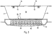
- FIG. 3 One possibility, not according to the invention, for realizing the virtual light sources is shown in Figure 3 shown.
- boards 16 with LEDs 15 are positioned at a distance from the optical element 10 with the lenses 20, the space between the LED boards 16 and the lens optics 10 now being bridged by a cavity 70 which forms a so-called mixing chamber.
- Light emitted by the LEDs 15, which in the case shown are oriented towards the lenses 20, but could also be arranged laterally in the mixing chamber 70, should therefore be reflected as often as possible in this mixing chamber 70 before it passes through the light entry areas 21 in the lens 20 enters and then is discharged to the bottom.
- the mixing chamber 70 is enclosed as completely as possible by reflective, in particular diffusely reflective, walls.
- the side walls 71 of the mixing chamber 70 are inclined, so that the mixing chamber 70 has a trapezoidal shape, in particular in cross section.
- the end faces and rear walls of the mixing chamber 70 are also preferably made of a diffusely reflective material or have a diffusely reflective coating, in which case the surfaces of the boards 16 themselves can also be designed to scatter light. All of these measures are intended to result in the light emitted by the LEDs 15 initially just as in the case of the light guide plate 30 according to FIG Figure 2 is mixed due to multiple reflections before it then enters the lenses 20 via the light entry surfaces 21.
- the occurrence of punctiform high luminous intensities is avoided.
- the light output is not only improved overall as a result, but any differences in the spectral composition of the light output by the LEDs can also be compensated for.
Landscapes
- Physics & Mathematics (AREA)
- General Physics & Mathematics (AREA)
- Optics & Photonics (AREA)
- Engineering & Computer Science (AREA)
- General Engineering & Computer Science (AREA)
- Planar Illumination Modules (AREA)
Claims (9)
- Ensemble d'émission de lumière, ayant :• un ensemble plat de lentilles (20), lesquelles présentent respectivement une zone d'entrée de lumière (21) ainsi qu'une zone de sortie de lumière (22),• des sources lumineuses sous forme de DEL (15), dont la lumière est émise à travers les lentilles (20), ainsi que• des moyens de distribution de lumière faisant face aux zones d'entrée de lumière (21) des lentilles (20), lesquels distribuent la lumière émise par les DEL (15) et la couplent dans la zone d'entrée de lumière (21) des lentilles (20),les moyens de distribution de lumière comprenant une plaque à guide d'ondes optiques (30), laquelle est formée pour distribuer de la lumière couplée dans la plaque à guide d'ondes optiques (30) et l'émettre à travers un côté plat (31) faisant face aux lentilles (20),
la plaque à guide d'ondes optiques (30) présentant dans la zone des zones d'entrée de lumière (21) des lentilles (20) des structures de découplage de lumière (33) sur sa surface (31), lesquelles devient les faisceaux de lumière incidents de telle façon que ceux-ci peuvent quitter la plaque à guide d'ondes optiques (30) et entrer dans les corps des lentilles (20),
les structures de découplage de lumière (33) correspondant, en ce qui concerne leurs dimensions, essentiellement aux dimensions des zones d'entrée de lumière (21) des lentilles (20), caractérisé en ce que les structures de découplage de lumière (33) sont réalisées en tant que rugosités ou de structures de dispersion. - Ensemble d'émission de lumière selon la revendication 1,
caractérisé en ce
que les DEL (15) sont disposées sur une ou plusieurs cartes de circuit imprimé (16), lesquelles sont disposées dans la zone de bord de la plaque à guide d'ondes optiques (30). - Ensemble d'émission de lumière selon la revendication 1 ou 2,
caractérisé en ce
que les DEL (15) sont disposées sur au moins une zone de bord de la plaque à guide d'ondes optiques (30), de préférence sur deux zones de bord opposées l'une à l'autre de la plaque à guide d'ondes optiques (30). - Ensemble selon l'une quelconque des revendications 1 à 3,
caractérisé en ce
que les structures de découplage de lumière (33) présentent une structure régulière, en particulier un structure réticulaire ou une structure rainurée. - Ensemble d'émission de lumière selon l'une quelconque des revendications précédentes,
caractérisé en ce
que celui-ci présente en outre une grille (25), dont les ouvertures correspondent, en ce qui concerne leur taille et positionnement, essentiellement aux zones d'entrée de lumière (21) des lentilles (20). - Ensemble d'émission de lumière selon l'une quelconque des revendications précédentes,
caractérisé en ce
que les lentilles (20) sont formées en forme de pyramide tronquée ou en forme de cône tronqué. - Ensemble d'émission de lumière selon l'une quelconque des revendications précédentes,
caractérisé en ce
que les lentilles (20) sont disposées en forme de matrice. - Ensemble d'émission de lumière selon la revendication 7,
caractérisé en ce
que les lentilles (20) sont groupées de façon intégrée en un élément optique (10). - Luminaire comprenant un ensemble d'émission de lumière selon l'une quelconque des revendications précédentes.
Applications Claiming Priority (3)
| Application Number | Priority Date | Filing Date | Title |
|---|---|---|---|
| DE102015219600 | 2015-10-09 | ||
| DE102016207137.8A DE102016207137A1 (de) | 2015-10-09 | 2016-04-27 | Anordnung zur Lichtabgabe |
| PCT/EP2016/074083 WO2017060479A1 (fr) | 2015-10-09 | 2016-10-07 | Dispositif d'émission de lumière |
Publications (2)
| Publication Number | Publication Date |
|---|---|
| EP3359874A1 EP3359874A1 (fr) | 2018-08-15 |
| EP3359874B1 true EP3359874B1 (fr) | 2020-12-09 |
Family
ID=58405897
Family Applications (1)
| Application Number | Title | Priority Date | Filing Date |
|---|---|---|---|
| EP16778064.2A Active EP3359874B1 (fr) | 2015-10-09 | 2016-10-07 | Dispositif d'émission de lumière |
Country Status (4)
| Country | Link |
|---|---|
| EP (1) | EP3359874B1 (fr) |
| AT (2) | AT16410U1 (fr) |
| DE (1) | DE102016207137A1 (fr) |
| WO (1) | WO2017060479A1 (fr) |
Citations (1)
| Publication number | Priority date | Publication date | Assignee | Title |
|---|---|---|---|---|
| DE102012215640A1 (de) * | 2012-09-04 | 2014-03-06 | Zumtobel Lighting Gmbh | Lichtleitereinheit für ein Beleuchtungssystem |
Family Cites Families (19)
| Publication number | Priority date | Publication date | Assignee | Title |
|---|---|---|---|---|
| DE10006410A1 (de) | 2000-02-14 | 2001-08-16 | Zumtobel Staff Gmbh | Leuchte |
| US5396350A (en) * | 1993-11-05 | 1995-03-07 | Alliedsignal Inc. | Backlighting apparatus employing an array of microprisms |
| US5428468A (en) * | 1993-11-05 | 1995-06-27 | Alliedsignal Inc. | Illumination system employing an array of microprisms |
| US6185357B1 (en) * | 1998-09-10 | 2001-02-06 | Honeywell International Inc. | Illumination system using edge-illuminated hollow waveguide and lenticular optical structures |
| EP1065436B1 (fr) * | 1999-05-28 | 2007-04-04 | Siteco Beleuchtungstechnik GmbH | Lampe de plafond avec guide de lumière |
| JP2004227835A (ja) * | 2003-01-21 | 2004-08-12 | Konica Minolta Holdings Inc | 照明装置および液晶表示装置 |
| US20050185416A1 (en) * | 2004-02-24 | 2005-08-25 | Eastman Kodak Company | Brightness enhancement film using light concentrator array |
| US7249869B2 (en) * | 2004-07-30 | 2007-07-31 | Toyoda Gosei Co., Ltd. | Light emitting device |
| US20080158476A1 (en) * | 2006-12-06 | 2008-07-03 | Citizen Electronics Co., Ltd. | Optical member, backlight unit and display apparatus having the same |
| DE102008014317A1 (de) * | 2008-03-14 | 2009-09-17 | Zumtobel Lighting Gmbh | Leuchte mit getrennten Leuchtmitteln für Direktbeleuchtung und Indirektbeleuchtung |
| EP2184628A3 (fr) * | 2008-11-06 | 2010-10-06 | CEAG Notlichtsysteme GmbH | Lampe, notamment lampe d'urgence, de sauvetage ou de sécurité |
| US8534896B2 (en) * | 2009-07-10 | 2013-09-17 | Koninklijke Philips N.V. | Free form lighting module |
| JP2013505549A (ja) * | 2009-09-21 | 2013-02-14 | コーニンクレッカ フィリップス エレクトロニクス エヌ ヴィ | ぎらつき低減を伴う反射型遮光部を備えた導光板を有する発光装置 |
| KR101441894B1 (ko) * | 2010-08-18 | 2014-09-19 | 주식회사 뷰라이팅인터내셔널 | 엘이디 확산렌즈 |
| KR20120044195A (ko) * | 2010-10-27 | 2012-05-07 | 엘지디스플레이 주식회사 | 액정표시장치 |
| WO2013046081A1 (fr) * | 2011-09-27 | 2013-04-04 | Koninklijke Philips Electronics N.V. | Système d'éclairage pour émettre un faisceau lumineux formé et luminaire |
| JP2013254649A (ja) * | 2012-06-07 | 2013-12-19 | Sharp Corp | 面光源装置、表示装置および照明装置 |
| WO2015082575A1 (fr) * | 2013-12-05 | 2015-06-11 | Koninklijke Philips N.V. | Dispositif optique, dispositif d'éclairage et système d'éclairage |
| DE102014200369A1 (de) * | 2014-01-10 | 2015-07-16 | Osram Gmbh | Flächenleuchtvorrichtung mit flächigem Lichtleiter |
-
2015
- 2015-12-22 AT ATGM386/2015U patent/AT16410U1/de not_active IP Right Cessation
-
2016
- 2016-04-27 DE DE102016207137.8A patent/DE102016207137A1/de not_active Withdrawn
- 2016-06-21 AT ATGM151/2016U patent/AT15384U1/de not_active IP Right Cessation
- 2016-10-07 EP EP16778064.2A patent/EP3359874B1/fr active Active
- 2016-10-07 WO PCT/EP2016/074083 patent/WO2017060479A1/fr not_active Ceased
Patent Citations (1)
| Publication number | Priority date | Publication date | Assignee | Title |
|---|---|---|---|---|
| DE102012215640A1 (de) * | 2012-09-04 | 2014-03-06 | Zumtobel Lighting Gmbh | Lichtleitereinheit für ein Beleuchtungssystem |
Also Published As
| Publication number | Publication date |
|---|---|
| DE102016207137A1 (de) | 2017-04-13 |
| WO2017060479A1 (fr) | 2017-04-13 |
| AT16410U1 (de) | 2019-08-15 |
| AT15384U1 (de) | 2017-07-15 |
| EP3359874A1 (fr) | 2018-08-15 |
Similar Documents
| Publication | Publication Date | Title |
|---|---|---|
| EP2281143B1 (fr) | Luminaire comportant des moyens d'éclairage distincts, pour éclairage direct et éclairage indirect | |
| EP2726779B1 (fr) | Ensemble émetteur de lumière à sources de lumière ponctuelles et élément de guidage de lumière | |
| AT16685U1 (de) | Direktstrahlende LED-Leuchte mit Entblendungsoptik | |
| DE102004002251A1 (de) | Leuchte mit verschiedenfarbigen Lichtquellen sowie einer Lichtleiterplatte zum Abgeben von Mischlicht | |
| DE102012111313B4 (de) | Beleuchtungseinheit für ein Kraftfahrzeug | |
| DE102004046256A1 (de) | Oberflächenleuchtsystem | |
| EP2587134A1 (fr) | Eclairage | |
| EP3092439A2 (fr) | Dispositif d'éclairage | |
| EP2982903B1 (fr) | Système d'éclairage et dispositif d'éclairage equipé dudit système | |
| EP3359874B1 (fr) | Dispositif d'émission de lumière | |
| EP2642470B1 (fr) | Elément d'éclairage en forme de plaque et lampe dotée d'un élément d'éclairage | |
| EP3408587B1 (fr) | Système optique destiné à influer sur l'émission de lumière d'une source de lumière | |
| EP3869093B1 (fr) | Luminaire à lumière à émission lumineuse directe et indirecte | |
| EP2924343B1 (fr) | Lampe à del dotée d'une optique réfractive destinée au mélange de la lumière | |
| EP3591281B1 (fr) | Luminaire de l'habitacle | |
| EP4168711B1 (fr) | Ensemble d'émission de lumière, et luminaire | |
| DE202005001507U1 (de) | Oberflächenleuchtsystem | |
| EP3329178B1 (fr) | Élément guide de lumière | |
| EP3358250B1 (fr) | Luminaire pourvu d'une plaque de guidage de lumière avec des structures de déviation | |
| DE202024104176U1 (de) | Modulares System zum Bilden einer Leuchte | |
| EP2487409A1 (fr) | Réflecteur pour moyens d'éclairage | |
| EP3270048A1 (fr) | Éclairage comprenant des ouvertures de passage | |
| DE102013224597A1 (de) | Optischer Strahler |
Legal Events
| Date | Code | Title | Description |
|---|---|---|---|
| STAA | Information on the status of an ep patent application or granted ep patent |
Free format text: STATUS: THE INTERNATIONAL PUBLICATION HAS BEEN MADE |
|
| PUAI | Public reference made under article 153(3) epc to a published international application that has entered the european phase |
Free format text: ORIGINAL CODE: 0009012 |
|
| STAA | Information on the status of an ep patent application or granted ep patent |
Free format text: STATUS: REQUEST FOR EXAMINATION WAS MADE |
|
| 17P | Request for examination filed |
Effective date: 20180327 |
|
| AK | Designated contracting states |
Kind code of ref document: A1 Designated state(s): AL AT BE BG CH CY CZ DE DK EE ES FI FR GB GR HR HU IE IS IT LI LT LU LV MC MK MT NL NO PL PT RO RS SE SI SK SM TR |
|
| AX | Request for extension of the european patent |
Extension state: BA ME |
|
| RIN1 | Information on inventor provided before grant (corrected) |
Inventor name: NIEDERSTAETTER, ANDREAS Inventor name: CERV, SIMON Inventor name: FRICK, JOACHIM Inventor name: REIN, THOMAS Inventor name: SCHWAIGHOFER, ANDREAS |
|
| RIN1 | Information on inventor provided before grant (corrected) |
Inventor name: NIEDERSTAETTER, ANDREAS Inventor name: SCHWAIGHOFER, ANDREAS Inventor name: FRICK, JOACHIM Inventor name: CERV, SIMON Inventor name: REIN, THOMAS |
|
| DAV | Request for validation of the european patent (deleted) | ||
| DAX | Request for extension of the european patent (deleted) | ||
| STAA | Information on the status of an ep patent application or granted ep patent |
Free format text: STATUS: EXAMINATION IS IN PROGRESS |
|
| 17Q | First examination report despatched |
Effective date: 20191126 |
|
| GRAP | Despatch of communication of intention to grant a patent |
Free format text: ORIGINAL CODE: EPIDOSNIGR1 |
|
| STAA | Information on the status of an ep patent application or granted ep patent |
Free format text: STATUS: GRANT OF PATENT IS INTENDED |
|
| INTG | Intention to grant announced |
Effective date: 20200828 |
|
| GRAS | Grant fee paid |
Free format text: ORIGINAL CODE: EPIDOSNIGR3 |
|
| GRAA | (expected) grant |
Free format text: ORIGINAL CODE: 0009210 |
|
| STAA | Information on the status of an ep patent application or granted ep patent |
Free format text: STATUS: THE PATENT HAS BEEN GRANTED |
|
| AK | Designated contracting states |
Kind code of ref document: B1 Designated state(s): AL AT BE BG CH CY CZ DE DK EE ES FI FR GB GR HR HU IE IS IT LI LT LU LV MC MK MT NL NO PL PT RO RS SE SI SK SM TR |
|
| REG | Reference to a national code |
Ref country code: GB Ref legal event code: FG4D Free format text: NOT ENGLISH |
|
| REG | Reference to a national code |
Ref country code: AT Ref legal event code: REF Ref document number: 1343826 Country of ref document: AT Kind code of ref document: T Effective date: 20201215 Ref country code: CH Ref legal event code: EP |
|
| REG | Reference to a national code |
Ref country code: DE Ref legal event code: R096 Ref document number: 502016011942 Country of ref document: DE |
|
| REG | Reference to a national code |
Ref country code: IE Ref legal event code: FG4D Free format text: LANGUAGE OF EP DOCUMENT: GERMAN |
|
| PG25 | Lapsed in a contracting state [announced via postgrant information from national office to epo] |
Ref country code: FI Free format text: LAPSE BECAUSE OF FAILURE TO SUBMIT A TRANSLATION OF THE DESCRIPTION OR TO PAY THE FEE WITHIN THE PRESCRIBED TIME-LIMIT Effective date: 20201209 Ref country code: GR Free format text: LAPSE BECAUSE OF FAILURE TO SUBMIT A TRANSLATION OF THE DESCRIPTION OR TO PAY THE FEE WITHIN THE PRESCRIBED TIME-LIMIT Effective date: 20210310 Ref country code: RS Free format text: LAPSE BECAUSE OF FAILURE TO SUBMIT A TRANSLATION OF THE DESCRIPTION OR TO PAY THE FEE WITHIN THE PRESCRIBED TIME-LIMIT Effective date: 20201209 Ref country code: NO Free format text: LAPSE BECAUSE OF FAILURE TO SUBMIT A TRANSLATION OF THE DESCRIPTION OR TO PAY THE FEE WITHIN THE PRESCRIBED TIME-LIMIT Effective date: 20210309 |
|
| PG25 | Lapsed in a contracting state [announced via postgrant information from national office to epo] |
Ref country code: SE Free format text: LAPSE BECAUSE OF FAILURE TO SUBMIT A TRANSLATION OF THE DESCRIPTION OR TO PAY THE FEE WITHIN THE PRESCRIBED TIME-LIMIT Effective date: 20201209 Ref country code: BG Free format text: LAPSE BECAUSE OF FAILURE TO SUBMIT A TRANSLATION OF THE DESCRIPTION OR TO PAY THE FEE WITHIN THE PRESCRIBED TIME-LIMIT Effective date: 20210309 Ref country code: LV Free format text: LAPSE BECAUSE OF FAILURE TO SUBMIT A TRANSLATION OF THE DESCRIPTION OR TO PAY THE FEE WITHIN THE PRESCRIBED TIME-LIMIT Effective date: 20201209 |
|
| REG | Reference to a national code |
Ref country code: NL Ref legal event code: MP Effective date: 20201209 |
|
| PG25 | Lapsed in a contracting state [announced via postgrant information from national office to epo] |
Ref country code: NL Free format text: LAPSE BECAUSE OF FAILURE TO SUBMIT A TRANSLATION OF THE DESCRIPTION OR TO PAY THE FEE WITHIN THE PRESCRIBED TIME-LIMIT Effective date: 20201209 Ref country code: HR Free format text: LAPSE BECAUSE OF FAILURE TO SUBMIT A TRANSLATION OF THE DESCRIPTION OR TO PAY THE FEE WITHIN THE PRESCRIBED TIME-LIMIT Effective date: 20201209 |
|
| REG | Reference to a national code |
Ref country code: LT Ref legal event code: MG9D |
|
| PG25 | Lapsed in a contracting state [announced via postgrant information from national office to epo] |
Ref country code: PT Free format text: LAPSE BECAUSE OF FAILURE TO SUBMIT A TRANSLATION OF THE DESCRIPTION OR TO PAY THE FEE WITHIN THE PRESCRIBED TIME-LIMIT Effective date: 20210409 Ref country code: RO Free format text: LAPSE BECAUSE OF FAILURE TO SUBMIT A TRANSLATION OF THE DESCRIPTION OR TO PAY THE FEE WITHIN THE PRESCRIBED TIME-LIMIT Effective date: 20201209 Ref country code: SK Free format text: LAPSE BECAUSE OF FAILURE TO SUBMIT A TRANSLATION OF THE DESCRIPTION OR TO PAY THE FEE WITHIN THE PRESCRIBED TIME-LIMIT Effective date: 20201209 Ref country code: SM Free format text: LAPSE BECAUSE OF FAILURE TO SUBMIT A TRANSLATION OF THE DESCRIPTION OR TO PAY THE FEE WITHIN THE PRESCRIBED TIME-LIMIT Effective date: 20201209 Ref country code: LT Free format text: LAPSE BECAUSE OF FAILURE TO SUBMIT A TRANSLATION OF THE DESCRIPTION OR TO PAY THE FEE WITHIN THE PRESCRIBED TIME-LIMIT Effective date: 20201209 Ref country code: CZ Free format text: LAPSE BECAUSE OF FAILURE TO SUBMIT A TRANSLATION OF THE DESCRIPTION OR TO PAY THE FEE WITHIN THE PRESCRIBED TIME-LIMIT Effective date: 20201209 Ref country code: EE Free format text: LAPSE BECAUSE OF FAILURE TO SUBMIT A TRANSLATION OF THE DESCRIPTION OR TO PAY THE FEE WITHIN THE PRESCRIBED TIME-LIMIT Effective date: 20201209 |
|
| PG25 | Lapsed in a contracting state [announced via postgrant information from national office to epo] |
Ref country code: PL Free format text: LAPSE BECAUSE OF FAILURE TO SUBMIT A TRANSLATION OF THE DESCRIPTION OR TO PAY THE FEE WITHIN THE PRESCRIBED TIME-LIMIT Effective date: 20201209 |
|
| REG | Reference to a national code |
Ref country code: DE Ref legal event code: R097 Ref document number: 502016011942 Country of ref document: DE |
|
| PG25 | Lapsed in a contracting state [announced via postgrant information from national office to epo] |
Ref country code: IS Free format text: LAPSE BECAUSE OF FAILURE TO SUBMIT A TRANSLATION OF THE DESCRIPTION OR TO PAY THE FEE WITHIN THE PRESCRIBED TIME-LIMIT Effective date: 20210409 |
|
| PLBE | No opposition filed within time limit |
Free format text: ORIGINAL CODE: 0009261 |
|
| STAA | Information on the status of an ep patent application or granted ep patent |
Free format text: STATUS: NO OPPOSITION FILED WITHIN TIME LIMIT |
|
| PG25 | Lapsed in a contracting state [announced via postgrant information from national office to epo] |
Ref country code: AL Free format text: LAPSE BECAUSE OF FAILURE TO SUBMIT A TRANSLATION OF THE DESCRIPTION OR TO PAY THE FEE WITHIN THE PRESCRIBED TIME-LIMIT Effective date: 20201209 Ref country code: IT Free format text: LAPSE BECAUSE OF FAILURE TO SUBMIT A TRANSLATION OF THE DESCRIPTION OR TO PAY THE FEE WITHIN THE PRESCRIBED TIME-LIMIT Effective date: 20201209 |
|
| 26N | No opposition filed |
Effective date: 20210910 |
|
| PG25 | Lapsed in a contracting state [announced via postgrant information from national office to epo] |
Ref country code: DK Free format text: LAPSE BECAUSE OF FAILURE TO SUBMIT A TRANSLATION OF THE DESCRIPTION OR TO PAY THE FEE WITHIN THE PRESCRIBED TIME-LIMIT Effective date: 20201209 Ref country code: SI Free format text: LAPSE BECAUSE OF FAILURE TO SUBMIT A TRANSLATION OF THE DESCRIPTION OR TO PAY THE FEE WITHIN THE PRESCRIBED TIME-LIMIT Effective date: 20201209 |
|
| PG25 | Lapsed in a contracting state [announced via postgrant information from national office to epo] |
Ref country code: ES Free format text: LAPSE BECAUSE OF FAILURE TO SUBMIT A TRANSLATION OF THE DESCRIPTION OR TO PAY THE FEE WITHIN THE PRESCRIBED TIME-LIMIT Effective date: 20201209 |
|
| REG | Reference to a national code |
Ref country code: CH Ref legal event code: PL |
|
| PG25 | Lapsed in a contracting state [announced via postgrant information from national office to epo] |
Ref country code: IS Free format text: LAPSE BECAUSE OF FAILURE TO SUBMIT A TRANSLATION OF THE DESCRIPTION OR TO PAY THE FEE WITHIN THE PRESCRIBED TIME-LIMIT Effective date: 20210409 |
|
| REG | Reference to a national code |
Ref country code: BE Ref legal event code: MM Effective date: 20211031 |
|
| PG25 | Lapsed in a contracting state [announced via postgrant information from national office to epo] |
Ref country code: MC Free format text: LAPSE BECAUSE OF FAILURE TO SUBMIT A TRANSLATION OF THE DESCRIPTION OR TO PAY THE FEE WITHIN THE PRESCRIBED TIME-LIMIT Effective date: 20201209 |
|
| PG25 | Lapsed in a contracting state [announced via postgrant information from national office to epo] |
Ref country code: LU Free format text: LAPSE BECAUSE OF NON-PAYMENT OF DUE FEES Effective date: 20211007 Ref country code: BE Free format text: LAPSE BECAUSE OF NON-PAYMENT OF DUE FEES Effective date: 20211031 |
|
| PG25 | Lapsed in a contracting state [announced via postgrant information from national office to epo] |
Ref country code: LI Free format text: LAPSE BECAUSE OF NON-PAYMENT OF DUE FEES Effective date: 20211031 Ref country code: CH Free format text: LAPSE BECAUSE OF NON-PAYMENT OF DUE FEES Effective date: 20211031 |
|
| PG25 | Lapsed in a contracting state [announced via postgrant information from national office to epo] |
Ref country code: IE Free format text: LAPSE BECAUSE OF NON-PAYMENT OF DUE FEES Effective date: 20211007 |
|
| REG | Reference to a national code |
Ref country code: AT Ref legal event code: MM01 Ref document number: 1343826 Country of ref document: AT Kind code of ref document: T Effective date: 20211007 |
|
| PGFP | Annual fee paid to national office [announced via postgrant information from national office to epo] |
Ref country code: FR Payment date: 20221024 Year of fee payment: 7 |
|
| PG25 | Lapsed in a contracting state [announced via postgrant information from national office to epo] |
Ref country code: AT Free format text: LAPSE BECAUSE OF NON-PAYMENT OF DUE FEES Effective date: 20211007 |
|
| PG25 | Lapsed in a contracting state [announced via postgrant information from national office to epo] |
Ref country code: HU Free format text: LAPSE BECAUSE OF FAILURE TO SUBMIT A TRANSLATION OF THE DESCRIPTION OR TO PAY THE FEE WITHIN THE PRESCRIBED TIME-LIMIT; INVALID AB INITIO Effective date: 20161007 |
|
| PG25 | Lapsed in a contracting state [announced via postgrant information from national office to epo] |
Ref country code: CY Free format text: LAPSE BECAUSE OF FAILURE TO SUBMIT A TRANSLATION OF THE DESCRIPTION OR TO PAY THE FEE WITHIN THE PRESCRIBED TIME-LIMIT Effective date: 20201209 |
|
| P01 | Opt-out of the competence of the unified patent court (upc) registered |
Effective date: 20230530 |
|
| REG | Reference to a national code |
Ref country code: DE Ref legal event code: R084 Ref document number: 502016011942 Country of ref document: DE |
|
| PG25 | Lapsed in a contracting state [announced via postgrant information from national office to epo] |
Ref country code: MK Free format text: LAPSE BECAUSE OF FAILURE TO SUBMIT A TRANSLATION OF THE DESCRIPTION OR TO PAY THE FEE WITHIN THE PRESCRIBED TIME-LIMIT Effective date: 20201209 |
|
| PG25 | Lapsed in a contracting state [announced via postgrant information from national office to epo] |
Ref country code: TR Free format text: LAPSE BECAUSE OF FAILURE TO SUBMIT A TRANSLATION OF THE DESCRIPTION OR TO PAY THE FEE WITHIN THE PRESCRIBED TIME-LIMIT Effective date: 20201209 |
|
| PG25 | Lapsed in a contracting state [announced via postgrant information from national office to epo] |
Ref country code: FR Free format text: LAPSE BECAUSE OF NON-PAYMENT OF DUE FEES Effective date: 20231031 |
|
| PG25 | Lapsed in a contracting state [announced via postgrant information from national office to epo] |
Ref country code: MT Free format text: LAPSE BECAUSE OF FAILURE TO SUBMIT A TRANSLATION OF THE DESCRIPTION OR TO PAY THE FEE WITHIN THE PRESCRIBED TIME-LIMIT Effective date: 20201209 |
|
| PGFP | Annual fee paid to national office [announced via postgrant information from national office to epo] |
Ref country code: GB Payment date: 20241023 Year of fee payment: 9 |
|
| PGFP | Annual fee paid to national office [announced via postgrant information from national office to epo] |
Ref country code: DE Payment date: 20251028 Year of fee payment: 10 |