EP3360496B1 - Raccordement de fluide et cryosonde le comprenant - Google Patents
Raccordement de fluide et cryosonde le comprenant Download PDFInfo
- Publication number
- EP3360496B1 EP3360496B1 EP17155740.8A EP17155740A EP3360496B1 EP 3360496 B1 EP3360496 B1 EP 3360496B1 EP 17155740 A EP17155740 A EP 17155740A EP 3360496 B1 EP3360496 B1 EP 3360496B1
- Authority
- EP
- European Patent Office
- Prior art keywords
- line
- adhesive
- socket
- fluid
- inner line
- Prior art date
- Legal status (The legal status is an assumption and is not a legal conclusion. Google has not performed a legal analysis and makes no representation as to the accuracy of the status listed.)
- Active
Links
Images



Classifications
-
- A—HUMAN NECESSITIES
- A61—MEDICAL OR VETERINARY SCIENCE; HYGIENE
- A61B—DIAGNOSIS; SURGERY; IDENTIFICATION
- A61B18/00—Surgical instruments, devices or methods for transferring non-mechanical forms of energy to or from the body
-
- A—HUMAN NECESSITIES
- A61—MEDICAL OR VETERINARY SCIENCE; HYGIENE
- A61B—DIAGNOSIS; SURGERY; IDENTIFICATION
- A61B18/00—Surgical instruments, devices or methods for transferring non-mechanical forms of energy to or from the body
- A61B18/02—Surgical instruments, devices or methods for transferring non-mechanical forms of energy to or from the body by cooling, e.g. cryogenic techniques
-
- A—HUMAN NECESSITIES
- A61—MEDICAL OR VETERINARY SCIENCE; HYGIENE
- A61B—DIAGNOSIS; SURGERY; IDENTIFICATION
- A61B17/00—Surgical instruments, devices or methods
-
- A—HUMAN NECESSITIES
- A61—MEDICAL OR VETERINARY SCIENCE; HYGIENE
- A61B—DIAGNOSIS; SURGERY; IDENTIFICATION
- A61B17/00—Surgical instruments, devices or methods
- A61B17/00491—Surgical glue applicators
-
- B—PERFORMING OPERATIONS; TRANSPORTING
- B29—WORKING OF PLASTICS; WORKING OF SUBSTANCES IN A PLASTIC STATE IN GENERAL
- B29C—SHAPING OR JOINING OF PLASTICS; SHAPING OF MATERIAL IN A PLASTIC STATE, NOT OTHERWISE PROVIDED FOR; AFTER-TREATMENT OF THE SHAPED PRODUCTS, e.g. REPAIRING
- B29C65/00—Joining or sealing of preformed parts, e.g. welding of plastics materials; Apparatus therefor
- B29C65/02—Joining or sealing of preformed parts, e.g. welding of plastics materials; Apparatus therefor by heating, with or without pressure
- B29C65/14—Joining or sealing of preformed parts, e.g. welding of plastics materials; Apparatus therefor by heating, with or without pressure using wave energy, i.e. electromagnetic radiation, or particle radiation
- B29C65/1403—Joining or sealing of preformed parts, e.g. welding of plastics materials; Apparatus therefor by heating, with or without pressure using wave energy, i.e. electromagnetic radiation, or particle radiation characterised by the type of electromagnetic or particle radiation
- B29C65/1406—Ultraviolet [UV] radiation
-
- B—PERFORMING OPERATIONS; TRANSPORTING
- B29—WORKING OF PLASTICS; WORKING OF SUBSTANCES IN A PLASTIC STATE IN GENERAL
- B29C—SHAPING OR JOINING OF PLASTICS; SHAPING OF MATERIAL IN A PLASTIC STATE, NOT OTHERWISE PROVIDED FOR; AFTER-TREATMENT OF THE SHAPED PRODUCTS, e.g. REPAIRING
- B29C65/00—Joining or sealing of preformed parts, e.g. welding of plastics materials; Apparatus therefor
- B29C65/02—Joining or sealing of preformed parts, e.g. welding of plastics materials; Apparatus therefor by heating, with or without pressure
- B29C65/14—Joining or sealing of preformed parts, e.g. welding of plastics materials; Apparatus therefor by heating, with or without pressure using wave energy, i.e. electromagnetic radiation, or particle radiation
- B29C65/1429—Joining or sealing of preformed parts, e.g. welding of plastics materials; Apparatus therefor by heating, with or without pressure using wave energy, i.e. electromagnetic radiation, or particle radiation characterised by the way of heating the interface
- B29C65/1435—Joining or sealing of preformed parts, e.g. welding of plastics materials; Apparatus therefor by heating, with or without pressure using wave energy, i.e. electromagnetic radiation, or particle radiation characterised by the way of heating the interface at least passing through one of the parts to be joined, i.e. transmission welding
-
- B—PERFORMING OPERATIONS; TRANSPORTING
- B29—WORKING OF PLASTICS; WORKING OF SUBSTANCES IN A PLASTIC STATE IN GENERAL
- B29C—SHAPING OR JOINING OF PLASTICS; SHAPING OF MATERIAL IN A PLASTIC STATE, NOT OTHERWISE PROVIDED FOR; AFTER-TREATMENT OF THE SHAPED PRODUCTS, e.g. REPAIRING
- B29C65/00—Joining or sealing of preformed parts, e.g. welding of plastics materials; Apparatus therefor
- B29C65/48—Joining or sealing of preformed parts, e.g. welding of plastics materials; Apparatus therefor using adhesives, i.e. using supplementary joining material; solvent bonding
- B29C65/4805—Joining or sealing of preformed parts, e.g. welding of plastics materials; Apparatus therefor using adhesives, i.e. using supplementary joining material; solvent bonding characterised by the type of adhesives
- B29C65/483—Reactive adhesives, e.g. chemically curing adhesives
- B29C65/4845—Radiation curing adhesives, e.g. UV light curing adhesives
-
- B—PERFORMING OPERATIONS; TRANSPORTING
- B29—WORKING OF PLASTICS; WORKING OF SUBSTANCES IN A PLASTIC STATE IN GENERAL
- B29C—SHAPING OR JOINING OF PLASTICS; SHAPING OF MATERIAL IN A PLASTIC STATE, NOT OTHERWISE PROVIDED FOR; AFTER-TREATMENT OF THE SHAPED PRODUCTS, e.g. REPAIRING
- B29C65/00—Joining or sealing of preformed parts, e.g. welding of plastics materials; Apparatus therefor
- B29C65/48—Joining or sealing of preformed parts, e.g. welding of plastics materials; Apparatus therefor using adhesives, i.e. using supplementary joining material; solvent bonding
- B29C65/52—Joining or sealing of preformed parts, e.g. welding of plastics materials; Apparatus therefor using adhesives, i.e. using supplementary joining material; solvent bonding characterised by the way of applying the adhesive
- B29C65/54—Joining or sealing of preformed parts, e.g. welding of plastics materials; Apparatus therefor using adhesives, i.e. using supplementary joining material; solvent bonding characterised by the way of applying the adhesive between pre-assembled parts
- B29C65/548—Joining or sealing of preformed parts, e.g. welding of plastics materials; Apparatus therefor using adhesives, i.e. using supplementary joining material; solvent bonding characterised by the way of applying the adhesive between pre-assembled parts by capillarity
-
- B—PERFORMING OPERATIONS; TRANSPORTING
- B29—WORKING OF PLASTICS; WORKING OF SUBSTANCES IN A PLASTIC STATE IN GENERAL
- B29C—SHAPING OR JOINING OF PLASTICS; SHAPING OF MATERIAL IN A PLASTIC STATE, NOT OTHERWISE PROVIDED FOR; AFTER-TREATMENT OF THE SHAPED PRODUCTS, e.g. REPAIRING
- B29C66/00—General aspects of processes or apparatus for joining preformed parts
- B29C66/01—General aspects dealing with the joint area or with the area to be joined
- B29C66/05—Particular design of joint configurations
- B29C66/10—Particular design of joint configurations particular design of the joint cross-sections
- B29C66/12—Joint cross-sections combining only two joint-segments; Tongue and groove joints; Tenon and mortise joints; Stepped joint cross-sections
- B29C66/122—Joint cross-sections combining only two joint-segments, i.e. one of the parts to be joined comprising only two joint-segments in the joint cross-section
- B29C66/1222—Joint cross-sections combining only two joint-segments, i.e. one of the parts to be joined comprising only two joint-segments in the joint cross-section comprising at least a lapped joint-segment
-
- B—PERFORMING OPERATIONS; TRANSPORTING
- B29—WORKING OF PLASTICS; WORKING OF SUBSTANCES IN A PLASTIC STATE IN GENERAL
- B29C—SHAPING OR JOINING OF PLASTICS; SHAPING OF MATERIAL IN A PLASTIC STATE, NOT OTHERWISE PROVIDED FOR; AFTER-TREATMENT OF THE SHAPED PRODUCTS, e.g. REPAIRING
- B29C66/00—General aspects of processes or apparatus for joining preformed parts
- B29C66/01—General aspects dealing with the joint area or with the area to be joined
- B29C66/05—Particular design of joint configurations
- B29C66/10—Particular design of joint configurations particular design of the joint cross-sections
- B29C66/12—Joint cross-sections combining only two joint-segments; Tongue and groove joints; Tenon and mortise joints; Stepped joint cross-sections
- B29C66/122—Joint cross-sections combining only two joint-segments, i.e. one of the parts to be joined comprising only two joint-segments in the joint cross-section
- B29C66/1224—Joint cross-sections combining only two joint-segments, i.e. one of the parts to be joined comprising only two joint-segments in the joint cross-section comprising at least a butt joint-segment
-
- B—PERFORMING OPERATIONS; TRANSPORTING
- B29—WORKING OF PLASTICS; WORKING OF SUBSTANCES IN A PLASTIC STATE IN GENERAL
- B29C—SHAPING OR JOINING OF PLASTICS; SHAPING OF MATERIAL IN A PLASTIC STATE, NOT OTHERWISE PROVIDED FOR; AFTER-TREATMENT OF THE SHAPED PRODUCTS, e.g. REPAIRING
- B29C66/00—General aspects of processes or apparatus for joining preformed parts
- B29C66/01—General aspects dealing with the joint area or with the area to be joined
- B29C66/32—Measures for keeping the burr form under control; Avoiding burr formation; Shaping the burr
- B29C66/322—Providing cavities in the joined article to collect the burr
-
- B—PERFORMING OPERATIONS; TRANSPORTING
- B29—WORKING OF PLASTICS; WORKING OF SUBSTANCES IN A PLASTIC STATE IN GENERAL
- B29C—SHAPING OR JOINING OF PLASTICS; SHAPING OF MATERIAL IN A PLASTIC STATE, NOT OTHERWISE PROVIDED FOR; AFTER-TREATMENT OF THE SHAPED PRODUCTS, e.g. REPAIRING
- B29C66/00—General aspects of processes or apparatus for joining preformed parts
- B29C66/50—General aspects of joining tubular articles; General aspects of joining long products, i.e. bars or profiled elements; General aspects of joining single elements to tubular articles, hollow articles or bars; General aspects of joining several hollow-preforms to form hollow or tubular articles
- B29C66/51—Joining tubular articles, profiled elements or bars; Joining single elements to tubular articles, hollow articles or bars; Joining several hollow-preforms to form hollow or tubular articles
- B29C66/52—Joining tubular articles, bars or profiled elements
- B29C66/522—Joining tubular articles
- B29C66/5221—Joining tubular articles for forming coaxial connections, i.e. the tubular articles to be joined forming a zero angle relative to each other
-
- B—PERFORMING OPERATIONS; TRANSPORTING
- B29—WORKING OF PLASTICS; WORKING OF SUBSTANCES IN A PLASTIC STATE IN GENERAL
- B29C—SHAPING OR JOINING OF PLASTICS; SHAPING OF MATERIAL IN A PLASTIC STATE, NOT OTHERWISE PROVIDED FOR; AFTER-TREATMENT OF THE SHAPED PRODUCTS, e.g. REPAIRING
- B29C66/00—General aspects of processes or apparatus for joining preformed parts
- B29C66/50—General aspects of joining tubular articles; General aspects of joining long products, i.e. bars or profiled elements; General aspects of joining single elements to tubular articles, hollow articles or bars; General aspects of joining several hollow-preforms to form hollow or tubular articles
- B29C66/51—Joining tubular articles, profiled elements or bars; Joining single elements to tubular articles, hollow articles or bars; Joining several hollow-preforms to form hollow or tubular articles
- B29C66/52—Joining tubular articles, bars or profiled elements
- B29C66/522—Joining tubular articles
- B29C66/5229—Joining tubular articles involving the use of a socket
- B29C66/52291—Joining tubular articles involving the use of a socket said socket comprising a stop
- B29C66/52292—Joining tubular articles involving the use of a socket said socket comprising a stop said stop being internal
-
- B—PERFORMING OPERATIONS; TRANSPORTING
- B29—WORKING OF PLASTICS; WORKING OF SUBSTANCES IN A PLASTIC STATE IN GENERAL
- B29C—SHAPING OR JOINING OF PLASTICS; SHAPING OF MATERIAL IN A PLASTIC STATE, NOT OTHERWISE PROVIDED FOR; AFTER-TREATMENT OF THE SHAPED PRODUCTS, e.g. REPAIRING
- B29C66/00—General aspects of processes or apparatus for joining preformed parts
- B29C66/50—General aspects of joining tubular articles; General aspects of joining long products, i.e. bars or profiled elements; General aspects of joining single elements to tubular articles, hollow articles or bars; General aspects of joining several hollow-preforms to form hollow or tubular articles
- B29C66/51—Joining tubular articles, profiled elements or bars; Joining single elements to tubular articles, hollow articles or bars; Joining several hollow-preforms to form hollow or tubular articles
- B29C66/52—Joining tubular articles, bars or profiled elements
- B29C66/522—Joining tubular articles
- B29C66/5229—Joining tubular articles involving the use of a socket
- B29C66/52291—Joining tubular articles involving the use of a socket said socket comprising a stop
- B29C66/52293—Joining tubular articles involving the use of a socket said socket comprising a stop said stop being external
-
- B—PERFORMING OPERATIONS; TRANSPORTING
- B29—WORKING OF PLASTICS; WORKING OF SUBSTANCES IN A PLASTIC STATE IN GENERAL
- B29C—SHAPING OR JOINING OF PLASTICS; SHAPING OF MATERIAL IN A PLASTIC STATE, NOT OTHERWISE PROVIDED FOR; AFTER-TREATMENT OF THE SHAPED PRODUCTS, e.g. REPAIRING
- B29C66/00—General aspects of processes or apparatus for joining preformed parts
- B29C66/50—General aspects of joining tubular articles; General aspects of joining long products, i.e. bars or profiled elements; General aspects of joining single elements to tubular articles, hollow articles or bars; General aspects of joining several hollow-preforms to form hollow or tubular articles
- B29C66/51—Joining tubular articles, profiled elements or bars; Joining single elements to tubular articles, hollow articles or bars; Joining several hollow-preforms to form hollow or tubular articles
- B29C66/53—Joining single elements to tubular articles, hollow articles or bars
- B29C66/534—Joining single elements to open ends of tubular or hollow articles or to the ends of bars
- B29C66/5344—Joining single elements to open ends of tubular or hollow articles or to the ends of bars said single elements being substantially annular, i.e. of finite length, e.g. joining flanges to tube ends
-
- A—HUMAN NECESSITIES
- A61—MEDICAL OR VETERINARY SCIENCE; HYGIENE
- A61B—DIAGNOSIS; SURGERY; IDENTIFICATION
- A61B17/00—Surgical instruments, devices or methods
- A61B2017/00017—Electrical control of surgical instruments
-
- A—HUMAN NECESSITIES
- A61—MEDICAL OR VETERINARY SCIENCE; HYGIENE
- A61B—DIAGNOSIS; SURGERY; IDENTIFICATION
- A61B17/00—Surgical instruments, devices or methods
- A61B2017/00831—Material properties
-
- A—HUMAN NECESSITIES
- A61—MEDICAL OR VETERINARY SCIENCE; HYGIENE
- A61B—DIAGNOSIS; SURGERY; IDENTIFICATION
- A61B18/00—Surgical instruments, devices or methods for transferring non-mechanical forms of energy to or from the body
- A61B2018/00005—Cooling or heating of the probe or tissue immediately surrounding the probe
-
- A—HUMAN NECESSITIES
- A61—MEDICAL OR VETERINARY SCIENCE; HYGIENE
- A61B—DIAGNOSIS; SURGERY; IDENTIFICATION
- A61B18/00—Surgical instruments, devices or methods for transferring non-mechanical forms of energy to or from the body
- A61B2018/00005—Cooling or heating of the probe or tissue immediately surrounding the probe
- A61B2018/00011—Cooling or heating of the probe or tissue immediately surrounding the probe with fluids
-
- A—HUMAN NECESSITIES
- A61—MEDICAL OR VETERINARY SCIENCE; HYGIENE
- A61B—DIAGNOSIS; SURGERY; IDENTIFICATION
- A61B18/00—Surgical instruments, devices or methods for transferring non-mechanical forms of energy to or from the body
- A61B2018/00053—Mechanical features of the instrument of device
- A61B2018/00172—Connectors and adapters therefor
-
- A—HUMAN NECESSITIES
- A61—MEDICAL OR VETERINARY SCIENCE; HYGIENE
- A61B—DIAGNOSIS; SURGERY; IDENTIFICATION
- A61B18/00—Surgical instruments, devices or methods for transferring non-mechanical forms of energy to or from the body
- A61B2018/00982—Surgical instruments, devices or methods for transferring non-mechanical forms of energy to or from the body combined with or comprising means for visual or photographic inspections inside the body, e.g. endoscopes
-
- A—HUMAN NECESSITIES
- A61—MEDICAL OR VETERINARY SCIENCE; HYGIENE
- A61B—DIAGNOSIS; SURGERY; IDENTIFICATION
- A61B18/00—Surgical instruments, devices or methods for transferring non-mechanical forms of energy to or from the body
- A61B18/02—Surgical instruments, devices or methods for transferring non-mechanical forms of energy to or from the body by cooling, e.g. cryogenic techniques
- A61B2018/0212—Surgical instruments, devices or methods for transferring non-mechanical forms of energy to or from the body by cooling, e.g. cryogenic techniques using an instrument inserted into a body lumen, e.g. catheter
-
- A—HUMAN NECESSITIES
- A61—MEDICAL OR VETERINARY SCIENCE; HYGIENE
- A61B—DIAGNOSIS; SURGERY; IDENTIFICATION
- A61B18/00—Surgical instruments, devices or methods for transferring non-mechanical forms of energy to or from the body
- A61B18/02—Surgical instruments, devices or methods for transferring non-mechanical forms of energy to or from the body by cooling, e.g. cryogenic techniques
- A61B2018/0231—Characteristics of handpieces or probes
-
- A—HUMAN NECESSITIES
- A61—MEDICAL OR VETERINARY SCIENCE; HYGIENE
- A61B—DIAGNOSIS; SURGERY; IDENTIFICATION
- A61B18/00—Surgical instruments, devices or methods for transferring non-mechanical forms of energy to or from the body
- A61B18/02—Surgical instruments, devices or methods for transferring non-mechanical forms of energy to or from the body by cooling, e.g. cryogenic techniques
- A61B2018/0231—Characteristics of handpieces or probes
- A61B2018/0262—Characteristics of handpieces or probes using a circulating cryogenic fluid
-
- A—HUMAN NECESSITIES
- A61—MEDICAL OR VETERINARY SCIENCE; HYGIENE
- A61M—DEVICES FOR INTRODUCING MEDIA INTO, OR ONTO, THE BODY; DEVICES FOR TRANSDUCING BODY MEDIA OR FOR TAKING MEDIA FROM THE BODY; DEVICES FOR PRODUCING OR ENDING SLEEP OR STUPOR
- A61M25/00—Catheters; Hollow probes
- A61M25/0021—Catheters; Hollow probes characterised by the form of the tubing
- A61M25/0023—Catheters; Hollow probes characterised by the form of the tubing by the form of the lumen, e.g. cross-section, variable diameter
- A61M25/0026—Multi-lumen catheters with stationary elements
- A61M2025/0039—Multi-lumen catheters with stationary elements characterized by lumina being arranged coaxially
-
- B—PERFORMING OPERATIONS; TRANSPORTING
- B29—WORKING OF PLASTICS; WORKING OF SUBSTANCES IN A PLASTIC STATE IN GENERAL
- B29L—INDEXING SCHEME ASSOCIATED WITH SUBCLASS B29C, RELATING TO PARTICULAR ARTICLES
- B29L2023/00—Tubular articles
- B29L2023/005—Hoses, i.e. flexible
- B29L2023/007—Medical tubes other than catheters
-
- F—MECHANICAL ENGINEERING; LIGHTING; HEATING; WEAPONS; BLASTING
- F16—ENGINEERING ELEMENTS AND UNITS; GENERAL MEASURES FOR PRODUCING AND MAINTAINING EFFECTIVE FUNCTIONING OF MACHINES OR INSTALLATIONS; THERMAL INSULATION IN GENERAL
- F16L—PIPES; JOINTS OR FITTINGS FOR PIPES; SUPPORTS FOR PIPES, CABLES OR PROTECTIVE TUBING; MEANS FOR THERMAL INSULATION IN GENERAL
- F16L39/00—Joints or fittings for double-walled or multi-channel pipes or pipe assemblies
Definitions
- the invention relates to an instrument or a probe with a fluid connection device for connecting two coaxial lines to one another, in particular for cryoprobes.
- the invention also relates to a cryoprobe equipped with a fluid connection device according to the invention.
- the end of the outer line protrudes beyond the end of the inner line in the first fluid guide arrangement.
- the second fluid guide arrangement is arranged distally with respect to the first fluid guide arrangement.
- the proximal end of the inner line protrudes from the proximal end of the outer line.
- the ends of the two external lines are each connected to an external line socket.
- the inner-line socket and the outer-line socket are axially spaced from each other. Likewise, the overlap of the ends of the outer leads is spaced axially apart from the overlap of the ends of the inner leads.
- connection concept according to the invention for the two fluid guide arrangements is preferably based on the fact that the outer lines are connected to one another indirectly via the outer line socket and the inner lines are directly connected to one another.
- the outer line socket has an outer peripheral surface forming a seat that receives the first outer line.
- the seat can be structured and have corresponding ribs, projections, depressions and the like.
- the first outer line can be glued to the outer peripheral surface of the outer line socket.
- the bonding is preferably carried out using an adhesive with externally initiable curing, for example using UV light.
- the axial arrangement and the extent of the outer lines are preferably such that the end of the second outer line extends into the first outer line, i.e. the ends of both outer lines overlap.
- the adhesive reservoir is thus arranged between the inner surface of the first fluid conducting line and the outer surface of the second outer line, which in turn benefits the process-reliable manufacturability of the adhesive connection.
- the outer cable socket bridges the radial distance between the outer cables due to the difference in diameter.
- the inner-line socket has a second adhesive filling opening.
- This is formed, for example, by the edge of an adhesive-receiving trough through which the second inner line extends.
- This trough is adjacent to the tubular seat and is arranged on the side of the inner pipe socket facing the outer pipe socket.
- the trough forms an adhesive reservoir from which adhesive can penetrate into a gap formed between the outer surface of the second inner duct and the inner surface of the first inner duct.
- the width of the gap is preferably dimensioned such that a capillary gap is formed into which the adhesive can penetrate or is drawn. In this way, the production of the adhesive connection between the two inner lines is possible in a simple and process-reliable manner, in that adhesive is filled into the adhesive filling openings after the inner lines have been inserted into the connecting body.
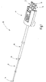
- a cryoprobe 10 is illustrated which is set up for endoscopic use.
- the cryoprobe 10 has a fluid connector 11 with connector pins 12, 13, 14, via which liquid or gaseous fluids are discharged to and from the cryoprobe 10.
- a coaxial fluid guide arrangement 15 leads to a fluid connection device, which is preferably formed by a connection piece 16.
- a second fluid guide arrangement 17 extends away from the connecting piece 16 in the distal direction.
- An effector for example a cryohead 18 , is arranged at the distal end of the second fluid guide arrangement 17 .
- the representation in figure 1 is not to scale - the length of the first fluid guide arrangement 15 can be up to several meters.
- the length of the second fluid guiding arrangement can also be considerable and range from a few decimeters to over a meter. The specific length depends on the desired application.
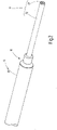
- the two fluid guide assemblies 15, 17 are coaxial assemblies, as can be seen from the figures 2 and 3 results.
- the first fluid guide arrangement 15 includes a first inner line 19 and a first outer line 20, preferably made of UV-transparent plastic.
- the inner line 19 extends through the lumen of the outer line 20, with the diameter of the lumen of the outer line 20 being significantly larger than the outer diameter of the first inner line 19.
- the inner line 19 lies with play within the lumen of the first outer line 20.
- a coaxial arrangement is also referred to when the inner line 19 is not located in the center of the outer line.
- the second fluid-guiding arrangement 17 which includes a second inner line 21 and a second outer line 22, which are arranged coaxially with one another are.
- the first inner line 19 is connected to one of the connector pins 12 to 14 of the fluid connector 11 .
- the first fluid guiding line 20 is connected to another of the connector pins 12 to 14 .
- the free flow cross sections of the first inner line 19 and the first outer line 20 are significantly larger than the free flow cross sections of the second inner line 21 and the second outer line 22.
- the outer diameter of the second fluid guide arrangement 17 is preferably significantly smaller than the outer diameter of the first fluid guide arrangement 15.
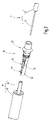
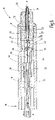
- the fluid connector goes out before assembly figure 3 as well as in the assembled state from the figures 4 and 5 out.
- the connecting piece 16 which is preferably made of UV-transparent plastic and has a socket-like section that forms an outer line socket 23 .
- This has a collar 24 which delimits an outer peripheral surface 25 ending at a collar 24 , which forms a seat for the first outer line 20 .
- the outer peripheral surface 25 can be cylindrical or, as shown, structured by having a plurality of grooves 26, preferably running in the circumferential direction, and optionally one or more ribs 27, the sawtooth profile of which allows the outer line 20 to be pushed onto the outer peripheral surface 25, but which prevents it from being pulled off .
- a radial passage 28 extends from the outer peripheral surface 25 to an axial passage opening 29, which receives the second outer pipe 22 and forms a seat for it.
- the through-opening 29 extends up to a step 30 at which the diameter of the through-opening 29 is reduced somewhat.
- the reduced inner diameter is significantly larger than the outer diameter of the second inner line 21, preferably at least as large as the inner diameter of the second outer line 22.
- a capillary gap is formed between the inner surface of the passage opening 29 and the outer surface of the second outer line 22, the width of which is dimensioned such that curable adhesive filled into the passage 28 pulls into the gap formed and forms a meniscus at the distal end of the passage opening 29 , without running out.
- the second inner duct 21 protrudes from the proximal end of the second outer duct 22 and extends up to the distal end of the first inner line 19, which in turn is clearly surmounted by the first outer line 20.
- the distal end of the first inner lead 19 is received in an inner lead socket 32 which is connected to the outer lead socket 23 via one or more spacers 33 .
- the inner line socket 32 is formed by a tubular section, the inner diameter of which is slightly larger than the outer diameter of the first inner line 19.
- the tubular section of the inner line socket 32 transitions at an annular shoulder 34 into a trough section 35 which has an adhesive filling opening 36 and towards the Spacer 33 is closed by a wall 37.
- This has an opening 38 whose diameter is preferably significantly larger than the diameter of the second inner line 21 .
- the diameter of the opening 38 is preferably at least as large as the inner diameter of the annular shoulder 34.
- a particularly simple injection molding tool for producing the connecting piece 16 can be constructed as an injection molded part.
- the second inner line 21 extends through this opening 38 and through the trough section 35 and into or through the inner line socket 32.
- the inner line socket 32 at least preferably has an adhesive filling opening 39 which breaks through the wall of the tubular inner line socket 32 in the radial direction and is preferably adjacent to the adhesive filling opening 36 .
- a capillary gap is preferably formed between the inner surface of the inner line mount 32 and the outer surface of the first inner line 19, the width of which is dimensioned such that adhesive is drawn into the capillary gap without running out.
- the adhesive forms a corresponding meniscus on the proximal face of inner lead socket 32 .
- the inside diameter of the first inner line 19 and the outside diameter of the second inner line 21 are matched to one another in such a way that the preferably cylindrical annular gap formed between them in the trough section 35 receives adhesive 41 without it reaching the proximal end of the second inner line 21 or closing it.
- the diameter of the opening 38 is preferably also dimensioned such that an uncontrolled outflow of the adhesive 41 from the trough section 35 after the latter has been filled with liquid adhesive is prevented.
- the second fluid guide arrangement 17 is first introduced until the second inner line 21 protrudes through the inner line socket 32 and the second outer line 22 rests against the step 30 . Furthermore, the first fluid guide arrangement 15 is attached to the fluid connection device by pushing the first inner line 19 onto the second inner line 21 and inserting it into the inner line holder 32 up to the stop formed by the annular shoulder 34 . Adhesive 31, 40, 41 is now filled into the passage 28 and into the adhesive filling openings 36, 39. The adhesive wets the inner surface of the through opening 29 and the outer surface of the second outer line 22. In addition, the adhesive 40 wets the outer surface of the first inner line 19 and the inner surface of the inner line socket 32.
- the adhesive 41 filled in via the adhesive filling opening 36 wets the outer surface of the second inner line 21 and penetrates into the space between the two inner lines 19, 21. Further adhesive is applied to the grooves 26 or the outer peripheral surface 25, after which the first outer line 20 is applied to the outer peripheral surface 25 is postponed. Then the adhesive 31, 40, 41 is caused to harden. This can preferably be done with UV radiation.
- the first outer line 20 and/or the fluid connection device ie the plastic from which this injection-molded part is made, is designed to be UV-transmissive and/or UV-light-conducting.
- the fluid connection device consists of a single plastic injection-molded part, which accommodates a coaxial first fluid guide arrangement 15 and a second fluid guide arrangement 17, which is also coaxial, and provides a plurality of adhesive reservoirs that allow the two fluid guide arrangements 15, 17 to be bonded to one another in a pressure-tight, process-reliable manner.
- the fluid connection device is characterized by a high level of functional integration in just one component, namely the connection piece 16 .
- the connecting piece 16 and the adhesive connection a mechanically tensile connection of the two fluid-guiding arrangements 15, 17 to one another is achieved.
- FIG. 12 illustrates a modified embodiment of the fluid connection device according to the invention, to which the above description applies accordingly.
- this embodiment has a barrier 42 arranged on the second inner line 21, which is held on the inner line 21 by friction and is formed, for example, by a rubber or plastic disk. During the joining process, the barrier 42 rests against the opening 38 and prevents adhesive from leaking out there during the gluing process. After the same has hardened, the barrier 42 has no function.
- FIG. 7 A further modified embodiment of the fluid connection device according to the invention is figure 7 illustrated.
- the opening 38 can be narrower than the annular shoulder 34 and also narrower than the through-opening 29 .
- the opening 38 can be designed like a funnel, ie widening conically towards the opening 29, in order to facilitate the introduction of the second inner line 21 into the connecting piece 16 on the one hand and the handling of the gluing process on the other.
- Each of the fluid connection devices described above has only a few (namely four) interfaces that have to be connected and sealed, which is preferably done by extensive gluing.
- the structure only requires a small amount of coordination in terms of matching the dimensions and dimensions of parts to one another.
- the connecting device according to the invention allows quick assembly and low assembly costs. This leads to reduced product costs due to low costs for the necessary parts. Finally, the dimensions and weight of the connecting device are reduced.
- the invention allows the use of a simple sealing and connection technique, in particular gluing (for example by means of UV-curing adhesives, the use of the capillary effect to fill the adhesive gap).
- gluing for example by means of UV-curing adhesives, the use of the capillary effect to fill the adhesive gap.
- the parts used in particular the inner lines 19, 21 and the outer lines 20, 22, are subject to lower accuracy requirements.
- the inner lines 19, 21 can be pushed far into one another in the axial direction (eg several centimeters). This also prevents adhesive from running into the open end of the second inner line 21 when the end between the two inner lines 19, 21 formed adhesive gap has a larger gap width than should ideally be provided. Again, less precise parts are required.
- plastics instead of metals allows for lower part and material costs, particularly as a result of the use of plastic injection molded parts.
- cryoprobe 11 fluid connector 12, 13, 14 connector pins 15 first fluid guide arrangement 16 Connector / fluid connector 17 second fluid guide arrangement 18 cryohead 19 first inner line 20 first outside line 21 second inner line 22 second external line 23 outdoor line socket 24 Federation 25 outer peripheral surface 26 grooves 27 rib 28 radial passage 29 axial through hole 30 step 31 adhesive 32 inner line fitting 33 spacers 34 ring shoulder 35 tub section 36 Adhesive Filling Port 37 Wall 38 opening 39 Adhesive Filling Port 40, 41 adhesive 42 barrier
Landscapes
- Health & Medical Sciences (AREA)
- Engineering & Computer Science (AREA)
- Mechanical Engineering (AREA)
- Surgery (AREA)
- Life Sciences & Earth Sciences (AREA)
- Nuclear Medicine, Radiotherapy & Molecular Imaging (AREA)
- Public Health (AREA)
- Heart & Thoracic Surgery (AREA)
- Medical Informatics (AREA)
- Molecular Biology (AREA)
- Animal Behavior & Ethology (AREA)
- General Health & Medical Sciences (AREA)
- Biomedical Technology (AREA)
- Veterinary Medicine (AREA)
- Otolaryngology (AREA)
- Physics & Mathematics (AREA)
- Electromagnetism (AREA)
- Toxicology (AREA)
- Chemical & Material Sciences (AREA)
- Chemical Kinetics & Catalysis (AREA)
- General Chemical & Material Sciences (AREA)
- Infusion, Injection, And Reservoir Apparatuses (AREA)
- Endoscopes (AREA)
- Surgical Instruments (AREA)
- Arrangements For Transmission Of Measured Signals (AREA)
Claims (14)
- Instrument ou sonde, notamment pour une application endoscopique,comprenant un premier ensemble de guidage de fluide (15) coaxial, qui présente un premier diamètre extérieur et comporte une première conduite intérieure (19) et une première conduite extérieure (20) dont l'extrémité dépasse par rapport à l'extrémité de la première conduite intérieure (19),comprenant un deuxième ensemble de guidage de fluide (17) coaxial, qui présente un deuxième diamètre extérieur et comporte une deuxième conduite extérieure (22) et une deuxième conduite intérieure (21),l'extrémité de la deuxième conduite intérieure (21) dépassant par rapport à l'extrémité de la deuxième conduite extérieure (22) et s'étendant dans la première conduite intérieure (19) et étant reliée à celle-ci,caractérisé en ce qu'il comprend une pièce de raccordement (16) destinée à relier le premier ensemble de guidage de fluide (15) au deuxième ensemble de guidage de fluide (17),les extrémités des deux conduites extérieures (20, 22) étant reliées l'une à l'autre par l'intermédiaire d'un élément de sertissage de conduites extérieures (23) de la pièce de raccordement (16),l'élément de sertissage de conduites extérieures (23) présentant une surface périphérique extérieure (25) sur laquelle est maintenue la première conduite extérieure (20).
- Instrument selon la revendication 1, caractérisé en ce que la première conduite extérieure (20) est collée à la surface périphérique extérieure (25) de l'élément de sertissage de conduites extérieures (23).
- Instrument selon l'une des revendications précédentes, caractérisé en ce que l'élément de sertissage de conduites extérieures (23) présente une ouverture (29) dans laquelle est maintenue la deuxième conduite extérieure (22).
- Instrument selon la revendication 4, caractérisé en ce que la deuxième conduite extérieure (22) est collée à une surface intérieure de l'ouverture (29).
- Instrument selon l'une des revendications 2 ou 3 et 5, caractérisé en ce que l'élément de sertissage de conduites extérieures (23) présente un passage (28) qui s'étend de la surface périphérique extérieure (25) vers la surface intérieure de l'ouverture (29).
- Instrument selon la revendication 5, caractérisé en ce que le passage (28) est un réservoir d'adhésif.
- Instrument selon l'une des revendications précédentes, caractérisé en ce que la deuxième conduite extérieure (22) s'étend avec son extrémité dans la première conduite extérieure (20).
- Instrument selon l'une des revendications précédentes, caractérisé en ce que la première conduite intérieure (19) et la deuxième conduite intérieure (21) sont collées l'une à l'autre.
- Instrument selon l'une des revendications précédentes, caractérisé en ce que la pièce de raccordement (16) présente un élément de sertissage de conduites intérieures (32) dans lequel est sertie la première conduite intérieure (19).
- Instrument selon la revendication 9, caractérisé en ce que l'élément de sertissage de conduites intérieures (32) présente un logement pour la première conduite intérieure (19), le logement présentant une ouverture de remplissage d'adhésif (39) qui est reliée à la surface extérieure de la première conduite intérieure (19) et est réalisée comme réservoir d'adhésif.
- Instrument selon l'une des revendications précédentes, caractérisé en ce que la pièce de raccordement (16) présente un élément de sertissage de conduites intérieures (32) dans lequel est sertie la deuxième conduite intérieure (21).
- Instrument selon la revendication 11, caractérisé en ce que l'élément de sertissage de conduites intérieures (32) présente un espace de réception d'adhésif (35) à travers lequel s'étend la deuxième conduite intérieure (21) et qui est relié à la première conduite intérieure (19).
- Instrument selon la revendication 9 ou 11, caractérisé en ce que la pièce de raccordement (16) présente un élément d'espacement (33) qui est relié à l'élément de sertissage de conduites intérieures (32).
- Instrument selon l'une des revendications précédentes, caractérisé en ce que l'instrument est une cryosonde (10).
Priority Applications (8)
| Application Number | Priority Date | Filing Date | Title |
|---|---|---|---|
| PL17155740T PL3360496T3 (pl) | 2017-02-10 | 2017-02-10 | Urządzenie do połączenia płynowego i kriosonda z takim urządzeniem |
| EP17155740.8A EP3360496B1 (fr) | 2017-02-10 | 2017-02-10 | Raccordement de fluide et cryosonde le comprenant |
| BR102017027706-2A BR102017027706B1 (pt) | 2017-02-10 | 2017-12-21 | Sistema de conexão de fluido e sonda cirúrgica criogênica com o mesmo |
| JP2018010714A JP7045203B2 (ja) | 2017-02-10 | 2018-01-25 | 流体接続システムおよびそれを用いた凍結プローブ |
| KR1020180009736A KR102471300B1 (ko) | 2017-02-10 | 2018-01-26 | 유체 연결 시스템 및 이를 구비한 극저온 프로브 |
| US15/891,901 US10864032B2 (en) | 2017-02-10 | 2018-02-08 | Fluid connecting system and cryoprobe with same |
| RU2018105019A RU2751967C2 (ru) | 2017-02-10 | 2018-02-09 | Устройство проточного сообщения и криозонд с таким устройством проточного сообщения |
| CN201810135300.9A CN108403205B (zh) | 2017-02-10 | 2018-02-09 | 流体连接系统及具有流体连接系统的冷冻探针 |
Applications Claiming Priority (1)
| Application Number | Priority Date | Filing Date | Title |
|---|---|---|---|
| EP17155740.8A EP3360496B1 (fr) | 2017-02-10 | 2017-02-10 | Raccordement de fluide et cryosonde le comprenant |
Publications (2)
| Publication Number | Publication Date |
|---|---|
| EP3360496A1 EP3360496A1 (fr) | 2018-08-15 |
| EP3360496B1 true EP3360496B1 (fr) | 2022-04-06 |
Family
ID=58043902
Family Applications (1)
| Application Number | Title | Priority Date | Filing Date |
|---|---|---|---|
| EP17155740.8A Active EP3360496B1 (fr) | 2017-02-10 | 2017-02-10 | Raccordement de fluide et cryosonde le comprenant |
Country Status (7)
| Country | Link |
|---|---|
| US (1) | US10864032B2 (fr) |
| EP (1) | EP3360496B1 (fr) |
| JP (1) | JP7045203B2 (fr) |
| KR (1) | KR102471300B1 (fr) |
| CN (1) | CN108403205B (fr) |
| PL (1) | PL3360496T3 (fr) |
| RU (1) | RU2751967C2 (fr) |
Families Citing this family (2)
| Publication number | Priority date | Publication date | Assignee | Title |
|---|---|---|---|---|
| WO2026084834A1 (fr) * | 2024-10-15 | 2026-04-23 | Boston Scientific Scimed, Inc. | Aiguille de cryoablation pour connecteur de console |
| WO2026084842A1 (fr) * | 2024-10-15 | 2026-04-23 | Boston Scientific Scimed, Inc. | Connecteur d'ensemble aiguille à ligne de cryoablation |
Citations (1)
| Publication number | Priority date | Publication date | Assignee | Title |
|---|---|---|---|---|
| EP1433990A1 (fr) * | 2002-12-26 | 2004-06-30 | Calsonic Kansei Corporation | Tuyau flexible |
Family Cites Families (39)
| Publication number | Priority date | Publication date | Assignee | Title |
|---|---|---|---|---|
| US3439680A (en) | 1965-04-12 | 1969-04-22 | Univ Northwestern | Surgical instrument for cataract removal |
| US3536075A (en) | 1967-08-01 | 1970-10-27 | Univ Northwestern | Cryosurgical instrument |
| US3841671A (en) * | 1973-10-30 | 1974-10-15 | Gen Motors Corp | Coaxial fluid lines with plug-in connector assemblies |
| CN1038220A (zh) * | 1988-03-07 | 1989-12-27 | 利奥卡有限公司 | 带容易控制的可更换的引导线的极小型外廓血管成型术气囊导管 |
| US4884573A (en) * | 1988-03-07 | 1989-12-05 | Leocor, Inc. | Very low profile angioplasty balloon catheter with capacity to use steerable, removable guidewire |
| CN1030559C (zh) | 1988-06-08 | 1995-12-27 | 程慧雄 | 转鼓内滤式放射型真空连续过滤机 |
| US5047045A (en) * | 1989-04-13 | 1991-09-10 | Scimed Life Systems, Inc. | Multi-section coaxial angioplasty catheter |
| US5344395A (en) * | 1989-11-13 | 1994-09-06 | Scimed Life Systems, Inc. | Apparatus for intravascular cavitation or delivery of low frequency mechanical energy |
| US5334162A (en) * | 1993-03-15 | 1994-08-02 | Eli Lilly And Company | Cartridge assembly for a lyophilized compound forming a disposable portion of an injector pen and method for same |
| US5916213A (en) | 1997-02-04 | 1999-06-29 | Medtronic, Inc. | Systems and methods for tissue mapping and ablation |
| US5846235A (en) | 1997-04-14 | 1998-12-08 | Johns Hopkins University | Endoscopic cryospray device |
| US20030028182A1 (en) * | 1999-04-21 | 2003-02-06 | Cryocath Technologies Inc. | Cryoablation catheter handle |
| DE10128701B4 (de) * | 2001-06-07 | 2005-06-23 | Celon Ag Medical Instruments | Sondenanordnung |
| US6767346B2 (en) | 2001-09-20 | 2004-07-27 | Endocare, Inc. | Cryosurgical probe with bellows shaft |
| US6858025B2 (en) * | 2002-08-06 | 2005-02-22 | Medically Advanced Designs, Llc | Cryo-surgical apparatus and method of use |
| US7189228B2 (en) | 2003-06-25 | 2007-03-13 | Endocare, Inc. | Detachable cryosurgical probe with breakaway handle |
| FI20045456L (fi) * | 2004-11-24 | 2006-05-25 | Wallac Oy | Lävistystyökalu biologisen näytepalan ottamiseksi |
| PT1848913E (pt) * | 2005-02-14 | 2013-10-16 | Borla Ind | Conector de fluido equipado com uma válvula |
| CN100408001C (zh) | 2005-04-14 | 2008-08-06 | 北京库蓝医疗设备有限公司 | 一次性使用的冷冻探针 |
| US20070191732A1 (en) | 2006-02-10 | 2007-08-16 | Voegele James W | Cryogenic probe |
| US20070241560A1 (en) * | 2006-04-18 | 2007-10-18 | Malone David S | Coaxial quick connector |
| ES2787354T3 (es) | 2008-06-11 | 2020-10-15 | Cryoconcepts Lp | Métodos de uso crioquirúrgicos |
| US8251987B2 (en) | 2008-08-28 | 2012-08-28 | Vivant Medical, Inc. | Microwave antenna |
| US9332973B2 (en) * | 2008-10-01 | 2016-05-10 | Covidien Lp | Needle biopsy device with exchangeable needle and integrated needle protection |
| DE202009018056U1 (de) * | 2009-04-16 | 2010-12-30 | Erbe Elektromedizin Gmbh | Endoskopisches Chirurgieinstrument |
| US20130207383A1 (en) * | 2009-12-15 | 2013-08-15 | Georg Fischer Llc | Containment Pipe Fittings and Methods |
| US9023033B2 (en) | 2010-08-04 | 2015-05-05 | St. Jude Medical, Atrial Fibrillation Division, Inc. | Magnetically guided catheters |
| US8986303B2 (en) | 2010-11-09 | 2015-03-24 | Biosense Webster, Inc. | Catheter with liquid-cooled control handle |
| CN105920717B (zh) | 2011-05-27 | 2019-05-21 | 科纳维医疗有限公司 | 具有流体旋转接头的医疗探针 |
| US8992413B2 (en) | 2011-05-31 | 2015-03-31 | Covidien Lp | Modified wet tip antenna design |
| CN107669332B (zh) | 2013-11-01 | 2020-09-18 | 美国宾得公司 | 低温消融导管、手柄组件以及低温球囊消融系统 |
| US10463417B2 (en) | 2014-09-17 | 2019-11-05 | Medtronic Cryocath Lp | Universal adaptor for gas scavenging systems |
| CN204797985U (zh) | 2015-07-09 | 2015-11-25 | 宁波胜杰康生物科技有限公司 | 一种新型肿瘤冷冻消融导管 |
| US10449332B2 (en) * | 2015-08-05 | 2019-10-22 | Biosense Webster (Israel) Ltd. | Guide wire luer hub |
| CN105943159B (zh) | 2016-05-16 | 2019-07-23 | 安隽医疗科技(南京)有限公司 | 一种可调式注水消融电极针 |
| WO2017200830A1 (fr) * | 2016-05-17 | 2017-11-23 | Q Holding Company | Ensemble de tubulure et de jonction et son procédé de fabrication |
| CN105852932B (zh) * | 2016-06-23 | 2018-01-19 | 天津大学 | 一种流体驱动的血管内斑块清除装置 |
| CN106264721B (zh) | 2016-08-29 | 2019-01-11 | 安隽医疗科技(南京)有限公司 | 一种冷循环消融针系统 |
| CN106264707B (zh) | 2016-09-28 | 2018-08-21 | 康沣生物科技(上海)有限公司 | 冷冻消融快速接头 |
-
2017
- 2017-02-10 EP EP17155740.8A patent/EP3360496B1/fr active Active
- 2017-02-10 PL PL17155740T patent/PL3360496T3/pl unknown
-
2018
- 2018-01-25 JP JP2018010714A patent/JP7045203B2/ja active Active
- 2018-01-26 KR KR1020180009736A patent/KR102471300B1/ko active Active
- 2018-02-08 US US15/891,901 patent/US10864032B2/en active Active
- 2018-02-09 RU RU2018105019A patent/RU2751967C2/ru active
- 2018-02-09 CN CN201810135300.9A patent/CN108403205B/zh active Active
Patent Citations (1)
| Publication number | Priority date | Publication date | Assignee | Title |
|---|---|---|---|---|
| EP1433990A1 (fr) * | 2002-12-26 | 2004-06-30 | Calsonic Kansei Corporation | Tuyau flexible |
Also Published As
| Publication number | Publication date |
|---|---|
| US10864032B2 (en) | 2020-12-15 |
| JP7045203B2 (ja) | 2022-03-31 |
| CN108403205B (zh) | 2021-08-17 |
| RU2018105019A3 (fr) | 2020-12-15 |
| US20180228526A1 (en) | 2018-08-16 |
| KR20180092835A (ko) | 2018-08-20 |
| EP3360496A1 (fr) | 2018-08-15 |
| JP2018126502A (ja) | 2018-08-16 |
| RU2018105019A (ru) | 2019-08-09 |
| BR102017027706A2 (pt) | 2018-11-21 |
| KR102471300B1 (ko) | 2022-11-29 |
| CN108403205A (zh) | 2018-08-17 |
| PL3360496T3 (pl) | 2022-06-06 |
| RU2751967C2 (ru) | 2021-07-21 |
| BR102017027706A8 (pt) | 2023-03-28 |
Similar Documents
| Publication | Publication Date | Title |
|---|---|---|
| DE3722904C2 (fr) | ||
| DE2601993A1 (de) | Kanuelenanordnung | |
| EP2545315B1 (fr) | Dispositif pour l'assemblage d'une conduite transportant un fluide à une pièce adjacente | |
| EP3360496B1 (fr) | Raccordement de fluide et cryosonde le comprenant | |
| EP3217057B1 (fr) | Dispositif et procédé de fixation destiné à rendre étanche un passage de conduite dans une cloison d'un bâtiment | |
| EP3846697B1 (fr) | Instrument chirurgical destiné à introduire de façon orientée une substance thérapeutique dans une cavité et outil s'y rapportant | |
| DE29516077U1 (de) | Sprühvorrichtung | |
| DE102017119704B4 (de) | Leitungskupplung und Behälter hiermit | |
| DE102011082470A1 (de) | Fitting mit lokaler Kapillarweitenanpassung | |
| DE10162455A1 (de) | Staubsaugerteil | |
| DE102011009909B4 (de) | Einrichtung zum Führen eines Kabels in einer medizintechnischen Dosiervorrichtung, Dosiereinrichtung sowie Behandlungsvorrichtung | |
| DE102009033365B4 (de) | Rückschlagventil | |
| EP3034124B1 (fr) | Systeme de tuyau pour l'application medicale | |
| DE102007030935B4 (de) | Verfahren zum Verbinden eines Rohres mit einer Rohrmuffe | |
| DE4025503A1 (de) | Injektionsvorrichtung | |
| EP2457610A1 (fr) | Adaptateur Luer-Lock doté d'un raccordement de cathéter et son procédé de fabrication | |
| DE102017206154A1 (de) | Schlauchleitung und Verfahren zu deren Herstellung | |
| DE102022211360A1 (de) | Medizinischer Fluid-Konnektor | |
| DE102016219083A1 (de) | Sondeneinrichtung zum Einführen in einen Patientenkörper sowie Schlauch/Konnektor-Baugruppe | |
| DE102016210653A1 (de) | Schlauch/Konnektor-Baugruppe | |
| DE19734689A1 (de) | Anordnung zur Verbindung einer rohr- oder schlauchförmigen Leitung aus Kunststoff mit einem Stahlrohrabschnitt | |
| DE8700434U1 (de) | Injektionseinrichtung mit Doppelkanüle für ein Endoskop | |
| WO2022106528A1 (fr) | Pointe de cathéter souple | |
| DE102017126428A1 (de) | Katheter zur Injektion und/oder Applikation eines Fluids | |
| DE202010012714U1 (de) | Katheter |
Legal Events
| Date | Code | Title | Description |
|---|---|---|---|
| PUAI | Public reference made under article 153(3) epc to a published international application that has entered the european phase |
Free format text: ORIGINAL CODE: 0009012 |
|
| STAA | Information on the status of an ep patent application or granted ep patent |
Free format text: STATUS: THE APPLICATION HAS BEEN PUBLISHED |
|
| AK | Designated contracting states |
Kind code of ref document: A1 Designated state(s): AL AT BE BG CH CY CZ DE DK EE ES FI FR GB GR HR HU IE IS IT LI LT LU LV MC MK MT NL NO PL PT RO RS SE SI SK SM TR |
|
| AX | Request for extension of the european patent |
Extension state: BA ME |
|
| STAA | Information on the status of an ep patent application or granted ep patent |
Free format text: STATUS: REQUEST FOR EXAMINATION WAS MADE |
|
| 17P | Request for examination filed |
Effective date: 20181206 |
|
| RBV | Designated contracting states (corrected) |
Designated state(s): AL AT BE BG CH CY CZ DE DK EE ES FI FR GB GR HR HU IE IS IT LI LT LU LV MC MK MT NL NO PL PT RO RS SE SI SK SM TR |
|
| STAA | Information on the status of an ep patent application or granted ep patent |
Free format text: STATUS: EXAMINATION IS IN PROGRESS |
|
| 17Q | First examination report despatched |
Effective date: 20210419 |
|
| GRAP | Despatch of communication of intention to grant a patent |
Free format text: ORIGINAL CODE: EPIDOSNIGR1 |
|
| STAA | Information on the status of an ep patent application or granted ep patent |
Free format text: STATUS: GRANT OF PATENT IS INTENDED |
|
| RIC1 | Information provided on ipc code assigned before grant |
Ipc: B29C 65/54 20060101ALI20211105BHEP Ipc: B29C 65/48 20060101ALI20211105BHEP Ipc: B29L 23/00 20060101ALI20211105BHEP Ipc: B29C 65/14 20060101ALI20211105BHEP Ipc: B29C 65/00 20060101ALI20211105BHEP Ipc: A61M 25/00 20060101ALI20211105BHEP Ipc: A61B 18/02 20060101AFI20211105BHEP |
|
| INTG | Intention to grant announced |
Effective date: 20211214 |
|
| GRAS | Grant fee paid |
Free format text: ORIGINAL CODE: EPIDOSNIGR3 |
|
| GRAA | (expected) grant |
Free format text: ORIGINAL CODE: 0009210 |
|
| STAA | Information on the status of an ep patent application or granted ep patent |
Free format text: STATUS: THE PATENT HAS BEEN GRANTED |
|
| AK | Designated contracting states |
Kind code of ref document: B1 Designated state(s): AL AT BE BG CH CY CZ DE DK EE ES FI FR GB GR HR HU IE IS IT LI LT LU LV MC MK MT NL NO PL PT RO RS SE SI SK SM TR |
|
| REG | Reference to a national code |
Ref country code: GB Ref legal event code: FG4D Free format text: NOT ENGLISH |
|
| REG | Reference to a national code |
Ref country code: CH Ref legal event code: EP |
|
| REG | Reference to a national code |
Ref country code: AT Ref legal event code: REF Ref document number: 1480577 Country of ref document: AT Kind code of ref document: T Effective date: 20220415 |
|
| REG | Reference to a national code |
Ref country code: DE Ref legal event code: R096 Ref document number: 502017012885 Country of ref document: DE |
|
| REG | Reference to a national code |
Ref country code: IE Ref legal event code: FG4D Free format text: LANGUAGE OF EP DOCUMENT: GERMAN |
|
| REG | Reference to a national code |
Ref country code: LT Ref legal event code: MG9D |
|
| REG | Reference to a national code |
Ref country code: NL Ref legal event code: MP Effective date: 20220406 |
|
| PG25 | Lapsed in a contracting state [announced via postgrant information from national office to epo] |
Ref country code: NL Free format text: LAPSE BECAUSE OF FAILURE TO SUBMIT A TRANSLATION OF THE DESCRIPTION OR TO PAY THE FEE WITHIN THE PRESCRIBED TIME-LIMIT Effective date: 20220406 |
|
| PG25 | Lapsed in a contracting state [announced via postgrant information from national office to epo] |
Ref country code: SE Free format text: LAPSE BECAUSE OF FAILURE TO SUBMIT A TRANSLATION OF THE DESCRIPTION OR TO PAY THE FEE WITHIN THE PRESCRIBED TIME-LIMIT Effective date: 20220406 Ref country code: PT Free format text: LAPSE BECAUSE OF FAILURE TO SUBMIT A TRANSLATION OF THE DESCRIPTION OR TO PAY THE FEE WITHIN THE PRESCRIBED TIME-LIMIT Effective date: 20220808 Ref country code: NO Free format text: LAPSE BECAUSE OF FAILURE TO SUBMIT A TRANSLATION OF THE DESCRIPTION OR TO PAY THE FEE WITHIN THE PRESCRIBED TIME-LIMIT Effective date: 20220706 Ref country code: LT Free format text: LAPSE BECAUSE OF FAILURE TO SUBMIT A TRANSLATION OF THE DESCRIPTION OR TO PAY THE FEE WITHIN THE PRESCRIBED TIME-LIMIT Effective date: 20220406 Ref country code: HR Free format text: LAPSE BECAUSE OF FAILURE TO SUBMIT A TRANSLATION OF THE DESCRIPTION OR TO PAY THE FEE WITHIN THE PRESCRIBED TIME-LIMIT Effective date: 20220406 Ref country code: GR Free format text: LAPSE BECAUSE OF FAILURE TO SUBMIT A TRANSLATION OF THE DESCRIPTION OR TO PAY THE FEE WITHIN THE PRESCRIBED TIME-LIMIT Effective date: 20220707 Ref country code: FI Free format text: LAPSE BECAUSE OF FAILURE TO SUBMIT A TRANSLATION OF THE DESCRIPTION OR TO PAY THE FEE WITHIN THE PRESCRIBED TIME-LIMIT Effective date: 20220406 Ref country code: ES Free format text: LAPSE BECAUSE OF FAILURE TO SUBMIT A TRANSLATION OF THE DESCRIPTION OR TO PAY THE FEE WITHIN THE PRESCRIBED TIME-LIMIT Effective date: 20220406 Ref country code: BG Free format text: LAPSE BECAUSE OF FAILURE TO SUBMIT A TRANSLATION OF THE DESCRIPTION OR TO PAY THE FEE WITHIN THE PRESCRIBED TIME-LIMIT Effective date: 20220706 |
|
| PG25 | Lapsed in a contracting state [announced via postgrant information from national office to epo] |
Ref country code: RS Free format text: LAPSE BECAUSE OF FAILURE TO SUBMIT A TRANSLATION OF THE DESCRIPTION OR TO PAY THE FEE WITHIN THE PRESCRIBED TIME-LIMIT Effective date: 20220406 Ref country code: LV Free format text: LAPSE BECAUSE OF FAILURE TO SUBMIT A TRANSLATION OF THE DESCRIPTION OR TO PAY THE FEE WITHIN THE PRESCRIBED TIME-LIMIT Effective date: 20220406 Ref country code: IS Free format text: LAPSE BECAUSE OF FAILURE TO SUBMIT A TRANSLATION OF THE DESCRIPTION OR TO PAY THE FEE WITHIN THE PRESCRIBED TIME-LIMIT Effective date: 20220806 |
|
| REG | Reference to a national code |
Ref country code: DE Ref legal event code: R097 Ref document number: 502017012885 Country of ref document: DE |
|
| PG25 | Lapsed in a contracting state [announced via postgrant information from national office to epo] |
Ref country code: SM Free format text: LAPSE BECAUSE OF FAILURE TO SUBMIT A TRANSLATION OF THE DESCRIPTION OR TO PAY THE FEE WITHIN THE PRESCRIBED TIME-LIMIT Effective date: 20220406 Ref country code: SK Free format text: LAPSE BECAUSE OF FAILURE TO SUBMIT A TRANSLATION OF THE DESCRIPTION OR TO PAY THE FEE WITHIN THE PRESCRIBED TIME-LIMIT Effective date: 20220406 Ref country code: RO Free format text: LAPSE BECAUSE OF FAILURE TO SUBMIT A TRANSLATION OF THE DESCRIPTION OR TO PAY THE FEE WITHIN THE PRESCRIBED TIME-LIMIT Effective date: 20220406 Ref country code: EE Free format text: LAPSE BECAUSE OF FAILURE TO SUBMIT A TRANSLATION OF THE DESCRIPTION OR TO PAY THE FEE WITHIN THE PRESCRIBED TIME-LIMIT Effective date: 20220406 Ref country code: DK Free format text: LAPSE BECAUSE OF FAILURE TO SUBMIT A TRANSLATION OF THE DESCRIPTION OR TO PAY THE FEE WITHIN THE PRESCRIBED TIME-LIMIT Effective date: 20220406 Ref country code: CZ Free format text: LAPSE BECAUSE OF FAILURE TO SUBMIT A TRANSLATION OF THE DESCRIPTION OR TO PAY THE FEE WITHIN THE PRESCRIBED TIME-LIMIT Effective date: 20220406 |
|
| PLBE | No opposition filed within time limit |
Free format text: ORIGINAL CODE: 0009261 |
|
| STAA | Information on the status of an ep patent application or granted ep patent |
Free format text: STATUS: NO OPPOSITION FILED WITHIN TIME LIMIT |
|
| 26N | No opposition filed |
Effective date: 20230110 |
|
| PG25 | Lapsed in a contracting state [announced via postgrant information from national office to epo] |
Ref country code: AL Free format text: LAPSE BECAUSE OF FAILURE TO SUBMIT A TRANSLATION OF THE DESCRIPTION OR TO PAY THE FEE WITHIN THE PRESCRIBED TIME-LIMIT Effective date: 20220406 |
|
| PG25 | Lapsed in a contracting state [announced via postgrant information from national office to epo] |
Ref country code: SI Free format text: LAPSE BECAUSE OF FAILURE TO SUBMIT A TRANSLATION OF THE DESCRIPTION OR TO PAY THE FEE WITHIN THE PRESCRIBED TIME-LIMIT Effective date: 20220406 |
|
| PG25 | Lapsed in a contracting state [announced via postgrant information from national office to epo] |
Ref country code: MC Free format text: LAPSE BECAUSE OF FAILURE TO SUBMIT A TRANSLATION OF THE DESCRIPTION OR TO PAY THE FEE WITHIN THE PRESCRIBED TIME-LIMIT Effective date: 20220406 |
|
| REG | Reference to a national code |
Ref country code: CH Ref legal event code: PL |
|
| REG | Reference to a national code |
Ref country code: BE Ref legal event code: MM Effective date: 20230228 |
|
| PG25 | Lapsed in a contracting state [announced via postgrant information from national office to epo] |
Ref country code: LU Free format text: LAPSE BECAUSE OF NON-PAYMENT OF DUE FEES Effective date: 20230210 Ref country code: LI Free format text: LAPSE BECAUSE OF NON-PAYMENT OF DUE FEES Effective date: 20230228 Ref country code: CH Free format text: LAPSE BECAUSE OF NON-PAYMENT OF DUE FEES Effective date: 20230228 |
|
| REG | Reference to a national code |
Ref country code: IE Ref legal event code: MM4A |
|
| PG25 | Lapsed in a contracting state [announced via postgrant information from national office to epo] |
Ref country code: IE Free format text: LAPSE BECAUSE OF NON-PAYMENT OF DUE FEES Effective date: 20230210 |
|
| PG25 | Lapsed in a contracting state [announced via postgrant information from national office to epo] |
Ref country code: BE Free format text: LAPSE BECAUSE OF NON-PAYMENT OF DUE FEES Effective date: 20230228 |
|
| REG | Reference to a national code |
Ref country code: AT Ref legal event code: MM01 Ref document number: 1480577 Country of ref document: AT Kind code of ref document: T Effective date: 20230210 |
|
| PG25 | Lapsed in a contracting state [announced via postgrant information from national office to epo] |
Ref country code: AT Free format text: LAPSE BECAUSE OF NON-PAYMENT OF DUE FEES Effective date: 20230210 |
|
| PG25 | Lapsed in a contracting state [announced via postgrant information from national office to epo] |
Ref country code: AT Free format text: LAPSE BECAUSE OF NON-PAYMENT OF DUE FEES Effective date: 20230210 |
|
| PG25 | Lapsed in a contracting state [announced via postgrant information from national office to epo] |
Ref country code: BG Free format text: LAPSE BECAUSE OF FAILURE TO SUBMIT A TRANSLATION OF THE DESCRIPTION OR TO PAY THE FEE WITHIN THE PRESCRIBED TIME-LIMIT Effective date: 20220406 |
|
| PG25 | Lapsed in a contracting state [announced via postgrant information from national office to epo] |
Ref country code: BG Free format text: LAPSE BECAUSE OF FAILURE TO SUBMIT A TRANSLATION OF THE DESCRIPTION OR TO PAY THE FEE WITHIN THE PRESCRIBED TIME-LIMIT Effective date: 20220406 |
|
| PG25 | Lapsed in a contracting state [announced via postgrant information from national office to epo] |
Ref country code: CY Free format text: LAPSE BECAUSE OF FAILURE TO SUBMIT A TRANSLATION OF THE DESCRIPTION OR TO PAY THE FEE WITHIN THE PRESCRIBED TIME-LIMIT; INVALID AB INITIO Effective date: 20170210 |
|
| PG25 | Lapsed in a contracting state [announced via postgrant information from national office to epo] |
Ref country code: HU Free format text: LAPSE BECAUSE OF FAILURE TO SUBMIT A TRANSLATION OF THE DESCRIPTION OR TO PAY THE FEE WITHIN THE PRESCRIBED TIME-LIMIT; INVALID AB INITIO Effective date: 20170210 |
|
| PG25 | Lapsed in a contracting state [announced via postgrant information from national office to epo] |
Ref country code: TR Free format text: LAPSE BECAUSE OF FAILURE TO SUBMIT A TRANSLATION OF THE DESCRIPTION OR TO PAY THE FEE WITHIN THE PRESCRIBED TIME-LIMIT Effective date: 20220406 |
|
| PGFP | Annual fee paid to national office [announced via postgrant information from national office to epo] |
Ref country code: GB Payment date: 20260223 Year of fee payment: 10 |
|
| PGFP | Annual fee paid to national office [announced via postgrant information from national office to epo] |
Ref country code: DE Payment date: 20260220 Year of fee payment: 10 |
|
| PGFP | Annual fee paid to national office [announced via postgrant information from national office to epo] |
Ref country code: IT Payment date: 20260220 Year of fee payment: 10 |
|
| PGFP | Annual fee paid to national office [announced via postgrant information from national office to epo] |
Ref country code: FR Payment date: 20260227 Year of fee payment: 10 |
|
| PGFP | Annual fee paid to national office [announced via postgrant information from national office to epo] |
Ref country code: PL Payment date: 20260114 Year of fee payment: 10 |