EP3360805A1 - Dispositif de cerclage - Google Patents
Dispositif de cerclage Download PDFInfo
- Publication number
- EP3360805A1 EP3360805A1 EP18155242.3A EP18155242A EP3360805A1 EP 3360805 A1 EP3360805 A1 EP 3360805A1 EP 18155242 A EP18155242 A EP 18155242A EP 3360805 A1 EP3360805 A1 EP 3360805A1
- Authority
- EP
- European Patent Office
- Prior art keywords
- holder
- working position
- frame
- strapping device
- strapping
- Prior art date
- Legal status (The legal status is an assumption and is not a legal conclusion. Google has not performed a legal analysis and makes no representation as to the accuracy of the status listed.)
- Granted
Links
Images


Classifications
-
- B—PERFORMING OPERATIONS; TRANSPORTING
- B65—CONVEYING; PACKING; STORING; HANDLING THIN OR FILAMENTARY MATERIAL
- B65B—MACHINES, APPARATUS OR DEVICES FOR, OR METHODS OF, PACKAGING ARTICLES OR MATERIALS; UNPACKING
- B65B13/00—Bundling articles
- B65B13/18—Details of, or auxiliary devices used in, bundling machines or bundling tools
- B65B13/185—Details of tools
-
- B—PERFORMING OPERATIONS; TRANSPORTING
- B65—CONVEYING; PACKING; STORING; HANDLING THIN OR FILAMENTARY MATERIAL
- B65B—MACHINES, APPARATUS OR DEVICES FOR, OR METHODS OF, PACKAGING ARTICLES OR MATERIALS; UNPACKING
- B65B59/00—Arrangements to enable machines to handle articles of different sizes, to produce packages of different sizes, to vary the contents of packages, to handle different types of packaging material, or to give access for cleaning or maintenance purposes
- B65B59/04—Machines constructed with readily-detachable units or assemblies, e.g. to facilitate maintenance
-
- B—PERFORMING OPERATIONS; TRANSPORTING
- B65—CONVEYING; PACKING; STORING; HANDLING THIN OR FILAMENTARY MATERIAL
- B65H—HANDLING THIN OR FILAMENTARY MATERIAL, e.g. SHEETS, WEBS, CABLES
- B65H49/00—Unwinding or paying-out filamentary material; Supporting, storing or transporting packages from which filamentary material is to be withdrawn or paid-out
- B65H49/18—Methods or apparatus in which packages rotate
- B65H49/20—Package-supporting devices
- B65H49/26—Axial shafts or spigots
-
- B—PERFORMING OPERATIONS; TRANSPORTING
- B65—CONVEYING; PACKING; STORING; HANDLING THIN OR FILAMENTARY MATERIAL
- B65H—HANDLING THIN OR FILAMENTARY MATERIAL, e.g. SHEETS, WEBS, CABLES
- B65H49/00—Unwinding or paying-out filamentary material; Supporting, storing or transporting packages from which filamentary material is to be withdrawn or paid-out
- B65H49/18—Methods or apparatus in which packages rotate
- B65H49/20—Package-supporting devices
- B65H49/32—Stands or frameworks
-
- B—PERFORMING OPERATIONS; TRANSPORTING
- B65—CONVEYING; PACKING; STORING; HANDLING THIN OR FILAMENTARY MATERIAL
- B65B—MACHINES, APPARATUS OR DEVICES FOR, OR METHODS OF, PACKAGING ARTICLES OR MATERIALS; UNPACKING
- B65B27/00—Bundling particular articles presenting special problems using string, wire, or narrow tape or band; Baling fibrous material, e.g. peat, not otherwise provided for
- B65B27/08—Bundling paper sheets, envelopes, bags, newspapers, or other thin flat articles
-
- B—PERFORMING OPERATIONS; TRANSPORTING
- B65—CONVEYING; PACKING; STORING; HANDLING THIN OR FILAMENTARY MATERIAL
- B65H—HANDLING THIN OR FILAMENTARY MATERIAL, e.g. SHEETS, WEBS, CABLES
- B65H2301/00—Handling processes for sheets or webs
- B65H2301/40—Type of handling process
- B65H2301/41—Winding, unwinding
- B65H2301/413—Supporting web roll
- B65H2301/4132—Cantilever arrangement
- B65H2301/41322—Cantilever arrangement pivoting movement of roll support
- B65H2301/413226—Cantilever arrangement pivoting movement of roll support around an axis perpendicular to roll axis
-
- B—PERFORMING OPERATIONS; TRANSPORTING
- B65—CONVEYING; PACKING; STORING; HANDLING THIN OR FILAMENTARY MATERIAL
- B65H—HANDLING THIN OR FILAMENTARY MATERIAL, e.g. SHEETS, WEBS, CABLES
- B65H2701/00—Handled material; Storage means
- B65H2701/30—Handled filamentary material
- B65H2701/37—Tapes
- B65H2701/375—Strapping tapes
-
- B—PERFORMING OPERATIONS; TRANSPORTING
- B65—CONVEYING; PACKING; STORING; HANDLING THIN OR FILAMENTARY MATERIAL
- B65H—HANDLING THIN OR FILAMENTARY MATERIAL, e.g. SHEETS, WEBS, CABLES
- B65H2801/00—Application field
- B65H2801/81—Packaging machines
Definitions
- the holder can be pivoted out of the frame to the side in such a way that the bearing journal in this case is pivoted from its horizontal position in the direction of the vertical. He stands in non-working position therefore at an angle to the horizontal, ultimately oblique or maximum vertical thereto. As a result of this positioning of the journal in the non-working position consequently the tape roll for re-placement on the journal is no longer, as before, to hold quasi vertical respectively to position, but also tilted to maximum in the horizontal.
- the holder is according to an expedient development of the invention by an angle between 30 ° - 90 ° pivotable, preferably at an angle between 45 ° - 75 °.
- In the non-working position thus takes the bearing pin and thus the pivoted-out axis of rotation at an angle between 30 ° - 90 ° to the horizontal, preferably between 45 ° - 75 °.
- the touchdown is thus much more comfortable, not least as a result of the fact that the tape roll, as the horizontal tilted, can be used much easier. Because the operator can then easily engage the tape roll on a side cheek and lift, which is just not possible with a horizontal axis of rotation and thus vertically standing tape roll.
- the handle can be attached to the support frame itself.
- the support frame itself thus has a corresponding portion which forms a handle on which the operator can attack with the hand or the foot.
- an outer connecting strut is provided at the lower in the working position, horizontally extending frame struts, on the one hand connects the frame struts together and stiffened, but on the other hand simultaneously represents the handle to be used.
- This handle may be positioned to protrude laterally beyond the tape roll on the support frame so that the handle can be operated by either hand or foot.
- an expedient development of the invention provides that the holder frame is connected to at least one actuating element which builds up a restoring force when pivoting from the non-working position to the working position , If the support frame is swiveled back into the working position after the roll has been changed, then an actuating element coupled to the holding frame is actuated, which builds up a restoring force during this return pivoting movement.
- the actuator is therefore a force storage.
- At least one gas spring is used. This is fixed frame side with the cylinder or the piston, while the other part of the gas spring, so the piston or the cylinder, is arranged on the support frame.
- the respective fasteners are pivotally mounted, since the adjusting element during the pivoting movement performs a relative movement to both the frame and the support frame.
- the motorized adjusting device is preferably associated with a control device with associated operating element for controlling the setting device.
- the control device then controls the motorized control operation until reaching the respective end position.
- a locking device for locking the holder in the working position and / or the non-working position can be provided.
- the holder is locked in the respective position, so it can not solve automatically without opening the locking device from this position. This is on the one hand ensures that the holder always remains in the correct working position, therefore, so the tape can take place undisturbed.
- the non-working position is assigned a locking device, it is ensured that this position is also fixed for the strap change. If the gas spring is already sufficient for locking in the non-working position, then no additional locking device is to be provided. The gas spring can be overridden for pivoting by the weight of the tape roll and a lower effort on the part of the operator.
- the locking device regardless of whether it is assigned to the working position or the non-employment position, automatically closes upon reaching the working or the non-employment position. It can either be opened manually, ie it must be manually unlocked or released by the operator for pivoting. Alternatively, it is also conceivable that the locking device automatically opens by applying pressure for pivoting. Thus, if sufficiently strong pressed against the support for pivoting or worked on the part of the servomotor, the locking device, such as a latching device, opens automatically and releases the holder. In a corresponding manner, the locking device also snaps back automatically when the respective end position is reached.
- Fig. 1 shows in the form of a schematic diagram of a strapping device 1 according to the invention, comprising a frame 2 with a frame provided on the device 3 for conveying and retightening a tape 4, which is wound on a tape roll 5 and deducted from this.
- the device 3 for conveying and re-tensioning the belt comprises corresponding conveying and tensioning means for shooting the belt along a frame 6 and pulling it out of this frame and around a packaged goods 7 to be strapped tighten.
- a device 8 is provided for cutting and connecting the band ends of the clamped band section, usually in the form of a welding unit.
- the basic structure and function of such a strapping device is known.
- a holder 9 is further provided for the tape roll 5, which has a rotatably mounted bearing pin 10, on which the tape roll 5 is placed.
- the tape roll 5 is fixed accordingly, so that it sits firmly on the bearing pin 10 and a bearing plate associated therewith, for which purpose a corresponding, not shown in detail screw holder is provided.
- the holder 9 comprising a support frame 11 is arranged pivotably about a pivot axis 12 on the frame 2, so it can be pivoted out of the frame and into the frame.
- the tape roll 5 In the working position, the tape roll 5 is in the in Fig. 1 shown, quasi-vertical position within the frame 2, in the non-working position for role change, she is Mechanicalgeschwen from the frame.
- Fig. 2 shows the holder 9 in the pivoted working position.
- the tape roll 5 is vertical, that is, that the axis of rotation and thus the bearing pin 10 is horizontal.
- the bearing pin 10 assumes an angular position to the horizontal, wherein the angle between the bearing pin 10 respectively axis of rotation and the horizontal in Fig. 3 is marked with ⁇ .
- This angle is between preferably at least 30 ° and a maximum of 90 °, in the illustrated embodiment, the angle is about 70 °.
- the tape roll 5 can now be removed by releasing the roller fixing 13 from the bearing pin 10 and a new roll of tape 5 are placed.
- FIGS. 2 and 3 show the support frame 11 and the bracket 9 is connected to an actuator 14 in the form of a gas spring 15 which is fixed at one end to the frame 2 with the other end to the support frame 11.
- This actuator 14 respectively the gas spring 15 builds during pivoting of the in Fig. 3 shown non-working position along the arrow B in the in Fig. 2 shown working position on a restoring force that supports the re-pivoting movement along the arrow A in the non-working position.
- the restoring force is built up by compressing the gas spring 15, so it supports the operator when re-swinging.
- the support frame 11 consists of several frame struts. Shown are two upper frame struts 16, which is pivotally mounted on the frame 2 via corresponding bearing pins 17.
- the bearing pins 17 are rotatably received in corresponding bearing receivers 18 on the frame 2, for example via sliding or roller bearings.
- Fig. 1 arranged in principle connecting carrier 21, on which in turn the bearing pin 10 is arranged respectively rotatably mounted.
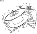
- the bearing pin 10 is connected to a bearing plate 22, see Fig. 5 on which the tape roll 5 is seated.
- the roll holder 13 here a screw toggle, unscrewed from the corresponding threaded portion of the journal 10, so that the tape roll 5 is released from the bearing pin 10. It can then be deducted due to the inclination of the journal 10 by a corresponding oblique movement.
- the holder 9 are, in Fig. 1 only shown in principle, associated with corresponding locking means 27 which make the locking of the holder 9 in the working position and / or the non-working position, so that the holder 9 is fixed in the respective end position and can not be moved unintentionally from this position.
- These locking devices 27 engage, for example, in the region of the axis of rotation 12, that is to say the bearing of the bearing pins 17 in the bearing receptacles 18. For example, they lock automatically when the working position and / or the non-working position is taken, depending on which position it is assigned, whereby both positions can be locked.
- These locking devices 27 may be either to be solved by the user, that is, the user must solve them manually before he makes the respective pivoting.
- the locking means 27 can be realized, for example, by means of a latching pin which engages in a corresponding latching receptacle, or in a similar manner.
- Fig. 6 shows in the form of a schematic representation of a partial view of a strapping device 1 according to the invention a further embodiment, in which case only a section of the frame 2 and the holder 9 is shown.
Landscapes
- Engineering & Computer Science (AREA)
- Mechanical Engineering (AREA)
- Basic Packing Technique (AREA)
Applications Claiming Priority (1)
| Application Number | Priority Date | Filing Date | Title |
|---|---|---|---|
| DE102017102853.6A DE102017102853B4 (de) | 2017-02-13 | 2017-02-13 | Umreifungsvorrichtung |
Publications (2)
| Publication Number | Publication Date |
|---|---|
| EP3360805A1 true EP3360805A1 (fr) | 2018-08-15 |
| EP3360805B1 EP3360805B1 (fr) | 2020-01-08 |
Family
ID=61167942
Family Applications (1)
| Application Number | Title | Priority Date | Filing Date |
|---|---|---|---|
| EP18155242.3A Active EP3360805B1 (fr) | 2017-02-13 | 2018-02-06 | Dispositif de cerclage |
Country Status (2)
| Country | Link |
|---|---|
| EP (1) | EP3360805B1 (fr) |
| DE (1) | DE102017102853B4 (fr) |
Citations (8)
| Publication number | Priority date | Publication date | Assignee | Title |
|---|---|---|---|---|
| US2195043A (en) * | 1939-01-03 | 1940-03-26 | Stanley Works | Wire tying machine |
| JPS5135488U (fr) * | 1974-09-04 | 1976-03-16 | ||
| JPS5168791U (fr) * | 1974-11-22 | 1976-05-31 | ||
| JPH0196804U (fr) * | 1987-12-21 | 1989-06-27 | ||
| EP0485097A1 (fr) * | 1990-11-07 | 1992-05-13 | Signode Corporation | Dispositif de distribution et d'accumulation d'un lien de cerclage et sa combinaison avec une machine de cerclage |
| EP1035020A1 (fr) * | 1999-03-10 | 2000-09-13 | Hiroshi c/o Taiyo Seiki Co. Ltd. Hataya | Machine de cerclage avec bande |
| EP1489006A2 (fr) * | 2003-06-20 | 2004-12-22 | Illinois Tool Works Inc. | Machine à cercler avec dispositif d'alimentation basculant |
| CH700613A2 (de) * | 2009-03-25 | 2010-09-30 | Tekpak Corp | Gerät mit herausführbarer Bandrolleneinheit. |
Family Cites Families (2)
| Publication number | Priority date | Publication date | Assignee | Title |
|---|---|---|---|---|
| US5444353A (en) * | 1992-06-16 | 1995-08-22 | Hitachi Koki Co., Ltd. | Battery charger |
| TWM364697U (en) | 2009-03-06 | 2009-09-11 | Tekpak Corp | Device with flappable strip plate set |
-
2017
- 2017-02-13 DE DE102017102853.6A patent/DE102017102853B4/de active Active
-
2018
- 2018-02-06 EP EP18155242.3A patent/EP3360805B1/fr active Active
Patent Citations (8)
| Publication number | Priority date | Publication date | Assignee | Title |
|---|---|---|---|---|
| US2195043A (en) * | 1939-01-03 | 1940-03-26 | Stanley Works | Wire tying machine |
| JPS5135488U (fr) * | 1974-09-04 | 1976-03-16 | ||
| JPS5168791U (fr) * | 1974-11-22 | 1976-05-31 | ||
| JPH0196804U (fr) * | 1987-12-21 | 1989-06-27 | ||
| EP0485097A1 (fr) * | 1990-11-07 | 1992-05-13 | Signode Corporation | Dispositif de distribution et d'accumulation d'un lien de cerclage et sa combinaison avec une machine de cerclage |
| EP1035020A1 (fr) * | 1999-03-10 | 2000-09-13 | Hiroshi c/o Taiyo Seiki Co. Ltd. Hataya | Machine de cerclage avec bande |
| EP1489006A2 (fr) * | 2003-06-20 | 2004-12-22 | Illinois Tool Works Inc. | Machine à cercler avec dispositif d'alimentation basculant |
| CH700613A2 (de) * | 2009-03-25 | 2010-09-30 | Tekpak Corp | Gerät mit herausführbarer Bandrolleneinheit. |
Also Published As
| Publication number | Publication date |
|---|---|
| DE102017102853B4 (de) | 2019-03-14 |
| EP3360805B1 (fr) | 2020-01-08 |
| DE102017102853A1 (de) | 2018-08-16 |
Similar Documents
| Publication | Publication Date | Title |
|---|---|---|
| DE69532217T2 (de) | Vorrichtung für die Handhabung von Matratzen | |
| DE3412125C1 (de) | Markise | |
| CH658029A5 (de) | Vorrichtung zum spannen, verschliessen und abschneiden von kunststoffbaendern fuer packstueckumreifungen. | |
| DE10112522C2 (de) | Wechselstation für Sleeves von Druckmaschinen | |
| EP3224037B1 (fr) | Compacteur à rouleau transportable | |
| EP3747643A2 (fr) | Dispositif d' alimentation de matière à presser pour une presse à balles verticale et presse à balles avec tel dispositif | |
| DE60318088T2 (de) | Koffervorrichtung für ein auto | |
| AT519070A1 (de) | Gerätehaltesystem sowie damit ausgestattetes Fahrzeug | |
| DE2757613A1 (de) | Schneidvorrichtung fuer eine stofflegemaschine | |
| DE102017102853B4 (de) | Umreifungsvorrichtung | |
| DE2923237C2 (de) | Feldhäcksler mit in einem Gehäuse angeordneter Schneidtrommel und Nachschleifvorrichtung | |
| DE2520463C3 (de) | Vorrichtung zum Ankleben des Zwickeinschlages an der Brandsohle von fest eingespanntem Schuhwerk | |
| DE19808390A1 (de) | Schneidvorrichtung für Papier, Folien o. dgl. | |
| DE3119954A1 (de) | "maehdrescher" | |
| DE102011110844B4 (de) | Vorrichtung an einer Spinnereivorbereitungsmaschine, insbesondere Strecke, Karde, Kämmmaschine o.dgl. mit einem Streckwerk | |
| DE1708374C (de) | Feststellvorrichtung für Falttüren | |
| DE2265250C3 (de) | Vorrichtung zum Klebezwicken von fest eingespanntem Schuhwerk | |
| DE2854928C2 (de) | Rolladen | |
| DE2944940C2 (de) | Vorrichtung zur seitlichen Abtrennung von benachbarten Viehständen | |
| CH674218A5 (fr) | ||
| DE9316974U1 (de) | Von Hand bewegbares Transportgerät | |
| DE854791C (de) | Maschine zum Abschneiden von Baendern auf gleiche Laenge | |
| DE567107C (de) | Vorrichtung zum selbsttaetigen Verriegeln des freien Endes des Auflagedornes einer Langfalzmaschine | |
| DE2639205A1 (de) | Gestell fuer eine darauf vorzugsweise abnehmbar und aufsetzbar angeordnete patientenunterlage | |
| DE2316335C3 (de) | Vorrichtung zum Einschlagen von Täcksen im Gelenkbereich von Schuhen |
Legal Events
| Date | Code | Title | Description |
|---|---|---|---|
| PUAI | Public reference made under article 153(3) epc to a published international application that has entered the european phase |
Free format text: ORIGINAL CODE: 0009012 |
|
| STAA | Information on the status of an ep patent application or granted ep patent |
Free format text: STATUS: THE APPLICATION HAS BEEN PUBLISHED |
|
| AK | Designated contracting states |
Kind code of ref document: A1 Designated state(s): AL AT BE BG CH CY CZ DE DK EE ES FI FR GB GR HR HU IE IS IT LI LT LU LV MC MK MT NL NO PL PT RO RS SE SI SK SM TR |
|
| AX | Request for extension of the european patent |
Extension state: BA ME |
|
| STAA | Information on the status of an ep patent application or granted ep patent |
Free format text: STATUS: REQUEST FOR EXAMINATION WAS MADE |
|
| 17P | Request for examination filed |
Effective date: 20190212 |
|
| RBV | Designated contracting states (corrected) |
Designated state(s): AL AT BE BG CH CY CZ DE DK EE ES FI FR GB GR HR HU IE IS IT LI LT LU LV MC MK MT NL NO PL PT RO RS SE SI SK SM TR |
|
| STAA | Information on the status of an ep patent application or granted ep patent |
Free format text: STATUS: EXAMINATION IS IN PROGRESS |
|
| 17Q | First examination report despatched |
Effective date: 20190328 |
|
| RIC1 | Information provided on ipc code assigned before grant |
Ipc: B65H 49/26 20060101ALI20190802BHEP Ipc: B65B 13/18 20060101AFI20190802BHEP Ipc: B65H 49/00 20060101ALI20190802BHEP Ipc: B65B 59/04 20060101ALI20190802BHEP Ipc: B65H 49/32 20060101ALI20190802BHEP Ipc: B65B 27/08 20060101ALN20190802BHEP |
|
| GRAP | Despatch of communication of intention to grant a patent |
Free format text: ORIGINAL CODE: EPIDOSNIGR1 |
|
| STAA | Information on the status of an ep patent application or granted ep patent |
Free format text: STATUS: GRANT OF PATENT IS INTENDED |
|
| INTG | Intention to grant announced |
Effective date: 20191002 |
|
| GRAS | Grant fee paid |
Free format text: ORIGINAL CODE: EPIDOSNIGR3 |
|
| GRAA | (expected) grant |
Free format text: ORIGINAL CODE: 0009210 |
|
| STAA | Information on the status of an ep patent application or granted ep patent |
Free format text: STATUS: THE PATENT HAS BEEN GRANTED |
|
| AK | Designated contracting states |
Kind code of ref document: B1 Designated state(s): AL AT BE BG CH CY CZ DE DK EE ES FI FR GB GR HR HU IE IS IT LI LT LU LV MC MK MT NL NO PL PT RO RS SE SI SK SM TR |
|
| REG | Reference to a national code |
Ref country code: GB Ref legal event code: FG4D Free format text: NOT ENGLISH |
|
| REG | Reference to a national code |
Ref country code: CH Ref legal event code: EP |
|
| REG | Reference to a national code |
Ref country code: DE Ref legal event code: R096 Ref document number: 502018000600 Country of ref document: DE |
|
| REG | Reference to a national code |
Ref country code: IE Ref legal event code: FG4D Free format text: LANGUAGE OF EP DOCUMENT: GERMAN |
|
| REG | Reference to a national code |
Ref country code: AT Ref legal event code: REF Ref document number: 1222406 Country of ref document: AT Kind code of ref document: T Effective date: 20200215 |
|
| REG | Reference to a national code |
Ref country code: NL Ref legal event code: MP Effective date: 20200108 |
|
| REG | Reference to a national code |
Ref country code: LT Ref legal event code: MG4D |
|
| PG25 | Lapsed in a contracting state [announced via postgrant information from national office to epo] |
Ref country code: NL Free format text: LAPSE BECAUSE OF FAILURE TO SUBMIT A TRANSLATION OF THE DESCRIPTION OR TO PAY THE FEE WITHIN THE PRESCRIBED TIME-LIMIT Effective date: 20200108 Ref country code: PT Free format text: LAPSE BECAUSE OF FAILURE TO SUBMIT A TRANSLATION OF THE DESCRIPTION OR TO PAY THE FEE WITHIN THE PRESCRIBED TIME-LIMIT Effective date: 20200531 Ref country code: NO Free format text: LAPSE BECAUSE OF FAILURE TO SUBMIT A TRANSLATION OF THE DESCRIPTION OR TO PAY THE FEE WITHIN THE PRESCRIBED TIME-LIMIT Effective date: 20200408 Ref country code: LT Free format text: LAPSE BECAUSE OF FAILURE TO SUBMIT A TRANSLATION OF THE DESCRIPTION OR TO PAY THE FEE WITHIN THE PRESCRIBED TIME-LIMIT Effective date: 20200108 Ref country code: RS Free format text: LAPSE BECAUSE OF FAILURE TO SUBMIT A TRANSLATION OF THE DESCRIPTION OR TO PAY THE FEE WITHIN THE PRESCRIBED TIME-LIMIT Effective date: 20200108 Ref country code: FI Free format text: LAPSE BECAUSE OF FAILURE TO SUBMIT A TRANSLATION OF THE DESCRIPTION OR TO PAY THE FEE WITHIN THE PRESCRIBED TIME-LIMIT Effective date: 20200108 |
|
| PG25 | Lapsed in a contracting state [announced via postgrant information from national office to epo] |
Ref country code: BG Free format text: LAPSE BECAUSE OF FAILURE TO SUBMIT A TRANSLATION OF THE DESCRIPTION OR TO PAY THE FEE WITHIN THE PRESCRIBED TIME-LIMIT Effective date: 20200408 Ref country code: LV Free format text: LAPSE BECAUSE OF FAILURE TO SUBMIT A TRANSLATION OF THE DESCRIPTION OR TO PAY THE FEE WITHIN THE PRESCRIBED TIME-LIMIT Effective date: 20200108 Ref country code: IS Free format text: LAPSE BECAUSE OF FAILURE TO SUBMIT A TRANSLATION OF THE DESCRIPTION OR TO PAY THE FEE WITHIN THE PRESCRIBED TIME-LIMIT Effective date: 20200508 Ref country code: SE Free format text: LAPSE BECAUSE OF FAILURE TO SUBMIT A TRANSLATION OF THE DESCRIPTION OR TO PAY THE FEE WITHIN THE PRESCRIBED TIME-LIMIT Effective date: 20200108 Ref country code: GR Free format text: LAPSE BECAUSE OF FAILURE TO SUBMIT A TRANSLATION OF THE DESCRIPTION OR TO PAY THE FEE WITHIN THE PRESCRIBED TIME-LIMIT Effective date: 20200409 Ref country code: HR Free format text: LAPSE BECAUSE OF FAILURE TO SUBMIT A TRANSLATION OF THE DESCRIPTION OR TO PAY THE FEE WITHIN THE PRESCRIBED TIME-LIMIT Effective date: 20200108 |
|
| REG | Reference to a national code |
Ref country code: DE Ref legal event code: R097 Ref document number: 502018000600 Country of ref document: DE |
|
| REG | Reference to a national code |
Ref country code: BE Ref legal event code: MM Effective date: 20200229 |
|
| PG25 | Lapsed in a contracting state [announced via postgrant information from national office to epo] |
Ref country code: DK Free format text: LAPSE BECAUSE OF FAILURE TO SUBMIT A TRANSLATION OF THE DESCRIPTION OR TO PAY THE FEE WITHIN THE PRESCRIBED TIME-LIMIT Effective date: 20200108 Ref country code: LU Free format text: LAPSE BECAUSE OF NON-PAYMENT OF DUE FEES Effective date: 20200206 Ref country code: SM Free format text: LAPSE BECAUSE OF FAILURE TO SUBMIT A TRANSLATION OF THE DESCRIPTION OR TO PAY THE FEE WITHIN THE PRESCRIBED TIME-LIMIT Effective date: 20200108 Ref country code: EE Free format text: LAPSE BECAUSE OF FAILURE TO SUBMIT A TRANSLATION OF THE DESCRIPTION OR TO PAY THE FEE WITHIN THE PRESCRIBED TIME-LIMIT Effective date: 20200108 Ref country code: MC Free format text: LAPSE BECAUSE OF FAILURE TO SUBMIT A TRANSLATION OF THE DESCRIPTION OR TO PAY THE FEE WITHIN THE PRESCRIBED TIME-LIMIT Effective date: 20200108 Ref country code: SK Free format text: LAPSE BECAUSE OF FAILURE TO SUBMIT A TRANSLATION OF THE DESCRIPTION OR TO PAY THE FEE WITHIN THE PRESCRIBED TIME-LIMIT Effective date: 20200108 Ref country code: CZ Free format text: LAPSE BECAUSE OF FAILURE TO SUBMIT A TRANSLATION OF THE DESCRIPTION OR TO PAY THE FEE WITHIN THE PRESCRIBED TIME-LIMIT Effective date: 20200108 Ref country code: RO Free format text: LAPSE BECAUSE OF FAILURE TO SUBMIT A TRANSLATION OF THE DESCRIPTION OR TO PAY THE FEE WITHIN THE PRESCRIBED TIME-LIMIT Effective date: 20200108 Ref country code: ES Free format text: LAPSE BECAUSE OF FAILURE TO SUBMIT A TRANSLATION OF THE DESCRIPTION OR TO PAY THE FEE WITHIN THE PRESCRIBED TIME-LIMIT Effective date: 20200108 |
|
| PLBE | No opposition filed within time limit |
Free format text: ORIGINAL CODE: 0009261 |
|
| STAA | Information on the status of an ep patent application or granted ep patent |
Free format text: STATUS: NO OPPOSITION FILED WITHIN TIME LIMIT |
|
| 26N | No opposition filed |
Effective date: 20201009 |
|
| PG25 | Lapsed in a contracting state [announced via postgrant information from national office to epo] |
Ref country code: IE Free format text: LAPSE BECAUSE OF NON-PAYMENT OF DUE FEES Effective date: 20200206 Ref country code: IT Free format text: LAPSE BECAUSE OF FAILURE TO SUBMIT A TRANSLATION OF THE DESCRIPTION OR TO PAY THE FEE WITHIN THE PRESCRIBED TIME-LIMIT Effective date: 20200108 |
|
| PG25 | Lapsed in a contracting state [announced via postgrant information from national office to epo] |
Ref country code: SI Free format text: LAPSE BECAUSE OF FAILURE TO SUBMIT A TRANSLATION OF THE DESCRIPTION OR TO PAY THE FEE WITHIN THE PRESCRIBED TIME-LIMIT Effective date: 20200108 Ref country code: PL Free format text: LAPSE BECAUSE OF FAILURE TO SUBMIT A TRANSLATION OF THE DESCRIPTION OR TO PAY THE FEE WITHIN THE PRESCRIBED TIME-LIMIT Effective date: 20200108 Ref country code: BE Free format text: LAPSE BECAUSE OF NON-PAYMENT OF DUE FEES Effective date: 20200229 |
|
| PG25 | Lapsed in a contracting state [announced via postgrant information from national office to epo] |
Ref country code: TR Free format text: LAPSE BECAUSE OF FAILURE TO SUBMIT A TRANSLATION OF THE DESCRIPTION OR TO PAY THE FEE WITHIN THE PRESCRIBED TIME-LIMIT Effective date: 20200108 Ref country code: MT Free format text: LAPSE BECAUSE OF FAILURE TO SUBMIT A TRANSLATION OF THE DESCRIPTION OR TO PAY THE FEE WITHIN THE PRESCRIBED TIME-LIMIT Effective date: 20200108 Ref country code: CY Free format text: LAPSE BECAUSE OF FAILURE TO SUBMIT A TRANSLATION OF THE DESCRIPTION OR TO PAY THE FEE WITHIN THE PRESCRIBED TIME-LIMIT Effective date: 20200108 |
|
| PG25 | Lapsed in a contracting state [announced via postgrant information from national office to epo] |
Ref country code: MK Free format text: LAPSE BECAUSE OF FAILURE TO SUBMIT A TRANSLATION OF THE DESCRIPTION OR TO PAY THE FEE WITHIN THE PRESCRIBED TIME-LIMIT Effective date: 20200108 Ref country code: AL Free format text: LAPSE BECAUSE OF FAILURE TO SUBMIT A TRANSLATION OF THE DESCRIPTION OR TO PAY THE FEE WITHIN THE PRESCRIBED TIME-LIMIT Effective date: 20200108 |
|
| GBPC | Gb: european patent ceased through non-payment of renewal fee |
Effective date: 20220206 |
|
| PG25 | Lapsed in a contracting state [announced via postgrant information from national office to epo] |
Ref country code: GB Free format text: LAPSE BECAUSE OF NON-PAYMENT OF DUE FEES Effective date: 20220206 |
|
| P01 | Opt-out of the competence of the unified patent court (upc) registered |
Effective date: 20230502 |
|
| REG | Reference to a national code |
Ref country code: AT Ref legal event code: MM01 Ref document number: 1222406 Country of ref document: AT Kind code of ref document: T Effective date: 20230206 |
|
| PG25 | Lapsed in a contracting state [announced via postgrant information from national office to epo] |
Ref country code: AT Free format text: LAPSE BECAUSE OF NON-PAYMENT OF DUE FEES Effective date: 20230206 |
|
| PG25 | Lapsed in a contracting state [announced via postgrant information from national office to epo] |
Ref country code: AT Free format text: LAPSE BECAUSE OF NON-PAYMENT OF DUE FEES Effective date: 20230206 |
|
| PGFP | Annual fee paid to national office [announced via postgrant information from national office to epo] |
Ref country code: CH Payment date: 20250301 Year of fee payment: 8 |
|
| REG | Reference to a national code |
Ref country code: CH Ref legal event code: U11 Free format text: ST27 STATUS EVENT CODE: U-0-0-U10-U11 (AS PROVIDED BY THE NATIONAL OFFICE) Effective date: 20260301 |
|
| PGFP | Annual fee paid to national office [announced via postgrant information from national office to epo] |
Ref country code: DE Payment date: 20260205 Year of fee payment: 9 |
|
| PGFP | Annual fee paid to national office [announced via postgrant information from national office to epo] |
Ref country code: AT Payment date: 20260410 Year of fee payment: 5 |
|
| PGFP | Annual fee paid to national office [announced via postgrant information from national office to epo] |
Ref country code: FR Payment date: 20260219 Year of fee payment: 9 |