EP3360834B1 - Ringbaugruppe für aufzugsregler, regler und aufzugssystem - Google Patents
Ringbaugruppe für aufzugsregler, regler und aufzugssystem Download PDFInfo
- Publication number
- EP3360834B1 EP3360834B1 EP18151412.6A EP18151412A EP3360834B1 EP 3360834 B1 EP3360834 B1 EP 3360834B1 EP 18151412 A EP18151412 A EP 18151412A EP 3360834 B1 EP3360834 B1 EP 3360834B1
- Authority
- EP
- European Patent Office
- Prior art keywords
- core ring
- governor
- elevator governor
- elevator
- cylindrical
- Prior art date
- Legal status (The legal status is an assumption and is not a legal conclusion. Google has not performed a legal analysis and makes no representation as to the accuracy of the status listed.)
- Active
Links
Images



Classifications
-
- B—PERFORMING OPERATIONS; TRANSPORTING
- B66—HOISTING; LIFTING; HAULING
- B66B—ELEVATORS; ESCALATORS OR MOVING WALKWAYS
- B66B5/00—Applications of checking, fault-correcting, or safety devices in elevators
- B66B5/02—Applications of checking, fault-correcting, or safety devices in elevators responsive to abnormal operating conditions
- B66B5/04—Applications of checking, fault-correcting, or safety devices in elevators responsive to abnormal operating conditions for detecting excessive speed
- B66B5/044—Mechanical overspeed governors
-
- F—MECHANICAL ENGINEERING; LIGHTING; HEATING; WEAPONS; BLASTING
- F16—ENGINEERING ELEMENTS AND UNITS; GENERAL MEASURES FOR PRODUCING AND MAINTAINING EFFECTIVE FUNCTIONING OF MACHINES OR INSTALLATIONS; THERMAL INSULATION IN GENERAL
- F16D—COUPLINGS FOR TRANSMITTING ROTATION; CLUTCHES; BRAKES
- F16D7/00—Slip couplings, e.g. slipping on overload, for absorbing shock
Definitions
- the present invention relates to the technical field of elevator governors.
- the present invention relates to an elevator governor with a core ring assembly and an elevator system.
- a governor for an elevator has already been known, and is used to enable a switch to cut off power supplied to the elevator and/or to enable a safety device activating module when the elevator speed exceeds a certain range, so as to make a mechanical speed reducing mechanism work to reduce the speed of an elevator car and stop the elevator car.
- U.S. patent Publication No.: US20130098711A1 discloses a car-mounted governor. Differing from a traditional governor with or without a machine room, the car-mounted governor is mounted on a car to ascend or descend with the car. This type of car-mounted governor may be applied to various buildings, especially scenarios where it is not suitable for arranging a governor with or without a machine room. At present, there are many problems to be urgently solved in application of the car-mounted governor to high-speed elevators.
- CN 105 565 104 A discloses an elevator speed limiter comprising a mounting bottom plate and racks, wherein a rope sheave shaft is arranged on the racks; a brake wheel is arranged on the rope heave shaft; one side of the brake wheel is provided with a circular truncated cone; a rope sheave sleeves the circular truncated cone; the rope sheave and the brake wheel are arranged in a split mode; friction plates for extruding the rope sheave are further arranged on the side surface, corresponding to the rope sheave, of the circular truncated cone; the two friction plates are respectively positioned at the two sides of the rope sheave; the end part of the circular truncated cone is provided with outer threads; a nut matched with the outer threads is further arranged on the circular truncated cone; an extrusion spring and a brake plate are further arranged on the circular truncated cone; the brake plate clings to the friction plate close to one
- the rope sheave While operating at an overspeed, the rope sheave does not stop motion immediately, but speeds down to slowly rotate, so that a steel wire rope is always kept to synchronously move with the rope sheave, and the steel wire rope and the rope sheave do not have sliding friction, and therefore, the steel wire rope is prevented from being worn severely.
- DE 29 31 732 Al discloses a rotary transmission assembly for mounting on a shaft including a slip clutch for limiting the torque which may be transmitted between a chain sprocket forming part of the transmission assembly and the shaft.
- the sprocket is rotatably mounted on a hub which may be keyed to the shaft. Adjacent and approximately co-planar radial faces of hub and sprocket both include serrated clutching surfaces.
- Torque transmission between shaft and sprocket is completed by an annular connecting clutch element having a face including concentric inner and outer annular clutching surfaces having sets of serrations for mating respectively with the clutching surfaces of the hub and sprocket.
- a compression spring holds the serrations in engagement in normal operation. When a predetermined torque is exceeded, the clutching surfaces separate axially until relative rotation can take place between the sprocket and hub.
- the purpose of the present invention is to provide a core ring assembly of a governor to solve or at least relieve the problems existing in the prior art.
- the purpose of the present invention is to decrease a tensile force exerted on a rope on a governor sheave when the governor is actuated.
- the purpose of the present invention is further to prevent the tensile force exerted on the rope in a governor assembly from changing obviously with the height of a car when the governor is actuated, thereby lowering the strict requirement on the rope.
- the purpose of the present invention is further to reduce excessive harmful force output of a safety activating module.
- a core ring assembly for an elevator governor comprises:
- Particular embodiments may include any of the following optional features, alone or in combination: There may be a gap, at outer rings of the contact surfaces which are conical surfaces, between the first portion and the second portion of the core ring.
- the first portion and the second portion of the core ring may rotate around the same axis.
- the first portion of the core ring may have an opening for sleeving a fixed shaft and may be capable of rotating around the fixed shaft.
- the first portion of the core ring may have a body, and a front side of the body of the first portion of the core ring may define a surface for frictional contact with the second portion of the core ring.
- the front side of the body of the first portion of the core ring may be formed as a convex conical surface.
- a rear side of the body of the first portion of the core ring may be in a shape matching a guide wheel.
- a cylindrical contraction part may extend from an inner ring on the front side of the body of the first portion of the core ring, and the second portion of the core ring may be sleeved on the cylindrical contraction part of the first portion of the core ring.
- a bearing may be provided between the second portion of the core ring and the cylindrical contraction part of the first portion of the core ring.
- the second portion of the core ring may have a body, and a rear side of the body of the second portion of the core ring defines a concave conical surface matching the convex conical surface of the first portion of the core ring.
- the second portion of the core ring may have a cylindrical extension part, and the cylindrical extension part may be provided thereon with a connecting part connected with the safety activating module.
- the pressure generation mechanism may be disposed between the cylindrical contraction part of the first portion of the core ring and the cylindrical extension part of the second portion of the core ring.
- the pressure generation mechanism may comprise an elastic device with one end acting on an inner side of the second portion of the core ring and the other end acting on a stopper on the cylindrical contraction part of the first portion of the core ring.
- a thrust bearing may be provided between the elastic device and the stopper on the cylindrical contraction part of the first portion of the core ring.
- the elastic device may be one or multiple disc springs.
- a thread may be provided on the cylindrical contraction part, and the stopper may be a nut screwed onto the cylindrical contraction part.
- a governor and an elevator system provided with the core ring assembly according to the embodiments of the present invention are further provided.
- the governor may be a car-mounted governor.
- the second portion of the core ring may be connected with an elevator safety gear pull rod.
- Positional terms such as “above”, “below”, “left”, “right”, “front”, “rear”, “front side”, “back side”, “top” and “bottom” which are mentioned or may be possibly mentioned in the description are defined relative to a construction shown in each of the drawings, and are relative concepts and thus may be correspondingly changed according to different locations and different use states thereof. Therefore, these or other positional terms shall not be explained as restrictive terms.
- FIG. 1 illustrates an elevator system having a car-mounted governor assembly.
- the core ring assembly provided by the present invention may be used for various governors which are not limited to the types of governors given in the views or embodiments.
- FIG. 1 illustrates a car 12 on which a governor assembly 18 is mounted.
- a typical governor assembly 18 for example, a reference may be made to the type recited in U.S. patent (publication No.: US20130098711A1 ) of Otis company disclosed on April 25, 2013.
- the governor assembly 18 comprises a guide wheel 15 and a governor sheave 14.
- a rope sagging down from a hoistway top 11 is wound around the guide wheel 15 and the governor sheave 14.
- the rope has a governor upstream rope portion 16 and a governor downstream rope portion 17.
- the lengths of the governor upstream rope portion 16 and the governor downstream rope portion 17 continuously change.
- a counterweight 13 is suspended at a bottom end of the governor downstream rope portion 17, or the bottom end is connected to a traction device for providing a tensile force to the rope.
- the guide wheel 15 and the governor sheave 14 will rotate as a result of friction with the rope.
- a pitch circle rotational linear speed of the governor sheave 14 is consistent with an operating speed of the car.
- an over-speed actuating mechanism such as a centrifugal mechanism, associated with the governor sheave 14 triggers a safety activating module since the rotational speed of the sheave exceeds the critical value, thereby activating a mechanical braking mechanism to stop the elevator car through braking.
- the governor sheave 14 substantially cannot rotate while the car still moves a certain distance due to inertia and is gradually stopped through braking. At this moment, the rope wound on the sheave will slip on the sheave to produce sliding friction.
- the governor downstream rope portion 17 located below the car or at the downstream of the governor assembly 18 will have a greater length and weight.
- the governor downstream rope portion 17 with the greater length and weight, and the gravity of the bottom counterweight 13 jointly cause the portion of the rope wound on the governor sheave 14 to have a larger tensioning force and a positive pressure with respect to the governor sheave 14.
- the tensile forces exerted on the governor upstream/downstream rope portions 16 and 17, and the maximum friction torque which can be produced by the governor upstream/downstream rope portions 16 and 17 to the governor sheave strictly follow Euler's formula.
- the rope and the governor sheave have a larger friction force therebetween during braking.
- the produced tensile force needs to be larger than two times the minimum force required for pulling up a safety gear wedge and at least not smaller than 300N.
- the counterweight 13 needs to have a certain weight. As a result, when the governor is triggered at a higher horizontal position, the tensile force jointly produced by the counterweight 13 and the governor downstream rope portion 17 is larger.
- an effective means to improve the designed tension resistance of the rope is to increase the diameter thereof, which will also increase the weight thereof and consequently cause a larger tensile force on the rope. This being the case, a pair of contradictions arises, i.e., it is expected that the rope has greater tension resistance but it is not expected to increase the diameter and the weight thereof.
- the present invention provides an improved governor assembly according to the embodiment of the present invention.
- FIG. 2 illustrates an overall structure of the governor sheave 14 of the car-mounted governor assembly.
- the governor sheave 14 comprises a guide wheel 21, and the guide wheel 21 has a rope groove 27 on an outer circumference.
- the rope is wound in the rope groove 27 of the guide wheel 21 in a way illustrated in FIG. 1 .
- the guide wheel 21 of the car-mounted governor assembly moves up and down together with the elevator car and rotates around a shaft thereof.
- An over-speed actuating mechanism, such as a centrifugal mechanism 22, and the guide wheel 21 are fixedly connected and rotate together.
- the centrifugal mechanism 22 comprises a plurality of centrifugal blocks 25, each of which being retained at a contracted position through an elastic mechanism such as a spring or an electromagnet. With the acceleration of the elevator, the rotational speeds of the guide wheel 21 and the centrifugal mechanism 22 increase accordingly. Till at an actuating position illustrated in FIG. 3 , the centrifugal mechanism 22 is engaged with the core ring 23, thus driving the core ring 23 to rotate and subsequently driving an output mechanism connected with the core ring 23 to rotate, so as to enable the safety activating module. For example, the core ring 23 drives a shaft 24 connected therewith to rotate and drives a rod 29 to rotate to pull a safety gear and the like to brake the car.
- FIG. 3 illustrates the centrifugal mechanism 22 of the governor assembly.
- the centrifugal blocks 25 are illustrated as transparent such that a rear structure is visible. Since the centrifugal force of the centrifugal mechanism 22 increases with the increase of the rotational speed, the centrifugal mechanism 22 is unfolded by overcoming the tensile force of the spring. Wheels 33 on inner sides of connecting rods 32 connected between the centrifugal blocks engage the core ring 23 with the unfolding of the centrifugal mechanism 22 to drive the core ring 23 to rotate.
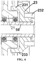
- FIG. 4 illustrates a section view of the core ring 23 according to one design.
- the core ring 23 in the prior art is a part or is integral; the core ring 23 comprises a body 231; and a periphery 233 of the body 231 is used for engaging the centrifugal mechanism 22, and more specifically, engaging the wheels 33 on the inner sides of each connecting rod 32 in the centrifugal mechanism 22.
- An inner ring of the body 231 of the core ring is rotatably sleeved on a fixed shaft 59, and a rear side thereof is provided with a concave part for accommodating a protruding portion of the guide wheel 21.
- the guide wheel 21 is mounted on the same fixed shaft 59 through a bearing.
- a front side of the core ring 23 is provided with a mounting feature 232, such as a mounting hole, for connecting parts associated with the safety activating module, so as to enable the safety activating module.
- FIG. 5 illustrates a core ring assembly 5 according to one embodiment of the present invention.
- the core ring assembly 5 for the governor of the elevator comprises: a first portion 51 and a second portion 52 of a core ring which are axially arranged, the first portion 51 and the second portion 52 of the core ring having contact surfaces S therebetween; and a pressure generation mechanism for generating a pressure between the first portion 51 and the second portion 52 of the core ring, e.g., a pressure in an axial direction, wherein the first portion 51 of the core ring rotates by receiving an actuation torque from, for example, an over-speed actuating mechanism of the governor, and the second portion 52 of the core ring rotates with the first portion 51 of the core ring by virtue of friction of the contact surfaces S and enables a safety activating module.
- the contact surfaces S between the first portion 51 and the second portion 52 of the core ring are conical surfaces. Taper angles of the conical surfaces may be freely adjusted depending on the size of a force expected to be output, e.g., the taper angles may be increased or decreased for the purpose of increasing or decreasing the friction to increase or decrease the force output.
- the contact surfaces S which are conical surfaces between the first portion 51 and the second portion 52 of the core ring fuller, there is a gap G between the first portion and the second portion at a position of outer rings of the contact surfaces which are conical surfaces between the first portion and the second portion of the core ring.
- the entire contact surfaces are conical surfaces without a gap, a situation that the contact between the inner rings of the contact surfaces between the first portion 51 and the second portion 52 of the core ring is not full may be caused due to machining tolerance of the outer rings of the contact surfaces.
- the gap G provided in the outer rings avoids this problem.
- the outer rings of the first portion 51 and the second portion 52 of the core ring are arranged to be flat surfaces perpendicular to an axial direction and oppositely disposed in parallel.
- the first portion 51 and the second portion 52 of the core ring rotate around the same axis A.
- the first portion 51 of the core ring has an opening for sleeving the fixed shaft 59 and is capable of rotating around the fixed shaft 59.
- the guide wheel 21 is also rotatably mounted on the fixed shaft 59 through a bearing. During normal operation, the guide wheel 21 rotates around the fixed shaft 59 while the core ring 23 is kept static until the centrifugal mechanism connected with the guide wheel 21 engages the outer ring of the first portion 51 of the core ring, thereby driving the first portion 51 of the core ring to rotate around the fixed shaft 59 and subsequently driving the second portion 52 of the core ring to rotate by virtue of friction.
- the first portion 51 of the core ring has a body 511, and a front side of the body 511 defines a surface 514 for frictional contact with the second portion 52 of the core ring.
- the front side of the body 511 of the first portion 51 of the core ring is formed as a convex conical surface or a concave conical surface.
- a rear side of the body 511 of the first portion 51 of the core ring is in a shape matching a guide wheel 21. In the specific embodiment illustrated in FIG.
- the rear side of the body 511 of the first portion 51 of the core ring defines a concave part 513 for accommodating a protruding portion of the guide wheel 21.
- the rear side of the body 511 of the first portion 51 of the core ring may also be provided as a flat surface perpendicular to an axial direction. In the specific embodiment illustrated in FIG.
- a cylindrical contraction part 512 extends from an inner ring on the front side of the body 511 of the first portion 51 of the core ring, and the second portion 52 of the core ring is sleeved on the cylindrical contraction part 512 of the first portion 51 of the core ring.
- the second portion 52 of the core ring has a body 520.
- a rear side of the body 520 of the second portion 52 of the core ring defines a surface matching the convex conical surface or the convex conical surface of the first portion of the core ring, the surface being illustrated as a concave conical surface 521 in the drawing.
- the second portion 52 of the core ring has a cylindrical extension part 522.
- the cylindrical extension part 522 is provided thereon with a feature such as a connecting part connected with parts associated with the safety activating module, e.g., a bolt hole 523 or other types of connecting features.
- a bearing such as a thrust bearing 55, is provided between the cylindrical contraction part 512 of the first portion 51 and the cylindrical extension part 522 of the second portion 52, such that the second portion 52 of the core ring can rotatably sleeve the cylindrical contraction part 512 of the first portion 51 of the core ring in a rolling manner.
- the pressure generation mechanism may also be provided between the cylindrical contraction part 512 of the first portion 51 of the core ring and the cylindrical extension part 522 of the second portion of the core ring.
- the pressure generation mechanism may comprise an elastic device 56, such as one or multiple disc springs.
- One end of the elastic device 56 acts on the inner side of the second portion of the core ring, and the other end of the elastic device acts on a stopper 54 on the cylindrical contraction part 512 of the first portion 51 of the core ring directly or by virtue of the thrust bearing 55.
- a thread is provided at a front end of the cylindrical contraction part 512, and the stopper 54 is a nut screwed onto the cylindrical contraction part 512.
- the pressure of the pressure generation mechanism may be adjusted by adjusting the tightness of the stopper 54, so as to adjust the pressure and friction force between the first portion and the second portion of the core ring.
- axial positioning of the entire core ring assembly may be realized through a clamping ring 57 provided on the shaft 59.
- the second portion 52 of the core ring assembly 5 is only subject to a substantially constant friction force from the first portion 51 of the core ring.
- the output of the friction force only depends on a friction coefficient and a pressure between the first portion and the second portion of the core ring.
- the output force may be adjusted by adjusting the tightness or number of the elastic devices such as disc springs.
- the sheave is still allowed to rotate, so as to avoid sliding friction between the rope and the sheave as well as the problem caused thereby.
- the first portion and the second portion of the governor can rotate relatively, excessive force will not be produced to output to the safety activating module at the moment of braking, and a greater impact will not be caused to the sheave or the rope due to a counteracting force, either.
- the tensile force exerted on the rope tends to be consistent or substantially consistent, such that the requirement on the rope does not change with the height of the building. Excessive impact is consumed due to the friction between the first portion and the second portion of the core ring.
- FIG. 5 illustrates a detailed structure of the core ring assembly according to the specific embodiment of the present invention, it should be understood that the present invention is not limited by this specific structure.
- the concept of the present invention is to transfer a suitable force output for actuating the safety activating module by virtue of the friction between at least two portions of the split-type core ring assembly while filtering out the excessive force output by virtue of friction simultaneously, so as to at least solve or relieve the above-mentioned problem or other problems existing in the prior art. Therefore, the scope of the present invention shall not be limited by the specific embodiments.
- the purpose of the present invention is further to provide various governors and elevator systems provided with the core ring assembly according to each embodiment of the present invention.
- the governor is preferably a car-mounted governor, and the second portion of the core ring assembly can be directly or indirectly connected to the safety activating module, such as a pulling rod of a security gear pulling mechanism.
Landscapes
- Engineering & Computer Science (AREA)
- Mechanical Engineering (AREA)
- General Engineering & Computer Science (AREA)
- Maintenance And Inspection Apparatuses For Elevators (AREA)
Claims (15)
- Aufzugsregler (18), der Folgendes umfasst:
eine Kernringbaugruppe (5), die Folgendes beinhaltet:einen ersten Abschnitt (51) und einen zweiten Abschnitt (52) eines Kernrings (23), die axial angeordnet sind, wobei der erste Abschnitt (51) und der zweite Abschnitt (52) des Kernrings (23) Kontaktflächen (S) zwischen diesen aufweisen; undeinen Druckerzeugungsmechanismus zum Erzeugen eines Drucks zwischen dem ersten Abschnitt (51) und dem zweiten Abschnitt (52) des Kernrings (23),wobei sich der erste Abschnitt (51) des Kernrings (23) dreht, indem er ein Betätigungsmoment von einem Überdrehzahl-Betätigungsmechanismus empfängt, und sich der zweite Abschnitt (52) des Kernrings (23) aufgrund von einer Reibung der Kontaktflächen (S) dreht und ein Sicherheitsaktivierungsmodul freigibt,dadurch gekennzeichnet, dass die Kontaktflächen (S) zwischen dem ersten Abschnitt (51) und dem zweiten Abschnitt (52) des Kernrings (23) konische Flächen sind. - Aufzugsregler (18) nach Anspruch 1, wobei es an äußeren Ringen der Kontaktflächen (S), die konische Flächen sind, zwischen dem ersten Abschnitt (51) und dem zweiten Abschnitt (52) des Kernrings (23) eine Lücke (G) gibt.
- Aufzugsregler (18) nach Anspruch 1 oder 2, wobei sich der erste Abschnitt (51) und der zweite Abschnitt (52) des Kernrings (23) um die gleiche Achse drehen.
- Aufzugsregler (18) nach Anspruch 1 bis 3, wobei der erste Abschnitt (51) des Kernrings (23) eine Öffnung zum Ummanteln einer festen Welle aufweist und um die feste Welle drehbar ist.
- Aufzugsregler (18) nach Anspruch 4, wobei darin der erste Abschnitt (51) des Kernrings (23) einen Körper aufweist und eine Vorderseite des Körpers des ersten Abschnitts (51) des Kernrings (23) eine Fläche für einen Reibungskontakt mit dem zweiten Abschnitt (52) des Kernrings (23) definiert.
- Aufzugsregler (18) nach Anspruch 5, wobei darin die Vorderseite des Körpers des ersten Abschnitts (51) des Kernrings (23) als eine konvexe konische Fläche gebildet ist; und/oder eine Rückseite des Körpers des ersten Abschnitts (51) des Kernrings (23) in einer Form ist, die zu einem Leitrad passt.
- Aufzugsregler (18) nach Anspruch 6, wobei sich ein zylindrisches Kontraktionsteil von einem inneren Ring an der Vorderseite des Körpers des ersten Abschnitts (51) des Kernrings (23) erstreckt und der zweite Abschnitt (52) des Kernrings (23) an dem zylindrischen Kontraktionsteil des ersten Abschnitts (51) des Kernrings (23) ummantelt ist.
- Aufzugsregler (18) nach Anspruch 7, wobei ein Lager zwischen dem zweiten Abschnitt (52) des Kernrings (23) und dem zylindrischen Kontraktionsteil des ersten Abschnitts (51) des Kernrings (23) bereitgestellt ist;
wobei insbesondere der zweite Abschnitt (52) des Kernrings (23) einen Körper aufweist und eine Rückseite des Körpers des zweiten Abschnitts (52) des Kernrings (23) eine konkave konische Fläche definiert, die zu der konvexen konischen Fläche des ersten Abschnitts (51) des Kernrings (23) passt. - Aufzugsregler (18) nach Anspruch 7 oder 8, wobei der zweite Abschnitt (52) des Kernrings (23) einen zylindrischen Verlängerungsteil aufweist und der zylindrische Verlängerungsteil daran mit einem Verbindungsteil bereitgestellt ist, das mit dem Sicherheitsaktivierungsmodul verbunden ist;
wobei insbesondere der Druckerzeugungsmechanismus zwischen dem zylindrischen Kontraktionsteil des ersten Abschnitts (51) des Kernrings (23) und dem zylindrischen Verlängerungsteil des zweiten Abschnitts (52) des Kernrings (23) angeordnet ist. - Aufzugsregler (18) nach Anspruch 9, wobei der Druckerzeugungsmechanismus eine elastische Vorrichtung mit einem Ende, das auf eine innere Seite des zweiten Abschnitts (52) des Kernrings (23) wirkt, und dem anderen Ende umfasst, das auf einen Anschlag an dem zylindrischen Kontraktionsteil des ersten Abschnitts (51) des Kernrings (23) wirkt.
- Aufzugsregler (18) nach Anspruch 10, wobei ein Axiallager zwischen der elastischen Vorrichtung und dem Anschlag an dem zylindrischen Kontraktionsteil des ersten Abschnitts (51) des Kernrings (23) bereitgestellt ist;
und/oder
wobei die elastische Vorrichtung eine oder mehrere Tellerfedern ist. - Aufzugsregler (18) nach Anspruch 10 oder 11, wobei ein Gewinde an dem zylindrischen Kontraktionsteil bereitgestellt ist und der Anschlag eine Mutter ist, die an das zylindrische Kontraktionsteil geschraubt ist.
- Aufzugsregler (18) nach einem der Ansprüche 1 bis 12, der ein kabinenmontierter Regler ist.
- Aufzugsregler (18) nach einem der Ansprüche 1 bis 13, wobei der zweite Abschnitt (52) des Kernrings (23) mit einer Zugstange für eine Aufzugssicherheitseinrichtung verbunden ist.
- Aufzugssystem, das den Aufzugsregler (18) nach einem der vorhergehenden Ansprüche umfasst.
Applications Claiming Priority (1)
| Application Number | Priority Date | Filing Date | Title |
|---|---|---|---|
| CN201710024109.2A CN108298398B (zh) | 2017-01-13 | 2017-01-13 | 用于电梯限速器的芯环组件,限速器和电梯系统 |
Publications (2)
| Publication Number | Publication Date |
|---|---|
| EP3360834A1 EP3360834A1 (de) | 2018-08-15 |
| EP3360834B1 true EP3360834B1 (de) | 2021-03-03 |
Family
ID=60957211
Family Applications (1)
| Application Number | Title | Priority Date | Filing Date |
|---|---|---|---|
| EP18151412.6A Active EP3360834B1 (de) | 2017-01-13 | 2018-01-12 | Ringbaugruppe für aufzugsregler, regler und aufzugssystem |
Country Status (3)
| Country | Link |
|---|---|
| US (1) | US11078044B2 (de) |
| EP (1) | EP3360834B1 (de) |
| CN (1) | CN108298398B (de) |
Families Citing this family (5)
| Publication number | Priority date | Publication date | Assignee | Title |
|---|---|---|---|---|
| GB2527295A (en) * | 2014-06-16 | 2015-12-23 | Stannah Stairlifts Ltd | Improvements in or relating to stairlifts |
| CN109720961B (zh) * | 2017-10-30 | 2021-08-17 | 奥的斯电梯公司 | 限速器组件以及电梯系统 |
| US20220112927A1 (en) * | 2019-10-25 | 2022-04-14 | Mcintosh Brake Systems, Llc | Brake system and method |
| CN115611111B (zh) * | 2021-07-13 | 2025-07-22 | 杭州沪宁电梯部件股份有限公司 | 一种限速器提拉力调整装置 |
| US20260109574A1 (en) * | 2024-10-22 | 2026-04-23 | Otis Elevator Company | Electromechanical safety actuation of elevator governors |
Family Cites Families (26)
| Publication number | Priority date | Publication date | Assignee | Title |
|---|---|---|---|---|
| US3695399A (en) | 1970-10-26 | 1972-10-03 | Marvin R Laing | Overspeed safety brake for elevators |
| US3741527A (en) * | 1971-10-12 | 1973-06-26 | Eaton Corp | Stress limiting hoist |
| US3966027A (en) | 1975-04-04 | 1976-06-29 | Humphrey Elevator And Truck Company | Braking apparatus for stopping a rotating shaft |
| FR2341513A1 (fr) * | 1976-02-23 | 1977-09-16 | David Pierre | Dispositif de freinage de securite pour equipage mobile le long d'une surface, notamment pour cabine d'ascenseur |
| DE2744908C2 (de) * | 1977-10-06 | 1984-02-02 | Ringspann Albrecht Maurer Kg, 6380 Bad Homburg | Überlastkupplung |
| DE2818600C3 (de) * | 1978-04-27 | 1981-02-05 | Soell Kg Industrieschmiede, 8670 Hof | Fangbremse mit Geschwindigkeitsbegrenzer |
| DE2931732C2 (de) | 1979-08-04 | 1983-01-27 | Deere & Co., Moline, Ill., US, Niederlassung Deere & Co. European Office, 6800 Mannheim | Rutschkupplung |
| US4856623A (en) | 1982-12-06 | 1989-08-15 | Romig Jr Byron A | Overspeed brake |
| US5007505A (en) | 1990-03-19 | 1991-04-16 | Northern Elevator Limited | Elevator traction sheave brake |
| US5201821A (en) | 1992-01-08 | 1993-04-13 | Otis Elevator Company | Disc brake elevator drive sheave |
| FI92996C (fi) | 1993-09-20 | 1995-02-10 | Scaninter Nokia Ltd Oy | Jarrusovitelma |
| FI94949C (fi) | 1994-01-05 | 1995-11-27 | Kone Oy | Menetelmä ja laitteisto hissin tarrauslaitteen laukaisemiseksi |
| DE19536995C2 (de) * | 1995-10-04 | 2000-11-16 | Wittur Aufzugteile Gmbh & Co | Sicherheitsbremse für seilbetriebene Förderanlagen |
| KR20040101561A (ko) | 2003-02-27 | 2004-12-02 | 미쓰비시덴키 가부시키가이샤 | 엘리베이터용 권상기 |
| JP4764657B2 (ja) * | 2005-04-28 | 2011-09-07 | 株式会社日立製作所 | エレベーター用調速機 |
| CN2934166Y (zh) | 2006-05-29 | 2007-08-15 | 义乌市双林起重设备安装工程有限公司 | 限速器 |
| US8118143B2 (en) * | 2007-11-29 | 2012-02-21 | Axel Brandt | Centrifugal emergency brake |
| WO2009130366A1 (en) | 2008-04-23 | 2009-10-29 | Kone Corporation | Overspeed governor of an elevator, and elevator |
| CN201211987Y (zh) * | 2008-05-06 | 2009-03-25 | 河北东方富达机械有限公司 | 电梯遥控限速器 |
| EP2368058B1 (de) | 2008-11-24 | 2015-01-07 | Schaeffler Technologies GmbH & Co. KG | Anlasserscheibe mit rutschkupplung |
| FI122262B (fi) * | 2009-10-21 | 2011-11-15 | Kone Corp | Hissin liikkeenrajoitin ja hissi |
| ES2381966T3 (es) | 2009-11-10 | 2012-06-04 | Thyssenkrupp Elevator Ag | Dispositivo de liberación para un limitador de velocidad de una instalación de ascensor |
| EP2571799B1 (de) * | 2010-05-18 | 2021-03-17 | Otis Elevator Company | Integriertes sicherheitssystem für einen aufzug |
| EP2855325B1 (de) | 2012-05-31 | 2021-08-25 | Otis Elevator Company | Betätigungsvorrichtung für einen fahrzeugmontierten überdrehzahlregler |
| CN105565104B (zh) * | 2015-12-22 | 2019-07-23 | 杭州康特尔电梯部件有限公司 | 电梯限速器 |
| CN105502126B (zh) | 2016-01-28 | 2017-10-10 | 浙江屹立电梯有限公司 | 离合式电梯限速器 |
-
2017
- 2017-01-13 CN CN201710024109.2A patent/CN108298398B/zh active Active
-
2018
- 2018-01-11 US US15/868,617 patent/US11078044B2/en active Active
- 2018-01-12 EP EP18151412.6A patent/EP3360834B1/de active Active
Non-Patent Citations (1)
| Title |
|---|
| None * |
Also Published As
| Publication number | Publication date |
|---|---|
| US20180201480A1 (en) | 2018-07-19 |
| EP3360834A1 (de) | 2018-08-15 |
| CN108298398B (zh) | 2020-09-01 |
| US11078044B2 (en) | 2021-08-03 |
| CN108298398A (zh) | 2018-07-20 |
Similar Documents
| Publication | Publication Date | Title |
|---|---|---|
| US11078044B2 (en) | Ring assembly for elevator governor, governor and elevator system | |
| EP2673232B1 (de) | Aufzugsregler mit zwei auslösungsmechanismen auf separaten scheiben | |
| US6223868B1 (en) | Brake mechanism for device for hauling up/down by rope | |
| WO2010023745A1 (ja) | エレベータ用調速機 | |
| US4257494A (en) | Safety brake for elevators and aerial cableways | |
| EP3326952B1 (de) | Fernauslösevorrichtung, überdrehzahlregleranordnung und aufzug | |
| CN106744414A (zh) | 具有机械式防坠功能的舞台吊杆卷扬机 | |
| JPH0525800B2 (de) | ||
| EP3560875B1 (de) | Geschwindigkeitsbegrenzer und aufzugssystem | |
| CN204823557U (zh) | 限速器 | |
| JP5845317B2 (ja) | エレベータの調速機 | |
| SE542512C2 (sv) | Säkerhetsbroms vid hiss | |
| EP2957788A1 (de) | Zum Schwebeflug fähiges Luftfahrzeug mit Drehmomentbegrenzer | |
| EP2490971B1 (de) | Steuergerät fur unbeabsichtigte bewegung und aufzug | |
| JP2016108143A (ja) | エレベータ用調速装置 | |
| CN112573319B (zh) | 一种绳轮机构及采用该绳轮机构的限速器 | |
| US20180251336A1 (en) | Elevator brake | |
| EP3630664B1 (de) | Anordnung in einem aufzug zum anhalten einer unkontrollierten bewegung der aufzugskabine | |
| CN105435381A (zh) | 一种自动控制匀速下降装置 | |
| CN216272556U (zh) | 电梯限速器 | |
| IT202100003905A1 (it) | Freno di emergenza | |
| KR101615148B1 (ko) | 추락방지기능을 구비한 셔터장치 | |
| CN110436296A (zh) | 一种曳引电梯紧急制动用限速器 | |
| KR200243892Y1 (ko) | 승강기용 브레이크장치 | |
| KR20210059085A (ko) | 가변형 로프드럼이 구비된 동력등강기 |
Legal Events
| Date | Code | Title | Description |
|---|---|---|---|
| PUAI | Public reference made under article 153(3) epc to a published international application that has entered the european phase |
Free format text: ORIGINAL CODE: 0009012 |
|
| STAA | Information on the status of an ep patent application or granted ep patent |
Free format text: STATUS: THE APPLICATION HAS BEEN PUBLISHED |
|
| AK | Designated contracting states |
Kind code of ref document: A1 Designated state(s): AL AT BE BG CH CY CZ DE DK EE ES FI FR GB GR HR HU IE IS IT LI LT LU LV MC MK MT NL NO PL PT RO RS SE SI SK SM TR |
|
| AX | Request for extension of the european patent |
Extension state: BA ME |
|
| RIN1 | Information on inventor provided before grant (corrected) |
Inventor name: SHI, ZHENGBAO |
|
| STAA | Information on the status of an ep patent application or granted ep patent |
Free format text: STATUS: REQUEST FOR EXAMINATION WAS MADE |
|
| 17P | Request for examination filed |
Effective date: 20190131 |
|
| RBV | Designated contracting states (corrected) |
Designated state(s): AL AT BE BG CH CY CZ DE DK EE ES FI FR GB GR HR HU IE IS IT LI LT LU LV MC MK MT NL NO PL PT RO RS SE SI SK SM TR |
|
| GRAP | Despatch of communication of intention to grant a patent |
Free format text: ORIGINAL CODE: EPIDOSNIGR1 |
|
| STAA | Information on the status of an ep patent application or granted ep patent |
Free format text: STATUS: GRANT OF PATENT IS INTENDED |
|
| INTG | Intention to grant announced |
Effective date: 20200908 |
|
| GRAS | Grant fee paid |
Free format text: ORIGINAL CODE: EPIDOSNIGR3 |
|
| GRAA | (expected) grant |
Free format text: ORIGINAL CODE: 0009210 |
|
| STAA | Information on the status of an ep patent application or granted ep patent |
Free format text: STATUS: THE PATENT HAS BEEN GRANTED |
|
| AK | Designated contracting states |
Kind code of ref document: B1 Designated state(s): AL AT BE BG CH CY CZ DE DK EE ES FI FR GB GR HR HU IE IS IT LI LT LU LV MC MK MT NL NO PL PT RO RS SE SI SK SM TR |
|
| REG | Reference to a national code |
Ref country code: GB Ref legal event code: FG4D |
|
| REG | Reference to a national code |
Ref country code: AT Ref legal event code: REF Ref document number: 1367002 Country of ref document: AT Kind code of ref document: T Effective date: 20210315 Ref country code: CH Ref legal event code: EP |
|
| REG | Reference to a national code |
Ref country code: DE Ref legal event code: R096 Ref document number: 602018013203 Country of ref document: DE |
|
| REG | Reference to a national code |
Ref country code: IE Ref legal event code: FG4D |
|
| REG | Reference to a national code |
Ref country code: LT Ref legal event code: MG9D |
|
| PG25 | Lapsed in a contracting state [announced via postgrant information from national office to epo] |
Ref country code: BG Free format text: LAPSE BECAUSE OF FAILURE TO SUBMIT A TRANSLATION OF THE DESCRIPTION OR TO PAY THE FEE WITHIN THE PRESCRIBED TIME-LIMIT Effective date: 20210603 Ref country code: LT Free format text: LAPSE BECAUSE OF FAILURE TO SUBMIT A TRANSLATION OF THE DESCRIPTION OR TO PAY THE FEE WITHIN THE PRESCRIBED TIME-LIMIT Effective date: 20210303 Ref country code: GR Free format text: LAPSE BECAUSE OF FAILURE TO SUBMIT A TRANSLATION OF THE DESCRIPTION OR TO PAY THE FEE WITHIN THE PRESCRIBED TIME-LIMIT Effective date: 20210604 Ref country code: HR Free format text: LAPSE BECAUSE OF FAILURE TO SUBMIT A TRANSLATION OF THE DESCRIPTION OR TO PAY THE FEE WITHIN THE PRESCRIBED TIME-LIMIT Effective date: 20210303 Ref country code: FI Free format text: LAPSE BECAUSE OF FAILURE TO SUBMIT A TRANSLATION OF THE DESCRIPTION OR TO PAY THE FEE WITHIN THE PRESCRIBED TIME-LIMIT Effective date: 20210303 Ref country code: NO Free format text: LAPSE BECAUSE OF FAILURE TO SUBMIT A TRANSLATION OF THE DESCRIPTION OR TO PAY THE FEE WITHIN THE PRESCRIBED TIME-LIMIT Effective date: 20210603 |
|
| REG | Reference to a national code |
Ref country code: NL Ref legal event code: MP Effective date: 20210303 |
|
| REG | Reference to a national code |
Ref country code: AT Ref legal event code: MK05 Ref document number: 1367002 Country of ref document: AT Kind code of ref document: T Effective date: 20210303 |
|
| PG25 | Lapsed in a contracting state [announced via postgrant information from national office to epo] |
Ref country code: SE Free format text: LAPSE BECAUSE OF FAILURE TO SUBMIT A TRANSLATION OF THE DESCRIPTION OR TO PAY THE FEE WITHIN THE PRESCRIBED TIME-LIMIT Effective date: 20210303 Ref country code: RS Free format text: LAPSE BECAUSE OF FAILURE TO SUBMIT A TRANSLATION OF THE DESCRIPTION OR TO PAY THE FEE WITHIN THE PRESCRIBED TIME-LIMIT Effective date: 20210303 Ref country code: PL Free format text: LAPSE BECAUSE OF FAILURE TO SUBMIT A TRANSLATION OF THE DESCRIPTION OR TO PAY THE FEE WITHIN THE PRESCRIBED TIME-LIMIT Effective date: 20210303 Ref country code: LV Free format text: LAPSE BECAUSE OF FAILURE TO SUBMIT A TRANSLATION OF THE DESCRIPTION OR TO PAY THE FEE WITHIN THE PRESCRIBED TIME-LIMIT Effective date: 20210303 |
|
| PG25 | Lapsed in a contracting state [announced via postgrant information from national office to epo] |
Ref country code: NL Free format text: LAPSE BECAUSE OF FAILURE TO SUBMIT A TRANSLATION OF THE DESCRIPTION OR TO PAY THE FEE WITHIN THE PRESCRIBED TIME-LIMIT Effective date: 20210303 |
|
| PG25 | Lapsed in a contracting state [announced via postgrant information from national office to epo] |
Ref country code: CZ Free format text: LAPSE BECAUSE OF FAILURE TO SUBMIT A TRANSLATION OF THE DESCRIPTION OR TO PAY THE FEE WITHIN THE PRESCRIBED TIME-LIMIT Effective date: 20210303 Ref country code: EE Free format text: LAPSE BECAUSE OF FAILURE TO SUBMIT A TRANSLATION OF THE DESCRIPTION OR TO PAY THE FEE WITHIN THE PRESCRIBED TIME-LIMIT Effective date: 20210303 Ref country code: SM Free format text: LAPSE BECAUSE OF FAILURE TO SUBMIT A TRANSLATION OF THE DESCRIPTION OR TO PAY THE FEE WITHIN THE PRESCRIBED TIME-LIMIT Effective date: 20210303 Ref country code: AT Free format text: LAPSE BECAUSE OF FAILURE TO SUBMIT A TRANSLATION OF THE DESCRIPTION OR TO PAY THE FEE WITHIN THE PRESCRIBED TIME-LIMIT Effective date: 20210303 |
|
| PG25 | Lapsed in a contracting state [announced via postgrant information from national office to epo] |
Ref country code: IS Free format text: LAPSE BECAUSE OF FAILURE TO SUBMIT A TRANSLATION OF THE DESCRIPTION OR TO PAY THE FEE WITHIN THE PRESCRIBED TIME-LIMIT Effective date: 20210703 Ref country code: PT Free format text: LAPSE BECAUSE OF FAILURE TO SUBMIT A TRANSLATION OF THE DESCRIPTION OR TO PAY THE FEE WITHIN THE PRESCRIBED TIME-LIMIT Effective date: 20210705 Ref country code: RO Free format text: LAPSE BECAUSE OF FAILURE TO SUBMIT A TRANSLATION OF THE DESCRIPTION OR TO PAY THE FEE WITHIN THE PRESCRIBED TIME-LIMIT Effective date: 20210303 Ref country code: SK Free format text: LAPSE BECAUSE OF FAILURE TO SUBMIT A TRANSLATION OF THE DESCRIPTION OR TO PAY THE FEE WITHIN THE PRESCRIBED TIME-LIMIT Effective date: 20210303 |
|
| REG | Reference to a national code |
Ref country code: DE Ref legal event code: R097 Ref document number: 602018013203 Country of ref document: DE |
|
| PLBE | No opposition filed within time limit |
Free format text: ORIGINAL CODE: 0009261 |
|
| STAA | Information on the status of an ep patent application or granted ep patent |
Free format text: STATUS: NO OPPOSITION FILED WITHIN TIME LIMIT |
|
| PG25 | Lapsed in a contracting state [announced via postgrant information from national office to epo] |
Ref country code: AL Free format text: LAPSE BECAUSE OF FAILURE TO SUBMIT A TRANSLATION OF THE DESCRIPTION OR TO PAY THE FEE WITHIN THE PRESCRIBED TIME-LIMIT Effective date: 20210303 Ref country code: DK Free format text: LAPSE BECAUSE OF FAILURE TO SUBMIT A TRANSLATION OF THE DESCRIPTION OR TO PAY THE FEE WITHIN THE PRESCRIBED TIME-LIMIT Effective date: 20210303 Ref country code: ES Free format text: LAPSE BECAUSE OF FAILURE TO SUBMIT A TRANSLATION OF THE DESCRIPTION OR TO PAY THE FEE WITHIN THE PRESCRIBED TIME-LIMIT Effective date: 20210303 |
|
| 26N | No opposition filed |
Effective date: 20211206 |
|
| PG25 | Lapsed in a contracting state [announced via postgrant information from national office to epo] |
Ref country code: SI Free format text: LAPSE BECAUSE OF FAILURE TO SUBMIT A TRANSLATION OF THE DESCRIPTION OR TO PAY THE FEE WITHIN THE PRESCRIBED TIME-LIMIT Effective date: 20210303 |
|
| PG25 | Lapsed in a contracting state [announced via postgrant information from national office to epo] |
Ref country code: IT Free format text: LAPSE BECAUSE OF FAILURE TO SUBMIT A TRANSLATION OF THE DESCRIPTION OR TO PAY THE FEE WITHIN THE PRESCRIBED TIME-LIMIT Effective date: 20210303 |
|
| PG25 | Lapsed in a contracting state [announced via postgrant information from national office to epo] |
Ref country code: IS Free format text: LAPSE BECAUSE OF FAILURE TO SUBMIT A TRANSLATION OF THE DESCRIPTION OR TO PAY THE FEE WITHIN THE PRESCRIBED TIME-LIMIT Effective date: 20210703 |
|
| PG25 | Lapsed in a contracting state [announced via postgrant information from national office to epo] |
Ref country code: MC Free format text: LAPSE BECAUSE OF FAILURE TO SUBMIT A TRANSLATION OF THE DESCRIPTION OR TO PAY THE FEE WITHIN THE PRESCRIBED TIME-LIMIT Effective date: 20210303 |
|
| REG | Reference to a national code |
Ref country code: CH Ref legal event code: PL |
|
| GBPC | Gb: european patent ceased through non-payment of renewal fee |
Effective date: 20220112 |
|
| REG | Reference to a national code |
Ref country code: BE Ref legal event code: MM Effective date: 20220131 |
|
| PG25 | Lapsed in a contracting state [announced via postgrant information from national office to epo] |
Ref country code: LU Free format text: LAPSE BECAUSE OF NON-PAYMENT OF DUE FEES Effective date: 20220112 Ref country code: GB Free format text: LAPSE BECAUSE OF NON-PAYMENT OF DUE FEES Effective date: 20220112 |
|
| PG25 | Lapsed in a contracting state [announced via postgrant information from national office to epo] |
Ref country code: BE Free format text: LAPSE BECAUSE OF NON-PAYMENT OF DUE FEES Effective date: 20220131 |
|
| PG25 | Lapsed in a contracting state [announced via postgrant information from national office to epo] |
Ref country code: LI Free format text: LAPSE BECAUSE OF NON-PAYMENT OF DUE FEES Effective date: 20220131 Ref country code: CH Free format text: LAPSE BECAUSE OF NON-PAYMENT OF DUE FEES Effective date: 20220131 |
|
| PG25 | Lapsed in a contracting state [announced via postgrant information from national office to epo] |
Ref country code: IE Free format text: LAPSE BECAUSE OF NON-PAYMENT OF DUE FEES Effective date: 20220112 |
|
| PG25 | Lapsed in a contracting state [announced via postgrant information from national office to epo] |
Ref country code: HU Free format text: LAPSE BECAUSE OF FAILURE TO SUBMIT A TRANSLATION OF THE DESCRIPTION OR TO PAY THE FEE WITHIN THE PRESCRIBED TIME-LIMIT; INVALID AB INITIO Effective date: 20180112 |
|
| PG25 | Lapsed in a contracting state [announced via postgrant information from national office to epo] |
Ref country code: MK Free format text: LAPSE BECAUSE OF FAILURE TO SUBMIT A TRANSLATION OF THE DESCRIPTION OR TO PAY THE FEE WITHIN THE PRESCRIBED TIME-LIMIT Effective date: 20210303 Ref country code: CY Free format text: LAPSE BECAUSE OF FAILURE TO SUBMIT A TRANSLATION OF THE DESCRIPTION OR TO PAY THE FEE WITHIN THE PRESCRIBED TIME-LIMIT Effective date: 20210303 |
|
| PG25 | Lapsed in a contracting state [announced via postgrant information from national office to epo] |
Ref country code: MT Free format text: LAPSE BECAUSE OF FAILURE TO SUBMIT A TRANSLATION OF THE DESCRIPTION OR TO PAY THE FEE WITHIN THE PRESCRIBED TIME-LIMIT Effective date: 20210303 |
|
| PG25 | Lapsed in a contracting state [announced via postgrant information from national office to epo] |
Ref country code: TR Free format text: LAPSE BECAUSE OF FAILURE TO SUBMIT A TRANSLATION OF THE DESCRIPTION OR TO PAY THE FEE WITHIN THE PRESCRIBED TIME-LIMIT Effective date: 20210303 |
|
| PGFP | Annual fee paid to national office [announced via postgrant information from national office to epo] |
Ref country code: FR Payment date: 20251217 Year of fee payment: 9 |
|
| PGFP | Annual fee paid to national office [announced via postgrant information from national office to epo] |
Ref country code: DE Payment date: 20251217 Year of fee payment: 9 |