EP3361107A1 - Gelenkkörper, flüssigkeitsdruckzylinder und verfahren zur herstellung eines gelenkkörpers - Google Patents
Gelenkkörper, flüssigkeitsdruckzylinder und verfahren zur herstellung eines gelenkkörpers Download PDFInfo
- Publication number
- EP3361107A1 EP3361107A1 EP16853430.3A EP16853430A EP3361107A1 EP 3361107 A1 EP3361107 A1 EP 3361107A1 EP 16853430 A EP16853430 A EP 16853430A EP 3361107 A1 EP3361107 A1 EP 3361107A1
- Authority
- EP
- European Patent Office
- Prior art keywords
- peripheral surface
- contact
- protrusion
- cylinder
- outer peripheral
- Prior art date
- Legal status (The legal status is an assumption and is not a legal conclusion. Google has not performed a legal analysis and makes no representation as to the accuracy of the status listed.)
- Withdrawn
Links
Images


Classifications
-
- F—MECHANICAL ENGINEERING; LIGHTING; HEATING; WEAPONS; BLASTING
- F15—FLUID-PRESSURE ACTUATORS; HYDRAULICS OR PNEUMATICS IN GENERAL
- F15B—SYSTEMS ACTING BY MEANS OF FLUIDS IN GENERAL; FLUID-PRESSURE ACTUATORS, e.g. SERVOMOTORS; DETAILS OF FLUID-PRESSURE SYSTEMS, NOT OTHERWISE PROVIDED FOR
- F15B15/00—Fluid-actuated devices for displacing a member from one position to another; Gearing associated therewith
- F15B15/08—Characterised by the construction of the motor unit
- F15B15/14—Characterised by the construction of the motor unit of the straight-cylinder type
- F15B15/1423—Component parts; Constructional details
- F15B15/1438—Cylinder to end cap assemblies
-
- F—MECHANICAL ENGINEERING; LIGHTING; HEATING; WEAPONS; BLASTING
- F16—ENGINEERING ELEMENTS AND UNITS; GENERAL MEASURES FOR PRODUCING AND MAINTAINING EFFECTIVE FUNCTIONING OF MACHINES OR INSTALLATIONS; THERMAL INSULATION IN GENERAL
- F16B—DEVICES FOR FASTENING OR SECURING CONSTRUCTIONAL ELEMENTS OR MACHINE PARTS TOGETHER, e.g. NAILS, BOLTS, CIRCLIPS, CLAMPS, CLIPS OR WEDGES; JOINTS OR JOINTING
- F16B4/00—Shrinkage connections, e.g. assembled with the parts at different temperature; Force fits; Non-releasable friction-grip fastenings
- F16B4/004—Press fits, force fits, interference fits, i.e. fits without heat or chemical treatment
-
- B—PERFORMING OPERATIONS; TRANSPORTING
- B23—MACHINE TOOLS; METAL-WORKING NOT OTHERWISE PROVIDED FOR
- B23K—SOLDERING OR UNSOLDERING; WELDING; CLADDING OR PLATING BY SOLDERING OR WELDING; CUTTING BY APPLYING HEAT LOCALLY, e.g. FLAME CUTTING; WORKING BY LASER BEAM
- B23K20/00—Non-electric welding by applying impact or other pressure, with or without the application of heat, e.g. cladding or plating
- B23K20/12—Non-electric welding by applying impact or other pressure, with or without the application of heat, e.g. cladding or plating the heat being generated by friction; Friction welding
-
- B—PERFORMING OPERATIONS; TRANSPORTING
- B23—MACHINE TOOLS; METAL-WORKING NOT OTHERWISE PROVIDED FOR
- B23K—SOLDERING OR UNSOLDERING; WELDING; CLADDING OR PLATING BY SOLDERING OR WELDING; CUTTING BY APPLYING HEAT LOCALLY, e.g. FLAME CUTTING; WORKING BY LASER BEAM
- B23K20/00—Non-electric welding by applying impact or other pressure, with or without the application of heat, e.g. cladding or plating
- B23K20/12—Non-electric welding by applying impact or other pressure, with or without the application of heat, e.g. cladding or plating the heat being generated by friction; Friction welding
- B23K20/129—Non-electric welding by applying impact or other pressure, with or without the application of heat, e.g. cladding or plating the heat being generated by friction; Friction welding specially adapted for particular articles or work
-
- F—MECHANICAL ENGINEERING; LIGHTING; HEATING; WEAPONS; BLASTING
- F15—FLUID-PRESSURE ACTUATORS; HYDRAULICS OR PNEUMATICS IN GENERAL
- F15B—SYSTEMS ACTING BY MEANS OF FLUIDS IN GENERAL; FLUID-PRESSURE ACTUATORS, e.g. SERVOMOTORS; DETAILS OF FLUID-PRESSURE SYSTEMS, NOT OTHERWISE PROVIDED FOR
- F15B15/00—Fluid-actuated devices for displacing a member from one position to another; Gearing associated therewith
- F15B15/08—Characterised by the construction of the motor unit
- F15B15/14—Characterised by the construction of the motor unit of the straight-cylinder type
-
- F—MECHANICAL ENGINEERING; LIGHTING; HEATING; WEAPONS; BLASTING
- F16—ENGINEERING ELEMENTS AND UNITS; GENERAL MEASURES FOR PRODUCING AND MAINTAINING EFFECTIVE FUNCTIONING OF MACHINES OR INSTALLATIONS; THERMAL INSULATION IN GENERAL
- F16B—DEVICES FOR FASTENING OR SECURING CONSTRUCTIONAL ELEMENTS OR MACHINE PARTS TOGETHER, e.g. NAILS, BOLTS, CIRCLIPS, CLAMPS, CLIPS OR WEDGES; JOINTS OR JOINTING
- F16B11/00—Connecting constructional elements or machine parts by sticking or pressing them together, e.g. cold pressure welding
-
- F—MECHANICAL ENGINEERING; LIGHTING; HEATING; WEAPONS; BLASTING
- F16—ENGINEERING ELEMENTS AND UNITS; GENERAL MEASURES FOR PRODUCING AND MAINTAINING EFFECTIVE FUNCTIONING OF MACHINES OR INSTALLATIONS; THERMAL INSULATION IN GENERAL
- F16B—DEVICES FOR FASTENING OR SECURING CONSTRUCTIONAL ELEMENTS OR MACHINE PARTS TOGETHER, e.g. NAILS, BOLTS, CIRCLIPS, CLAMPS, CLIPS OR WEDGES; JOINTS OR JOINTING
- F16B11/00—Connecting constructional elements or machine parts by sticking or pressing them together, e.g. cold pressure welding
- F16B11/002—Connecting constructional elements or machine parts by sticking or pressing them together, e.g. cold pressure welding by pressing the elements together so as to obtain plastic deformation
-
- F—MECHANICAL ENGINEERING; LIGHTING; HEATING; WEAPONS; BLASTING
- F16—ENGINEERING ELEMENTS AND UNITS; GENERAL MEASURES FOR PRODUCING AND MAINTAINING EFFECTIVE FUNCTIONING OF MACHINES OR INSTALLATIONS; THERMAL INSULATION IN GENERAL
- F16B—DEVICES FOR FASTENING OR SECURING CONSTRUCTIONAL ELEMENTS OR MACHINE PARTS TOGETHER, e.g. NAILS, BOLTS, CIRCLIPS, CLAMPS, CLIPS OR WEDGES; JOINTS OR JOINTING
- F16B4/00—Shrinkage connections, e.g. assembled with the parts at different temperature; Force fits; Non-releasable friction-grip fastenings
Definitions
- the present invention relates to a bonded body, a fluid pressure cylinder including this bonded body, and a manufacturing method of this bonded body.
- JP2007-229719A discloses a method of bonding a cover body to an end portion of a tubular body by frictional pressure-contact and of sealing the end portion of the tubular body.
- the cover body used in this method is provided with an annular projection that abuts against the end surface of the tubular body, a boss portion formed on an inner side of the annular projection, and a flange portion formed at a distal end of the boss portion.
- outer diameters of the boss portion and the flange portion are smaller than an inner diameter of a tubular body, and a gap is formed between outer peripheral surfaces of the boss portion and the flange portion and an inner peripheral surface of the tubular body.
- the present invention has an object to prevent a shift between a first member and a second member during bonding.
- the present invention relates to a bonded body formed by frictional pressure-contact.
- the bonded body includes a first member including an end surface and a hollow portion with an opening in the end surface, and a second member including a body portion bonded to the end surface and a protrusion portion protruding from the body portion, the protrusion portion being accommodated in the hollow portion, wherein at least one of an inner peripheral surface of the hollow portion and an outer peripheral surface of the protrusion portion includes an inclined portion inclined to a radial direction of the opening, while the other is in contact with the inclined portion.
- the present invention relates to a manufacturing method of a bonded body formed by bonding a first member and a second member by frictional pressure-contact, the first member having a hollow portion with an opening in an end surface, the second member having a protrusion portion protruding from a body portion.
- the manufacturing method includes inserting the protrusion portion into the hollow portion and causing the body portion of the second member to abut against the end surface of the first member, relatively rotating the first member and the second member to generate heat on the end surface and the body portion, and pressing the first member and the second member to each other until an inclined portion formed on at least one of an inner peripheral surface of the hollow portion and an outer peripheral surface of the protrusion portion is brought into contact with the other, the inclined portion being inclined to a radial direction of the opening.
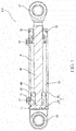
- the hydraulic cylinder 100 is used as an actuator mounted on a machine such as a construction machine and an industrial machine.
- the hydraulic cylinder 100 is used as an arm cylinder mounted on a hydraulic excavator, for example.
- the hydraulic cylinder 100 includes a bonded body 1 formed by bonding a cylinder tube (first member) 10 and a cylinder bottom (second member) 50 to each other by frictional pressure-contact.
- the cylinder tube 10 has a hollow portion 13 opened in both end surfaces 11 and 12, and one end surface 11 is closed by the cylinder bottom 50.
- the hydraulic cylinder 100 includes a piston 20 slidably accommodated in the hollow portion 13 of the cylinder tube 10 and a piston rod 30 inserted into the cylinder tube 10, capable of moving in/out.
- One end of the piston rod 30 is connected to the piston 20, while the other end of the piston rod 30 is extended from the cylinder tube 10 through the opening in the other end surface 12 of the cylinder tube 10.
- the opening in the other end surface 12 of the cylinder tube 10 is closed by the cylinder head 40.
- the cylinder head 40 is formed annularly and slidably supports the piston rod 30.
- the hydraulic cylinder 100 is mounted on a machine such as a construction machine and an industrial machine by using a connecting portion 31 provided on the other end of the piston rod 30 and a connecting portion 51 provided on the cylinder bottom 50.
- the piston 20 divides an inside of the cylinder tube 10 into a rod side chamber 14 and an anti-rod side chamber 15.
- the rod side chamber 14 is defined by the cylinder tube 10, the piston 20, and the cylinder head 40
- the anti-rod side chamber 15 is defined by the cylinder tube 10, the piston 20, and the cylinder bottom 50.
- the cylinder tube 10 is provided with a head-side port 16 that communicates with the rod side chamber 14 and a bottom-side port 17 that communicates with the anti-rod side chamber 15.
- the head-side port 16 and the bottom-side port 17 are selectively connected to a hydraulic pump (not shown) or a tank (not shown) through a switching valve (not shown).
- a hydraulic pump not shown
- a tank not shown
- a switching valve not shown
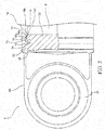
- Fig. 2 is a partial sectional view of a periphery of the cylinder bottom 50.
- an annular inclined portion 18 is formed on an inner peripheral surface of the hollow portion 13.
- the inclined portion 18 is inclined to the radial direction (the radial direction of the cylinder tube 10) of an opening of the hollow portion 13 so that an edge 18a on an outer side in the radial direction of the inclined portion 18 is located closer to the end surface 11 side than an edge 18b on an inner side in the radial direction.
- the inclined portion 18 may be formed having a tapered state (planar state) or may be formed having a curved shape.
- an inner burr 19a is formed on the cylinder tube 10 to protrude toward the inner side in the radial direction from an opening edge of the end surface 11.
- the inner burr 19a is formed by fluidity of a base metal of the cylinder tube 10.
- the cylinder bottom 50 has a body portion 52 bonded to the end surface 11 of the cylinder tube 10 and a protrusion portion 53 that protrudes from the body portion 52.
- the protrusion portion 53 is accommodated in the hollow portion 13 of the cylinder tube 10.
- An annular chamfered portion 54 as the inclined portion is formed on a distal end of an outer peripheral surface of the protrusion portion 53.
- the chamfered portion 54 is inclined to the radial direction of the opening of the hollow portion 13 (the radial direction of the cylinder tube 10) so that an edge 54a on the outer side in the radial direction of the chambered portion 54 is located closer to the body portion 52 side than an edge 54b on the inner side in the radial direction.
- the chamfered portion 54 may be formed having a tapered state (planar state) or may be formed having a curved shape.
- the inclined portion 18 of the cylinder tube 10 and the chamfered portion 54 of the cylinder bottom 50 are in contact with each other over the entire circumference. That is, a boundary of the anti-rod side chamber 15 is defined by a contact portion formed by contact between the inclined portion 18 and the chamfered portion 54 with each other.
- a dent 55 is formed on the outer peripheral surface of the protrusion portion 53.
- the dent 55 is located between the body portion 52 and the chamfered portion 54. More specifically, the dent 55 is formed so that its side surface continues from the end surface of the body portion 52 without a step.
- the end portion of the cylinder tube 10 which is pressed by the end surface of the body portion 52 in frictional pressure-contact and plastically fluidized, is guided as the inner burr 19a into the dent 55. Therefore, the inner burr 19a can be prevented from being sandwiched between the inclined portion 18 and the chamfered portion 54 during bonding, and the shift between the cylinder tube 10 and the cylinder bottom 50 can be prevented more reliably.
- An annular gap 56 is formed between the inner peripheral surface of the hollow portion 13 and the outer peripheral surface of the protrusion portion 53. Since the inclined portion 18 and the chamfered portion 54 are in contact with each other over the entire circumference, the gap 56 is formed as a sealed space. Therefore, a foreign substance in the gap 56 (oxidized scale generated on the surface of the inner burr 19a in frictional pressure-contact, for example) can be prevented from flowing out to the anti-rod side chamber 15.
- a manufacturing method of the hydraulic cylinder 100 will be described by referring to Figs. 3 to 6 .
- the manufacturing method of the bonded body 1 formed by bonding the cylinder tube 10 and the cylinder bottom 50 will be mainly described.
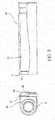
- Fig. 3 is a partial sectional view of the cylinder tube 10 and the cylinder bottom 50 before bonding
- Fig. 4 shows a periphery of one of the end surfaces of the cylinder tube shown in Fig. 3 in an enlarged manner.
- the base metal of the cylinder tube 10 has a cylindrical large-diameter portion 10a having the end surface 11 and a cylindrical small-diameter portion 10b having an inner diameter smaller than the inner diameter of the large-diameter portion 10a.
- the small-diameter portion 10b is provided continuously to the large-diameter portion 10a, and the inclined portion 18 is formed between the large-diameter portion 10a and the small-diameter portion 10b.
- an outer diameter R1 of the protrusion portion 53 is smaller than an inner diameter R2 of the large-diameter portion 10a and larger than the inner diameter of the small-diameter portion 10b.
- a dimension L1 from the body portion 52 to the chamfered portion 54 in the protrusion portion 53 is smaller than a dimension L2 from the end surface 11 to the inclined portion 18 in the large-diameter portion 10a.
- the protrusion portion 53 of the cylinder bottom 50 is inserted into the hollow portion 13 of the cylinder tube 10, and the body portion 52 of the cylinder bottom 50 is made to abut against the end surface 11 of the cylinder tube 10.
- a burr is generated on the body portion 52 and the large-diameter portion 10a by a heat generated on the contact portion between the body portion 52 and the large-diameter portion 10a.
- a gap is formed between the chamfered portion 54 and the inclined portion 18 in a state where the body portion 52 abuts against the end surface 11. Moreover, since the outer diameter R1 is smaller than the inner diameter R2, a gap is formed between the outer peripheral surface of the protrusion portion 53 and the inner peripheral surface of the large-diameter portion 10a.
- the gap is formed between the outer peripheral surface of the protrusion portion 53 and the inner peripheral surface of the large-diameter portion 10a, even if the cylinder tube 10 and the cylinder bottom 50 are relatively rotated, the friction heat is not generated on the outer peripheral surface of the protrusion portion 53 and the inner peripheral surface of the large-diameter portion 10a.
- the relative rotation of the cylinder tube 10 and the cylinder bottom 50 is stopped, and the cylinder tube 10 and the cylinder bottom 50 are pressed to each other until the inclined portion 18 of the cylinder tube 10 and the chamfered portion 54 are brought into contact with each other (see Fig. 6 ).
- a part of the large-diameter portion 10a of the cylinder tube 10 is pushed out to the inner side and the outer side of the cylinder tube 10. Therefore, the burr, which has been already formed on the large-diameter portion 10a, further grows (see the inner burr 19a and an outer burr 19b).
- the part of the body portion 52 of the cylinder bottom 50 is pushed out to the outer side. Therefore, the burr, which has been already formed on the body portion 52, further grows. (see the outer burr 52a).
- the inner burr 19a is guided to the dent 55 of the protrusion portion 53. Therefore, the inner burr 19a can be prevented from being sandwiched between the inclined portion 18 and the chamfered portion 54 when the cylinder tube 10 and the cylinder bottom 50 are pressed to each other.
- the inclined portion 18 and the chamfered portion 54 are formed with inclination to the radial direction of the opening of the hollow portion 13 (the radial direction of the cylinder tube 10).
- the cylinder bottom 50 is guided to the desired position in the radial direction with respect to the cylinder tube 10 by the contact between the inclined portion 18 and the chamfered portion 54. Therefore, a shift between the cylinder tube 10 and the cylinder bottom 50 can be prevented.
- the cylinder tube 10 and the cylinder bottom 50 are bonded by cooling the large-diameter portion 10a and the body portion 52. After that, by removing the outer burrs 19b and 52a by cutting or the like, the bonded body 1 is completed.
- the inner peripheral surface of the hollow portion 13 and the outer peripheral surface of the protrusion portion 53 have the inclined portion 18 and the chamfered portion 54 inclined to the radial direction, respectively, but this embodiment is not limited to that.
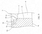
- Fig. 7 is a partial sectional view of the bonded body 1 according to another embodiment.
- the inclined portion 18 is formed on the inner peripheral surface of the cylinder tube 10, but a chamfered portion (inclined portion) 54 as shown in Fig. 2 is not formed on the outer peripheral surface of the protrusion portion 53.
- the cylinder bottom 50 is guided to the desired position in the radial direction with respect to the cylinder tube 10 by the contact between the inclined portion 18 and the outer peripheral surface of the protrusion portion 53 during bonding. Therefore, a shift between the cylinder tube 10 and the cylinder bottom 50 can be prevented.
- Fig. 8 is a partial sectional view of the bonded body 1 according to still another embodiment.
- the chamfered portion (inclined portion) 54 is formed on the outer peripheral surface of the protrusion portion 53, but on the inner peripheral surface of the cylinder tube 10, a stepped portion 18' is formed instead of the inclined portion 18 as shown in Fig. 2 .
- the cylinder bottom 50 is guided to the desired position in the radial direction with respect to the cylinder tube 10 by the contact between the stepped portion 18' and the chamfered portion 54 during bonding. Therefore, a shift between the cylinder tube 10 and the cylinder bottom 50 can be prevented.
- both the inner peripheral surface of the hollow portion 13 and the outer peripheral surface of the protrusion portion 53 have the inclined portion, the surface and the surface are brought into contact with each other.
- accuracy of centering is improved, and the shift between the cylinder tube 10 and the cylinder bottom 50 can be further prevented.
- the cylinder tube 10 or the cylinder bottom 50 can be formed easily.
- the bonded body 1 includes the first member 10 having the end surface 11 and the hollow portion 13 opened in the end surface 11 and the second member 50 having the body portion 52 bonded to the end surface 11 and the protrusion portion 53 protruding from the body portion 52, the protrusion portion 53 being accommodated in the hollow portion 13.
- the bonded body 1 is characterized that the inner peripheral surface of the hollow portion 13 has the inclined portion 18 inclined to the radial direction of the opening of the hollow portion 13, and the outer peripheral surface of the protrusion portion 53 is in contact with the inclined portion 18.
- the bonded body 1 is characterized that the outer peripheral surface of the protrusion portion 53 has the chamfered portion 54 inclined to the radial direction of the opening of the hollow portion 13, and the inner peripheral surface of the hollow portion 13 is in contact with the chamfered portion 54.
- the inner peripheral surface of the hollow portion 13 has the inclined portion 18, and the outer peripheral surface of the protrusion portion 53 is in contact with the inclined portion 18.
- the outer peripheral surface of the protrusion portion 53 has the chamfered portion 54, and the inner peripheral surface of the hollow portion 13 is in contact with the chamfered portion 54.
- the second member 50 further has the dent 55 on the outer peripheral surface of the protrusion portion 53, and the dent 55 is located between the contact portion between the inner peripheral surface of the hollow portion 13 and the outer peripheral surface of the protrusion portion 53 and the body portion 52.
- the dent 55 on the outer peripheral surface of the protrusion portion 53 is located between the body portion 52 and the contact portion, the inner burr 19a that is generated by plastic fluidity in the frictional pressure-contact is guided to the dent 55. Therefore, the inner burr 19a can be prevented from being sandwiched between the inclined portion 18 and the chamfered portion 54 during bonding, and the shift between the first member 10 and the second member 50 can be prevented more reliably.
- the bonded body 1 is characterized in that the inclined portion 18 is formed annularly, and the outer peripheral surface of the protrusion portion 53 is in contact with the inclined portion 18 over the entire circumference.
- the chamfered portion 54 is formed annularly, and the inner peripheral surface of the hollow portion 13 is in contact with the chamfered portion 54 over the entire circumference.
- the outer peripheral surface of the protrusion portion 53 is in contact with the inclined portion 18 over the entire circumference.
- the inner peripheral surface of the hollow portion 13 is in contact with the chamfered portion 54 over the entire circumference.
- the gap 56 between the body portion 52 and the contact portion is formed as a sealed space. Therefore, the foreign substance in the gap 56 can be prevented from flowing out to the anti-rod side chamber 15.
- the hydraulic cylinder 100 includes the aforementioned bonded body 1, the first member 10 is the cylinder tube 10, and the second member 50 is the cylinder bottom 50 closing the opening of the hollow portion 13.
- the first member 10 is the cylinder tube 10 and the second member 50 is the cylinder bottom 50 and thus, when the cylinder tube 10 and the cylinder bottom 50 are to be bonded together, the cylinder bottom 50 is guided to the desired position in the radial direction with respect to the cylinder tube 10. Therefore, a shift between the cylinder tube 10 and the cylinder bottom 50 during bonding can be prevented.
- this embodiment relates to the method of manufacturing the bonded body 1 formed by bonding the first member 10 having the hollow portion 13 opened in the end surface 11 and the second member 50 having the protrusion portion 53 protruding from the body portion 52 by frictional pressure-contact.
- the manufacturing method of the bonded body 1 includes a process of inserting the protrusion portion 53 into the hollow portion 13 and of causing the body portion 52 of the second member 50 to abut against the end surface 11 of the first member 10 and a process of relatively rotating the first member 10 and the second member 50 so as to generate heat on the end surface 11 and the body portion 52.
- This manufacturing method further includes a step of pressing the first member 10 and the second member 50 to each other until the inclined portion 18 formed on the inner peripheral surface of the hollow portion 13 and inclined to the radial direction of the opening of the hollow portion 13 is brought into contact with the outer peripheral surface of the protrusion portion 53 or a process of pressing the first member 10 and the second member 50 to each other until the chamfered portion 54 formed on the outer peripheral surface of the protrusion portion 53 and inclined to the radial direction of the opening of the hollow portion 13 is brought into contact with the inner peripheral surface of the hollow portion 13.
- the dent 55 does not have to be provided in the outer peripheral portion of the protrusion portion 53.
- the inner peripheral surface of the hollow portion 13 and the outer peripheral surface of the protrusion portion 53 may be brought into contact with each other by increasing the thickness of the small-diameter portion 10b so as to overlap the protrusion portion 53 of the cylinder bottom 50. Since the dent does not have to be made in the protrusion portion 53, a machining cost of the cylinder bottom 50 can be reduced.
- the inclined portion 18 and the chamfered portion 54 do not have to be in contact over the entire circumference. A part of the inclined portion 18 and a part of the chamfered portion 54 may be in contact. A part of the inclined portion 18 and a part of the chamfered portion 54 do not have to be formed annularly.
Landscapes
- Engineering & Computer Science (AREA)
- General Engineering & Computer Science (AREA)
- Mechanical Engineering (AREA)
- Physics & Mathematics (AREA)
- Fluid Mechanics (AREA)
- Pressure Welding/Diffusion-Bonding (AREA)
- Actuator (AREA)
- Standing Axle, Rod, Or Tube Structures Coupled By Welding, Adhesion, Or Deposition (AREA)
- Catching Or Destruction (AREA)
- Cylinder Crankcases Of Internal Combustion Engines (AREA)
Applications Claiming Priority (2)
| Application Number | Priority Date | Filing Date | Title |
|---|---|---|---|
| JP2015197869A JP6611544B2 (ja) | 2015-10-05 | 2015-10-05 | 接合体、流体圧シリンダ、及び接合体の製造方法 |
| PCT/JP2016/077845 WO2017061276A1 (ja) | 2015-10-05 | 2016-09-21 | 接合体、流体圧シリンダ、及び接合体の製造方法 |
Publications (2)
| Publication Number | Publication Date |
|---|---|
| EP3361107A1 true EP3361107A1 (de) | 2018-08-15 |
| EP3361107A4 EP3361107A4 (de) | 2019-07-17 |
Family
ID=58487553
Family Applications (1)
| Application Number | Title | Priority Date | Filing Date |
|---|---|---|---|
| EP16853430.3A Withdrawn EP3361107A4 (de) | 2015-10-05 | 2016-09-21 | Gelenkkörper, flüssigkeitsdruckzylinder und verfahren zur herstellung eines gelenkkörpers |
Country Status (6)
| Country | Link |
|---|---|
| US (1) | US10907662B2 (de) |
| EP (1) | EP3361107A4 (de) |
| JP (1) | JP6611544B2 (de) |
| KR (1) | KR102093049B1 (de) |
| CN (1) | CN108138821B (de) |
| WO (1) | WO2017061276A1 (de) |
Families Citing this family (7)
| Publication number | Priority date | Publication date | Assignee | Title |
|---|---|---|---|---|
| JP6506791B2 (ja) * | 2017-03-29 | 2019-04-24 | Kyb−Ys株式会社 | 接合体の製造方法及び接合体 |
| JP6924122B2 (ja) * | 2017-11-10 | 2021-08-25 | Kyb株式会社 | 耐圧機器、流体圧シリンダ、及び耐圧機器の製造方法 |
| JP7054375B2 (ja) * | 2018-09-27 | 2022-04-13 | Kyb-Ys株式会社 | 接合体の製造方法 |
| US11958125B2 (en) * | 2018-09-27 | 2024-04-16 | Kyb Corporation | Manufacturing method of joined body |
| JP7054374B2 (ja) * | 2018-09-27 | 2022-04-13 | Kyb-Ys株式会社 | 接合体の製造方法 |
| JP7259493B2 (ja) * | 2019-04-03 | 2023-04-18 | マツダ株式会社 | 電気抵抗圧入接合構造 |
| JP7702000B1 (ja) * | 2024-01-30 | 2025-07-02 | 古河ユニック株式会社 | 流体圧シリンダ、流体圧シリンダの製造方法 |
Family Cites Families (17)
| Publication number | Priority date | Publication date | Assignee | Title |
|---|---|---|---|---|
| US2784758A (en) * | 1955-07-28 | 1957-03-12 | Frederick W Rohe | Weld nut with welding flange and spacer shoulder |
| US4187766A (en) * | 1978-06-16 | 1980-02-12 | Clark Equipment Company | Fluid device and method for making |
| FR2544806A1 (fr) | 1983-04-20 | 1984-10-26 | Studer Norbert | Procede d'assemblage de deux pieces de revolution coaxiales, de meme diametre |
| US4832769A (en) * | 1987-05-19 | 1989-05-23 | A. R. D. Industries Ltd. | Friction welding flash trap seal and method of producing same |
| JP2000213551A (ja) * | 1999-01-27 | 2000-08-02 | Nippon Piston Ring Co Ltd | エンドピ―ス圧接型の中空カムシャフト |
| JP3781099B2 (ja) | 2000-06-02 | 2006-05-31 | トヨタ自動車株式会社 | 中空製品、流体処理システム、および中空部材の接合方法 |
| JP3538378B2 (ja) * | 2000-10-27 | 2004-06-14 | 株式会社日立製作所 | 摩擦攪拌接合方法 |
| JP2002161741A (ja) * | 2000-11-29 | 2002-06-07 | Hitachi Metals Ltd | 排気系部品 |
| US6637315B2 (en) * | 2001-12-26 | 2003-10-28 | Case Corporation | Welded hydraulic cylinder for work vehicles |
| JP2007229719A (ja) * | 2006-02-27 | 2007-09-13 | Hitachi Ltd | 管端封口方法 |
| RU2366552C2 (ru) | 2006-05-29 | 2009-09-10 | Открытое акционерное общество "Специальное конструкторское бюро по геологоразведочной технике "(ОАО СКБ "Геотехника") | Соединение трубчатых деталей сваркой трением и способ сварки трением соединения трубчатых деталей |
| JP2009121282A (ja) * | 2007-11-13 | 2009-06-04 | Toyota Motor Corp | カムシャフト構造およびカムシャフト構造の組立方法 |
| CN201180731Y (zh) * | 2008-04-18 | 2009-01-14 | 吴玉郎 | 机具滚轴的结构改良 |
| JP5229618B2 (ja) * | 2008-07-12 | 2013-07-03 | 住友軽金属工業株式会社 | ショックアブゾーバーと該ショックアブゾーバーの製造方法 |
| KR101376164B1 (ko) * | 2009-10-02 | 2014-03-19 | 가부시키가이샤 닛폰아레프 | 근접 센서, 근접 센서의 장착 구조 및 근접 센서의 제조 방법 |
| JP2014155991A (ja) * | 2013-02-15 | 2014-08-28 | Nikkeikin Aluminium Core Technology Co Ltd | 二部材の接合構造、二部材の接合方法およびこれを利用した自動車のステアリングシャフトのシャフト部と継手部を構成するヨーク間の接合構造 |
| JP6071132B2 (ja) * | 2013-03-28 | 2017-02-01 | Kyb株式会社 | 接合体 |
-
2015
- 2015-10-05 JP JP2015197869A patent/JP6611544B2/ja not_active Expired - Fee Related
-
2016
- 2016-09-21 KR KR1020187009737A patent/KR102093049B1/ko not_active Expired - Fee Related
- 2016-09-21 US US15/765,583 patent/US10907662B2/en not_active Expired - Fee Related
- 2016-09-21 CN CN201680058515.4A patent/CN108138821B/zh not_active Expired - Fee Related
- 2016-09-21 EP EP16853430.3A patent/EP3361107A4/de not_active Withdrawn
- 2016-09-21 WO PCT/JP2016/077845 patent/WO2017061276A1/ja not_active Ceased
Also Published As
| Publication number | Publication date |
|---|---|
| US20180291934A1 (en) | 2018-10-11 |
| JP2017072160A (ja) | 2017-04-13 |
| JP6611544B2 (ja) | 2019-11-27 |
| KR20180049055A (ko) | 2018-05-10 |
| EP3361107A4 (de) | 2019-07-17 |
| CN108138821B (zh) | 2019-09-10 |
| WO2017061276A1 (ja) | 2017-04-13 |
| US10907662B2 (en) | 2021-02-02 |
| KR102093049B1 (ko) | 2020-03-24 |
| CN108138821A (zh) | 2018-06-08 |
Similar Documents
| Publication | Publication Date | Title |
|---|---|---|
| EP3361107A1 (de) | Gelenkkörper, flüssigkeitsdruckzylinder und verfahren zur herstellung eines gelenkkörpers | |
| EP3603870A1 (de) | Verfahren zur herstellung eines verbundenen körpers und verbundener körper | |
| CN112770862B (zh) | 接合体的制造方法 | |
| US6964221B2 (en) | Welded hydraulic actuator including a seal and method of manufacturing same | |
| US6637315B2 (en) | Welded hydraulic cylinder for work vehicles | |
| CN107314111B (zh) | 密封环及密封结构 | |
| KR20120046014A (ko) | 디스크 브레이크 | |
| CN102016330A (zh) | 流体压缸 | |
| CN116848330A (zh) | 工作缸与工作缸的制造方法 | |
| JP2000240609A (ja) | 流体圧シリンダにおける流路成形方法 | |
| JP6774210B2 (ja) | 耐圧機器及び流体圧シリンダ | |
| JP6600417B2 (ja) | シリンダ装置 | |
| JP7236456B2 (ja) | パイプの端部を拡大および成形するためのデバイス、ならびにこのデバイスと共に使用するための引き抜き部材 | |
| US7059457B2 (en) | Expansion motor | |
| EP3358199B1 (de) | Fluiddruckzylinder | |
| US6694615B2 (en) | Method for manufacturing a welded hydraulic cylinder for reducing hoop stress | |
| CN107407303B (zh) | 单动型液压缸 | |
| JP6924122B2 (ja) | 耐圧機器、流体圧シリンダ、及び耐圧機器の製造方法 | |
| US9839964B2 (en) | Expansion chuck | |
| CN208185125U (zh) | 油缸缸体与油口接头的配合结构 | |
| JP7054374B2 (ja) | 接合体の製造方法 | |
| JP4232067B2 (ja) | シール材の装着方法および装着装置 | |
| JP3659923B2 (ja) | 伸縮シリンダ装置 | |
| JP7045930B2 (ja) | ブーツの組み付け方法 | |
| JP2025116896A (ja) | 流体圧シリンダ、流体圧シリンダの製造方法 |
Legal Events
| Date | Code | Title | Description |
|---|---|---|---|
| STAA | Information on the status of an ep patent application or granted ep patent |
Free format text: STATUS: THE INTERNATIONAL PUBLICATION HAS BEEN MADE |
|
| PUAI | Public reference made under article 153(3) epc to a published international application that has entered the european phase |
Free format text: ORIGINAL CODE: 0009012 |
|
| STAA | Information on the status of an ep patent application or granted ep patent |
Free format text: STATUS: REQUEST FOR EXAMINATION WAS MADE |
|
| 17P | Request for examination filed |
Effective date: 20180504 |
|
| AK | Designated contracting states |
Kind code of ref document: A1 Designated state(s): AL AT BE BG CH CY CZ DE DK EE ES FI FR GB GR HR HU IE IS IT LI LT LU LV MC MK MT NL NO PL PT RO RS SE SI SK SM TR |
|
| AX | Request for extension of the european patent |
Extension state: BA ME |
|
| DAV | Request for validation of the european patent (deleted) | ||
| DAX | Request for extension of the european patent (deleted) | ||
| A4 | Supplementary search report drawn up and despatched |
Effective date: 20190619 |
|
| RIC1 | Information provided on ipc code assigned before grant |
Ipc: F16B 4/00 20060101AFI20190613BHEP Ipc: F16B 11/00 20060101ALI20190613BHEP Ipc: F15B 15/14 20060101ALI20190613BHEP Ipc: B23K 20/12 20060101ALI20190613BHEP |
|
| STAA | Information on the status of an ep patent application or granted ep patent |
Free format text: STATUS: EXAMINATION IS IN PROGRESS |
|
| 17Q | First examination report despatched |
Effective date: 20210428 |
|
| GRAP | Despatch of communication of intention to grant a patent |
Free format text: ORIGINAL CODE: EPIDOSNIGR1 |
|
| STAA | Information on the status of an ep patent application or granted ep patent |
Free format text: STATUS: GRANT OF PATENT IS INTENDED |
|
| INTG | Intention to grant announced |
Effective date: 20230628 |
|
| STAA | Information on the status of an ep patent application or granted ep patent |
Free format text: STATUS: THE APPLICATION IS DEEMED TO BE WITHDRAWN |
|
| 18D | Application deemed to be withdrawn |
Effective date: 20231109 |