EP3361135A1 - Dispositif de connexion rapide et système de connexion rapide - Google Patents
Dispositif de connexion rapide et système de connexion rapide Download PDFInfo
- Publication number
- EP3361135A1 EP3361135A1 EP18156756.1A EP18156756A EP3361135A1 EP 3361135 A1 EP3361135 A1 EP 3361135A1 EP 18156756 A EP18156756 A EP 18156756A EP 3361135 A1 EP3361135 A1 EP 3361135A1
- Authority
- EP
- European Patent Office
- Prior art keywords
- securing
- quick
- fluid line
- line end
- end piece
- Prior art date
- Legal status (The legal status is an assumption and is not a legal conclusion. Google has not performed a legal analysis and makes no representation as to the accuracy of the status listed.)
- Granted
Links
Images



Classifications
-
- F—MECHANICAL ENGINEERING; LIGHTING; HEATING; WEAPONS; BLASTING
- F16—ENGINEERING ELEMENTS AND UNITS; GENERAL MEASURES FOR PRODUCING AND MAINTAINING EFFECTIVE FUNCTIONING OF MACHINES OR INSTALLATIONS; THERMAL INSULATION IN GENERAL
- F16L—PIPES; JOINTS OR FITTINGS FOR PIPES; SUPPORTS FOR PIPES, CABLES OR PROTECTIVE TUBING; MEANS FOR THERMAL INSULATION IN GENERAL
- F16L37/00—Couplings of the quick-acting type
- F16L37/08—Couplings of the quick-acting type in which the connection between abutting or axially overlapping ends is maintained by locking members
- F16L37/084—Couplings of the quick-acting type in which the connection between abutting or axially overlapping ends is maintained by locking members combined with automatic locking
- F16L37/0841—Couplings of the quick-acting type in which the connection between abutting or axially overlapping ends is maintained by locking members combined with automatic locking by means of a transversally slidable locking member surrounding the tube
-
- F—MECHANICAL ENGINEERING; LIGHTING; HEATING; WEAPONS; BLASTING
- F16—ENGINEERING ELEMENTS AND UNITS; GENERAL MEASURES FOR PRODUCING AND MAINTAINING EFFECTIVE FUNCTIONING OF MACHINES OR INSTALLATIONS; THERMAL INSULATION IN GENERAL
- F16L—PIPES; JOINTS OR FITTINGS FOR PIPES; SUPPORTS FOR PIPES, CABLES OR PROTECTIVE TUBING; MEANS FOR THERMAL INSULATION IN GENERAL
- F16L37/00—Couplings of the quick-acting type
- F16L37/08—Couplings of the quick-acting type in which the connection between abutting or axially overlapping ends is maintained by locking members
- F16L37/084—Couplings of the quick-acting type in which the connection between abutting or axially overlapping ends is maintained by locking members combined with automatic locking
- F16L37/088—Couplings of the quick-acting type in which the connection between abutting or axially overlapping ends is maintained by locking members combined with automatic locking by means of a split elastic ring
- F16L37/0885—Couplings of the quick-acting type in which the connection between abutting or axially overlapping ends is maintained by locking members combined with automatic locking by means of a split elastic ring with access to the split elastic ring from a radial or tangential opening in the coupling
-
- F—MECHANICAL ENGINEERING; LIGHTING; HEATING; WEAPONS; BLASTING
- F16—ENGINEERING ELEMENTS AND UNITS; GENERAL MEASURES FOR PRODUCING AND MAINTAINING EFFECTIVE FUNCTIONING OF MACHINES OR INSTALLATIONS; THERMAL INSULATION IN GENERAL
- F16L—PIPES; JOINTS OR FITTINGS FOR PIPES; SUPPORTS FOR PIPES, CABLES OR PROTECTIVE TUBING; MEANS FOR THERMAL INSULATION IN GENERAL
- F16L2201/00—Special arrangements for pipe couplings
- F16L2201/10—Indicators for correct coupling
Definitions
- the present invention relates to a quick-connect device according to the preamble of claim 1 and a quick-connect system.
- the present invention relates to a quick connect device for creating an uninterrupted fluidic connection to a fluid line by connection to an open, undercut fluid line end of the fluid line.
- a quick-connection device in the sense of the present invention is a constructional device which is designed for preferably tool-less production of the connection.
- the quick-connection device is preferably designed to hold, secure and / or, in particular, fluid-tight, a fluid line end piece.
- it is a (hose) coupling a plug-in system for producing a fluidic and / or mechanical connection by plugging on the fluid line end.
- the quick-connect device is preferably designed to produce a continuous fluidic connection to a fluid line by connection to the open fluid line end piece of the fluid line which has an undercut.
- the quick-connection device can be held mechanically by means of the undercut on the fluid line end piece and / or be sealed off from the fluid line end piece, for example by one or more seals.
- the quick-connect device is designed to produce a fluidic and / or mechanical connection in a simple and fast manner.
- it is a part of a plug-in system or the quick-connect device forms with the fluid line end piece a plug-in system.
- the parts in this case the quick-connection device and the fluid line end piece, can be connected to one another by plugging in, ie preferably only linear or axial movement.
- Connect in the context of the present invention preferably means the production of a sealed to the environment, fluidic passage and / or a mechanical connection for holding the quick-connect device to the fluid line end piece (or vice versa).
- connection in the sense of the present invention is preferably that between a fluid line end piece (open tube end) and another fluid line (for example tube).
- the quick-connect device is preferably an adapter for the fluidic and / or mechanical connection of the same or different fluid lines.
- connection is preferably produced without twisting and / or without the need for other parts, tools or tools. It is therefore preferably a device for tool and tool-free production of the fluidic and / or mechanical connection.
- the US 5,052,725 shows a generic quick connection device.
- a securing element For connecting a fluid line end piece to the quick-connection device, a securing element can be pressed down, as a result of which the fluid line end piece can be pushed into a receptacle of the securing element provided for this purpose. After sufficiently far insertion of the Fluid effetsend publicationss the fuse element can be released so that it moves back to its original position due to a bias. In this case, the securing element engages in a groove of the fluid line end piece, so that the fluid line end piece is secured against separation from the quick-connection device.
- the present invention has for its object to provide a quick-connect device and a quick-connect system with a quick-connect device, wherein a usability, reliability and / or application security can be improved / can.
- the present invention relates to a quick connect device for creating an uninterrupted fluidic connection to a fluid line by connection to an open, undercut fluid line end of the fluid line.
- the proposed quick connection device preferably serves as an adapter, that is to connect two, preferably different, fluid lines, for. B. for connecting different pipes, a pipe end with a hose and / or hoses together.
- the quick-connection device can also be part of a fluid line or be designed to close off the fluid line end piece against the escape of fluid.
- the quick connect device may have the function of a dummy plug or form a blind plug.
- a fluidic connection is preferably made, but ends in the quick-connect device.
- the quick-connect device may also form one or a part of a fitting.
- the quick-connect device can preferably be connected to the fluid line end piece by movement along an insertion direction.
- insertion direction refers to the direction of a relative movement of the quick-connection device to the fluid line end piece, by which the fluidic connection can be established and / or by which the fluid line end piece can be secured or secured to the quick-connection device. A relative movement of the connection of the fluid line end piece to the quick-connection device thus causes the connection.
- the fluid line end may be inserted into the quick connect device or the quick connect device may be inserted into the fluid line end or the quick connect device may comprise a wall of the fluid line end.
- the term “insertion direction” is therefore to be understood broadly in general, with “insertion” in particular meaning that the fluid line end piece is pushed into the insertion direction into the quick-connection device.
- the quick connect device has a housing and a securing element.
- the securing element has a securing section or a plurality of securing sections for securing a fluid line end against removal from the quick-connecting device by engaging behind an undercut of the fluid line end, and an actuating section and / or an actuating element for manual movement of the security element.
- the quick-connect device has a holding device, which is designed to secure the fluid line end piece to the quick-connect device.
- the holding device has a securing element which is designed to engage behind the undercut of the fluid line end piece when moving from the releasing position into the securing position. In this way, separation of the uninterrupted fluidic connection or separation of the quick connect device and the fluid line end piece from each other is blocked.
- the securing element is movable between a securing position and a releasing position.
- the securing element preferably has two securing sections.
- the quick connection device is designed so that the securing element in the respective securing portion can engage behind an undercut of the fluid line end piece in the common, transverse to the insertion direction locking plane.
- the securing sections lie in their securing position directly against the undercut of the fluid line end piece, preferably with a surface, surface, edge or the like.
- the mobility of the fuse element allows easy operation of the quick-connect device.
- neither a tool must be used for securing the fluid line end piece nor for unlocking the fluid line end piece, but instead the securing element can be manually actuated and / or moved, for B. by pressing down with a finger.
- the quick connection device and the fluid line end piece are preferably separable / separable from each other.
- the separation preferably requires that the securing element is arranged in its armed position. As a result, an unintentional release of the connection is avoided.
- the securing of the fluid line end piece in the quick-connection device or the fluid-tight connection of the fluid line end piece to the quick-connection device preferably takes place by inserting and / or inserting the fluid line end piece into the quick-connection device.
- the quick-connect device has exactly one, preferably integrally formed, securing element. This enables a simple and inexpensive production of the quick connection device.
- the quick-connect device and / or the securing element are designed such that when the securing element moves from the securing position into the releasing position and / or when the fluid line end is inserted into the quick-connecting device, two securing sections of the securing element are moved apart, in particular spread apart.
- the securing portions are preferably formed integrally with the securing element. The securing sections are preferred during movement of the Secured securing element transversely to the direction of movement of the securing element, in particular bent.
- the securing element on two opposite, preferably integrally formed with the securing element, securing portions.
- the quick-connection device has a safety indicator which can be moved or actuated by means of the fluid line end piece, preferably automatically and / or automatically.
- the safety indicator is designed in particular for optically signaling a successful securing of the fluid line end piece against removal from the quick-connection device 2.
- the fuse indicator allows visual control of the fuse by the user and is thus conducive to easy and safe operation of the quick connect device.
- At least one of the securing sections of the securing element or both securing sections of the securing element have a run-on slope.
- the run-on slope is designed or arranged such that the undercut of the fluid line end piece when inserting it into the quick-connection device comes into contact with the run-on slope or with the run-on slopes.
- the fluid line end or the undercut slides during insertion of the Fluid einsend Huaweis on the ramp or bevels and moves the securing portion or the securing sections in such a way that the distance between the securing portions is increased and the fluid line end is so far inserted into the quick-connection device, that it is secured in it. In this way, a simple securing of the fluid line end in the quick connection device is made possible.
- the ramps preferably form conical surfaces or surfaces which correspond in shape to a region or portion of the lateral surface of a cone.
- the ramps of the opposing securing portions form portions of a lateral surface of an imaginary, tapering in the direction of insertion cone. This is the way to insert the Fluid line end or required to move the securing portions required force or minimized.
- the securing portions of the securing element are connected to each other by an actuating portion of the securing element.
- the actuating portion of the securing element is arranged in particular transversely to and / or between the securing portions.
- the securing sections and the actuating section at least substantially form the shape of a Us or a U-like shape.
- the securing element preferably does not form a ring-like or closed structure, but rather a semi-open or unilaterally open structure.
- the inner sides of the securing sections preferably run, at least in a first area, obliquely to the direction of movement and / or run towards one another.
- a narrowing opening area is formed in this way between the securing sections.
- the spacing of the inner sides decreases with increasing distance from the actuating section. In this way, it can be achieved that the fluid line end piece comes into contact with the securing sections, in particular the ramps, when inserted into the quick-connection device, and yet a sufficiently wide opening or a sufficiently wide opening area can be formed for pushing through the fluid line end section.
- the securing portions on sliding surfaces, which are adapted to cause movement of the securing element in the direction of the armed position a disengagement or spreading of the securing sections.
- the sliding surfaces are particularly preferably arranged in a second region and / or at a free end of the securing sections.
- the inner surfaces of the first region and the sliding surfaces of the second region preferably include or form an obtuse angle or are disposed at an obtuse angle to each other.
- the free ends of the securing portions are respectively disposed in an associated receptacle of the housing of the quick-connect device.
- the sliding surfaces are each on a mating surface of the (associated) recording, in particular so that upon movement of the securing element in the actuating direction, the securing portions are moved outward, spread or bent.
- the securing element has one or more restoring devices for, in particular automatic or automatic, movement of the securing element in the securing position. This assists reliable and / or automatic securing of the fluid line end.
- the securing element and / or the securing portion have a recess on an outer side, in particular so that a movement of the securing portions is made possible to the outside.
- the securing sections preferably have or form a shoulder on an outer side, preferably such that the securing element is secured against falling out or being removed from a housing of the quick-connection device.
- the safety indicator preferably has a signal element for indicating the securing of the fluid line end piece.
- the signal element is preferably at least partially moved out of the housing of the quick connection device for displaying the fuse.
- the safety indicator has two, in particular identical or identically formed, signal elements or the safety indicator is formed in two parts.
- the fuse indicator or the signal element enables optical control or signaling of a correct or successful securing of the fluid line end piece in the quick-connect device.
- the signal element is designed and / or arranged in the housing so that the indication of the fuse by a rotation of the signal element, in particular about an asymmetric to the signal element extending or arranged axis of rotation, takes place.
- the display of the backup is preferably carried out automatically and / or upon insertion of the fluid line end in the quick connector.
- the signal element preferably has a, in particular integrally formed with the signal element, spring element.
- the spring element is preferably formed when the fluid line end piece is removed from the Quick connection device 2 a, preferably automatic or automatic, to cause movement of the signal element in the housing 4.
- the quick-connection device is preferably designed to engage with the securing sections, the undercut on opposite sides of the insertion direction of the fluid line end piece. This allows a uniform force distribution and dissipation.
- the securing element is preferably automatically or automatically, in particular without manual actuation of the securing element, movable from the armed position into the securing position, which is conducive to simplified operation or simplified securing and / or unlocking of the fluid line end piece.
- the quick-connection device has two securing elements.
- the securing elements preferably have a securing portion for securing a fluid line end piece against removal from the quick-connecting device by engaging behind an undercut of the fluid line end piece, a guide section for guiding the securing elements to one another and an actuating section and / or an actuating element for manual movement of the security elements.
- the quick-connect device has a holding device, which is designed to secure the quick-connect device to the fluid line end piece.
- the holding device preferably has two securing elements.
- the securing elements are independently movable between a respective securing position and a releasing position in a common locking plane extending transversely to the direction of insertion.
- the securing elements are each designed to engage behind the undercut of the Fluid effetsend Swisss when moving from the armed position to the securing position. In this way, separation of the uninterrupted fluidic connection or separation of the quick connect device and the fluid line end piece from each other is blocked.
- each securing element is movable between a securing position and a releasing position. Due to the separate mobility of the securing elements, a secure or reliable holding of the fluid line end in the quick connection device is made possible.
- the other securing element is preferably not moved, so that unintentional release of the fuse, for. B. by accidentally pressing or moving one of the security elements, is avoided.
- the separately movable securing elements each have a securing portion.
- the quick connection device is designed so that the securing elements in the respective securing section can engage behind an undercut of the fluid line end piece in the common locking plane extending transversely to the direction of insertion.
- the securing sections lie in their securing position directly against the undercut of the fluid line end piece, preferably with a surface, surface, edge or the like.
- the securing elements in particular their edges or surfaces for engagement with the undercut in the operating position, are therefore preferably movable within or along the same locking plane between the securing position and a releasing position.
- the common locking plane of the two securing elements enables a reliable holding or securing of the fluid line end piece.
- a force diverging the quick connect device and the fluid line end piece (water pressure, external tensile force) is evenly distributed to the fuse elements.
- undesirable movements of the fluid line end relative to the quick connect device are minimized.
- possible torsional forces are avoided, which could occur when attached to mutually axially offset portions of the Fluid Arthursend ceremoniess.
- the material fatigue is reduced.
- the mobility of the fuse elements allows easy operation of the quick connection device.
- neither a tool must be used for securing the fluid line end piece nor for unlocking the fluid line end piece, but the securing elements are manually operable and / or movable, for. B. by pressing down with a finger.
- the quick connection device and the fluid line end piece are preferably separable / separable from each other.
- the separation preferably requires that the two securing elements are arranged simultaneously in their Entommespositionen. As a result, an unintentional release of the connection is avoided.
- a removal of the fluid line end or the release of the connection is not possible if only one of the two securing elements is positioned in its securing position and / or if one of the securing elements is positioned in its securing position and the other securing element in its armed position. This prevents inadvertent or unintentional unlocking of the fluid line end piece, in particular by accidentally moving or actuating one of the securing elements.
- the quick-connection device is preferably designed to engage with the securing sections of the securing elements, the undercut on transverse to the insertion direction opposite sides of the fluid line end piece. This allows a uniform force distribution and dissipation.
- the holding device for automatically moving the securing elements in its securing position on at least one restoring device by which the securing elements are biased in its securing position or in the direction of its securing position.
- the securing elements are preferably simultaneously movable into their securing position when the undercut is in the insertion direction at the level of the securing elements or behind the securing elements. This allows a secure connection through both independent fuse elements simultaneously.
- the securing elements preferably have run-on slopes, wherein the securing elements can be moved automatically or automatically in the direction of their arming position by the action of the fluid line end piece in the insertion direction on the run-on slopes.
- the run-on slopes are preferably arranged on the securing sections and, in particular, on a side facing away from or in the direction of insertion of a surface which bears against the fluid line end when the undercut engages behind. This makes it possible to produce the continuous fluid connection without manual or active movement of the securing elements by simply attaching the quick-connection device to the fluid line end. This is particularly advantageous when used in winding areas.
- the securing elements preferably have guide sections for guiding the securing elements together.
- the guide sections are preferably separate from and / or adjacent to the securing sections.
- the securing sections preferably project beyond the guide sections along the direction of insertion.
- a securing portion of one of the securing elements engages in the other of the securing elements.
- the securing elements engage each other mutually.
- the securing elements are preferably designed to be moved when inserting a fluid line end piece into the quick-connection device through the fluid line end piece transversely to the insertion direction, in particular into a direction pointing away from the fluid line end piece or radial with respect to the fluid line end piece.
- the securing elements slide or are guided along one another transversely to the direction of insertion, as a result of which the securing sections lie in the same locking plane and can be moved in the same locking plane.
- the securing sections or their surfaces, which rest against the fluid line end section when the undercut (s) engage behind, are preferably aligned with one another, in particular in the locking plane.
- the locking plane preferably runs perpendicular to the insertion direction or to the symmetry or longitudinal axis of the fluid line end piece connected or connectable to the quick-connection device.
- This symmetry or longitudinal axis preferably corresponds or runs along the insertion direction or vice versa.
- connection or the successful completion of the process for establishing the connection is preferably signaled by an optical signal and / or by an acoustic signal.
- the quick-connection device preferably has a safety indicator that is automatically or automatically movable by means of the fluid line end piece for optically signaling a successful securing of the fluid line end piece against disconnection or removal. This can be at or by Insertion of the pipe end in the quick connect device activated, in particular to be moved so that it is visible or hidden.
- the securing elements are designed to generate an audible acoustic signal when moving into the securing position in order to signal the securing of the fluid line end piece against removal from the quick-connection device.
- the production of a continuous fluidic connection is signaled acoustically and the production of a mechanical connection which holds the quick-connection device to the fluid line end is acoustically signaled.
- the optical and / or acoustic signaling of establishing a fluidic connection between and / or securing against separation of the fluid line end piece and the quick connection device has the particular advantage that even when used in angled areas by a user can be reliably identified that the connection is made properly
- a continuous, sealed to the environment fluidic passage has been or is formed as a channel and also the fluid line end was secured to the quick-connect device against separation or is.
- the optical and / or acoustic signaling of the connection between the fluid line end piece and quick connect device and the use of the run-up slopes make it possible to improve the reliability when used in winding areas in a synergistic manner, since the assembly is easier and the success of the assembly even without a complete view of the quick-connect device is possible.
- the optical and / or acoustic signaling of the establishment of a proper connection between the fluid line end piece and the quick-connection device also interacts synergistically with the separately realized securing elements, because, in the case of angled areas, there may be insufficient visibility definitely come to unintentional actuation of one of the fuse elements, which may be recognizable by the signaling, even if, for example, only a lateral view of the quick-connect device is possible.
- Another, independently realizable aspect of the present invention relates to a quick connect system with a proposed quick connect device and a fluid line end.
- the fluid line end has an undercut. This is in particular formed by a radially extending or circumferential bead or a radial, preferably circumferential, groove. However, it can be general, so also other, extending transversely to the insertion direction and pointing with a surface normal to the insertion direction facing portions of the pipe end, the undercut or form.
- An "undercut” in the sense of the present invention is thus preferably a section of the pipeline end piece running transversely to the insertion direction and pointing with a surface normal opposite to the insertion direction.
- the securing elements of the quick-connection device are each designed to engage behind the undercut in a common locking plane extending transversely to the direction of insertion of the fluid line end piece. In this way, a positive, in particular latching connection between the quick-connection device and the fluid line end piece can be realized.
- Another independently feasible aspect of the present invention relates to a method for producing a particularly proposed rapid connection device.
- the method allows a simple, inexpensive and fast production. Reliable fastening in a few steps advantageously reduces the probability of errors and rejects.
- a "fluid conduit end” is preferably a portion at the end of a fluid conduit. In particular, it is an open end through which a fluid passage formed by the fluid conduit is accessible.
- the fluid line is in particular a pipe or a hose.
- the fluid line end piece is therefore preferably an open tube and / or hose end.
- the fluid line end is a fitting, a connector and / or a manifold for fluid lines, eg. As for pipes or hoses, or an end-side portion thereof.
- a “holding device” is preferably a device which preferably blocks or prevents the separation of the connection or the separation of the quick-connection device and the fluid line end in a form-fitting or latching manner. In other words, the retainer holds the quick connect device and the fluid line end together.
- undercut is preferably to be understood as a surface which extends transversely to the insertion direction or axis of symmetry of the Fluid effetsend Cambodias and whose surface normal counter to the insertion direction, so that engaging behind the undercut a movement of Fluid effetsend Cambodias relative to the quick-connect device against the insertion direction positively blocked / prevented or block / prevent.
- a "securing portion" in the sense of the present invention is preferably a surface that is designed and arranged in such a way that it blocks or prevents the separation of quick-connection device and fluid line end by engaging or engaging in the undercut.
- the securing section preferably comes in self-locking engagement with the undercut, so that forces acting on the fluid line end piece against the insertion direction are diverted through the undercut into contact with the securing section, for example into a housing of the quick-connection device.
- a "locking plane” in the sense of the present invention is preferably a plane in which the locking elements have sections that are movable within this plane and engage behind the undercut by the movement.
- the portions lying in the locking plane surfaces for surface contact with the undercut.
- this is not mandatory, although preferred for the absorption and dissipation of forces.
- a "releasing position” is preferably a position of the securing member / securing portion in which it is not or is not engaged with the undercut. In other words, the projections of the securing element / securing section and the undercut in the direction of insertion do not overlap.
- a "securing position" is the opposite of that, ie a position of the securing element / securing section in which this is or engages with the undercut.
- the projections of the securing element / securing section and the undercut in the direction of insertion overlap.
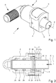
- Fig. 1 shows a quick-connect system 1 with a quick-connect device 2 according to a first embodiment and a fluid line end 3, wherein the fluid line end 3 is held in the quick-connect device 2 and secured against removal.
- the fluid line end 3 in the quick-connect device 2 used, in particular insertable is the fluid line end 3 in the quick-connect device 2 used, in particular insertable.
- the fluid line end piece 3 can be moved toward one another in the quick-connection device 2 in an insertion direction E.
- the fluid line end piece 3 can be pushed into the quick-connection device 2 in the direction of insertion E or the quick-connection device 2 can be placed or pushed onto the fluid line end piece 3 (along or opposite to the insertion direction).
- a continuous fluidic and / or mechanical connection of the fluid line end piece 3 with the quick-connection device 2 can be generated.
- the quick-connection device 2 preferably has a housing 4.
- the housing 4 has a passage 5 or an opening for receiving the fluid line end piece 3.
- the fluid line end piece 3 along an insertion direction E in the Quick connection device 2, preferably through the passage 5 of the housing 4, inserted and / or plugged.
- other solutions are possible.
- the fluid line end piece 3 can be secured against removal from the quick-connection device 2.
- the quick-connection device 2 is designed to hold the fluid line end piece 3-preferably in a form-fitting manner.
- the quick connect device 2 secures the fluid line end 3 against disconnection, removal and / or removal from or from the quick connect device 2.
- the quick-connection device 2 or the housing 4 preferably has a connection section A for connecting a further fluid line end piece.
- the connection section A is preferably arranged on a side of the housing 4 facing away from the passage 5.
- the quick connect device 2 can establish or form a continuous fluid connection or passage for liquids or gases between the fluid line end piece 3 and the connection section A or the further fluid line end piece.
- connection section A may be or have a fluid line connection means such as a hose nipple, a fitting or another connector for establishing a fluid connection.
- the connection section A may be an adapter or hose nipple, in particular for corrugated pipe, or have.
- the terminal portion A may be or have a tube with or without structuring on its outer peripheral surface.
- the connection section A preferably has radially extending alternating waves and valleys or ridges and grooves, preferably axisymmetric to a center or symmetry axis of the connection section A. These can correspond to an (inner) surface structure of a hose and / or to its tight connection serve (not shown).
- connection section A is designed to connect a fluid line end piece, which is designed differently than the fluid line end piece 3.
- the quick connection device 2 in this case adapts different fluid lines by producing a continuous fluidic and / or mechanical connection, which is closed to the environment.
- the fluid line end 3 is an open end of a rigid tube, whereas the further fluid line end connected or connectable to the terminal A is an end of a flexible tube, other tube, or other, similar or similar fluid conduit.
- connection portion A may be angled, such as in Fig. 1 shown.
- the fluid line end piece 3 is preferably round, at least substantially cylindrical and / or rotationally symmetrical to a longitudinal axis L and / or has a circular cross section, in particular perpendicular to the longitudinal axis L on.
- the longitudinal axis L preferably runs centrally along a channel formed by the fluid line end piece.
- the fluid line end piece 3 preferably has a cylindrical jacket-shaped wall which delimits the channel.
- the insertion direction E preferably runs parallel to the symmetry or longitudinal axis L of the fluid line end piece 3.
- the insertion direction E and the symmetry or longitudinal axis L lie one above the other, ie are identical.
- Fig. 2 shows a longitudinal section of the quick connect system 1 in a plane which includes the insertion direction E and / or the longitudinal axis L of the fluid line end piece 3.
- Fig. 2 is that the fluid line end 3 is positively secured to or in the quick-connect device 2 against removal.
- the quick connection device 2 for holding or securing the fluid line end piece 3 with a holding device 6 engages behind an undercut 10 of the fluid line end piece 3. In this way, locking of the fluid line end piece 3 in or on the quick connection device 2 is achieved.
- the holding device 6 preferably enables the production of a reversible connection.
- the holding device 6 on the one hand block or prevent separation of the fluid line end piece 3 from the quick-connection device 2, as in FIG Fig. 2 shown.
- the holding device 6 release the connection to release.
- the holding device 6, the lock cancel, with the undercut 10 is no longer engaged behind. This unlocking is preferably done manually.
- the holding device 6 has a securing element 7a and a further securing element 7b, in total therefore two securing elements 7a, 7b. In principle, however, there may be more than two securing elements 7a, 7b.
- the securing elements 7a, 7b of the holding device 6 are separately or independently movable. It is therefore possible that only one of the securing elements 7a, 7b is moved while the other securing element 7a, 7b does not change its position and vice versa.
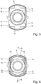
- Each of the securing elements 7a, 7b is in a securing position SP (see Fig. 5 ) and in a release position EP (see Fig. 6 ) Positionable and / or between the securing position SP and the Entommesposition EP, in particular linear or rectilinear, movable.
- the holding device 6 can have actuating elements 8 for actuating the securing elements 7a, 7b.
- each of the securing elements 7a, 7b associated with an actuating element 8.
- the securing elements 7a, 7b each have an actuating element 8.
- an actuating element 8 is connected to each of the securing elements 7a, 7b, preferably with positive locking and / or latching, or molded or integrally formed therewith.
- the actuating elements 8 are designed to move by manual actuation of an actuating surface, which is accessible in the installed state from the outside for manual actuation, the respective actuating element 8 associated securing element 7a, 7b. In this case, it is preferably provided that an actuation of the respective actuating element 8 moves the securing element 7a, 7b associated therewith into a releasing position EP.
- a return device 18 can be provided in order to move or bias the actuating element 8 respectively with the securing element 7a, 7b assigned thereto or fastened thereto in a securing position SP. Further properties and advantages of the actuating elements 8 will be described later on the basis of Fig. 8ff explained in detail.
- the fuse elements 7a, 7b are similar or similar in the representation example. They are arranged flush with the housing 4. They can be manually pressed into the housing 4. In this case, the securing elements 7a, 7b are moved into the releasing position E in order to enable a separation, that is to say a pulling apart of the quick-connection device 2 and the fluid line end piece 3 against the direction of insertion E is released.
- each of the securing elements 7a, 7b has a securing section 9.
- the securing portions are designed as flanks designed for latching engagement or have such.
- the securing sections 9 are designed to hold or fasten the fluid line end piece 3, so that inadvertent separation of the quick-connection device 2 from the fluid line end piece 3 is prevented.
- the fluid line end piece 3 preferably has an undercut 10, which in Fig. 2 is formed by an edge of a radially projecting bead.
- the rear 10 may also by a groove, one or more wells such. B. grooves or one or more protrusions may be formed.
- the undercut 10 completely surrounds or circumscribes the fluid line end piece 3, but alternatively it may also be provided incompletely, partially or only partially circumferentially and / or axially (along the insertion direction E). However, it is preferably about the insertion direction E axisymmetric or rotationally symmetrical structures such as one or more annular bead, annular grooves, rings, annular webs o. The like.
- the undercut 10 can preferably be engaged behind by the securing elements 7a, 7b. If the undercut 10 is realized by a groove, engage the securing elements 7a, 7b for securing the Fluid effetsend Publisheds 3 at the quick-connect device 2 in this. In the illustrated example, the undercut 10 is formed by the flank of a bead.
- the undercut 10 has a surface normal, which is directed counter to the insertion direction E.
- the securing elements 7a, 7b are designed to engage behind the undercut 10 when the securing elements 7a, 7b are moved from the releasing position EP into the securing position SP (transverse to the Surface normal). In this way, the fluid line end to the quick-connect device 2 is positively held, in particular latching.
- the securing elements 7a, 7b form latches or traps that engage behind the fluid line end piece 3, whereby the fluid line end piece 3 is held on or in the quick-connection device 2.
- the securing elements 7a, 7b are formed in the region of their securing sections 9 for engaging behind the undercut 10 of the fluid line end piece 3 in a common locking plane V extending transversely, particularly preferably vertically, to the insertion direction E.
- the undercut 10 at least when a force acts on the fluid line end piece 3 against the insertion direction E, abuts the securing sections 9. In this way, the fluid line end 3 can be supported.
- the direction in which the securing elements 7a, 7b are movable is also called the direction of movement B.
- the direction of movement B is transverse, in particular perpendicular to the insertion direction E.
- the movement of the securing elements 7a, 7b takes place in particular straight, linear and / or back and forth, and / or is guided accordingly.
- the securing elements 7a, 7b are preferably movable relative to one another and / or, in particular simultaneously, in opposite directions.
- the securing position SP is a position in which the securing element 7a, 7b or its securing portion 9 engages behind the undercut 10.
- the releasing position EP is preferably a position in which the securing element 7a, 7b or its securing section 9 does not engage behind the undercut 10 of the fluid line end piece 3.
- the securing elements 7a, 7b are each in their securing position SP.
- the securing elements 7a, 7b are each in their release position EP.
- the arming position EP and the securing position SP are preferably end positions of possible movements of the securing elements 7a, 7b, in particular along the direction of movement B.
- the fluid line end piece 3 is by positioning at least one of the securing elements 7a, 7b in its securing position SP, preferably by engaging behind the undercut 10 the securing portion 9 of the securing element 7a, 7b, secured against removal.
- the removal of the fluid line end piece 3 requires that the two securing elements 7a, 7b are simultaneously positioned in their releasing positions EP. As a result, removal of the fluid line end piece 3 is not possible and / or the fluid line end piece 3 is secured in the quick-connection device 2 if only one of the securing elements 7a, 7b is in its arming position EP or is positioned in its arming position EP.
- the securing elements 7a, 7b and / or their securing sections 9 for engaging behind the undercut 10 are preferably arranged with respect to the longitudinal axis or insertion direction E on different and / or opposite sides of the fluid line end piece 3.
- FIGS. 7 and 8 Reference is made, in which the securing elements 7a, 7b are shown for clarity without further parts of the quick-connect system 1 or the quick-connect device 2.
- the securing elements 7a, 7b are similar.
- the securing portions 9 of the two securing elements 7a, 7b are identical.
- the securing elements 7a, 7b are secured in or on the housing 4 against movement along, in particular opposite, the insertion direction E.
- the securing elements 7a, 7b are guided in or through the housing 4 for this purpose.
- the securing elements 7a, 7b are formed so complementary to the housing 4 that the securing elements 7a, 7b are secured in the housing 4 against movement along, in particular against, the insertion direction E.
- the securing elements 7a, 7b each have at least one, preferably two, guide sections 11.
- the guide sections 11 adjoin in the illustrated example at different ends of the securing section 9.
- the guide sections 11, together with the securing section 9, can form at least substantially the shape of a large U or a closed shape.
- the guide sections 11 of a securing element 7a, 7b and / or two different securing elements 7a, 7b are arranged parallel to one another.
- the guide sections 11 run or slide along one another or are designed for guiding the securing elements 7a, 7b. In particular, these guide sections 11 allow a linear sliding along the securing elements 7a, 7b.
- the guide portions 11 of two mutually corresponding or complementary securing elements 7a, 7b are formed as mutually corresponding or complementary sliding surfaces which preferably extend parallel to the locking plane V.
- the guide sections 11 are preferably designed such that the securing elements 7a, 7b are supported against one another in or against the insertion direction E.
- the guide portions 11 of each of the securing members 7a, 7b are preferably provided adjacent to the securing portion 9. In the installed state, the securing sections 9 with the guide sections 11 surround the fluid line end piece 3.
- the securing elements 7a, 7b are symmetrical to a plane which is spanned by the insertion direction E and the direction of movement B.
- the securing elements 7a, 7b are symmetrical to a plane which is spanned by the insertion direction E and the direction of movement B.
- the respective securing section 9 preferably projects beyond the guide sections 11, particularly preferably along the insertion direction E.
- the securing section 9 projects beyond the guide sections 11 in the insertion direction E and / or the securing section 9 projects beyond the guide sections 11 of the other securing element 7a , 7b against the insertion direction E.
- One or both of the securing elements 7a, 7b preferably have (in each case) a run-on slope 12.
- the ramps 12 are adapted to move the action of the fluid line end 3 or pressure on the ramps 12 in the insertion direction E, the fuse elements 7a, 7b in the armed position EP.
- the ramps 12 are in this case preferably arranged such that they narrow or taper an opening cross-section in the direction of insertion E.
- the respective ramp 12 includes, for example, an angle ⁇ of less than 40 °, more preferably less than 30 °, and / or more than 10 °, more preferably more than 20 °, with the insertion direction E.
- the securing sections 9 are designed to rest on the fluid line end piece 3.
- edges of the securing elements 7a, 7b extend at least partially complementary to a contour of the fluid line end piece 3 on a side facing the fluid line end piece 3, so that the fluid line end piece does not only hit the run-on slopes 12 at points and / or the securing elements 7a, 7b do not puncture the undercut 10 engage behind.
- the course of the edges is preferably a circular arc section which is complementary to a tubular fluid line end piece 3.
- the course may have a radius that at least substantially corresponds to the outer radius of the fluid line end piece 3. This allows for easy production of the connection and / or a robust securing by large contact surfaces and good power distribution or -abtechnisch.
- each of the securing elements 7a, 7b on its side facing away from the securing portion 9 or on the opposite side to an actuating portion 13, which may be formed by the preferably separately formed, with the remaining securing element 7a, 7b preferably positively connected actuating element 8.
- one of the securing elements 7a, 7b has an integrally formed or integrally formed with the securing element 7a, 7b actuating portion 13, while only the other of the securing elements 7a, 7b connected to a separately realized actuator 8 is connected or connected.
- the operating portion 13 preferably forms an outer surface of the quick-connect device 2.
- the operating portion 13 is an outer surface of the respective securing member 7a, 7b which is displaced / displaced by manual pressurization in the operating portion 13 from its securing position SP to the releasing position EP.
- the operating portions 13 of the securing elements 7 a, 7 b are preferably arranged on opposite sides of the quick-connection device 2.
- the securing elements 7a, 7b are movable toward one another or respectively into the quick-connection device 2 by means of the actuating sections 13, whereby the securing elements 7a, 7b are displaced from their securing positions SP into their releasing positions EP or displaceable.
- the actuating section 13 or the actuating element 8 preferably projects beyond the securing elements 7a, 7b, in any case the guide sections 11, along the insertion direction E. In this way, a covering and / or securing of the securing elements 7a, 7b can be achieved against falling out of the housing 4.
- the actuating portion 13, the securing portion 9 and the guide portions 11 form a self-contained structure with an opening for the passage of the Fluid effetsend Publisheds 3.
- the respective fuse element 7a, 7b with the securing portion 9, the guide portions 11 and the actuating portion 13 is annular.
- the guide portions 11, together with the securing portion 9 forming part of the securing elements 7a, 7b form a U-shaped structure, which is supplemented by attachment of the actuating element 8 to a closed or ring-like shape.
- the securing elements 7a, 7b in the position of use are preferably ring-like closed elements, which abut one another, are displaceable along one another and engage in one another laterally.
- the fluid line end 3 by both securing elements 7a, 7b or by the respective formed by the securing element 7a, 7b ring can be performed.
- the housing 4 and the / the securing element / s 7a, 7b are complementary to each other, so that the securing elements 7a, 7b are guided in the housing 4 transversely or perpendicular to the insertion direction E.
- the securing elements 7a, 7b have a guide element 14 that is designed to be complementary to a corresponding section of the housing 4 in particular.
- the guide member 14 may be a protruding element, in particular wherein this with a recess, for. B. a guide rail, the housing 4 corresponds or complementary thereto is formed. It is thus possible for the housing 4 to have guide elements 14 and for the securing elements 7a, 7b to have corresponding guide elements 14, such as recesses, indentations or guide rails.
- the securing elements 7a, 7b engage in one another and / or the securing elements 7a, 7b are guided in the direction of movement B against each other.
- the securing section 9 of one of the securing elements 7a, 7b adjoins or adjoins the guide sections 11 of the other of the securing elements 7a, 7b, in particular on the inside and / or transversely to the insertion direction E.
- other solutions are possible.
- At least one of the securing elements 7a, 7b, but preferably both securing elements 7a, 7b, are constructed in several parts.
- the actuating element 8 is initially realized separately from the remaining securing element 7a, 7b and can be connected here during assembly, so that as a result the securing element 7a, 7b is / are formed from the actuating element 8 and a second part, wherein the second part has the securing portion 9 or forms.
- the two-part design of the fuse elements 7a, 7b offers the advantage of a simple and reliable installation.
- the interlocking securing elements 7a, 7b are preferably inserted transversely to the insertion direction E in the housing. More preferably, the securing elements 7a, 7b are held in the housing 4 with the aid of an actuating element 8.
- the actuating element 8 is preferably positively and / or non-positively, in particular latching, with the remaining fuse element 7a, 7b connectable.
- the guide portions 11 may for this purpose have end attachment means, which correspond to fastening means of the actuating elements 8.
- These fastening devices are preferably designed for latching fastening of the actuating elements 8 or fastening of the actuating elements 8 by clipping.
- the guide portions 11 and the actuating portions 13 for the positive connection of the securing element 7a, 7b with the actuating element 8 locking means such as locking recesses 15 and locking projections 16.
- the latching depressions 15 are arranged on the outside or on the front side on the securing element 7a, 7b and on a side of the actuating elements 8 facing away from the actuating sections 13.
- the actuating element 8 has correspondingly complementary to the locking recesses 15 formed latching projections 16.
- the securing elements 7a, 7b have no detent recesses 15.
- a reverse arrangement is possible, that is, it is also possible that the actuating element has 8 locking recesses 15 and the securing element to complementary locking projections 16.
- the actuating element 8 is designed to move the securing elements 7a, 7b.
- an actuating element 8 is structurally realized separately from the securing elements 7a, 7b.
- each securing element 7a, 7b is associated with an actuating element 8, so that the quick-connection device 2 has two actuating elements 8.
- the actuating element 8 holds the securing element 7a, 7b, in the housing 4.
- the actuating elements 8 are provided in it Actuating openings 17 of the housing 4, which is particularly in Fig. 1 is shown.
- the actuators 8 cover housing parts, so that the actuators 8 can not slip into the housing 4 or through the housing 4.
- the actuating elements 8 are flush with the actuating openings 17 of the housing, in particular when the securing element 7a, 7b assigned to the actuating element 8 or the securing element 7a, 7b connected to the actuating element 8 is positioned in its securing position SP.
- the fuse element 7a, 7b is by moving, z. B. by pressing down or pushing the operating element 8 into the actuating opening 17 in the direction of the armed position EP movable and / or movable from its securing position SP in its Entêtsposition EP.
- the holding device 6 preferably has at least one, particularly preferably two or four, restoring devices 18.
- the return device 18 is designed to move the securing elements 7a, 7b into their securing position SP or in the direction of their securing position SP.
- the securing elements 7a, 7b are prestressed and / or prestressed by the restoring device 18 in the quick-connection device 2 into its securing position SP or in the direction of its securing position SP.
- the securing elements 7a, 7b are automatically movable into their securing position SP and / or can be positioned in their securing position SP.
- a manual actuation of the fuse elements 7a, 7b is not required because the automatic movement of the fuse elements 7a, 7b caused by the restoring device 18 and the restoring devices 18 and caused.
- the actuating element 8 has two return devices 18, which are formed in the example shown as flexible tabs or leaf springs.
- the actuating element 8 may have only one or more than two restoring devices 18 and / or other clamping elements such as spiral springs.
- the securing elements 7a, 7b (instead of the actuating element 8), the restoring devices 18 on.
- the restoring device 18 is arranged on the holding device 6. For example, a design via ring springs is conceivable here.
- the securing elements 7a, 7b are preferably movable into their securing position SP when the undercut 10 is in the insertion direction E behind the securing elements 7a, 7b.
- the securing elements 7a, 7b ie moved into their safety position SP or positioned in its safety position SP when the fluid line end 3 has been moved so far in the direction of insertion E or so far was inserted into the quick connector 2, that the undercut 10, the securing elements 7a, 7b has happened.
- the securing elements 7a, 7b are preferably by the action of the Fluid effetsend Publisheds 3 in the direction of insertion E on the ramps 12 automatically in the direction of their Entommesposition EP movable. Automatic here means that for moving the securing elements 7a, 7b in the direction of their armed position EP no manual actuation of the securing elements 7a, 7b by a user, not shown, is required.
- the securing elements 7a, 7b are moved by sliding along the wall of the Fluid effetsend thoroughlys 3 and / or the undercut 10 forming structure, preferably of the bead on the ramps 12 during insertion of the Fluid effetsend seras 3 in the direction of their Entommesposition EP.
- the ramps 12 on the angle ⁇ which allows the sliding along the Fluid effetsend Cambodias 3 and the undercut 10 on the securing elements 7a, 7b, in particular the securing portions 9.
- the angle ⁇ is chosen so that a self-locking of the Fluid effetsendwhis 3 prevents the ramps 12 and / or insertion of the Fluid effetsendwhis 3 is made possible in the quick-connect device 2.
- "exclusively" means that no further actuation and / or operation of the quick-connection device 2 is required for securing the fluid line end piece 3 against removal, except insertion.
- a manual actuation of the quick-connection device 2, in particular the securing elements 7a, 7b and / or the actuating elements 8, only for unlocking and / or removal of the Fluid effetsend Systemss 3 is required.
- the removal or the unlocking of the Fluid effetsend Cambodias 3 is not without or only by manually moving the securing elements 7a, 7b in their Entommesposition EP or by manual, in particular simultaneous positioning of the securing elements 7a, 7b in their Entommespositionen EP, preferably by a in the figures, not shown user, possible.
- securing elements 7a, 7b or the securing sections 9 without run-on slopes 12 is also possible. In this case, it may be necessary for the securing elements 7a, 7b to be moved by manual movement into their releasing position EP and / or to be positioned in their releasing position EP.
- the production of the fluidic connection and / or the securing of the fluid line end piece 3 against removal is / are preferably optically and / or acoustically signalable.
- the optical signaling and the acoustic signaling are independent of each other, but particularly preferably realized in combination.
- the securing elements 7a, 7b are designed, upon movement into the securing position SP, for example by impact, to produce an acoustic signal, in particular a click or click, in order to secure the fluid line end piece 3 against removal or engagement behind it the undercut 10 with the / the Sich mecanicslement (s) 7a, 7b to signal.
- an acoustic signal in particular a click or click
- the backup of the Fluid effetsend Publisheds 3 is signaled by the acoustic signal.
- the securing elements 7a, 7b automatically move into their securing position SP as soon as the undercut 10 has passed through the securing elements 7a, 7b upon insertion of the fluid line end piece 3.
- the restoring devices 18 then bring about rapid movement of the securing elements 7a, 7b into their securing position SP, so that the acoustic signal is generated by the impact of the securing elements 7a, 7b on the fluid line end piece 3 and / or on a section of the housing 4 provided for this purpose.
- the optical signal is preferably provided by an optical safety indicator 19, as shown in FIG FIGS. 12 and 13 shown in different views generated.
- the quick-connection device 2 has the securing indicator 19, which may be arranged at least substantially inside the housing 4 of the quick-connection device 2, which is also shown in FIGS Fig. 1 and 2 can be seen.
- the quick-connect device 2 is preferably designed so that the optical safety indicator 19 changes the external appearance of the quick-connect device 2. In this way, a connection state of the connection of the fluid line end piece 3 with the quick-connection device 2, in particular therefore a fluid connection and / or mechanical securing, can be signaled.
- the safety indicator 19 has at least one signal element 23, preferably two signal elements 23.
- the fuse indicator 19 is adapted to move the signal elements 23 by establishing the connection, whereby the connection state is signaled.
- the signal elements 23 which are initially sunk in the housing 4 are pushed out of the housing 4 by making the connection or vice versa.
- other solutions for optical signaling are also possible here.
- the safety indicator 19 is preferably actuatable mechanically by the fluid line end piece 3.
- the safety indicator 19 is preferably arranged in the insertion direction E behind a seal, in particular behind a sealing ring 25, and / or behind the locking plane V. In this way it can be achieved that the optical signal is generated only when the continuous fluidic connection is established.
- the fuse by means of the fuse elements 7a, 7b at least precedes the complete optical signaling or forms a prerequisite for this. It is therefore possible that the safety indicator 19 at least partially generates an optical signal, in particular is designed or is, when the fluidic equipment manufactured, the fluid line end piece 3 is not yet secured to the quick connector device 2.
- the safety indicator 19 preferably forms a resilient arrangement, which is arranged and designed in such a way that the fluid line end piece 3 acts on it when the connection is made, so that the optical signal is generated.
- the Safety indicator 19 is preferably deformed by the fluid line end piece 3 such that the optical signal is generated.
- the fuse indicator is resilient so that the optical signal disappears when the connection is disconnected.
- the safety indicator 19 is made in one piece.
- the safety indicator 19 is made of a flexible and / or elastic material, preferably a plastic.
- the safety indicator 19 is therefore preferably flexible and / or elastically deformable.
- the safety indicator 19 is arranged axially immovably in the housing 4.
- the safety indicator 19 is radially deformable, whereby the signaling can take place.
- the safety indicator 19 has an at least substantially rectangular and / or octahedral cross-section in the illustrated example. However, the safety indicator 19 may also be annular or annular. It is preferably arranged with its main extension perpendicular to the insertion direction E.
- the safety indicator 19 may have a plurality, preferably four, in particular identically formed and / or symmetrically arranged connecting webs 20 and a plurality, particularly preferably four, functional elements 21.
- the functional elements 21 are connected to one another by the connecting webs 20.
- the securing indicator 19 is held by the functional elements 21 in the housing 4 of the quick-connection device 2.
- the functional elements 21 are preferably designed to generate a movement and / or deformation of the securing indicator 19, in particular when the fluid line end piece 3 is inserted into the quick-connection device 2, and / or an optical signal.
- the functional elements 21 are therefore preferably designed differently, preferably wherein each two diametrically opposed functional elements 21 are formed identically or identically.
- the safety indicator 19 preferably has a closed basic shape, which forms an opening through which the fluid line end piece 3 is slidable. When the fluid conduit end piece 3 is moved in the insertion direction, it preferably displaces a portion of the safety indicator 19, thereby generating the optical signal.
- the safety indicator 19 is preferably moved or deformed by sliding along the wall and / or the undercut 10, preferably of the bead, on the ramps 22 during insertion of the Fluid effetsend Publisheds 3.
- the safety indicator 19 has a ramp 22.
- This ramp 22 is arranged so that the fluid line end 3, when it is moved to make the connection in the direction of insertion E, the securing indicator 19 moves or deformed.
- the signal element 23 is preferably adapted by movement from the housing 4 or in the housing 4 to signal a state of the connection. The movement changes the appearance of the quick connect device 2, thereby signaling the connection state.
- the signal element 23 is preferably movable directly through the fluid line end 3 to produce the optical signal.
- the signal element 23 may be cylindrical, dome-shaped and / or formed in the form of a nipple, pin or pins.
- two opposing functional elements 21 each have a run-on slope 22 and / or a signal element 23.
- the signal element 23 is arranged radially on the outside of the functional element 21.
- the ramp 22 is disposed radially inwardly of the functional element 21. In this way, by means of the ramp 22, the signal element 23 can be moved in a radially outward direction, whereby it projects beyond the housing 4 or from the housing 4 and thereby causes or generates the optical signal.
- the signal element (s) 23 may alternatively or additionally also be provided at other locations of the safety indicator 19. You can also perform another movement to signal the connection state. In particular, they can be arranged on the functional elements 21, which are arranged between the functional elements 21 which have the ramps 22. In this case, the signal elements 23 can be moved radially inward during production of the connection.
- the ramps 22 are arranged in the illustration example such that they taper a clear width in the direction of insertion E and / or that the distance between the mutually facing sides of the functional elements 21, the Run-on slopes 22 have, is reduced by the ramps 22 in the insertion direction E.
- the ramps 22 are preferably designed to slide off by inserting the fluid line end piece 3 at this.
- the angle ⁇ which includes the ramp 22 with the insertion direction E, is preferably less than 40 °, preferably less than 30 °, and / or more than 10 °, preferably more than 20 °.
- the signal elements 23 are preferably arranged in openings, openings or bores of the housing 4 provided for this purpose and / or movable, which is illustrated by way of example in FIG Fig. 1 can be seen.
- the signal elements 23 can be driven out of the housing 4 by the fluid line end piece 3 or pulled into the housing 4. This changes the appearance of the quick connect device 2, which causes the optical signaling.
- the safety indicator 19 completely surrounds the fluid line end piece 3 or the safety indicator 19 thus forms an opening into which the fluid line end piece 3 can enter or through which the fluid line end piece 3 can pass.
- the safety indicator 19 is deformable, whereby the at least one signal element 23 is deflected, preferably radially with respect to the insertion direction E or longitudinal axis L.
- the safety indicator 19 is preferably deformable such that at an increase in the distance between two arranged on opposite sides of the safety indicator 19 along a first imaginary axis functional elements 21 - for example by means of the ramps 22 - the distance between two other, along along a second imaginary, transverse or perpendicular to the first axis extending second axis and also on opposite sides of the fuse indicator 19 arranged functional elements 21, is increased and / or vice versa.
- the signal elements 23 are arranged radially to the insertion direction E so far inside that they for an (not shown) operator or user of the quick connector 2 or the quick connection system 1 from the outside in the housing 4 not are visible.
- the optical signaling of the fuse of the fluid line end piece 3 in this case is thus effected by an invisibility of the Signal elements 23 for the operator or user. In other words, by making the connection, the appearance of the quick connect device 2 changes.
- the visual signaling of the fuse of the fluid line end piece 3 by a visibility of the signal elements 23 for the operator or user takes place.
- the appearance of the quick connect device 2 changes by making the connection.
- the signal elements 23 are moved radially to the direction of insertion E so far that they are visible to an operator or user of the quick-connect device 2 or the quick-connect system 1 from the outside in or on the housing 4.
- the first variant ie signaling the fuse by invisibility of the signal elements 23, can be realized by a signal indicator 19, which according to the FIGS. 12 and 13 is trained.
- each functional element 21 either a ramp 22 or a signal element 23, wherein the signal elements 23 and / or the ramps 22 are each arranged on opposite functional elements 21.
- both a ramp 22 and a signal element 23 are arranged on two functional elements 21.
- the two further functional elements 21 have neither a ramp 22 nor a signal element 23.
- the safety indicator 19 has only two functional elements 21, preferably wherein each of the functional elements 21 has a ramp 22 and a signal element 23.
- the signal elements 23 are - biased radially inwards or outwards, for example, by the connecting webs 20. This makes it possible to act on the signal elements 23 against the bias by making the connection, so that the appearance of the quick-connect device 2 changes.
- the quick-connect device 2 is designed for the fluid-tight connection of the fluid line end piece 3.
- an environment-sealed, continuous passage such as a channel can be formed.
- the quick-connection device 2 preferably has a sealing device 24 for the fluid-tight connection of the fluid line end piece 3.
- the sealing device 24 is in particular in the Fig. 2 . 3 and 4 to recognize.
- the sealing device 24 is designed to connect the fluid line end piece 3 to a channel formed by the quick-connection device 2 such that a continuous, uninterrupted fluid connection is produced.
- the sealing device 24 connect the fluid line end piece 3 from the inside and / or outside fully dense.
- the sealing device 24 is arranged in the representation example within the housing 4.
- the sealing device 24 may be arranged between the fluid line end piece 3 and the housing 4.
- the sealing device 24 may be designed for fluid-tight sealing of gaps between the fluid line end piece 3 and the housing 4.
- the sealing device 24 preferably has one or two sealing rings 25 and / or a spacer sleeve 26 or is formed thereby.
- the sealing rings 25 and / or the spacer sleeve 26 are formed like a ring.
- the sealing device 24 preferably forms an opening into which the fluid line end piece 3 can be inserted, whereby a wall of the fluid line end piece 3 is sealed off from the quick-connection device 2.
- the sealing rings 25 and the spacer sleeve 26 include the fluid line end 3 at and / or after securing against removal.
- other constructive solutions are possible here, for. B. an arrangement of the sealing device 24 and the sealing ring 25 at the axial end of the Fluid effetsend Publisheds 3.
- the radius of the sealing ring 25 preferably corresponds to the radius of the Fluid effetsendFigs. 3
- FIGS. 1 to 13 illustrated first embodiment explained.
- FIGS. 14 to 17 illustrated, particularly preferred second embodiment of the present invention.
- Fig. 14 shows the second embodiment of the quick-connect system 1 and the quick-connect device 2 in an exploded view.
- the quick-connect device 2 has only one or exactly one securing element 7a. Accordingly, the housing 4 of the quick-connection device 2 for receiving (exactly) a securing element 7a is formed.
- the operation principle for securing the fluid line end piece 3 in the quick-connect device 2 in the second embodiment is similar or identical to the first embodiment. Accordingly, the above explanations preferably apply to the second embodiment as well, unless it is obviously contradictory. In particular, features described above in connection with the two fuse elements of the first embodiment are also features of the second embodiment with only one fuse element 7a.
- Fig. 15 shows the fuse element 7a in a front view, the viewing direction of the particular in Fig. 15 indicated insertion direction E corresponds.
- the securing element 7a preferably has two securing sections 9.
- the securing sections 9 are in particular formed integrally with the securing element 7a.
- the securing portions 9 of the securing element 7a are arranged opposite one another.
- securing element 7a is shown in its securing position SP.
- the fluid line end piece is secured in the quick-connect device 2 or can not be removed from the quick-connect device 2 when the securing element 7a is in the securing position SP.
- the securing element 7a is designed to engage behind the undercut 10 of the fluid line end piece 3 in the securing position with the securing sections 9.
- the securing element 7a is flexible and / or elastically deformable.
- the securing portions 9 are designed to be flexible and / or elastically deformable.
- the securing portions 9 can be moved apart, spread or bent apart, as in Fig. 15 also indicated by arrows.
- the securing element 7a or the securing sections 9 is / are preferably elastically deformable, with the result that the securing element 7a or the securing sections 9 automatically returns / return to the form or securing position SP shown in FIGS. 14 and 15 after a deformation or disassembly movement.
- the position in which the securing portions 9 are moved apart is the releasing position EP of the securing member 7a.
- the fluid line end piece 3 is preferably unlocked or removable from the quick-connection device 2 when the securing element 7a is in the release position EP.
- the release position EP is not explicitly shown in the figures, but in Fig. 15 indicated by arrows which symbolize the movement of the securing sections 9 between the securing position SP and the releasing position EP.
- the securing sections 9 are preferably movable by inserting the fluid line end piece 3 into the quick-connection device 2 by displacing it into the releasing position EP.
- the securing element 7a is preferably resilient in such a manner that the securing sections 9 are held in the securing position SP by means of the spring force caused by the securing element 7a or can be returned to the securing position SP. Further, it is preferred that the securing portions 9, in particular by insertion of the Fluid Arthursendrioss 3, are movable from the securing position SP in the armed position EP, wherein by deformation of the securing element 7a, a spring force is established, which biases the securing portions 9 in the direction of the securing position SP.
- the securing element 7a is preferably formed (mirror) symmetrically or axially symmetric, as in particular from Fig. 15 is apparent.
- the securing element 7a is preferably formed integrally with or out of the (two) securing sections 9 and the actuating element 8 or actuating section 13. Since the actuating element 8 preferably does not form a separate element or component in the second embodiment, only one actuating section 13 will be discussed below. However, it is also possible in the second embodiment that the actuating element 8 or the actuating portion 13 is formed analogously to the first embodiment by a separate component or element.
- the actuating portion 13 is preferably adapted to the shape or contour of the housing 4.
- the surface of the actuating portion 13 is preferably cylindrical or forms a portion of the lateral surface of a cylinder.
- any other shapes are possible.
- the securing portions 9 are integrally formed on the actuating portion 13.
- the actuating section 13 preferably runs transversely and / or between the securing sections 9, in particular so that the securing element 7 or the securing sections 9 and the actuating section 13 form / form an at least substantially U-shaped form.
- the securing element 7a forms a semi-open or unilaterally open or not completely closed structure.
- the actuating portion 13 is preferably arranged at the end on the securing portions 9 and vice versa.
- the securing sections 9 preferably have (in each case) a run-on slope 12.
- the securing element 7a according to the second embodiment has two run-on slopes 12, which are arranged in particular opposite one another and / or on opposite sides of the insertion direction E.
- a contact surface or contact surface for the fluid line end piece 3 is formed by the ramps 12 during insertion into the quick-connection device 2.
- the ramps 12 at least substantially conical surfaces.
- the ramps 12 are formed such that the chamfers 12 each form a portion of a lateral surface of an imaginary, tapering in the direction of insertion cone, at least in the in the FIGS. 14 and 15 illustrated securing position SP of the fuse element 7a.
- the largest radius of the cone hereby preferably corresponds or exceeds the outer radius of an open end side of the fluid line end piece 3.
- ramps 12 is preferably the implementation of the 5 facing or “front” surface of the securing portions 9 and the securing element 7a is greater than the implementation of 5 facing away from or “back” surface of the Securing sections 9 and the securing element 7a.
- the "rear” surface thus serves to lock or secure the fluid line end piece by engaging behind the undercut 10.
- an opening portion 28 is preferably formed between the securing portions 9, an opening portion 28 is preferably formed.
- the opening region 28 is preferably bounded laterally by the securing sections 9. These preferably limit a clear width, which falls below the outer radius of an open end side of the fluid line end piece 3.
- the size or area of the opening portion 28 is (reversibly) changeable.
- the inner sides 27 of the securing sections 9 extend-at least in a first region-preferably obliquely, in particular at an acute angle, to the direction of movement B.
- the opening section 28, which in particular narrows, is formed between the securing sections 9.
- the spacing of the inner sides 27 from each other decreases, at least in a first region.
- the inner side 27 of the securing element 7a or the securing sections 9 is in particular that side of the securing element 7a or the securing sections 9 which faces a fluid line end piece 3 secured in the quick-connection device 2.
- An outer side 32 of the securing element 7a or the securing sections 9 is that side of the securing element 7a or the securing sections 9 which faces away from a fluid line end piece 3 secured in the quick-connection device 2.
- the angle which the inner sides 27 enclose is preferably selected such that upon actuation of the securing element 7a or a movement of the securing element 7a in the direction of movement B by the lateral movement of the securing sections 9, the opening area 28 becomes so large that the fluid line end piece 3 is released or can be removed from the quick-connection device 2.
- the securing element 7a is designed such that upon insertion of the fluid line end piece 3 into the quick-connection device 2, the undercut 10, in particular the bead, strikes the chamfers 12 or contacts the chamfers 12.
- the securing portions 9 are moved or bent by the undercut 10 to the outside, preferably wherein the undercut 10 slides along the ramps 12, so that the opening portion 28 and the distance between the securing portions 9 is enlarged until the undercut 10 has passed the securing sections 9 or the securing element 7a (completely).
- the securing portions 9 and the securing element 7a are elastically deformable such that they move automatically or automatically into the securing position SP (back) after passing through the undercut 10. Thereby, a snap connection can be achieved by generating a sound for confirming the reaching of the securing position SP.
- the securing portions 9 are preferably movable from the securing position SP to the releasing position EP, so that a separation of the quick-connecting device 2 from the fluid line end piece 3 is made possible.
- the quick-connection device 2 may have a guide or mimic that causes a movement of the securing portions 9 in the release position EP upon actuation of the securing element 7a.
- the securing portions 9 are guided end side such that upon actuation of the actuating portion 13, the securing portions 9 are diverged end, resulting in deformation of the securing element 7a to a position of the securing portions 9, in which the fluid line end 3 is released or removed from the quick-connect device 2 ,
- ends of the securing sections 9 and the open ends of the securing element 7a are designed for latching retention of the securing element 7a in the quick-connection device 2, so that the securing element 7a is held in a form-fitting manner by insertion into the quick-connection device 2.
- the securing sections 9 preferably each have a sliding surface 30.
- the sliding surface 30 is preferably arranged in a second region or at a free end 29 of the securing sections 9.
- the first region of a securing section 9 preferably connects (directly) to the actuating section 13.
- the second region or the free end 29 of a securing section 9 preferably connects (directly) to the first region.
- the second region or the free end 29 is preferably arranged on the side facing away from the actuating portion 13 of the securing portion 9.
- the inner surfaces 27 of the first region and the sliding surfaces 30 of the second region and the free end 29 preferably include or form an obtuse angle.
- the distance between the sliding surfaces 30 increases with increasing distance from the first region.
- the securing sections 9 preferably have at least substantially the shape of an obtuse-angled triangle whose corner projects into the opening region 28 at the obtuse angle or narrows it.
- the sliding surfaces 30 are adapted to cause movement of the securing element 7a in the direction of movement B a moving apart or spreading of the securing portions 9. This serves, in particular, to ensure that a fluid line end piece 3 secured in the quick-connection device 2 can be unlocked or released again in a simple manner.
- the securing element 7a or the quick-connection device 2 is designed so that the fluid line end piece 3 can be unlocked or released for removal by pressing or pressing down the securing element 7a or actuating section 13 in the direction of movement B.
- a depression or pressing in of the securing element 7a preferably causes the securing sections 9 to move apart or spread apart, so that the opening area 28 narrowed in the securing position SP is enlarged and a removal of the fluid line end piece 3 is made possible.
- the securing element 7a can be biased counter to the direction of movement B and / or into the securing position SP.
- a restoring force is preferably generated in the securing element 7a or the securing sections 9 by the (elastic) deformation or spreading of the securing sections 9, which is opposite to the direction of movement B. and / or - provided that no force acts on the securing element 7a in the direction of movement - the securing element 7a is displaced counter to the direction of movement B and / or causes a movement of the securing element 7a or the securing sections 9 into the securing position SP.
- the securing element 7a is preferably movable from the securing position SP to the releasing position EP both by the action of the fluid line end piece 3 during insertion into the quick-connection device 2 and by pushing down the securing element 7a by a user (not shown), preferably with the securing sections 9 moved apart, spread apart or to be bent.
- the free ends 29 are each arranged in an associated receptacle 31 of the housing 4.
- the housing 4 preferably has two, in particular symmetrically arranged, receivers 31 for the free ends 29 of the securing sections 9.
- the receptacles 31 preferably have or form a mating surface for the sliding surface 30.
- the receptacles 31 preferably form a free space for the free ends 29, through which they can dive when moving in the direction of movement B.
- the receptacles 31 preferably form (in each case) an opening of the housing 4.
- the securing element 7a in particular the securing sections 9, preferably has or have a recess 33 on the outside 32.
- a movement of the securing portions 9 to the outside or in the armed position EP is made possible by the recess 33.
- the recess 33 is particularly avoided that the securing portions 9 come to rest with the outside 32 on the inside of the housing 4 and thus further movement of the securing portions 9 is blocked outwardly before the distance between the securing portions 9 is large enough to a pushing of the Fluid line end to allow.
- a space-saving and / or material-saving construction or production is made possible by the recess 33.
- the securing element 7a or have the securing portions 9 on the outside 32 on a shoulder 34 or form these.
- the shoulder 34 is preferably designed to secure the securing element 7a against falling out or removal from the housing 4.
- the shoulder preferably forms a transverse to the direction of movement B surface or has these.
- the shoulder 34 preferably forms a lower portion or lower boundary of the recess 33.
- the shoulder 34 is formed for a positive securing of the securing element 7a in the housing 4 or the receptacle 31.
- the free end 29 is preferably at least substantially V-shaped or triangular.
- the securing element 7a preferably has one or more, in particular integrally formed with the securing element 7a or integrally formed, restoring devices 18.
- the restoring device (s) 18 are in particular designed for, preferably automatic or automatic, movement of the securing element 7a into the securing position SP. They may be formed, for example, by one or more springs, in particular spring arms.
- the restoring devices 18 abut against or contact a fluid line end piece 3 secured in the quick-connection device 2.
- the restoring devices 18 are preferably flexible and / or elastically deformable. Preferably, the restoring devices 18 are designed to move the securing element 7a into the securing position SP or to hold it in the securing position SP if no force acts on the securing element 7a or the actuating section 13 in the direction of movement B. This is conducive to reliable securing of the fluid line end piece 3.
- the securing element 7a has two restoring devices 18, which are formed by two, in particular symmetrically arranged, curved or pretensioned spring cams counter to the direction of actuation B. Due to the curvature or bias a stronger restoring force can be achieved or play can be avoided.
- FIGS. 9 and 10 illustrated embodiment or in the form of (not curved or straight) leaf springs.
- the quick-connect device 2 has a safety indicator 19.
- the safety indicator 19 preferably has two, preferably separate or structurally separate, signal elements 23 or is formed by them.
- the signal elements 23 of the safety indicator 19 are preferably similar, identical and / or symmetrical to each other.
- the signal elements 23 are preferably movable independently of one another and / or uncoupled.
- Fig. 16 shows a signal element 23 of the safety indicator 19 in a perspective view.
- Fig. 17 two signal elements 23 arranged in the housing 4 of the quick-connection device 2 are shown.
- the signal elements 23 are arranged along the insertion direction E behind the securing element 7a or behind the locking plane V. In this way, it is ensured that a visual indication of the fuse reliably takes place only when the undercut 10 of the fluid line end piece 3 has passed the securing element 7a or the locking plane V or if the fluid line end piece 3 is secured against removal.
- the signal elements 23 are arranged symmetrically or mirror-inverted relative to each other and / or to the insertion direction E in the housing 4 of the quick-connection device 2.
- Fig. 17 the signal elements 23 are shown in different positions.
- the one on the left in Figure 17 shown position is referred to as "first position” and the right side in Fig. 17 shown position is hereinafter referred to as "second position".
- the first position corresponds to the Position that the signal element 23 occupies when no fluid line end 3 is arranged or inserted in the quick-connect device 2.
- the second position corresponds to the position occupied by the signal element 23 when a fluid line end piece 3 is fully inserted into the quick connect device 2 or secured in the quick connect device 2.
- the signal elements 23 are - at least when in the quick connector 2 no fluid line end 3 is secured or in the first position - preferably arranged completely within or flush with a surrounding surface of the housing 4 or arranged in the housing 4, that they are not protrude the housing 4.
- the signal element 23 for indicating the securing of the fluid line end piece 3 is at least partially moved out of the housing 4.
- the signal element 23 is preferably rotatably mounted in the housing 4 and / or formed thereto and / or arranged in the housing 4, that it is rotatable about a rotation axis D.
- the axis of rotation D is preferably arranged asymmetrically with respect to the signal element 23.
- the signal element 23 by a rotational movement or rotation (about the rotation axis D) from the first position to the second position movable and vice versa.
- the signal element 23 preferably has an actuating surface 35 for actuating or rotating the signal element 23.
- the actuating surface is arranged such that the Fluid effetsend Gla 3, the undercut 10 and the bead upon insertion of the Fluid effetsend Cambodias 3 in the quick-connect device 2 on the actuating surface 35 strikes or presses against this.
- the fuse is displayed, in particular automatically or automatically and / or during or by insertion of the fluid line end piece 3, by a rotation of the signal element 23 about the axis of rotation D, so that a part of the signal element 23 moves out of the housing 4.
- the rotation of the signal element 23 is effected by the fact that the fluid line end 3 pushes against the actuating surface 35 during insertion.
- the force exerted by the fluid line end piece 3 during insertion onto the signal element 23 or its actuating surface 35 causes the force preferably a rotational movement or rotation of the signal element 23 about the axis of rotation D.
- a rotation of the signal element 23 preferably takes place by more than 30 °, in particular at least approximately 45 °. Further rotation of the signal element 23 (beyond 45 ° or the second position) is preferably blocked by the signal element 23 in the second position or after a rotation of (approximately) 45 ° from the first position with a flat surface abuts an associated surface of the housing 4, as on the right in Fig. 17 is shown.
- the signal element 23 is preferably held in the second position or in the rotated or partially moved out of the housing 4 by the undercut 10.
- the undercut 10 of the secured in the quick connector 2 fluid line end 3 between the fuse element 7a and the signal elements 23 is arranged or clamped.
- the signal element 23 is preferably designed to encompass or enclose a strut arranged in the housing 4, so that the signal element 23 is rotatable about the strut and / or the strut forms or has the axis of rotation D.
- the signal element 23 can be clipped onto the strut for mounting.
- the signal element 23 preferably has a spring element 36.
- the spring element 36 is in particular designed to hold the signal element 23 in the first position or - preferably automatically or automatically - to move into the first position.
- the spring element 36 is preferably flexible and / or elastically deformable and / or designed as a spring arm.
- the spring element 36 protrudes plate-like or web-like from the signal element 23, in particular tangentially.
- the spring member 36 is bent in rotation from the first position to the second position (as well as in FIG Fig. 17 indicated), so that it causes a restoring force, which causes a rotation or biasing of the signal element 23 from the second position to the first position.
- the signal element 23 is designed by means of the spring element 36 to move back automatically or automatically into the housing 4 or the first position when the fluid line end piece 3 is removed from the quick-connection device 2.
Landscapes
- Engineering & Computer Science (AREA)
- General Engineering & Computer Science (AREA)
- Mechanical Engineering (AREA)
- Quick-Acting Or Multi-Walled Pipe Joints (AREA)
Applications Claiming Priority (1)
| Application Number | Priority Date | Filing Date | Title |
|---|---|---|---|
| DE102017001396.9A DE102017001396B4 (de) | 2017-02-14 | 2017-02-14 | Schnellverbindungsvorrichtung, Schnellverbindungssystem und Herstellungsverfahren |
Publications (2)
| Publication Number | Publication Date |
|---|---|
| EP3361135A1 true EP3361135A1 (fr) | 2018-08-15 |
| EP3361135B1 EP3361135B1 (fr) | 2021-04-07 |
Family
ID=61223837
Family Applications (1)
| Application Number | Title | Priority Date | Filing Date |
|---|---|---|---|
| EP18156756.1A Active EP3361135B1 (fr) | 2017-02-14 | 2018-02-14 | Dispositif de connexion rapide et système de connexion rapide |
Country Status (2)
| Country | Link |
|---|---|
| EP (1) | EP3361135B1 (fr) |
| DE (1) | DE102017001396B4 (fr) |
Cited By (3)
| Publication number | Priority date | Publication date | Assignee | Title |
|---|---|---|---|---|
| EP3667147A1 (fr) * | 2018-12-12 | 2020-06-17 | Yushin Precision Industrial Co., Ltd. | Ensemble connecteur rapide pour connecter un tuyau |
| WO2024074393A1 (fr) * | 2022-10-07 | 2024-04-11 | Norma Germany Gmbh | Système de raccordement pour guider un fluide, procédé correspondant, élément de raccordement, pièce enfichable et élément de recouvrement |
| WO2025129481A1 (fr) * | 2023-12-20 | 2025-06-26 | 廊坊舒畅汽车零部件有限公司 | Ensemble raccord rapide |
Citations (5)
| Publication number | Priority date | Publication date | Assignee | Title |
|---|---|---|---|---|
| US5052725A (en) | 1989-03-13 | 1991-10-01 | Colder Products Company | Two piece molded female coupling |
| DE19708377C1 (de) * | 1997-03-01 | 1998-06-18 | Raymond A & Cie | Lösbare Steckverbindung mit Montageanzeige |
| US20100276924A1 (en) * | 2009-04-30 | 2010-11-04 | Hutchinson | Snap-on coupling for connecting a fluid pipe to a rigid end fitting with a connection indicator and method of inspecting this connection |
| JP2013204793A (ja) * | 2012-03-29 | 2013-10-07 | Takagi Co Ltd | 継手 |
| DE202017101429U1 (de) * | 2017-03-13 | 2017-09-21 | LINDNER Aktiengesellschaft Decken-, Boden-, Trennwandsysteme | Steckverbindung für Rohrleitungen |
Family Cites Families (1)
| Publication number | Priority date | Publication date | Assignee | Title |
|---|---|---|---|---|
| JPH0618123Y2 (ja) | 1989-11-11 | 1994-05-11 | 日東工器株式会社 | 管継手のソケット |
-
2017
- 2017-02-14 DE DE102017001396.9A patent/DE102017001396B4/de active Active
-
2018
- 2018-02-14 EP EP18156756.1A patent/EP3361135B1/fr active Active
Patent Citations (5)
| Publication number | Priority date | Publication date | Assignee | Title |
|---|---|---|---|---|
| US5052725A (en) | 1989-03-13 | 1991-10-01 | Colder Products Company | Two piece molded female coupling |
| DE19708377C1 (de) * | 1997-03-01 | 1998-06-18 | Raymond A & Cie | Lösbare Steckverbindung mit Montageanzeige |
| US20100276924A1 (en) * | 2009-04-30 | 2010-11-04 | Hutchinson | Snap-on coupling for connecting a fluid pipe to a rigid end fitting with a connection indicator and method of inspecting this connection |
| JP2013204793A (ja) * | 2012-03-29 | 2013-10-07 | Takagi Co Ltd | 継手 |
| DE202017101429U1 (de) * | 2017-03-13 | 2017-09-21 | LINDNER Aktiengesellschaft Decken-, Boden-, Trennwandsysteme | Steckverbindung für Rohrleitungen |
Cited By (3)
| Publication number | Priority date | Publication date | Assignee | Title |
|---|---|---|---|---|
| EP3667147A1 (fr) * | 2018-12-12 | 2020-06-17 | Yushin Precision Industrial Co., Ltd. | Ensemble connecteur rapide pour connecter un tuyau |
| WO2024074393A1 (fr) * | 2022-10-07 | 2024-04-11 | Norma Germany Gmbh | Système de raccordement pour guider un fluide, procédé correspondant, élément de raccordement, pièce enfichable et élément de recouvrement |
| WO2025129481A1 (fr) * | 2023-12-20 | 2025-06-26 | 廊坊舒畅汽车零部件有限公司 | Ensemble raccord rapide |
Also Published As
| Publication number | Publication date |
|---|---|
| DE102017001396A1 (de) | 2018-08-16 |
| EP3361135B1 (fr) | 2021-04-07 |
| DE102017001396B4 (de) | 2025-10-23 |
Similar Documents
| Publication | Publication Date | Title |
|---|---|---|
| EP2880349B1 (fr) | Dispositif de raccordement rapide pour le raccordement libérable d'une conduite de fluide à une rallonge | |
| EP3149384B1 (fr) | Raccord enfichable pour conduites de fluide, muni d'une douille d'adaptation intérieure | |
| AT512397B1 (de) | Steckverbindung zum Verbinden von Leitungen für unter Druck gesetzte Flüssigkeiten oder Gase | |
| EP2454514B1 (fr) | Accouplement enfichable | |
| DE3424675C2 (de) | Schlauchkupplung | |
| DE102017208643B4 (de) | Kupplungselement zum Verbinden einer ersten fluidführenden Leitung mit einer zweiten fluidführenden Leitung sowie Kupplungsanordnung | |
| DE19831897A1 (de) | Steckkupplung zum Verbinden zweier Fluidleitungen | |
| EP2802801B1 (fr) | Connexion par enfichage libérable | |
| DE60201546T2 (de) | Schnellkupplung mit Kupplungsanzeiger | |
| EP3516284B1 (fr) | Ensemble connecteur enfichable pour conduites de fluide ainsi que procédé permettant de relier des conduites de fluide | |
| WO2009006962A1 (fr) | Raccord de conduite de fluide | |
| EP2283268B1 (fr) | Element de couplage enfichable pour conduites d'agent sous pression | |
| EP3361135B1 (fr) | Dispositif de connexion rapide et système de connexion rapide | |
| EP1969280B1 (fr) | Fiche pour systeme de connecteur enfichable | |
| DE102010035027A1 (de) | Verriegelungselement für einen Steckverbinder und Steckverbinder mit einem solchen Verriegelungselement | |
| EP3775658A1 (fr) | Dispositif de raccordement pour conduites de fluide | |
| DE102005044751B4 (de) | Steckverbinder für Medienleitungen | |
| WO2024042039A1 (fr) | Coupleur hydraulique, procédé de production d'un coupleur hydraulique et agencement de coupleur hydraulique | |
| DE102005046886A1 (de) | Lösbare Steckverbindung für Rohrleitungen | |
| EP1790899B1 (fr) | Raccord enfichable pour raccorder deux conduites de fluide | |
| DE202004016097U1 (de) | Steckverbinder für Medienleitungen | |
| DE19523830A1 (de) | Steckkupplung für Druckmittelsysteme | |
| DE102013200620A1 (de) | Verbindung für eine Niederdruckleitung | |
| EP3901509B1 (fr) | Connecteur enfichable détachable | |
| EP3159584A1 (fr) | Système de vannes |
Legal Events
| Date | Code | Title | Description |
|---|---|---|---|
| PUAI | Public reference made under article 153(3) epc to a published international application that has entered the european phase |
Free format text: ORIGINAL CODE: 0009012 |
|
| STAA | Information on the status of an ep patent application or granted ep patent |
Free format text: STATUS: THE APPLICATION HAS BEEN PUBLISHED |
|
| AK | Designated contracting states |
Kind code of ref document: A1 Designated state(s): AL AT BE BG CH CY CZ DE DK EE ES FI FR GB GR HR HU IE IS IT LI LT LU LV MC MK MT NL NO PL PT RO RS SE SI SK SM TR |
|
| AX | Request for extension of the european patent |
Extension state: BA ME |
|
| STAA | Information on the status of an ep patent application or granted ep patent |
Free format text: STATUS: REQUEST FOR EXAMINATION WAS MADE |
|
| 17P | Request for examination filed |
Effective date: 20190214 |
|
| RBV | Designated contracting states (corrected) |
Designated state(s): AL AT BE BG CH CY CZ DE DK EE ES FI FR GB GR HR HU IE IS IT LI LT LU LV MC MK MT NL NO PL PT RO RS SE SI SK SM TR |
|
| STAA | Information on the status of an ep patent application or granted ep patent |
Free format text: STATUS: EXAMINATION IS IN PROGRESS |
|
| 17Q | First examination report despatched |
Effective date: 20191017 |
|
| GRAP | Despatch of communication of intention to grant a patent |
Free format text: ORIGINAL CODE: EPIDOSNIGR1 |
|
| STAA | Information on the status of an ep patent application or granted ep patent |
Free format text: STATUS: GRANT OF PATENT IS INTENDED |
|
| INTG | Intention to grant announced |
Effective date: 20201029 |
|
| RAP1 | Party data changed (applicant data changed or rights of an application transferred) |
Owner name: UNIWELL ROHRSYSTEME GMBH & CO. KG |
|
| GRAS | Grant fee paid |
Free format text: ORIGINAL CODE: EPIDOSNIGR3 |
|
| GRAA | (expected) grant |
Free format text: ORIGINAL CODE: 0009210 |
|
| STAA | Information on the status of an ep patent application or granted ep patent |
Free format text: STATUS: THE PATENT HAS BEEN GRANTED |
|
| AK | Designated contracting states |
Kind code of ref document: B1 Designated state(s): AL AT BE BG CH CY CZ DE DK EE ES FI FR GB GR HR HU IE IS IT LI LT LU LV MC MK MT NL NO PL PT RO RS SE SI SK SM TR |
|
| REG | Reference to a national code |
Ref country code: GB Ref legal event code: FG4D Free format text: NOT ENGLISH |
|
| REG | Reference to a national code |
Ref country code: AT Ref legal event code: REF Ref document number: 1380124 Country of ref document: AT Kind code of ref document: T Effective date: 20210415 Ref country code: CH Ref legal event code: EP |
|
| REG | Reference to a national code |
Ref country code: DE Ref legal event code: R096 Ref document number: 502018004597 Country of ref document: DE |
|
| REG | Reference to a national code |
Ref country code: IE Ref legal event code: FG4D Free format text: LANGUAGE OF EP DOCUMENT: GERMAN |
|
| REG | Reference to a national code |
Ref country code: LT Ref legal event code: MG9D |
|
| REG | Reference to a national code |
Ref country code: NL Ref legal event code: MP Effective date: 20210407 |
|
| PG25 | Lapsed in a contracting state [announced via postgrant information from national office to epo] |
Ref country code: NL Free format text: LAPSE BECAUSE OF FAILURE TO SUBMIT A TRANSLATION OF THE DESCRIPTION OR TO PAY THE FEE WITHIN THE PRESCRIBED TIME-LIMIT Effective date: 20210407 Ref country code: HR Free format text: LAPSE BECAUSE OF FAILURE TO SUBMIT A TRANSLATION OF THE DESCRIPTION OR TO PAY THE FEE WITHIN THE PRESCRIBED TIME-LIMIT Effective date: 20210407 Ref country code: BG Free format text: LAPSE BECAUSE OF FAILURE TO SUBMIT A TRANSLATION OF THE DESCRIPTION OR TO PAY THE FEE WITHIN THE PRESCRIBED TIME-LIMIT Effective date: 20210707 Ref country code: FI Free format text: LAPSE BECAUSE OF FAILURE TO SUBMIT A TRANSLATION OF THE DESCRIPTION OR TO PAY THE FEE WITHIN THE PRESCRIBED TIME-LIMIT Effective date: 20210407 Ref country code: LT Free format text: LAPSE BECAUSE OF FAILURE TO SUBMIT A TRANSLATION OF THE DESCRIPTION OR TO PAY THE FEE WITHIN THE PRESCRIBED TIME-LIMIT Effective date: 20210407 |
|
| PG25 | Lapsed in a contracting state [announced via postgrant information from national office to epo] |
Ref country code: SE Free format text: LAPSE BECAUSE OF FAILURE TO SUBMIT A TRANSLATION OF THE DESCRIPTION OR TO PAY THE FEE WITHIN THE PRESCRIBED TIME-LIMIT Effective date: 20210407 Ref country code: RS Free format text: LAPSE BECAUSE OF FAILURE TO SUBMIT A TRANSLATION OF THE DESCRIPTION OR TO PAY THE FEE WITHIN THE PRESCRIBED TIME-LIMIT Effective date: 20210407 Ref country code: NO Free format text: LAPSE BECAUSE OF FAILURE TO SUBMIT A TRANSLATION OF THE DESCRIPTION OR TO PAY THE FEE WITHIN THE PRESCRIBED TIME-LIMIT Effective date: 20210707 Ref country code: LV Free format text: LAPSE BECAUSE OF FAILURE TO SUBMIT A TRANSLATION OF THE DESCRIPTION OR TO PAY THE FEE WITHIN THE PRESCRIBED TIME-LIMIT Effective date: 20210407 Ref country code: PT Free format text: LAPSE BECAUSE OF FAILURE TO SUBMIT A TRANSLATION OF THE DESCRIPTION OR TO PAY THE FEE WITHIN THE PRESCRIBED TIME-LIMIT Effective date: 20210809 Ref country code: PL Free format text: LAPSE BECAUSE OF FAILURE TO SUBMIT A TRANSLATION OF THE DESCRIPTION OR TO PAY THE FEE WITHIN THE PRESCRIBED TIME-LIMIT Effective date: 20210407 Ref country code: IS Free format text: LAPSE BECAUSE OF FAILURE TO SUBMIT A TRANSLATION OF THE DESCRIPTION OR TO PAY THE FEE WITHIN THE PRESCRIBED TIME-LIMIT Effective date: 20210807 Ref country code: GR Free format text: LAPSE BECAUSE OF FAILURE TO SUBMIT A TRANSLATION OF THE DESCRIPTION OR TO PAY THE FEE WITHIN THE PRESCRIBED TIME-LIMIT Effective date: 20210708 |
|
| REG | Reference to a national code |
Ref country code: DE Ref legal event code: R097 Ref document number: 502018004597 Country of ref document: DE |
|
| PG25 | Lapsed in a contracting state [announced via postgrant information from national office to epo] |
Ref country code: SK Free format text: LAPSE BECAUSE OF FAILURE TO SUBMIT A TRANSLATION OF THE DESCRIPTION OR TO PAY THE FEE WITHIN THE PRESCRIBED TIME-LIMIT Effective date: 20210407 Ref country code: SM Free format text: LAPSE BECAUSE OF FAILURE TO SUBMIT A TRANSLATION OF THE DESCRIPTION OR TO PAY THE FEE WITHIN THE PRESCRIBED TIME-LIMIT Effective date: 20210407 Ref country code: EE Free format text: LAPSE BECAUSE OF FAILURE TO SUBMIT A TRANSLATION OF THE DESCRIPTION OR TO PAY THE FEE WITHIN THE PRESCRIBED TIME-LIMIT Effective date: 20210407 Ref country code: ES Free format text: LAPSE BECAUSE OF FAILURE TO SUBMIT A TRANSLATION OF THE DESCRIPTION OR TO PAY THE FEE WITHIN THE PRESCRIBED TIME-LIMIT Effective date: 20210407 Ref country code: RO Free format text: LAPSE BECAUSE OF FAILURE TO SUBMIT A TRANSLATION OF THE DESCRIPTION OR TO PAY THE FEE WITHIN THE PRESCRIBED TIME-LIMIT Effective date: 20210407 Ref country code: DK Free format text: LAPSE BECAUSE OF FAILURE TO SUBMIT A TRANSLATION OF THE DESCRIPTION OR TO PAY THE FEE WITHIN THE PRESCRIBED TIME-LIMIT Effective date: 20210407 Ref country code: CZ Free format text: LAPSE BECAUSE OF FAILURE TO SUBMIT A TRANSLATION OF THE DESCRIPTION OR TO PAY THE FEE WITHIN THE PRESCRIBED TIME-LIMIT Effective date: 20210407 |
|
| PLBE | No opposition filed within time limit |
Free format text: ORIGINAL CODE: 0009261 |
|
| STAA | Information on the status of an ep patent application or granted ep patent |
Free format text: STATUS: NO OPPOSITION FILED WITHIN TIME LIMIT |
|
| 26N | No opposition filed |
Effective date: 20220110 |
|
| PG25 | Lapsed in a contracting state [announced via postgrant information from national office to epo] |
Ref country code: IS Free format text: LAPSE BECAUSE OF FAILURE TO SUBMIT A TRANSLATION OF THE DESCRIPTION OR TO PAY THE FEE WITHIN THE PRESCRIBED TIME-LIMIT Effective date: 20210807 Ref country code: AL Free format text: LAPSE BECAUSE OF FAILURE TO SUBMIT A TRANSLATION OF THE DESCRIPTION OR TO PAY THE FEE WITHIN THE PRESCRIBED TIME-LIMIT Effective date: 20210407 |
|
| PG25 | Lapsed in a contracting state [announced via postgrant information from national office to epo] |
Ref country code: IT Free format text: LAPSE BECAUSE OF FAILURE TO SUBMIT A TRANSLATION OF THE DESCRIPTION OR TO PAY THE FEE WITHIN THE PRESCRIBED TIME-LIMIT Effective date: 20210407 |
|
| PG25 | Lapsed in a contracting state [announced via postgrant information from national office to epo] |
Ref country code: MC Free format text: LAPSE BECAUSE OF FAILURE TO SUBMIT A TRANSLATION OF THE DESCRIPTION OR TO PAY THE FEE WITHIN THE PRESCRIBED TIME-LIMIT Effective date: 20210407 |
|
| REG | Reference to a national code |
Ref country code: CH Ref legal event code: PL |
|
| REG | Reference to a national code |
Ref country code: BE Ref legal event code: MM Effective date: 20220228 |
|
| PG25 | Lapsed in a contracting state [announced via postgrant information from national office to epo] |
Ref country code: LU Free format text: LAPSE BECAUSE OF NON-PAYMENT OF DUE FEES Effective date: 20220214 |
|
| PG25 | Lapsed in a contracting state [announced via postgrant information from national office to epo] |
Ref country code: LI Free format text: LAPSE BECAUSE OF NON-PAYMENT OF DUE FEES Effective date: 20220228 Ref country code: IE Free format text: LAPSE BECAUSE OF NON-PAYMENT OF DUE FEES Effective date: 20220214 Ref country code: CH Free format text: LAPSE BECAUSE OF NON-PAYMENT OF DUE FEES Effective date: 20220228 |
|
| PG25 | Lapsed in a contracting state [announced via postgrant information from national office to epo] |
Ref country code: BE Free format text: LAPSE BECAUSE OF NON-PAYMENT OF DUE FEES Effective date: 20220228 |
|
| PG25 | Lapsed in a contracting state [announced via postgrant information from national office to epo] |
Ref country code: HU Free format text: LAPSE BECAUSE OF FAILURE TO SUBMIT A TRANSLATION OF THE DESCRIPTION OR TO PAY THE FEE WITHIN THE PRESCRIBED TIME-LIMIT; INVALID AB INITIO Effective date: 20180214 |
|
| REG | Reference to a national code |
Ref country code: AT Ref legal event code: MM01 Ref document number: 1380124 Country of ref document: AT Kind code of ref document: T Effective date: 20230214 |
|
| PG25 | Lapsed in a contracting state [announced via postgrant information from national office to epo] |
Ref country code: AT Free format text: LAPSE BECAUSE OF NON-PAYMENT OF DUE FEES Effective date: 20230214 |
|
| PG25 | Lapsed in a contracting state [announced via postgrant information from national office to epo] |
Ref country code: MK Free format text: LAPSE BECAUSE OF FAILURE TO SUBMIT A TRANSLATION OF THE DESCRIPTION OR TO PAY THE FEE WITHIN THE PRESCRIBED TIME-LIMIT Effective date: 20210407 Ref country code: CY Free format text: LAPSE BECAUSE OF FAILURE TO SUBMIT A TRANSLATION OF THE DESCRIPTION OR TO PAY THE FEE WITHIN THE PRESCRIBED TIME-LIMIT Effective date: 20210407 Ref country code: AT Free format text: LAPSE BECAUSE OF NON-PAYMENT OF DUE FEES Effective date: 20230214 |
|
| PG25 | Lapsed in a contracting state [announced via postgrant information from national office to epo] |
Ref country code: MT Free format text: LAPSE BECAUSE OF FAILURE TO SUBMIT A TRANSLATION OF THE DESCRIPTION OR TO PAY THE FEE WITHIN THE PRESCRIBED TIME-LIMIT Effective date: 20210407 |
|
| PG25 | Lapsed in a contracting state [announced via postgrant information from national office to epo] |
Ref country code: TR Free format text: LAPSE BECAUSE OF FAILURE TO SUBMIT A TRANSLATION OF THE DESCRIPTION OR TO PAY THE FEE WITHIN THE PRESCRIBED TIME-LIMIT Effective date: 20210407 |
|
| PGFP | Annual fee paid to national office [announced via postgrant information from national office to epo] |
Ref country code: GB Payment date: 20260219 Year of fee payment: 9 |
|
| PGFP | Annual fee paid to national office [announced via postgrant information from national office to epo] |
Ref country code: DE Payment date: 20260219 Year of fee payment: 9 |
|
| PGFP | Annual fee paid to national office [announced via postgrant information from national office to epo] |
Ref country code: AT Payment date: 20260410 Year of fee payment: 5 |
|
| PGFP | Annual fee paid to national office [announced via postgrant information from national office to epo] |
Ref country code: FR Payment date: 20260218 Year of fee payment: 9 |