EP3361618B1 - Topologie à cinq commutateurs - Google Patents
Topologie à cinq commutateurs Download PDFInfo
- Publication number
- EP3361618B1 EP3361618B1 EP18156597.9A EP18156597A EP3361618B1 EP 3361618 B1 EP3361618 B1 EP 3361618B1 EP 18156597 A EP18156597 A EP 18156597A EP 3361618 B1 EP3361618 B1 EP 3361618B1
- Authority
- EP
- European Patent Office
- Prior art keywords
- switch
- inverter
- voltage
- intermediate circuit
- motor
- Prior art date
- Legal status (The legal status is an assumption and is not a legal conclusion. Google has not performed a legal analysis and makes no representation as to the accuracy of the status listed.)
- Active
Links
Images


Classifications
-
- H—ELECTRICITY
- H02—GENERATION; CONVERSION OR DISTRIBUTION OF ELECTRIC POWER
- H02M—APPARATUS FOR CONVERSION BETWEEN AC AND AC, BETWEEN AC AND DC, OR BETWEEN DC AND DC, AND FOR USE WITH MAINS OR SIMILAR POWER SUPPLY SYSTEMS; CONVERSION OF DC OR AC INPUT POWER INTO SURGE OUTPUT POWER; CONTROL OR REGULATION THEREOF
- H02M5/00—Conversion of AC power input into AC power output, e.g. for change of voltage, for change of frequency, for change of number of phases
- H02M5/40—Conversion of AC power input into AC power output, e.g. for change of voltage, for change of frequency, for change of number of phases with intermediate conversion into DC
- H02M5/42—Conversion of AC power input into AC power output, e.g. for change of voltage, for change of frequency, for change of number of phases with intermediate conversion into DC by static converters
- H02M5/44—Conversion of AC power input into AC power output, e.g. for change of voltage, for change of frequency, for change of number of phases with intermediate conversion into DC by static converters using discharge tubes or semiconductor devices to convert the intermediate DC into AC
- H02M5/453—Conversion of AC power input into AC power output, e.g. for change of voltage, for change of frequency, for change of number of phases with intermediate conversion into DC by static converters using discharge tubes or semiconductor devices to convert the intermediate DC into AC using devices of a triode or transistor type requiring continuous application of a control signal
- H02M5/458—Conversion of AC power input into AC power output, e.g. for change of voltage, for change of frequency, for change of number of phases with intermediate conversion into DC by static converters using discharge tubes or semiconductor devices to convert the intermediate DC into AC using devices of a triode or transistor type requiring continuous application of a control signal using semiconductor devices only
-
- H—ELECTRICITY
- H02—GENERATION; CONVERSION OR DISTRIBUTION OF ELECTRIC POWER
- H02M—APPARATUS FOR CONVERSION BETWEEN AC AND AC, BETWEEN AC AND DC, OR BETWEEN DC AND DC, AND FOR USE WITH MAINS OR SIMILAR POWER SUPPLY SYSTEMS; CONVERSION OF DC OR AC INPUT POWER INTO SURGE OUTPUT POWER; CONTROL OR REGULATION THEREOF
- H02M7/00—Conversion of AC power input into DC power output; Conversion of DC power input into AC power output
- H02M7/42—Conversion of DC power input into AC power output without possibility of reversal
- H02M7/44—Conversion of DC power input into AC power output without possibility of reversal by static converters
- H02M7/48—Conversion of DC power input into AC power output without possibility of reversal by static converters using discharge tubes with control electrode or semiconductor devices with control electrode
- H02M7/53—Conversion of DC power input into AC power output without possibility of reversal by static converters using discharge tubes with control electrode or semiconductor devices with control electrode using devices of a triode or transistor type requiring continuous application of a control signal
- H02M7/537—Conversion of DC power input into AC power output without possibility of reversal by static converters using discharge tubes with control electrode or semiconductor devices with control electrode using devices of a triode or transistor type requiring continuous application of a control signal using semiconductor devices only, e.g. single switched pulse inverters
- H02M7/5387—Conversion of DC power input into AC power output without possibility of reversal by static converters using discharge tubes with control electrode or semiconductor devices with control electrode using devices of a triode or transistor type requiring continuous application of a control signal using semiconductor devices only, e.g. single switched pulse inverters in a bridge configuration
- H02M7/53871—Conversion of DC power input into AC power output without possibility of reversal by static converters using discharge tubes with control electrode or semiconductor devices with control electrode using devices of a triode or transistor type requiring continuous application of a control signal using semiconductor devices only, e.g. single switched pulse inverters in a bridge configuration with automatic control of output voltage or current
-
- H—ELECTRICITY
- H02—GENERATION; CONVERSION OR DISTRIBUTION OF ELECTRIC POWER
- H02P—CONTROL OR REGULATION OF ELECTRIC MOTORS, ELECTRIC GENERATORS OR DYNAMO-ELECTRIC CONVERTERS; CONTROLLING TRANSFORMERS, REACTORS OR CHOKE COILS
- H02P3/00—Arrangements for stopping or slowing electric motors, generators, or dynamo-electric converters
- H02P3/06—Arrangements for stopping or slowing electric motors, generators, or dynamo-electric converters for stopping or slowing an individual dynamo-electric motor or dynamo-electric converter
- H02P3/18—Arrangements for stopping or slowing electric motors, generators, or dynamo-electric converters for stopping or slowing an individual dynamo-electric motor or dynamo-electric converter for stopping or slowing an AC motor
- H02P3/22—Arrangements for stopping or slowing electric motors, generators, or dynamo-electric converters for stopping or slowing an individual dynamo-electric motor or dynamo-electric converter for stopping or slowing an AC motor by short-circuit or resistive braking
Definitions
- the invention relates to a circuit topology for a frequency converter for operating an electrical machine on an electrical AC voltage network.
- the invention also relates to a method for operating a motor on the frequency converter.
- Known frequency converters have a feed unit which is coupled to an inverter via a DC voltage intermediate circuit.
- An intermediate circuit capacitor is generally provided in the DC voltage intermediate circuit.
- a frequency converter is known.
- the basic functionality of a frequency converter is known.
- electrical energy can be exchanged between an AC voltage network on the supply side and an electrical machine by means of a frequency converter.
- the electric machine can in principle be an electric motor or a generator.
- the exchange of electrical energy takes place either from the AC voltage network to the electrical machine or in the opposite direction.
- the present invention is primarily concerned with a frequency converter in a topology for controlling an electric motor and in particular an EC motor. If the electrical machine is accordingly an electric motor or a universally operable machine in motor mode, the feed unit acts as a rectifier, by means of which electrical energy is fed from the AC voltage network into the intermediate circuit.
- the frequency converter It is possible by means of the frequency converter to carry out a conversion between an alternating mains voltage with a predetermined mains frequency and an alternating voltage with a certain frequency required for operating the electrical machine. For this purpose, a 2-stage voltage conversion takes place.
- the line-side infeed unit of the frequency converter converts between the AC line voltage and a DC voltage of the DC voltage intermediate circuit. This in turn connects the feed unit with an inverter.
- the inverter has the task of converting the DC link voltage into a suitable AC voltage for the motor.
- a so-called intermediate circuit capacitor with a sufficiently large capacitance ensures that a ripple generated in the intermediate circuit DC voltage is also used for the subsequent voltage conversion the inverter is smoothed.
- the intermediate circuit capacitor capacity is preferably also large enough to enable uninterrupted operation of the electrical machine in the event of a brief failure of the supply-side AC line voltage.
- the rectification After the supply unit has been connected to the phases of the AC voltage network, the rectification generates the DC voltage in the intermediate circuit, as a result of which the intermediate circuit capacitor is charged. After the intermediate circuit capacitor has been charged to such an extent that the intermediate circuit DC voltage has reached the required voltage value, the motor can be operated on it.
- the inverter generates an alternating voltage so that a three-phase current flows in the strands of the motor. As an inverter this is z. B. an H-bridge or full bridge is known, which is not explained in detail.
- the diodes of the inverter automatically feed back energy from the motor to the electronics and a negative torque is generated, which reduces or reduces the speed of the motor . the motor is braked.
- a correspondingly large electrolytic capacitor helps to keep the voltage drops low, but at the same time, depending on the design, causes a reduction in the power factor of the frequency converter through a distorted current consumption of the rectifier from the mains.
- a basic idea of the present invention consists in a 5-switch topology in which four switches are arranged as four-quadrant controllers and an additional switch is arranged or connected in the conduction path in the inverter-side part of the DC voltage intermediate circuit.
- the additional switch is clocked with a certain high-frequency PWM frequency.
- the switches in the four-quadrant controller are only clocked at low frequencies in order to commutate the motor currents. If additional switches are closed, a current flow via the intermediate circuit is enabled and the motor is supplied with energy. However, if the additional switch is opened, the motor is set to freewheel.
- a frequency converter for operating an electrical machine on an electrical AC voltage network having a rectifying feed unit and an inverter which are connected to one another via a DC voltage intermediate circuit.
- An intermediate circuit capacitor is provided in the DC voltage intermediate circuit.
- the inverter is implemented as a four-quadrant controller with four switches, with a line path in the inverter-side part of the DC voltage intermediate circuit that connects the DC voltage intermediate circuit with the Inverter connects, a clockable switch is arranged, which is designed to selectively open or close the line path or for clocked operation.
- the additional switch or the corresponding switching device between the DC voltage intermediate circuit and the inverter can be used as a semiconductor switch with a parallel-connected freewheeling diode, such as. B. be implemented as a MOSFET or from two series or series-connected semiconductor switches, each with a parallel-connected free-wheeling diode, the forward direction of the free-wheeling diodes then being opposite.
- a diode is provided in a forward direction in the switching device or the corresponding line path for realizing the additional switch, which diode is designed to prevent a current flow from the inverter-side part of the DC voltage intermediate circuit to the feed unit.
- a further aspect of the present invention relates to a method for operating a frequency converter as described above in which the said additional switch is clocked by means of PWM clocking.
- switches of the four-quadrant controller are clocked in a low-frequency cycle during operation of the electrical machine, while the additional switch in the line path in the inverter-side part of the DC voltage intermediate circuit is clocked in a high-frequency cycle that is preferably several times higher than the low frequency clock.
- the operation is advantageously carried out in such a way that when the switch is opened, the motor is set to freewheel, while when the switch is closed, the flow of current via the DC voltage intermediate circuit to the motor is enabled, with two of the switches in the quadrant controller for changing between freewheeling and motor supply do not have to be switched, while by means of the switch position of the other two switches, a current through the first two switches of the Vierqaudrantenstellers is controlled, whereby the losses within the inverter are distributed to the respective switch.
- the method is advantageously designed in such a way that the commutation of the switches of the four-quadrant controller only takes place in order to commutate the sign of the voltage applied to the motor.
- the switch in the line path in the inverter-side part of the DC voltage intermediate circuit to the inverter is opened as soon as the intermediate circuit DC voltage falls below the terminal voltage generated by the electrical machine, which means that induced energy is fed back from the electrical machine in the DC voltage intermediate circuit is specifically prevented.
- the frequency converter 1 is designed to operate an electrical machine 50, which in the present exemplary embodiment is an electric motor 50.
- the frequency converter 1 is connected to an electrical AC voltage network 10, the frequency converter 1 having a rectifying feed unit 20, namely a rectifier made up of four diodes DG1, DG2 DG3, DG4 and an inverter 40, which are connected to one another via a DC voltage intermediate circuit 30.
- the DC voltage intermediate circuit 30 has an intermediate circuit capacitor 31.
- the inverter 40 is implemented as a four-quadrant controller with four power switches S1, S2, S3, S4 (such as MOSFETs). It can be seen that in the line path 32 in the inverter-side Part of the DC voltage intermediate circuit 30, which connects the DC voltage intermediate circuit 30 to the inverter 40, a clockable switch S5 is arranged, which is designed to optionally open or close the line path 32 or for clocked operation.
- the switch S5 or the corresponding switching device between the DC voltage intermediate circuit 30 and the inverter 40 can, as in FIG Figure 4 shown, either as a semiconductor switch with a parallel-connected freewheeling diode (middle view of the Figure 4 ) or from two series-connected semiconductor switches S5 1 , S5 2 each with a parallel-connected free-wheeling diode D1, D2, the forward direction of the free-wheeling diodes D1, D2 (right view of the Figure 4 ) is opposite.
- the following considerations relate, for example, to a positive current flow through the motor from terminal 51 to terminal 52, with the motor being operated as a drive.
- switch S5 is open. Due to the positive current flow through the motor winding of the motor 50 before the switch is opened and the energy stored in the motor 50 as a result, the current flow through the motor winding is initially maintained. The stream closes according to the in Figure 3 drawn current paths. There is therefore no voltage between terminals 51 and 52 of motor 50.
- Switches S1 and S4 must be used to switch between supply (as in Figure 2) and freewheeling (as in Figure 3 ) cannot be switched.
- the switches S1, S2, S3, S4 only need to be commutated if the sign of the voltage applied to the motor 50 must be commutated. It can be seen that when the motor current is positive and switch S5 is closed, no current flows through semiconductors S2 and S3.
- the Figure 5 shows the current course curves through the switches S1, S2, S3, S4 and S5 of the circuit topology described with a clocked switch S5.
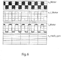
- the semiconductor switches S1, S2, S3, S4 change the polarity of the voltage applied to the motor 50, which in the Figure 6 corresponds to the envelope of u_Motor.
- the clocking of switch S5 then creates a square-wave voltage.
- the motor current i_ motor and the EMF u_ i_ motor are in phase with one another, as a result of which energy is transferred to the motor 50, whereby the in the Figure 6 illustrated speed n_ mech_ rpm increases in the acceleration phase.
Landscapes
- Engineering & Computer Science (AREA)
- Power Engineering (AREA)
- Inverter Devices (AREA)
Claims (7)
- Convertisseur de fréquence (1) pour le fonctionnement d'une machine électrique (50) sur un réseau de tension alternative électrique (10), dans lequel le convertisseur de fréquence (1) présente une unité d'alimentation redresseur (20) et un onduleur (40), qui sont interconnectés l'un avec l'autre par le biais d'un circuit intermédiaire de tension continue (30) avec un condensateur de circuit intermédiaire (31), dans lequel l'onduleur (40) est réalisé en tant que pont en H avec quatre commutateurs (S1, S2, S3, S4) dans un pont en H ainsi qu'un commutateur cyclique (S5), qui est agencé dans un chemin de conduction (32) dans la partie côté onduleur du circuit intermédiaire de tension continue (30), lequel relie le circuit intermédiaire de tension continue (30) à l'onduleur (40), et le commutateur cyclique (S5) est réalisé pour l'ouverture ou [a fermeture sélective du chemin de conduction (32) ou pour le fonctionnement cadencé, caractérisé en ce que le commutateur (S5) est réalisé en tant que commutateur cadencé comprenant deux commutateurs semi-conducteurs (S51, S52) montés en série avec respectivement une diode de roue libre (D1, D2) montée en parallèle, dans lequel le sens de passage des diodes de roue libre (D1, D2) est inverse et dans lequel les commutateurs (S1, S2, S3, S4) sont cadencés dans un cycle basse fréquence, pendant que le commutateur (S5) est cadencé dans un cycle haute fréquence, qui est supérieur de préférence d'un multiple au cycle basse fréquence et dans lequel une diode (D1, D2) du commutateur (S5) est conçue pour empêcher un flux de courant de la partie côté onduleur du circuit intermédiaire de tension continue (30) à l'unité d'alimentation (20).
- Convertisseur de fréquence (1) selon la revendication 1, dans lequel l'onduleur (40) est réalisé en tant qu'onduleur triphasé,
- Procédé de fonctionnement d'un convertisseur de fréquence (1) selon l'une quelconque des revendications 1 ou 2 précédentes, dans lequel les commutateurs (51, S2, 83, S4) sont cadencés dans une cadence basse fréquence, pendant que le commutateur (S5) est cadencé dans une cadence PWM haute fréquence, qui est mis en roue libre lors de l'ouverture du commutateur (S5) du moteur, alors que lors de la fermeture du commutateur (S5) le flux de courant est permis par le biais du circuit intermédiaire de tension continue (30) vers le moteur et une commutation de l'onduleur (40) n'a lieu que pour commuter la tension appliquée au moteur dans le signe.
- Procédé de fonctionnement d'un convertisseur de fréquence (1) selon la revendication 3 précédente, dans lequel le commutateur (S5) est cadencé au moyen d'un PWM.
- Procédé selon l'une quelconque des revendications 3 ou 4, dans lequel les commutateurs (S1, S3) du pont en H ne sont pas commutés pour le changement entre roue libre et alimentation moteur.
- Procédé selon la revendication 5, dans lequel dans le cas de roue libre lorsque le commutateur (S5) est ouvert par commutation d'au moins un des semi-conducteurs de l'onduleur (40) le chemin de roue libre peut être modifié pour distribuer les pertes dans les semi-conducteurs de l'onduleur (40).
- Procédé selon l'une quelconque des revendications 3 à 6, dans lequel le commutateur (S5) est ouvert, dès que la tension continue de circuit intermédiaire descend en-dessous de la tension aux bornes générée par la machine électrique (50), ce par quoi une réinjection d'énergie induite de la machine électrique (50) dans le circuit intermédiaire de tension continue (30) est empêchée.
Applications Claiming Priority (1)
| Application Number | Priority Date | Filing Date | Title |
|---|---|---|---|
| DE102017102955.9A DE102017102955A1 (de) | 2017-02-14 | 2017-02-14 | Fünfschaltertopologie |
Publications (2)
| Publication Number | Publication Date |
|---|---|
| EP3361618A1 EP3361618A1 (fr) | 2018-08-15 |
| EP3361618B1 true EP3361618B1 (fr) | 2020-08-19 |
Family
ID=60275122
Family Applications (1)
| Application Number | Title | Priority Date | Filing Date |
|---|---|---|---|
| EP18156597.9A Active EP3361618B1 (fr) | 2017-02-14 | 2018-02-14 | Topologie à cinq commutateurs |
Country Status (3)
| Country | Link |
|---|---|
| EP (1) | EP3361618B1 (fr) |
| CN (1) | CN206650589U (fr) |
| DE (1) | DE102017102955A1 (fr) |
Families Citing this family (1)
| Publication number | Priority date | Publication date | Assignee | Title |
|---|---|---|---|---|
| US20250055399A1 (en) * | 2023-08-10 | 2025-02-13 | Hill-Rom Services, Inc. | Apparatus for driving a linear ac motor using dc voltage |
Family Cites Families (7)
| Publication number | Priority date | Publication date | Assignee | Title |
|---|---|---|---|---|
| DE19739553A1 (de) | 1997-09-09 | 1999-03-11 | Siemens Ag | Vorladeschaltung für einen am Ausgang eines netzgeführten Stromrichters angeschlossenen Kondensator |
| JP4140552B2 (ja) * | 2004-04-28 | 2008-08-27 | トヨタ自動車株式会社 | 自動車用電源装置およびそれを備える自動車 |
| EP2136465B1 (fr) * | 2008-06-18 | 2017-08-09 | SMA Solar Technology AG | Onduleur realisé par un pont comportant des commutateurs synchronisant lentement et rapidement |
| CN101707442A (zh) * | 2009-11-16 | 2010-05-12 | 浙江大学 | 一种无变压器型逆变器 |
| DE102009047616A1 (de) * | 2009-12-08 | 2011-06-09 | Robert Bosch Gmbh | Wechselrichteranordnung zum Betreiben eines Elektromotors |
| CN104079227B (zh) * | 2014-07-16 | 2016-09-07 | 浙江大学 | 一种具有减少共模干扰能力的电机系统 |
| WO2016135840A1 (fr) * | 2015-02-24 | 2016-09-01 | 三菱電機株式会社 | Dispositif d'entraînement électrique et dispositif de direction assistée électrique |
-
2017
- 2017-02-14 DE DE102017102955.9A patent/DE102017102955A1/de not_active Withdrawn
- 2017-04-11 CN CN201720373570.4U patent/CN206650589U/zh active Active
-
2018
- 2018-02-14 EP EP18156597.9A patent/EP3361618B1/fr active Active
Non-Patent Citations (1)
| Title |
|---|
| None * |
Also Published As
| Publication number | Publication date |
|---|---|
| DE102017102955A1 (de) | 2018-08-16 |
| CN206650589U (zh) | 2017-11-17 |
| EP3361618A1 (fr) | 2018-08-15 |
Similar Documents
| Publication | Publication Date | Title |
|---|---|---|
| EP2680421A1 (fr) | Convertisseur de fréquence doté d'un condensateur de circuit intermédiaire et procédé de pré-charge de celui-ci | |
| WO2009027326A1 (fr) | Procédé de commande d'un convertisseur électrique et dispositif associé | |
| EP1538736A2 (fr) | Système d'entraínement | |
| EP1771935A2 (fr) | Convertisseur de frequence comprenant un circuit intermediaire sans condensateur | |
| EP2523332A1 (fr) | Convertisseur de fréquence doté d'une résistance de précharge et procédé de fonctionnement de celui-ci | |
| DE102010041077A1 (de) | System zum Laden eines Energiespeichers und Verfahren zum Betrieb des Ladesystems | |
| DE112018006822T5 (de) | Leistungsumwandlungsvorrichtung, motormodul und elektrische servolenkvorrichtung | |
| DE102017115639A1 (de) | Reduzierung des Rippelstroms bei Schaltvorgängen einer Brückenschaltung | |
| DE102011079214A1 (de) | Umrichterschaltung | |
| EP2741934B1 (fr) | Procédé et circuit pour le fonctionnement multiphasé d'un moteur électrique | |
| EP3361618B1 (fr) | Topologie à cinq commutateurs | |
| EP2792061B1 (fr) | Commande sélective d'un moteur à courant alternatif ou d'un moteur à courant continu | |
| WO2013023914A1 (fr) | Dispositif onduleur | |
| EP0045951B1 (fr) | Procédé pour mettre en marche un convertisseur ayant un circuit intermédiaire à courant continu alimentant un moteur électrique synchrone | |
| EP2182626B1 (fr) | Procédé destiné au fonctionnement d'un convertisseur de courant et convertisseur de courant fonctionnant selon ce procédé | |
| EP2266196A2 (fr) | Unite d' alimentation pour mecanismes d' entrainement electriques et procede de commande de cette unite d' alimentation | |
| BE1030973B1 (de) | Antriebssystem | |
| DE69610264T2 (de) | Leistungsschaltkreis für Reluktanzmaschine | |
| DE102023117057A1 (de) | Stromrichter, elektrische Maschineneinheit und Verfahren zum Stromrichten | |
| DE202017100796U1 (de) | Fünfschaltertopologie | |
| WO2012107128A2 (fr) | Procédé de fonctionnement d'un système de commande pour une machine électrique et système de commande d'une machine électrique | |
| EP0111088B1 (fr) | Redresseur de courant | |
| DE102007052233A1 (de) | Vorrichtung zur Energieversorgung von Antrieben | |
| EP2523323A1 (fr) | Convertisseur de fréquence doté d'une bobine d'arrêt de mode commun et procédé de fonctionnement de celui-ci | |
| DE102019210786A1 (de) | System |
Legal Events
| Date | Code | Title | Description |
|---|---|---|---|
| PUAI | Public reference made under article 153(3) epc to a published international application that has entered the european phase |
Free format text: ORIGINAL CODE: 0009012 |
|
| STAA | Information on the status of an ep patent application or granted ep patent |
Free format text: STATUS: THE APPLICATION HAS BEEN PUBLISHED |
|
| AK | Designated contracting states |
Kind code of ref document: A1 Designated state(s): AL AT BE BG CH CY CZ DE DK EE ES FI FR GB GR HR HU IE IS IT LI LT LU LV MC MK MT NL NO PL PT RO RS SE SI SK SM TR |
|
| AX | Request for extension of the european patent |
Extension state: BA ME |
|
| STAA | Information on the status of an ep patent application or granted ep patent |
Free format text: STATUS: REQUEST FOR EXAMINATION WAS MADE |
|
| 17P | Request for examination filed |
Effective date: 20190213 |
|
| RBV | Designated contracting states (corrected) |
Designated state(s): AL AT BE BG CH CY CZ DE DK EE ES FI FR GB GR HR HU IE IS IT LI LT LU LV MC MK MT NL NO PL PT RO RS SE SI SK SM TR |
|
| STAA | Information on the status of an ep patent application or granted ep patent |
Free format text: STATUS: EXAMINATION IS IN PROGRESS |
|
| 17Q | First examination report despatched |
Effective date: 20190904 |
|
| GRAP | Despatch of communication of intention to grant a patent |
Free format text: ORIGINAL CODE: EPIDOSNIGR1 |
|
| STAA | Information on the status of an ep patent application or granted ep patent |
Free format text: STATUS: GRANT OF PATENT IS INTENDED |
|
| RIC1 | Information provided on ipc code assigned before grant |
Ipc: H02M 7/5387 20070101ALI20200430BHEP Ipc: H02P 3/22 20060101ALI20200430BHEP Ipc: H02M 5/458 20060101AFI20200430BHEP |
|
| INTG | Intention to grant announced |
Effective date: 20200520 |
|
| GRAS | Grant fee paid |
Free format text: ORIGINAL CODE: EPIDOSNIGR3 |
|
| GRAA | (expected) grant |
Free format text: ORIGINAL CODE: 0009210 |
|
| STAA | Information on the status of an ep patent application or granted ep patent |
Free format text: STATUS: THE PATENT HAS BEEN GRANTED |
|
| AK | Designated contracting states |
Kind code of ref document: B1 Designated state(s): AL AT BE BG CH CY CZ DE DK EE ES FI FR GB GR HR HU IE IS IT LI LT LU LV MC MK MT NL NO PL PT RO RS SE SI SK SM TR |
|
| REG | Reference to a national code |
Ref country code: CH Ref legal event code: EP |
|
| REG | Reference to a national code |
Ref country code: DE Ref legal event code: R096 Ref document number: 502018002198 Country of ref document: DE |
|
| REG | Reference to a national code |
Ref country code: AT Ref legal event code: REF Ref document number: 1305090 Country of ref document: AT Kind code of ref document: T Effective date: 20200915 |
|
| REG | Reference to a national code |
Ref country code: NL Ref legal event code: FP Ref country code: IE Ref legal event code: FG4D Free format text: LANGUAGE OF EP DOCUMENT: GERMAN |
|
| REG | Reference to a national code |
Ref country code: SE Ref legal event code: TRGR |
|
| REG | Reference to a national code |
Ref country code: LT Ref legal event code: MG4D |
|
| PG25 | Lapsed in a contracting state [announced via postgrant information from national office to epo] |
Ref country code: NO Free format text: LAPSE BECAUSE OF FAILURE TO SUBMIT A TRANSLATION OF THE DESCRIPTION OR TO PAY THE FEE WITHIN THE PRESCRIBED TIME-LIMIT Effective date: 20201119 Ref country code: BG Free format text: LAPSE BECAUSE OF FAILURE TO SUBMIT A TRANSLATION OF THE DESCRIPTION OR TO PAY THE FEE WITHIN THE PRESCRIBED TIME-LIMIT Effective date: 20201119 Ref country code: HR Free format text: LAPSE BECAUSE OF FAILURE TO SUBMIT A TRANSLATION OF THE DESCRIPTION OR TO PAY THE FEE WITHIN THE PRESCRIBED TIME-LIMIT Effective date: 20200819 Ref country code: FI Free format text: LAPSE BECAUSE OF FAILURE TO SUBMIT A TRANSLATION OF THE DESCRIPTION OR TO PAY THE FEE WITHIN THE PRESCRIBED TIME-LIMIT Effective date: 20200819 Ref country code: GR Free format text: LAPSE BECAUSE OF FAILURE TO SUBMIT A TRANSLATION OF THE DESCRIPTION OR TO PAY THE FEE WITHIN THE PRESCRIBED TIME-LIMIT Effective date: 20201120 Ref country code: LT Free format text: LAPSE BECAUSE OF FAILURE TO SUBMIT A TRANSLATION OF THE DESCRIPTION OR TO PAY THE FEE WITHIN THE PRESCRIBED TIME-LIMIT Effective date: 20200819 Ref country code: PT Free format text: LAPSE BECAUSE OF FAILURE TO SUBMIT A TRANSLATION OF THE DESCRIPTION OR TO PAY THE FEE WITHIN THE PRESCRIBED TIME-LIMIT Effective date: 20201221 |
|
| PG25 | Lapsed in a contracting state [announced via postgrant information from national office to epo] |
Ref country code: IS Free format text: LAPSE BECAUSE OF FAILURE TO SUBMIT A TRANSLATION OF THE DESCRIPTION OR TO PAY THE FEE WITHIN THE PRESCRIBED TIME-LIMIT Effective date: 20201219 Ref country code: LV Free format text: LAPSE BECAUSE OF FAILURE TO SUBMIT A TRANSLATION OF THE DESCRIPTION OR TO PAY THE FEE WITHIN THE PRESCRIBED TIME-LIMIT Effective date: 20200819 Ref country code: RS Free format text: LAPSE BECAUSE OF FAILURE TO SUBMIT A TRANSLATION OF THE DESCRIPTION OR TO PAY THE FEE WITHIN THE PRESCRIBED TIME-LIMIT Effective date: 20200819 Ref country code: PL Free format text: LAPSE BECAUSE OF FAILURE TO SUBMIT A TRANSLATION OF THE DESCRIPTION OR TO PAY THE FEE WITHIN THE PRESCRIBED TIME-LIMIT Effective date: 20200819 |
|
| PG25 | Lapsed in a contracting state [announced via postgrant information from national office to epo] |
Ref country code: SM Free format text: LAPSE BECAUSE OF FAILURE TO SUBMIT A TRANSLATION OF THE DESCRIPTION OR TO PAY THE FEE WITHIN THE PRESCRIBED TIME-LIMIT Effective date: 20200819 Ref country code: RO Free format text: LAPSE BECAUSE OF FAILURE TO SUBMIT A TRANSLATION OF THE DESCRIPTION OR TO PAY THE FEE WITHIN THE PRESCRIBED TIME-LIMIT Effective date: 20200819 Ref country code: DK Free format text: LAPSE BECAUSE OF FAILURE TO SUBMIT A TRANSLATION OF THE DESCRIPTION OR TO PAY THE FEE WITHIN THE PRESCRIBED TIME-LIMIT Effective date: 20200819 Ref country code: EE Free format text: LAPSE BECAUSE OF FAILURE TO SUBMIT A TRANSLATION OF THE DESCRIPTION OR TO PAY THE FEE WITHIN THE PRESCRIBED TIME-LIMIT Effective date: 20200819 |
|
| REG | Reference to a national code |
Ref country code: DE Ref legal event code: R097 Ref document number: 502018002198 Country of ref document: DE |
|
| PG25 | Lapsed in a contracting state [announced via postgrant information from national office to epo] |
Ref country code: ES Free format text: LAPSE BECAUSE OF FAILURE TO SUBMIT A TRANSLATION OF THE DESCRIPTION OR TO PAY THE FEE WITHIN THE PRESCRIBED TIME-LIMIT Effective date: 20200819 Ref country code: AL Free format text: LAPSE BECAUSE OF FAILURE TO SUBMIT A TRANSLATION OF THE DESCRIPTION OR TO PAY THE FEE WITHIN THE PRESCRIBED TIME-LIMIT Effective date: 20200819 |
|
| PLBE | No opposition filed within time limit |
Free format text: ORIGINAL CODE: 0009261 |
|
| STAA | Information on the status of an ep patent application or granted ep patent |
Free format text: STATUS: NO OPPOSITION FILED WITHIN TIME LIMIT |
|
| PG25 | Lapsed in a contracting state [announced via postgrant information from national office to epo] |
Ref country code: SK Free format text: LAPSE BECAUSE OF FAILURE TO SUBMIT A TRANSLATION OF THE DESCRIPTION OR TO PAY THE FEE WITHIN THE PRESCRIBED TIME-LIMIT Effective date: 20200819 |
|
| 26N | No opposition filed |
Effective date: 20210520 |
|
| PG25 | Lapsed in a contracting state [announced via postgrant information from national office to epo] |
Ref country code: SI Free format text: LAPSE BECAUSE OF FAILURE TO SUBMIT A TRANSLATION OF THE DESCRIPTION OR TO PAY THE FEE WITHIN THE PRESCRIBED TIME-LIMIT Effective date: 20200819 |
|
| PG25 | Lapsed in a contracting state [announced via postgrant information from national office to epo] |
Ref country code: MC Free format text: LAPSE BECAUSE OF FAILURE TO SUBMIT A TRANSLATION OF THE DESCRIPTION OR TO PAY THE FEE WITHIN THE PRESCRIBED TIME-LIMIT Effective date: 20200819 |
|
| REG | Reference to a national code |
Ref country code: BE Ref legal event code: MM Effective date: 20210228 |
|
| PG25 | Lapsed in a contracting state [announced via postgrant information from national office to epo] |
Ref country code: LU Free format text: LAPSE BECAUSE OF NON-PAYMENT OF DUE FEES Effective date: 20210214 Ref country code: LI Free format text: LAPSE BECAUSE OF NON-PAYMENT OF DUE FEES Effective date: 20210228 Ref country code: CH Free format text: LAPSE BECAUSE OF NON-PAYMENT OF DUE FEES Effective date: 20210228 |
|
| PG25 | Lapsed in a contracting state [announced via postgrant information from national office to epo] |
Ref country code: IE Free format text: LAPSE BECAUSE OF NON-PAYMENT OF DUE FEES Effective date: 20210214 |
|
| PG25 | Lapsed in a contracting state [announced via postgrant information from national office to epo] |
Ref country code: BE Free format text: LAPSE BECAUSE OF NON-PAYMENT OF DUE FEES Effective date: 20210228 |
|
| P01 | Opt-out of the competence of the unified patent court (upc) registered |
Effective date: 20230522 |
|
| PG25 | Lapsed in a contracting state [announced via postgrant information from national office to epo] |
Ref country code: CY Free format text: LAPSE BECAUSE OF FAILURE TO SUBMIT A TRANSLATION OF THE DESCRIPTION OR TO PAY THE FEE WITHIN THE PRESCRIBED TIME-LIMIT Effective date: 20200819 |
|
| PG25 | Lapsed in a contracting state [announced via postgrant information from national office to epo] |
Ref country code: HU Free format text: LAPSE BECAUSE OF FAILURE TO SUBMIT A TRANSLATION OF THE DESCRIPTION OR TO PAY THE FEE WITHIN THE PRESCRIBED TIME-LIMIT; INVALID AB INITIO Effective date: 20180214 |
|
| PG25 | Lapsed in a contracting state [announced via postgrant information from national office to epo] |
Ref country code: MK Free format text: LAPSE BECAUSE OF FAILURE TO SUBMIT A TRANSLATION OF THE DESCRIPTION OR TO PAY THE FEE WITHIN THE PRESCRIBED TIME-LIMIT Effective date: 20200819 |
|
| PG25 | Lapsed in a contracting state [announced via postgrant information from national office to epo] |
Ref country code: TR Free format text: LAPSE BECAUSE OF FAILURE TO SUBMIT A TRANSLATION OF THE DESCRIPTION OR TO PAY THE FEE WITHIN THE PRESCRIBED TIME-LIMIT Effective date: 20200819 |
|
| PG25 | Lapsed in a contracting state [announced via postgrant information from national office to epo] |
Ref country code: MT Free format text: LAPSE BECAUSE OF FAILURE TO SUBMIT A TRANSLATION OF THE DESCRIPTION OR TO PAY THE FEE WITHIN THE PRESCRIBED TIME-LIMIT Effective date: 20200819 |
|
| PGFP | Annual fee paid to national office [announced via postgrant information from national office to epo] |
Ref country code: NL Payment date: 20260218 Year of fee payment: 9 |
|
| PGFP | Annual fee paid to national office [announced via postgrant information from national office to epo] |
Ref country code: SE Payment date: 20260218 Year of fee payment: 9 |
|
| PGFP | Annual fee paid to national office [announced via postgrant information from national office to epo] |
Ref country code: GB Payment date: 20260219 Year of fee payment: 9 |
|
| PGFP | Annual fee paid to national office [announced via postgrant information from national office to epo] |
Ref country code: DE Payment date: 20260217 Year of fee payment: 9 |
|
| PGFP | Annual fee paid to national office [announced via postgrant information from national office to epo] |
Ref country code: AT Payment date: 20260216 Year of fee payment: 9 |
|
| PGFP | Annual fee paid to national office [announced via postgrant information from national office to epo] |
Ref country code: IT Payment date: 20260227 Year of fee payment: 9 |
|
| PGFP | Annual fee paid to national office [announced via postgrant information from national office to epo] |
Ref country code: FR Payment date: 20260223 Year of fee payment: 9 |
|
| PGFP | Annual fee paid to national office [announced via postgrant information from national office to epo] |
Ref country code: CZ Payment date: 20260130 Year of fee payment: 9 |