EP3363286A2 - Système d'évaporateur, comportant une unité d'évaporateur pour l'acide formique et un cadre vide standard adapté à l'unité d'évaporateur - Google Patents
Système d'évaporateur, comportant une unité d'évaporateur pour l'acide formique et un cadre vide standard adapté à l'unité d'évaporateur Download PDFInfo
- Publication number
- EP3363286A2 EP3363286A2 EP18156688.6A EP18156688A EP3363286A2 EP 3363286 A2 EP3363286 A2 EP 3363286A2 EP 18156688 A EP18156688 A EP 18156688A EP 3363286 A2 EP3363286 A2 EP 3363286A2
- Authority
- EP
- European Patent Office
- Prior art keywords
- honeycomb
- standard
- evaporator unit
- lantern
- carrier
- Prior art date
- Legal status (The legal status is an assumption and is not a legal conclusion. Google has not performed a legal analysis and makes no representation as to the accuracy of the status listed.)
- Pending
Links
Images


Classifications
-
- A—HUMAN NECESSITIES
- A01—AGRICULTURE; FORESTRY; ANIMAL HUSBANDRY; HUNTING; TRAPPING; FISHING
- A01K—ANIMAL HUSBANDRY; AVICULTURE; APICULTURE; PISCICULTURE; FISHING; REARING OR BREEDING ANIMALS, NOT OTHERWISE PROVIDED FOR; NEW BREEDS OF ANIMALS
- A01K47/00—Beehives
- A01K47/02—Construction or arrangement of frames for honeycombs
-
- A—HUMAN NECESSITIES
- A01—AGRICULTURE; FORESTRY; ANIMAL HUSBANDRY; HUNTING; TRAPPING; FISHING
- A01K—ANIMAL HUSBANDRY; AVICULTURE; APICULTURE; PISCICULTURE; FISHING; REARING OR BREEDING ANIMALS, NOT OTHERWISE PROVIDED FOR; NEW BREEDS OF ANIMALS
- A01K51/00—Appliances for treating beehives or parts thereof, e.g. for cleaning or disinfecting
-
- A—HUMAN NECESSITIES
- A01—AGRICULTURE; FORESTRY; ANIMAL HUSBANDRY; HUNTING; TRAPPING; FISHING
- A01M—CATCHING, TRAPPING OR SCARING OF ANIMALS; APPARATUS FOR THE DESTRUCTION OF NOXIOUS ANIMALS OR NOXIOUS PLANTS
- A01M1/00—Stationary means for catching or killing insects
- A01M1/20—Poisoning, narcotising, or burning insects
- A01M1/2022—Poisoning or narcotising insects by vaporising an insecticide
- A01M1/2027—Poisoning or narcotising insects by vaporising an insecticide without heating
- A01M1/2044—Holders or dispensers for liquid insecticide, e.g. using wicks
-
- A—HUMAN NECESSITIES
- A01—AGRICULTURE; FORESTRY; ANIMAL HUSBANDRY; HUNTING; TRAPPING; FISHING
- A01M—CATCHING, TRAPPING OR SCARING OF ANIMALS; APPARATUS FOR THE DESTRUCTION OF NOXIOUS ANIMALS OR NOXIOUS PLANTS
- A01M13/00—Fumigators; Apparatus for distributing gases
Definitions
- the invention relates to an evaporator unit, in particular an evaporator unit of formic acid, which is used as a long-term evaporator for the continuous evaporation of formic acid 60% ad us. vet. for the treatment of the disease Varroose (Varroa destructor) of the honeybee (Apis mellifera) is used.
- the evaporator unit is together with the formic acid 60% ad us. vet. a bee medicine approved in Germany - published in the Federal Law Gazette No. 31 of 11 July 2000.
- the evaporator units are arranged in the intended use in a tub above an evaporation fleece, which is arranged in use horizontally in the Leerzarge a hive.
- the evaporator unit is placed in a simplified version on a flat acid-proof base and the evaporation fleece directly on a top support of a honeycomb.
- the tub and the evaporation fleece or the underlay and the evaporation fleece lie in the intended use on the upper support of the honeycomb and thus transverse to the plane defined by the upper beam, the sub-carrier and the side support of Habenrähmchens level of Wabenrähmchens.
- the evaporator unit which is referred to as "Nassenheider professional". Details about this evaporator unit can be found on the Internet at, for example, the URL http://www.nassenheider.com/files/dokum/30020_gebr_en%20web.pdf.
- the evaporator unit is compared to the previously described second variant, the so-called “horizontal variant in the Leerzarge” with respect to the formic acid receiving container carried out modified.
- the starting point of the invention is the embodiment of the evaporator unit "Nassenheider professional", which already has some additional technical details compared to the other evaporator units, which in the FIGS. 1 to 3 will be explained below in a synopsis.
- the evaporator "Nassenheider professional” is designed as an evaporator unit S100.
- the unit comprises a trough S1 with base S1-1, designed as a bottle S2 reservoir with Aufschraubgewinde S2-1, a pedestal S3, a Gast Actuallyhalter S4, a cover S5, a Aufschraubö S6 with union nut S6-1, foot S6-2 and Spout S6-3 and two buckles S7, an evaporation fleece S9 and a wick card S8.
- the object of the invention is therefore to provide a novel evaporator unit, which can be mounted in a honeycomb sash.
- the evaporator unit to be created and the honeycomb lame frame should be designed in such a way that the evaporation of the formic acid proceeds optimally and the bees of the bee colony are largely protected from formic acid.
- the evaporator unit and the Wabenleerrähmchen should also be designed to be very practical for the beekeeper.
- the starting point of the invention is an evaporator unit for the evaporation of liquids, in particular for the evaporation of formic acid for controlling Varroa mites in hives, which has at least one reservoir for the liquid, a liquid receiving and the liquid by evaporation wick card and a wick card receiving unit wherein the unit for delivering the liquid to the wick card is reversibly in communication with the reservoir in an assembly state of the evaporator unit.
- the reservoir is a replaceable bottle.
- the evaporator unit comprises a rail-like fastening element, in which the reservoir is arranged in the assembled state reversible and thus replaceable.
- the fastening element is a rail which has at least one pick-up shoe orthogonal in a position of use of the evaporator unit from an upper side of a extending in the longitudinal direction of the rail base support of the rail, wherein the reservoir is reversibly inserted into the rail.
- the reservoir from the lateral surface of the reservoir inwardly parked recesses, in which engages the at least one receiving shoe in the assembled state, so that the receiving shoe against the adjacent lateral surface of the reservoir is set back and thus forms no projection with respect to the bottle.
- the recessed inwardly recesses in the lateral surface of the reservoir each have at least one more inwardly parked recess into which engage in the assembly state locking webs on the side facing the lateral surface, the opposite orthogonal from the top the basic carrier of the rail outgoing walls of the at least one pick-up shoe, are arranged.
- the base carrier of the rail has a lid receptacle which extends orthogonally from the upper side of the base carrier of the rail and is designed as a circumferential web edge whose inner contour corresponds to the outer contour of a removable cover from the reservoir.
- the evaporator unit according to the invention is part of an evaporator system.
- the standard evaporator systems comprise the evaporator unit according to at least one of claims 1 to 5, which in the assembled state can be arranged in a standard multi-part honeycomb frame according to claims 6 and 9 to 13 or a standard one piece standard honeycomb frame according to claims 7 to 13.
- the evaporator unit is dimensioned such that the evaporator unit in the assembled state by means of rail-like fastener without supernatant in the space specifying the space one-piece or multi-part standard honeycomb frames with its space inside dimensions can be arranged, with a height between an upper carrier and a Subcarrier and a depth determined by the beam width of the carrier and a width between two side members of the respective standard honeycomb blank.
- the evaporator unit is mounted in the assembled state on the top of the subcarrier of the respective standard honeycomb blanket.
- the evaporator unit is dimensioned such that the evaporator unit in the assembled state by means of the rail-like fastener with a lateral projection in the space specifying Wabenleerrähmchen with its space inside dimensions can be arranged, with a height between an upper carrier and a sub-carrier and a depth through the carrier width of Carrier and a width between two side supports of the honeycomb liner is determined, wherein the lateral projection is formed depending on the beam width of the carrier of the various conventional honeycomb sash.
- the evaporator unit is also mounted in the assembled state on top of the subcarrier of the conventional honeycomb blanket.
- the multi-part standard honeycomb frame can be clipped or latched, which is formed before assembly of four individual carriers, an upper carrier and a sub-carrier and two side beams, whereby the multi-part standard honeycomb frame has a low packing volume before assembly, whereby Advantageously compared to mounted honeycomb lighters a larger number of assembled standard multi-part honeycomb frames can be delivered inexpensively, in particular can be shipped.
- a protective element and an evaporation fleece can be attached to a side of the standard honeycomb frames or the conventional honeycomb frame in the position of use that is either independent of one another or before the arrangement on the standard honeycomb frame or the conventional honeycomb frame joined together at the edge and / or part of the surface or over the entire surface, in particular welded, as will be explained in detail in the description.
- the carriers of the standard multi-part honeycomb carrier are in the assembled state reversibly latched or clipped to one another via mutually corresponding means arranged at the end of the carrier.
- the multipart, in particular verclipsbare or latchable standard honeycomb and the one-piece standard honeycomb sash has at least two lugs, so-called longitudinal lugs, the respective standard honeycomb blankets starting from the width of the upper carrier between two side beams each end to one Extend the nose length so that the standard honeycomb lugs can be placed on marginal support elements within a full frame of a "German-Normal" hive size [honeycomb], which accommodates honeycomb laths with a minimum width of 370 mm (external dimensions of the honeycomb lids) plus the corresponding lug lengths of the lugs.
- the standard honeycomb liners according to the invention can be used in bees with the longitudinal noses whose support elements are at a nose length of about 10 mm between 370 and 390 mm apart, that is, the hive with lying on the inner wall bearing elements a width of greater than 390 mm.
- the standard honeycomb liners can be used in all broader types of hive, e.g. the type of boot “Dandant” and the boot type “Zander” and the boot type “Langstroth” are used.
- Habenleerrähmchen at least one longitudinal nose is provided with a shortened to a desired level excess length.
- the longitudinal nose with the shortenable excess length can be matched to the support width of the support elements of the most common types of honeybees "Dadant" or "Zander” or "Langstroth” or "German-Normal” by cutting the longitudinal nose with the shortenable excess length suitable becomes.
- the side support of the standard honeycomb hulls according to the invention also each one end and on both sides seen transversely to the longitudinal direction noses, so-called transverse lugs, which widen the depth of the side beams on both sides transverse to the longitudinal direction.
- the side supports preferably have four transverse noses.
- the undersides of the transverse lugs can be hung in such an advantageous manner in the longitudinally wider common Beutentypen on the undersides of the transverse lugs so that the standard honeycomb lame with one side by means of two transverse lugs - viewed transversely to the longitudinal direction - on a boot wall of the respective hive and with the other side by means of the two opposite transverse lugs - also seen transversely to the longitudinal direction - on an adjacent Habenrähmchen or an adjacent Wabenleherähmchen rests.
- the standard honeycomb liners according to the invention can also on the one hand - viewed transversely to the longitudinal direction - by means of two transverse lugs on an adjacent Habenrähmchen or Wabenleerrähmchen and with the other side - viewed transversely to the longitudinal direction - by means of the two opposite transverse lugs on an adjacent Habenrähmchen R or rest on adjacent honeycomb lame frames.
- the one-piece and the multi-part standard honeycomb frames are made of plastic, wherein the evaporator unit is also formed of plastic.
- the standard evaporator systems are completely made of plastic.
- a horizontal direction of an evaporator unit or a honeycomb blanket may be referred to as "X".
- X denotes the direction in the horizontal orthogonal to the X direction
- Z denotes the direction in the vertical of the evaporator unit orthogonal to the X direction.
- the object of the invention is achieved by the provision of evaporator systems and standard evaporator systems, which in the assembled state a coordinated unit of a novel evaporator unit 100 and a conventional honeycomb LR or a new honeycomb larms LR ', LR ", the so-called one-piece standard honeycomb lantern LR "or the so-called represent standard multi-part honeycomb frames LR ', each of which accommodate the evaporator unit 100.
- the arrangement of the evaporator unit 100 can be advantageously carried out in a conventional honeycomb blanket LR and in the respective standard honeycomb blanket LR ', LR "according to the invention, as will be explained in detail later.
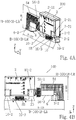
- FIG. 4A first shows the inventive evaporator unit 100 in a parallel perspective view.
- Figures 4B Segment view
- 4C top view
- 4D front view from the left
- 4E front view from the right
- the width B-100 of the evaporator unit 100 is smaller than 250 mm (B-100 ⁇ B-LR), whereby the evaporator unit 100 can be arranged without problems between the side supports LR-ST of the available installation space within that honeycomb lantern LR whose width is Internal dimension B-LR ⁇ 250 mm.
- the height H-100 of the evaporator unit 100 is smaller than the internal dimension between a top carrier LR-OT and a sub-carrier LR-UT of hitherto conventional honeycomb lanterns LR of different types of honeycomb lanterns LR according to the different types of bee bees.
- the height H-100 of the evaporator unit 100 is according to the invention smaller than 200 mm (H-100 ⁇ H-LR), whereby the evaporator unit 100 easily between the top carrier LR-OT and the sub-carrier LR-UT of the available space within those honeycomb latrines LR can be arranged, the height inside dimension H-LR is ⁇ 200.
- the depth T-100 of the evaporator unit 100 is smaller than the dimension of a carrier (carrier width) of a conventional honeycomb lantern LR of different types of honeycomb lanterns LR according to the different types of bees.
- the carrier width T-LR of the carriers LR-ST, LR-OT, LR-UT of various conventional honeycomb liners LR varies only insignificantly and is between 20 to 35 mm, so that the carrier width T-LR is at least 20 mm and a maximum of 35 mm.
- the depth T-100 of the evaporator unit 100 is according to the invention 38 mm (T-100> T-LR), whereby the evaporator unit 100 in dependence on the beam width T-LR conventional honeycomb lantern LR in the available space of the honeycomb LR with one compared to the different Depths of conventional honeycomb larms LR small supernatant between 3 and 18 mm is arranged.
- the supernatant is so small in a symmetrical arrangement of the evaporator unit 100 on the sub-carrier LR-UT of the conventional honeycomb LR that the bilateral projection is a maximum of between 1.5 mm and 9 mm.
- honeycomb lane between the honeycomb frames free space
- the optimal distance referred to as the honeycomb lane
- the evaporator unit 100 is dimensioned such that it can be arranged with a slight projection in a construction space which is predetermined by the respective dimensions H-LR x B-LR x T-LR of the respective conventional honeycomb latrines LR of the different types of loins, whereby the Evaporator unit 100 can be used advantageously in all conventional honeycomb latrines LR.
- the width B-100 of the evaporator unit 100 is according to the invention smaller than 350 mm (B-100 ⁇ B-LR), whereby the evaporator unit 100 easily between the side beams LR-ST '; LR-ST "of the available space of the respective standard honeycomb LR 'LR' can be arranged.
- the height H-100 of the evaporator unit 100 is inventively smaller than the internal dimension between an upper carrier LR-OT '; LR-OT "and a subcarrier LR-UT '; LR-UT" of one of the standard honeycomb lanterns LR' according to the invention; LR ".
- the internal dimension between the top carrier LR-OT '; LR-OT "and the sub-carrier LR-UT '; LR-UT" of the respective standard honeycomb carrier LR'; LR "is H-LR 200 mm
- the height H-100 of the evaporator unit 100 is smaller than 200 mm (H-100 ⁇ H-LR) according to the invention, whereby the evaporator unit 100 easily between the top carrier LR-OT ', LR-OT "and the subcarrier LR-UT '; LR-UT "of the available installation space of the respective standard honeycomb larms LR '; LR" can be arranged.
- the depth T-100 of the evaporator unit 100 is smaller than the dimension T-LR of a carrier LR-OT ', LR-UT', LR-ST '; LR-OT ", LR-UT", LR-ST "of the respective standard honeycomb larms LR '; LR".
- the depth T-100 of the evaporator unit 100 is 38 mm and the depth T-LR (beam width) of the respective standard honeycomb blanket LR '; LR "is according to the invention 40 mm (T-100 ⁇ T-LR), whereby the evaporator unit 100 in the standard honeycomb LR '; LR' in the available space of the standard honeycomb LR '; LR "can be arranged without projection.
- the evaporator unit 100 is dimensioned such that it with a small projection in a space of a conventional honeycomb LR and without supernatant in a space of a standard honeycomb LR '; LR "can be arranged, whereby the evaporator unit 100 can be used universally in an advantageous manner.
- the evaporator unit 100 comprises a reservoir 2 different from the prior art, a base 6-2 differing from the prior art as part of the new screw-on unit 6 and a fastening element 10 which is not present in the state of the art. which for fixing the evaporator unit 100 in the respective standard honeycomb LR '; LR "or the conventional honeycomb LR serves.
- the wick card holder S4 and wick card S8 are advantageously usable in the conventional evaporator unit S100 "Nassenheider professional" and in the conventional evaporator units “Nassenheider classic” and “Nassenheider horizontal” and the evaporator unit 100 according to the invention.
- the fastening element 10 represents in particular an element of the evaporator unit 100 according to the invention, which is not present in the conventional evaporator units "Nassenheider professional" and “Nassenheider classic” and “Nassenheider horizontal”.
- the fastening element 10 is designed according to the invention as a rail.
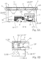
- the rail 10 is in FIG. 5A in a parallel perspective view obliquely from above and in FIG. 5B shown in a plan view.
- the rail 10 is a base support 10-1 (see FIG. 5A ), of which at least one in the preferred embodiment, two holding means 10-2 orthogonal to the base support 10-1 of the rail 10 depart, which are formed as a clasp-like receiving shoes.
- the Shoe 10-2 (compare FIG. 5A ) each comprise two oppositely extending walls in the Z direction, on the inner sides of each of which a locking means 10-21 is arranged, which are formed in the illustrated embodiment as extending in the X direction locking webs.
- the bottle 2 has (see FIG. 4A ) in the assembled state on their directed to the rail 10 side - starting from the cuboid lateral surface of the bottle 2 - four inwardly parked recesses 2-2.
- the recesses 2-2 correspond with regard to their negative contour with the positive contour of the walls of the receiving shoes 10-2, whereby the receiving shoes 10-2 can accommodate the bottle 2 in the form of a recess in the region of the recesses 2-2 in the assembled state.
- the walls of the pick-up shoes 10-2 are elastic and are easily spread when the bottle 2 is inserted into the pick-up shoes 10-2.
- the recesses 2-2 also form on the side opposite the base support 10-1 side groove-like in the X direction extending recesses 2-21, which in the FIGS. 4A and 4E are recognizable.
- the locking webs 10-21 engage in the groove-like recesses 2-21, whereby a positive stationary fixation of the bottle 2 in the rail 10 takes place.
- the slightly spread out during insertion of the bottle 2 walls of the receiving shoes 10-2 return by their elasticity by itself to its original position as soon as the locking webs 10-21 reversibly engage in the groove-like depressions 2-21, thereby always the fixed desired position of the bottle 2 is guaranteed.
- the rail 10 for accommodating the lid S5 of the novel bottle 2 has a lid receptacle 10-3, which (see FIGS. 4A and 5B ) is arranged in the assembled state of the evaporator unit 100 in the honeycomb LR on the upper side of the rail 10.
- the inner contour of the formed as a circumferential web edge lid receptacle 10-3 corresponds to the outer contour of the lid S5.
- the rail 10 as a further technical feature already at least one opening 10-4, which is also formed to its reinforcement with a circumferential web edge. In the at least one opening 10-4 is under specification of the attachment point / s (see FIG.
- a fastening member in particular a screw can be used, which is screwed into the lying below the rail 10 carrier, in particular the sub-carrier LR-UT of the honeycomb blank LR.
- the evaporator unit 100 is reversibly connected in the assembled state with a honeycomb LR.
- the rail 10 of the evaporator unit 100 (without the inserted bottle 2) can be mounted very easily and quickly in the honeycomb frame LR via the at least one fastening member. After mounting the rail 10, the assembly of the evaporator unit 100 in the honeycomb frame LR is performed as follows.
- This use of the evaporator unit 100 according to the invention is provided, provided that no evaporation nonwoven S9 is used to influence the evaporation performance.
- the procedure for using an evaporation nonwoven S9 will be explained.
- the evaporator unit 100 is part of modular evaporator systems, which According to the invention, the evaporator unit 100 and one of the standard honeycomb larms LR ', LR "or the evaporator unit and a conventional honeycomb larms LR comprise, which is tailored to the needs of working with different types of beet beekeeper and which are used in combination with the evaporator unit 100 are used could also be explained in detail below.
- LR ' Explained, which comprises standard multi-part honeycomb larms LR' and the inventive evaporator unit 100.
- the evaporator unit 100 of the evaporator system V is according to the FIGS. 4A to 5B shown in a parallel perspective view obliquely from above, the view according to the FIG. 6A (compare also FIGS. 7A and 8A ) in the position of use of the standard honeycomb liner LR 'in the hive BB, which faces away from the bees.
- FIG. 6B shows the standard honeycomb LR 'according to FIG. 6A with an enlarged detail of a connection point between an upper carrier LR-OT 'and a side carrier LR-ST' of the honeycomb carrier LR '.
- the standard evaporator system V comprises a standard consisting of four individual carriers LR-OT ', LR-UT' and LR-ST ', LR-ST' standard honeycomb lantern LR ', which are advantageously connected to each other at connection points easily connectable, wherein the individual carriers LR-OT ', LR-UT' and LR-ST ', LR-ST' have specific provisions that are compatible with the evaporator unit 100 and / or a protective element, in particular a protective gauze 11 or a protective grid, not shown, and / or one Ensure evaporation fleece S9.
- some individual carriers in particular the top carrier LR-OT 'and the side carrier LR-ST', LR-ST 'are designed such that an arrangement of the standard honeycomb LR' of the inventive standard evaporator system V, LR 'in a further advantageous manner in Difference to the previous honeycomb lantern LR from the prior art in different types of loot is possible, as explained below.
- FIG. 7A a parallel perspective view obliquely from below on the in the position of use of the standard honeycomb larmel LR 'in a hive BB facing away from the bees side, wherein the evaporator unit 100 is not yet fully assembled.
- FIG. 7B shows the standard evaporator system V, LR 'according to FIGS. 6A and 7A in a parallel perspective view from its back.
- the standard honeycomb frame LR ' has the top carrier LR-OT' and a sub-carrier LR-UT 'as well as the two side carriers LR-ST', which are preferably connectable to the standard honeycomb frame LR 'via latching connections.
- the two side support LR-ST 'end locking lugs a which in end-side locking receptacles b of the upper carrier LR-OT' and the subcarrier LR-UT 'can be latched, so that the single carrier LR-OT', LR-UT 'and the Side carrier LR-ST ', LR-ST' can be locked or clipped to the standard honeycomb carrier LR '.
- the upper carrier LR-OT 'furthermore has noses c, so-called longitudinal noses, which are each seen at the end in the longitudinal direction X and extend the upper carrier LR-OT' on both sides by a predefinable nose length.
- the standard honeycomb larms LR 'by means of the underside of the lugs c in a longitudinal direction X of the supporter LR-OT' most common type of boot on it the total length of the length (outer dimension 370 mm) of the top carrier LR-OT 'and the overlength of the longitudinal projections c (for example, each 10 mm) on the spacing width of the support elements of the currently most common Beekeeper type "German-Normal" is tuned.
- At least one longitudinal nose c is provided with an excess length which can be shortened to a desired dimension.
- the longitudinal nose c with the shortenable excess length can be matched to the contact width of the support elements of the most common types of honeybees "Dadant" or "Zander” or "Langstroth” or "German-normal” by the longitudinal nose c with the shortenable excess length is cut off.
- the side support LR-ST ' also each one end and on both sides seen transversely to the longitudinal direction X noses d, so-called cross noses, which widen the depth T (beam width) of the side support LR-ST' on both sides in the Y direction.
- the side beams LR-ST ' four transverse lugs d on.
- the undersides of the transverse lugs d can Advantageously in the X-direction seen wider common Beutentypen be suspended over the undersides of the transverse lugs d so that the standard Habenleerrähmchen LR 'with one side by means of two transverse lugs d - seen in the Y direction - on a boot wall of the respective Bee hive BB and the other side by means of the two opposite transverse lugs d - also seen in the Y direction - rests on an adjacent Habenrähmchen R or an adjacent Wabenleerrähmchen LR.
- a protective element in particular a protective gauze 11 or a protective grid (not shown) and / or the evaporation nonwoven S9 in the standard evaporator system V, LR 'can be integrated.
- the multi-part standard honeycomb larms LR 'and thus the standard evaporator system V, LR' includes other technical features, in particular arrangements for mounting the evaporation fabric S9 and the protective gauze 11 between the top carrier LR-OT 'and sub-carrier LR-UT'. In principle, these other technical features can also be used in the case of a one-piece standard honeycomb lantern LR ".
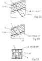
- FIGS. 6A and 6B , the Figures 8A and 8B as well as the Figures 9A and 9B show a first embodiment of a fastening means for attaching the flexible protective gauze 11 and the flexible evaporation nonwoven fabric S9 on the side facing away from the bee of the standard honeycomb LR 'in the open position I and in the closed position II of the fastener.
- the flexible protective gauze 11 and the evaporation non-woven fabric S9 are in the open position I of all folding clamping bars f initially applied peripherally on the underside of the subcarrier LR-UT 'area, after which all folding clamping webs f of the subcarrier LR-UT' are brought into the closed position II.
- the top carrier LR-OT 'and the sub-carrier LR-UT' are preferably U-shaped, so that in the opposite legs of the "U" on one side a hinge and opposite a latching device e can be formed, consisting of a clamping slot and / or a latching lug a is formed as in the FIGS. 9A, 9B is shown schematically.
- FIG. 9A shows the open position I of a folding clamping bar f and the FIG. 9B the closed position II of the folding-clamping web f and the hinge and the opposite locking device e, formed from the detent a and the clamping slot.
- At least one fixing element h which is arranged on the lower side of the subcarrier LR-UT ', preferably also serves for prefixing the protective gauze 11 and the evaporation nonwoven material S9.
- a fixing element h is preferably associated with at least each folding clamping web f, which engages in the closing position II of the folding clamping web f the folding clamping web f, as in FIG. 9B is shown.
- the protective gauze 11 and the evaporation nonwoven material S9 can simply be prefixed on the underside of the subcarrier LR-UT 'by piercing the edge material on the tips of the fixing elements h. Subsequently, the folding clamping webs f are brought into the closed position II, after which the flexible protective gauze 11 and the flexible evaporation non-woven fabric S9 is at least once wrapped around the sub-carrier LR-UT '.
- the protective gauze 11 and the evaporation nonwoven fabric S9 is clamped on the back of the standard honeycomb liner LR 'and prefixed with open folding clamping webs f analogously to the previously described procedure on at least one fixing element h preferably a plurality of fixing elements h, s / s on the top of the top carrier LR-OT 'of the standard honeycomb carrier LR' is / are arranged.
- each folding clamp web f is assigned a fixing element h there. Thereafter, the arranged on the top of the upper carrier LR-OT 'folding clamping webs f are brought into the closed position II, as FIG. 9B clarified.
- the protective gauze 11 and the evaporation nonwoven fabric S9 is prefixed and fixed to the upper support LR-OT 'and the lower support LR-UT' and on the upper side of the subcarrier LR-UT 'is arranged by the wrapping as the uppermost layer of the evaporation nonwoven fabric S9 impinging formic acid is taken up in a known manner from the evaporation nonwoven material S9 and released again by the temperature-dependent evaporation.
- the dimensions of the flexible protective gauze 11 are selected such that the protective gauze 11 completely covers the standard honeycomb blanket LR 'on the side facing the bees in the clamped assembled state.
- the protective gauze 11 can be wrapped around the sub-carrier LR-UT ', the side support LR-ST' recesses i, which allow the wrapping of the protective gauze 11 such that the protective gauze 11 in the assembled state, the standard honeycomb LR 'on the Completely covering bees facing side.
- the evaporator unit 100 Only after the arrangement of the protective gauze 11 and the evaporation nonwoven fabric S9, the evaporator unit 100 is mounted, as will be explained.
- the protective gauze 11 and the evaporation nonwoven fabric S9 in an optional embodiment edge and / or partial surface or entire surface by welding, gluing or mechanically or non-positively assembled.
- the evaporation nonwoven fabric S9 and the protective gauze as a protective element 11 have components that make it possible to establish a connection between the components by thermal action.
- the protective element 11, in particular the protective gauze can thus be connected to the evaporation web S9 and / or to the standard honeycomb blanket LR '.
- the selected joint connection results in a one-piece flexible component 11 / S9 of protective gauze 11 and evaporation nonwoven material S9, which can be attached more comfortably, since the components can not slip relative to one another.
- FIG. 10 shows in addition a second embodiment of a fastening means for attaching the protective gauze 11 and the evaporation nonwoven fabric S9 on the side facing away from the bees on the standard honeycomb LR 'in the fixing position of the protective gauze 11 and the evaporation nonwoven fabric S9 by the fastening means.
- the fastening means is a clamping piece g which is not connected to the standard honeycomb frame LR 'and is located on the underside of the sub-carrier LR-UT' and / or the upper side of the top carrier LR-OT 'between the two opposite legs of the "U" is clamped.
- the clamping piece g engages in the assembled state behind the locking lug of the locking device e and in the clamping slot.
- the clamping piece g is preferably cross-shaped, resulting in opposite end surfaces, which abut in the assembled state on the inner surfaces of the legs fit.
- formed in the position of use of the clamping piece g on the protective gauze 11 and / or the evaporation nonwoven S9 a large contact surface, which allows comfortable positioning and / or fixing the protective gauze 11 and the evaporation nonwoven S9.
- the cross-shaped shape causes a pleasant handling.
- the clamping piece g namely hollow inside and thus resiliently designed so that it can be easily clamped.
- fastening means f, g can be used alone or in combination, wherein the fixing elements h can additionally be used in any of the possible combinations.
- the protective element is not a flexible protective gauze, but a fixed non-flexible protective grid.
- the protective grid is arranged independently of the evaporation fleece or together with the evaporation fleece on the standard honeycomb larms LR '.
- the evaporation fleece S9 is fastened as described above and the protective grid is fixed separately on the side facing the bees, for which purpose corresponding fixing means (not shown) are provided on this side of the standard honeycomb frame LR '.
- the protective grid and the evaporation nonwoven fabric S9 are assembled over part of the surface or, in particular, welded, wherein the evaporation nonwoven fabric S9 forms an upper and lower edge, an attachment of the with the protective grid connected evaporation nonwoven S9 allowed.
- the lower edge is longer than the upper edge, so that the evaporation fleece S9 can be wound around the bottom edge around the sub-carrier LR-UT 'and the upper edge can be placed around the top carrier LR-OT'.
- the dimensions of the protective grid are selected so that the protective gauze 11 in the clamped assembly state, the standard honeycomb LR 'completely covering on the bees side facing.
- This positioning web 12 engages in a U-shaped positioning receptacle 10-5, which is formed between the walls of the receiving shoe 10-2 of the rail 10.
- the inner contour of the positioning receptacle 10-5 is directed in the assembled state to the positioning web 12 and has the outer contour of the positioning web 12, whereby the evaporator unit 100 can be positioned in the assembled state in two spatial directions, namely in the X direction and in the Y direction.
- the third spatial direction z corresponds to the height of the positioning web 12 and the positioning receptacle 10-5 relative to the upper side of the sub-carrier LR-UT ', which are also adapted accordingly, whereby in the assembled state a clear position fixation of the rail against the side support LR-ST' and the sub-carrier LR-UT 'is achieved.
- At least two fixing elements h for fixing the protective gauze 11 and / or the evaporation non-woven fabric S9 are also located on the upper side of the sub-carrier LR-UT 'at a distance in the Y direction (transverse to the longitudinal extension of the sub-carrier LR-UT') arranged that in the designated distance between the fixing elements h, the rail 10 is inserted, resulting in a further possibility for positioning of the rail 10 of the evaporator unit 100 results in the assembly and in the assembly state also a fixation of the protective gauze 11 and / or the evaporation fleece S9 on top of the subcarrier LR-UT 'causes.
- the protective gauze 11 and / or the evaporation fleece S9 are also located on the upper side of the sub-carrier LR-UT 'at a distance in the Y direction (transverse to the longitudinal extension of the sub-carrier LR-UT') arranged that in the designated distance between the fixing elements h, the rail 10 is inserted,
- the fixing elements h can be arranged on the outside of the rail and / or on the inside of the rail 10 in order to effect a clear positioning of the rail 10 of the evaporator unit 100 on the upper side of the subcarrier LR-UT '.
- an accurately fitting attachment is advantageously assuming the appropriate positioning of the rail 10, in particular by screwing fasteners through the openings 10-4 in the rail 10 possible, in which in the sub-carrier LR-UT 'advantageously provided openings 13 (see Figure 8A ) are assigned at the same location.
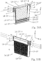
- FIGS. 13 to 14B is in particular on the similarities and differences of the second standard evaporator system V; LR "compared to the already explained in detail first standard evaporator system V, LR 'received.
- the second standard evaporator system V, LR “comprises the evaporator unit 100 and as a significant difference to the first standard evaporator system V-LR 'a standard one-piece honeycomb larms LR".
- FIG. 13 shows the one-piece standard honeycomb LR "and the evaporator unit 100 in the assembled state in a parallel perspective view obliquely from above.
- the one-piece standard honeycomb carrier LR also includes at least one top carrier LR-OT” and one sub-carrier LR-UT “as well as two side carriers LR-ST”.
- a lattice-like, hermetic protective element 11 is integrally formed on a rear side of the standard one-piece honeycomb lame frame L.
- the evaporation fleece S9 is subsequently applied to the manufacturer in advance.
- a lattice-like strut (not shown) stabilizing the standard honeycomb liner LR "is preferably formed on a rear side of the standard honeycomb liner LR". Only subsequently is a bee-impermeable protective element 11 attached to the lattice-like strut and / or the one-piece standard honeycomb larms LR ", which preferably has previously been connected to the evaporation fleece S9, in particular welded.
- the top carrier LR-OT is "hinged on a not-shown film hinge on the side members LR-ST", whereby the top carrier LR-OT "about a folding axis X1 from an open position I in a closed position II can be brought and connected in the closed position II with the side supports LR-ST ", in particular can be latched.
- FIGS. 13 to 14B illustrates that the one-piece standard honeycomb larms LR "two side support LR-ST", which are arranged obliquely relative to the top carrier LR-OT "and the sub-carrier LR-UT".
- a first distance between the side supports LR-ST "in the area of the top carrier LR-OT” is slightly larger than a second distance in the region of the sub-carrier LR-UT ", whereby a plurality of standard one-piece honeycomb frames LR", as explained above, in its open position I arranged upper carrier LR-OT "are stackable.
- the evaporator unit 100 comes, as also by the FIGS. 13 to 14B becomes clear, unchanged and can, as to the first standard evaporator system V; LR 'explained, are mounted on top of the subcarrier LR-UT ", with the already described to the first standard evaporator system V, LR' with respect to the arrangement of the evaporator unit 100 on the subcarrier LR-UT" in the FIGS. 13 to 14B not shown again.
- the stackability of the one-piece standard honeycomb larm "LR" in the parallel perspective front view according to 14A (with not yet mounted evaporator unit 100) obliquely from above on the nested standard honeycomb LR "clear, with the top carrier LR-OT" already around the folding axis X1 is moved to the closed position II
- the upper carrier LR-OT "of the other one-piece standard honeycomb larms LR” are in terms of not folded around the film hinge upper carrier LR-OT "in the open position I, which together with the oblique configuration of the side support LR- ST "the stackability of the standard honeycomb larms LR" is effected.
- Figure 14B shows the back of the second standard evaporator system V, LR "to illustrate the stackability of the invention one-piece standard honeycomb frame LR" in a parallel perspective rear view obliquely from above.
- the evaporation nonwoven material S9 is joined in optional embodiments on the edge and / or part of the surface or the entire surface by welding, gluing or mechanically or non-positively with the lattice-like bienenun to enter protective element 11.
- the evaporation nonwoven fabric S9 and the protective element 11 have components that allow to establish a connection between the components by thermal action.
- the one-piece standard honeycomb larm "LR" has the advantage that it is provided by the user no longer needs to be assembled. Due to the stackability, a space-saving shipping of several one-piece standard honeycomb frames LR "is possible analogously to the multi-part standard honeycomb larms LR '.
Landscapes
- Life Sciences & Earth Sciences (AREA)
- Environmental Sciences (AREA)
- Pest Control & Pesticides (AREA)
- General Health & Medical Sciences (AREA)
- Biodiversity & Conservation Biology (AREA)
- Health & Medical Sciences (AREA)
- Animal Husbandry (AREA)
- Toxicology (AREA)
- Engineering & Computer Science (AREA)
- Insects & Arthropods (AREA)
- Wood Science & Technology (AREA)
- Zoology (AREA)
- Catching Or Destruction (AREA)
Applications Claiming Priority (1)
| Application Number | Priority Date | Filing Date | Title |
|---|---|---|---|
| DE102017103338.6A DE102017103338B3 (de) | 2017-02-17 | 2017-02-17 | Verdunstersysteme, umfassend eine Verdunstereinheit für Ameisensäure und ein an die Verdunstereinheit angepasstes Standard-Wabenleerrähmchen |
Publications (2)
| Publication Number | Publication Date |
|---|---|
| EP3363286A2 true EP3363286A2 (fr) | 2018-08-22 |
| EP3363286A3 EP3363286A3 (fr) | 2018-12-19 |
Family
ID=61557015
Family Applications (1)
| Application Number | Title | Priority Date | Filing Date |
|---|---|---|---|
| EP18156688.6A Pending EP3363286A3 (fr) | 2017-02-17 | 2018-02-14 | Système d'évaporateur, comportant une unité d'évaporateur pour l'acide formique et un cadre vide standard adapté à l'unité d'évaporateur |
Country Status (2)
| Country | Link |
|---|---|
| EP (1) | EP3363286A3 (fr) |
| DE (1) | DE102017103338B3 (fr) |
Families Citing this family (1)
| Publication number | Priority date | Publication date | Assignee | Title |
|---|---|---|---|---|
| US12582100B2 (en) | 2019-12-09 | 2026-03-24 | Famlee Fund Gmbh | Dispenser for formic acid vapour and method for mite control in beehives |
Family Cites Families (15)
| Publication number | Priority date | Publication date | Assignee | Title |
|---|---|---|---|---|
| FR909069A (fr) * | 1945-02-06 | 1946-04-29 | Bâtisses de ruche en métal ou matière plastique | |
| FR1059791A (fr) * | 1951-11-23 | 1954-03-29 | Ruche à cadres | |
| AT345031B (de) * | 1975-07-09 | 1978-08-25 | Schade Franz Kg | Wabenrahmen fuer bienenstoecke |
| DE2654206A1 (de) | 1976-11-30 | 1978-06-01 | Matthias Schmidt | Wabenrahmen fuer mittelwaende |
| GB2270454B (en) * | 1992-09-02 | 1996-07-17 | Richard Phillips Alabone | Beehive frames |
| DE4236174A1 (de) * | 1992-10-27 | 1994-04-28 | Matthias Schmidt | Verfahren und Vorrichtung zum Ausschalten der Varroa-Milben |
| DE19610649A1 (de) | 1996-03-06 | 1996-09-12 | Bruno Becker | Vorrichtung zum kontinuierlichen Verdunsten von Flüssigkeiten, insbesondere Ameisensäure |
| WO1997032470A1 (fr) * | 1996-03-06 | 1997-09-12 | Weiland, Joachim | Procede et dispositif pour l'evaporation de liquides, notamment de l'acide formique |
| DE19645300A1 (de) | 1996-03-06 | 1998-04-30 | Bruno Becker | Vorrichtung zum kontinuierlichen Verdunsten von Flüssigkeiten, insbesondere Ameisensäure |
| DE19636498A1 (de) * | 1996-09-09 | 1998-03-12 | Wilhelm Buschack | Applikator-Verdunstungsgerät Einrichtung zum Verdunsten von Flüssigkeiten, Säuren, Alkohol u. a., für die Behandlung von Bienenvölkern |
| DE19943711A1 (de) | 1999-09-08 | 2001-03-15 | Bruno Becker | Vorrichtung zum kontinuierlichen Verdunsten von Flüssigkeiten, insbesondere Ameisensäure |
| US6620025B2 (en) * | 2001-04-12 | 2003-09-16 | Theodore W. Scheuneman | Evaporator for the treatment of honey bee diseases and undesirable hive conditions |
| DE10309323A1 (de) * | 2003-03-04 | 2004-09-16 | Wilhelm Buschack | Verdunstungs-Applikator zur Bekämpfung von Bienenkrankheiten |
| US8814630B2 (en) * | 2011-01-04 | 2014-08-26 | Carl T. Rittberger | PVC beehive |
| RU2558110C2 (ru) * | 2013-05-31 | 2015-07-27 | Владимир Николаевич Максимов | Модульный улей и модуль улья |
-
2017
- 2017-02-17 DE DE102017103338.6A patent/DE102017103338B3/de active Active
-
2018
- 2018-02-14 EP EP18156688.6A patent/EP3363286A3/fr active Pending
Also Published As
| Publication number | Publication date |
|---|---|
| EP3363286A3 (fr) | 2018-12-19 |
| DE102017103338B3 (de) | 2018-04-05 |
Similar Documents
| Publication | Publication Date | Title |
|---|---|---|
| CH694312A5 (de) | Käfig für verschiedene Nagerarten. | |
| DE3436489A1 (de) | Behaelter fuer endoskope und zubehoerteile | |
| DE102017103338B3 (de) | Verdunstersysteme, umfassend eine Verdunstereinheit für Ameisensäure und ein an die Verdunstereinheit angepasstes Standard-Wabenleerrähmchen | |
| DE60222017T2 (de) | Bienenkorbbasisvorrichtung | |
| DE8320334U1 (de) | Halterungsvorrichtung für einen aus thermoplastischem Kunststoff bestehenden Kraftstoffbehälter für Kraftfahrzeuge | |
| DE102013002579B4 (de) | Tankkombination in einem Nutzfahrzeug, insbesondere Lkw oder Omnibus | |
| DE202017100888U1 (de) | Verdunstersysteme, umfassend eine Verdunstereinheit für Ameisensäure und ein an die Verdunstereinheit angepasstes Standard-Wabenleerrähmchen | |
| DE102008042922B4 (de) | Zaunklammer zur Befestigung eines Zaungitters an einem Pfosten | |
| EP0959674B1 (fr) | Procede et dispositif pour l'evaporation de liquides, notamment de l'acide formique | |
| DE69709205T2 (de) | Feuchtigkeitsabsorbierendes Gerät | |
| DE2924629A1 (de) | Lockstoff-falle fuer fliegende forstschaedlinge, insbesondere borkenkaefer | |
| DE60013598T2 (de) | Filterdeckelanordnung für nagetierkäfig | |
| DE4026105C1 (en) | Carrier for plant culture troughs - has rails with sprung fish plates to retain troughs for plants | |
| EP2961261B1 (fr) | Dispositif d'irrigation de plantes | |
| EP3868260A1 (fr) | Dispositif de maintien des chalumeaux | |
| DE102021000043A1 (de) | Abstandsrechen zur Anordnung von Honigwaben-Rahmen in einer Zarge | |
| DE3225677C2 (de) | Pedal fuer einen fahrradartigen heimtrainer | |
| EP0474967A1 (fr) | Ski | |
| EP3974597A1 (fr) | Système de montage de toit, dispositif de montage de toit et procédé de construction d'un dispositif de montage de toit | |
| DE8616139U1 (de) | Sammelfalle für Varroa-Milben in Bienenstöcken | |
| DE69003707T2 (de) | Mehrzweckwandhalter für Behälter. | |
| EP3838797B1 (fr) | Contenant pour fleurs, ensemble pour monter un contenant pour fleurs | |
| AT16678U1 (de) | Halterung für Wirkstoffstreifen | |
| DE3433438C2 (fr) | ||
| EP0403888A1 (fr) | Véhicule pour substances actives pour ruches |
Legal Events
| Date | Code | Title | Description |
|---|---|---|---|
| PUAI | Public reference made under article 153(3) epc to a published international application that has entered the european phase |
Free format text: ORIGINAL CODE: 0009012 |
|
| STAA | Information on the status of an ep patent application or granted ep patent |
Free format text: STATUS: THE APPLICATION HAS BEEN PUBLISHED |
|
| AK | Designated contracting states |
Kind code of ref document: A2 Designated state(s): AL AT BE BG CH CY CZ DE DK EE ES FI FR GB GR HR HU IE IS IT LI LT LU LV MC MK MT NL NO PL PT RO RS SE SI SK SM TR |
|
| AX | Request for extension of the european patent |
Extension state: BA ME |
|
| PUAL | Search report despatched |
Free format text: ORIGINAL CODE: 0009013 |
|
| AK | Designated contracting states |
Kind code of ref document: A3 Designated state(s): AL AT BE BG CH CY CZ DE DK EE ES FI FR GB GR HR HU IE IS IT LI LT LU LV MC MK MT NL NO PL PT RO RS SE SI SK SM TR |
|
| AX | Request for extension of the european patent |
Extension state: BA ME |
|
| RIC1 | Information provided on ipc code assigned before grant |
Ipc: A01K 47/02 20060101ALI20181109BHEP Ipc: A01M 13/00 20060101ALI20181109BHEP Ipc: A01K 51/00 20060101AFI20181109BHEP Ipc: A01M 1/00 20060101ALI20181109BHEP |
|
| STAA | Information on the status of an ep patent application or granted ep patent |
Free format text: STATUS: REQUEST FOR EXAMINATION WAS MADE |
|
| 17P | Request for examination filed |
Effective date: 20190321 |
|
| RBV | Designated contracting states (corrected) |
Designated state(s): AL AT BE BG CH CY CZ DE DK EE ES FI FR GB GR HR HU IE IS IT LI LT LU LV MC MK MT NL NO PL PT RO RS SE SI SK SM TR |
|
| STAA | Information on the status of an ep patent application or granted ep patent |
Free format text: STATUS: EXAMINATION IS IN PROGRESS |
|
| 17Q | First examination report despatched |
Effective date: 20191001 |
|
| REG | Reference to a national code |
Ref country code: DE Ref legal event code: R079 Free format text: PREVIOUS MAIN CLASS: A01K0051000000 Ipc: A01M0001200000 |
|
| RIC1 | Information provided on ipc code assigned before grant |
Ipc: A01M 1/20 20060101AFI20251118BHEP Ipc: A01K 51/00 20060101ALI20251118BHEP Ipc: A01K 47/02 20060101ALI20251118BHEP Ipc: A01M 13/00 20060101ALI20251118BHEP |
|
| GRAP | Despatch of communication of intention to grant a patent |
Free format text: ORIGINAL CODE: EPIDOSNIGR1 |
|
| STAA | Information on the status of an ep patent application or granted ep patent |
Free format text: STATUS: GRANT OF PATENT IS INTENDED |
|
| INTG | Intention to grant announced |
Effective date: 20260204 |