EP3364125B1 - Erwärmungsvorrichtung mit einer wärmepumpe - Google Patents
Erwärmungsvorrichtung mit einer wärmepumpe Download PDFInfo
- Publication number
- EP3364125B1 EP3364125B1 EP16855560.5A EP16855560A EP3364125B1 EP 3364125 B1 EP3364125 B1 EP 3364125B1 EP 16855560 A EP16855560 A EP 16855560A EP 3364125 B1 EP3364125 B1 EP 3364125B1
- Authority
- EP
- European Patent Office
- Prior art keywords
- heat exchanger
- compressor
- hot water
- heating
- temperature
- Prior art date
- Legal status (The legal status is an assumption and is not a legal conclusion. Google has not performed a legal analysis and makes no representation as to the accuracy of the status listed.)
- Active
Links
Images


Classifications
-
- F—MECHANICAL ENGINEERING; LIGHTING; HEATING; WEAPONS; BLASTING
- F25—REFRIGERATION OR COOLING; COMBINED HEATING AND REFRIGERATION SYSTEMS; HEAT PUMP SYSTEMS; MANUFACTURE OR STORAGE OF ICE; LIQUEFACTION SOLIDIFICATION OF GASES
- F25B—REFRIGERATION MACHINES, PLANTS OR SYSTEMS; COMBINED HEATING AND REFRIGERATION SYSTEMS; HEAT PUMP SYSTEMS
- F25B30/00—Heat pumps
- F25B30/02—Heat pumps of the compression type
-
- F—MECHANICAL ENGINEERING; LIGHTING; HEATING; WEAPONS; BLASTING
- F24—HEATING; RANGES; VENTILATING
- F24F—AIR-CONDITIONING; AIR-HUMIDIFICATION; VENTILATION; USE OF AIR CURRENTS FOR SCREENING
- F24F11/00—Control or safety arrangements
- F24F11/89—Arrangement or mounting of control or safety devices
-
- F—MECHANICAL ENGINEERING; LIGHTING; HEATING; WEAPONS; BLASTING
- F24—HEATING; RANGES; VENTILATING
- F24H—FLUID HEATERS, e.g. WATER OR AIR HEATERS, HAVING HEAT-GENERATING MEANS, e.g. HEAT PUMPS, IN GENERAL
- F24H4/00—Fluid heaters characterised by the use of heat pumps
- F24H4/02—Water heaters
-
- F—MECHANICAL ENGINEERING; LIGHTING; HEATING; WEAPONS; BLASTING
- F25—REFRIGERATION OR COOLING; COMBINED HEATING AND REFRIGERATION SYSTEMS; HEAT PUMP SYSTEMS; MANUFACTURE OR STORAGE OF ICE; LIQUEFACTION SOLIDIFICATION OF GASES
- F25B—REFRIGERATION MACHINES, PLANTS OR SYSTEMS; COMBINED HEATING AND REFRIGERATION SYSTEMS; HEAT PUMP SYSTEMS
- F25B1/00—Compression machines, plants or systems with non-reversible cycle
-
- F—MECHANICAL ENGINEERING; LIGHTING; HEATING; WEAPONS; BLASTING
- F25—REFRIGERATION OR COOLING; COMBINED HEATING AND REFRIGERATION SYSTEMS; HEAT PUMP SYSTEMS; MANUFACTURE OR STORAGE OF ICE; LIQUEFACTION SOLIDIFICATION OF GASES
- F25B—REFRIGERATION MACHINES, PLANTS OR SYSTEMS; COMBINED HEATING AND REFRIGERATION SYSTEMS; HEAT PUMP SYSTEMS
- F25B13/00—Compression machines, plants or systems, with reversible cycle
-
- F—MECHANICAL ENGINEERING; LIGHTING; HEATING; WEAPONS; BLASTING
- F25—REFRIGERATION OR COOLING; COMBINED HEATING AND REFRIGERATION SYSTEMS; HEAT PUMP SYSTEMS; MANUFACTURE OR STORAGE OF ICE; LIQUEFACTION SOLIDIFICATION OF GASES
- F25B—REFRIGERATION MACHINES, PLANTS OR SYSTEMS; COMBINED HEATING AND REFRIGERATION SYSTEMS; HEAT PUMP SYSTEMS
- F25B49/00—Arrangement or mounting of control or safety devices
- F25B49/02—Arrangement or mounting of control or safety devices for compression type machines, plants or systems
- F25B49/025—Motor control arrangements
-
- F—MECHANICAL ENGINEERING; LIGHTING; HEATING; WEAPONS; BLASTING
- F25—REFRIGERATION OR COOLING; COMBINED HEATING AND REFRIGERATION SYSTEMS; HEAT PUMP SYSTEMS; MANUFACTURE OR STORAGE OF ICE; LIQUEFACTION SOLIDIFICATION OF GASES
- F25B—REFRIGERATION MACHINES, PLANTS OR SYSTEMS; COMBINED HEATING AND REFRIGERATION SYSTEMS; HEAT PUMP SYSTEMS
- F25B2600/00—Control issues
- F25B2600/11—Fan speed control
- F25B2600/112—Fan speed control of evaporator fans
-
- F—MECHANICAL ENGINEERING; LIGHTING; HEATING; WEAPONS; BLASTING
- F25—REFRIGERATION OR COOLING; COMBINED HEATING AND REFRIGERATION SYSTEMS; HEAT PUMP SYSTEMS; MANUFACTURE OR STORAGE OF ICE; LIQUEFACTION SOLIDIFICATION OF GASES
- F25B—REFRIGERATION MACHINES, PLANTS OR SYSTEMS; COMBINED HEATING AND REFRIGERATION SYSTEMS; HEAT PUMP SYSTEMS
- F25B2700/00—Sensing or detecting of parameters; Sensors therefor
- F25B2700/21—Temperatures
- F25B2700/2103—Temperatures near a heat exchanger
-
- F—MECHANICAL ENGINEERING; LIGHTING; HEATING; WEAPONS; BLASTING
- F25—REFRIGERATION OR COOLING; COMBINED HEATING AND REFRIGERATION SYSTEMS; HEAT PUMP SYSTEMS; MANUFACTURE OR STORAGE OF ICE; LIQUEFACTION SOLIDIFICATION OF GASES
- F25B—REFRIGERATION MACHINES, PLANTS OR SYSTEMS; COMBINED HEATING AND REFRIGERATION SYSTEMS; HEAT PUMP SYSTEMS
- F25B2700/00—Sensing or detecting of parameters; Sensors therefor
- F25B2700/21—Temperatures
- F25B2700/2106—Temperatures of fresh outdoor air
-
- Y—GENERAL TAGGING OF NEW TECHNOLOGICAL DEVELOPMENTS; GENERAL TAGGING OF CROSS-SECTIONAL TECHNOLOGIES SPANNING OVER SEVERAL SECTIONS OF THE IPC; TECHNICAL SUBJECTS COVERED BY FORMER USPC CROSS-REFERENCE ART COLLECTIONS [XRACs] AND DIGESTS
- Y02—TECHNOLOGIES OR APPLICATIONS FOR MITIGATION OR ADAPTATION AGAINST CLIMATE CHANGE
- Y02B—CLIMATE CHANGE MITIGATION TECHNOLOGIES RELATED TO BUILDINGS, e.g. HOUSING, HOUSE APPLIANCES OR RELATED END-USER APPLICATIONS
- Y02B30/00—Energy efficient heating, ventilation or air conditioning [HVAC]
- Y02B30/12—Hot water central heating systems using heat pumps
Definitions
- the present invention relates to a heat pump-type heating device including members such as a heating-purpose heat exchanger and a method of operating a heat pump-type heating device.
- the heat pump unit includes a heating-purpose heat exchanger which is configured to heat the hot water flowing in the heating circuit.
- the heating-purpose heat exchanger the hot water flowing in the heating circuit is heated by a refrigerant discharged from a compressor of the heat pump unit.
- the present invention has been done to solve this problem, and an object of the invention is to provide a heat pump-type heating device in which lowering of the oil level in a compressor is prevented and a method of operating a heat pump-type heating device.
- a heat pump-type heating device includes : a refrigerant circuit in which a compressor, a heat-source-side heat exchanger, a motor-operated valve, and a target-side heat exchanger are provided; and an outdoor fan which is provided for the heat-source-side heat exchanger, the target-side heat exchanger being capable of heating, by a refrigerant, fluid supplied from outside, and a control unit characterized in that the control unit is configured to carry out a rotation number reduction control when a difference between a temperature of the fluid supplied to the target-side heat exchanger and an outside temperature is equal to or larger than a predetermined temperature difference, so that the rotation number of the outdoor fan upon activation of the compressor is smaller than when the difference is smaller than the predetermined temperature difference.
- the heat pump-type heating device of the first aspect is arranged such that the control unit (56) is configured to carry out the rotation number reduction control of reducing the rotation number of the outdoor fan upon activation of the compressor when a discharge temperature of the compressor is equal to or lower than a predetermined temperature.
- the rotation number reduction control is carried out only when the discharge temperature of the compressor is equal to or lower than the predetermined temperature. It is therefore possible to prevent the rotation number of the outdoor fan from being decreased when the refrigerant is not condensed in the dome of the compressor upon activation of the compressor.
- the heat pump-type heating device of the first or second aspect is arranged such that the control unit (56) is configured to terminate the rotation number reduction control of reducing the rotation number of the outdoor fan upon activation of the compressor when a discharge temperature of the compressor is higher than a temperature of the target-side heat exchanger.
- the rotation number reduction control can be terminated when the discharge temperature of the compressor becomes higher than the temperature of the target-side heat exchanger and the refrigerant is no longer condensed in the dome of the compressor.
- the heat pump-type heating device of any one of the first to third aspects is arranged such that the control unit (56) is configured to terminate the rotation number reduction control of reducing the rotation number of the outdoor fan upon activation of the compressor when a temperature of the heat-source-side heat exchanger is lower than the outside temperature.
- the rotation number reduction control can be terminated when the temperature of the heat-source-side heat exchanger becomes lower than the outside temperature and the refrigerant is no longer condensed in the dome of the compressor.
- the rotation number of the outdoor fan upon activation of the compressor is controlled to be small when the difference between the temperature of the fluid supplied to the target-side heat exchanger and the outside temperature is equal to or larger than the predetermined temperature difference, condensation of refrigerant in the dome of the compressor is restrained. It is therefore possible to prevent the oil level in the compressor from being lowered upon activation of the compressor.
- the rotation number reduction control is carried out only when the discharge temperature of the compressor is equal to or lower than the predetermined temperature. It is therefore possible to prevent the rotation number of the outdoor fan from being decreased when the refrigerant is not condensed in the dome of the compressor upon activation of the compressor.
- the rotation number reduction control can be terminated when the discharge temperature of the compressor becomes higher than the temperature of the target-side heat exchanger and the refrigerant is no longer condensed in the dome of the compressor.
- the rotation number reduction control can be terminated when the temperature of the heat-source-side heat exchanger becomes lower than the outside temperature and the refrigerant is no longer condensed in the dome of the compressor.
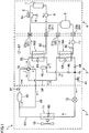
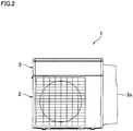
- a heat pump-type heating device (outdoor unit) 1 includes a heat pump unit 2 and a water unit 3 provided above the heat pump unit 2, as shown in FIG. 1 and FIG. 2 .
- the heat pump unit 2 houses a compressor 10, an outdoor heat exchanger (heat-source-side heat exchanger) 11, a motor-operated valve 12, and an outdoor fan 13.
- the water unit 3 houses a hot water supply heat exchanger (target-side heat exchanger) 16A, a heating-purpose heat exchanger (target-side heat exchanger) 16B, and a water supply pump 17.
- a refrigerant circuit (heat pump) in which a refrigerant circulates is constructed inside the outdoor unit 1.
- This refrigerant circuit includes a main passage 23, a first passage 24, a second passage 25, and a low-pressure passage 26.
- the compressor 10 the outdoor heat exchanger 11, and the motor-operated valve 12 are provided in order.
- a four-pass switching valve 18 is connected to the discharging end of the compressor 10 which is arranged on the passage connected to one end of the outdoor heat exchanger 11.
- the first passage 24 and the second passage 25 are branched from the four-pass switching valve 18 arranged on the passage connected to the discharging end of the compressor 10, and are merged at a merging point 19 which is on a passage connected to the other end of the outdoor heat exchanger 11. Between the merging point 19 and the motor-operated valve 12 on the main passage 23, a service port 41 is provided to communicate with the refrigerant circuit.
- the service port 41 is used for, for example, pouring a refrigerant into the refrigerant circuit from the outside at a maintenance time, or discharging the refrigerant from the refrigerant circuit to the outside.
- the first passage 24 connects the four-pass switching valve 18 provided downstream of the compressor 10 on the main passage 23 to the merging point 19 provided upstream of the motor-operated valve 12.
- the hot water supply heat exchanger 16A and a first check valve 44 are provided on the first passage 24.
- the first check valve 44 is provided between the hot water supply heat exchanger 16A and the merging point 19.
- the first check valve 44 allows the refrigerant to flow from the hot water supply heat exchanger 16A to the merging point 19 but prevents the refrigerant from flowing from the merging point 19 to the hot water supply heat exchanger 16A (first passage 24) .
- the second passage 25 connects the four-pass switching valve 18 and the merging point 19 to the first passage 24 in a parallel manner.
- the heating-purpose heat exchanger 16B, a receiver 46, and a second check valve 48 are provided on the second passage 25, the heating-purpose heat exchanger 16B, a receiver 46, and a second check valve 48 are provided.
- the second check valve 48 allows the refrigerant to flow from the heating-purpose heat exchanger 16B to the merging point 19 but prevents the refrigerant from flowing from the merging point 19 to the heating-purpose heat exchanger 16B (second passage 25) .
- the receiver 46 is a container storing the refrigerant, and is provided between the heating-purpose heat exchanger 16B and the second check valve 48 of the second passage 25 which is smaller in refrigerant capacity than the first passage 24.
- the second check valve 48 is provided between the heating-purpose heat exchanger 16B and the merging point 19 (i.e. , downstream of the heating-purpose heat exchanger 16B and upstream of the merging point 19).
- the low-pressure passage 26 connects the four-pass switching valve 18 to the sucking side of the compressor 10 . While the sucking side of the compressor 10 indicates a part between the motor-operated valve 12 and the compressor 10, the low-pressure passage 26 is specifically connected to a part between the compressor 10 and the outdoor heat exchanger 11.
- the water supply pump 17 supplies hot water for hot-water-supply (hereinafter, supply-purpose hot water) flowing out from a hot water supply tank 5 to the hot water supply heat exchanger 16A, and circulates the supply-purpose hot water to the hot water supply tank 5.
- supply-purpose hot water hot-water-supply
- the heat pump-type heating device 1 includes a discharge temperature sensor 61 configured to detect a discharge temperature of the compressor 10, a hot-water-supply inflow water temperature sensor 62 configured to detect an inflow water temperature of the hot water supply heat exchanger (target-side heat exchanger) 16A, a heating inflow water temperature sensor 63 configured to detect an inflow water temperature of the heating-purpose heat exchanger (target-side heat exchanger) 16B, a hot-water-supply heat-exchange temperature sensor 64 configured to detect a condensation temperature of the hot water supply heat exchanger (target-side heat exchanger) 16A, a heating heat-exchange temperature sensor 65 configured to detect a condensation temperature of the heating-purpose heat exchanger (target-side heat exchanger) 16B, an outdoor heat-exchange temperature sensor 66 configured to detect a temperature of the outdoor heat exchanger 11, and an outside temperature sensor 67 configured to detect the outside temperature.
- a discharge temperature sensor 61 configured to detect a discharge temperature of the compressor 10
- the above-described refrigerant circuit is switched between a first state and a second state which are described later by the four-pass switching valve 18 so that the refrigerant discharged from the compressor 10 flows in one of the first passage 24 and the second passage 25 and does not flow in the other one of them.
- the refrigerant discharged from the compressor 10 flows in the first passage 24 but does not flow in the second passage 25, and the second passage 25 is connected to the low pressure side of the main passage 23.
- a refrigerant inflow port of the first passage 24 is connected to the discharging end of the compressor 10 via the four-pass switching valve 18, and a refrigerant outflow port of the first passage 24 is connected to the motor-operated valve 12.
- One end of the second passage 25 in which the refrigerant does not flow is connected to the low-pressure passage 26 via the four-pass switching valve 18, whereas the other end is connected to the merging point 19.
- the refrigerant discharged from the compressor 10 flows into the first passage 24 via the four-pass switching valve 18.
- the refrigerant reaches the motor-operated valve 12 via the merging point 19.
- the refrigerant in the second passage 25 flows into the low-pressure passage 26 via the four-pass switching valve 18 and is sucked into the compressor 10.
- the refrigerant between the merging point 19 and the second check valve 48 is not sucked further into the compressor 10 on account of the presence of the second check valve 48.
- the refrigerant discharged from the compressor 10 flows in the second passage 25 and does not flow in the first passage 24, and the first passage 24 is connected to the low pressure side of the main passage 23.
- a refrigerant inflow port of the second passage 25 is connected to the discharging end of the compressor 10 via the four-pass switching valve 18, and a refrigerant outflow port of the second passage 25 is connected to the motor-operated valve 12.
- One end of the first passage 24 in which the refrigerant does not flow is connected to the low-pressure passage 26 via the four-pass switching valve 18, whereas the other end is connected to the merging point 19.
- the refrigerant discharged from the compressor 10 flows into the second passage 25 via the four-pass switching valve 18.
- the refrigerant reaches the motor-operated valve 12 via the merging point 19.
- the refrigerant in the first passage 24 flows into the low-pressure passage 26 via the four-pass switching valve 18 and is sucked into the compressor 10.
- the refrigerant between the merging point 19 and the first check valve 44 is not further sucked into the compressor 10 on account of the presence of the first check valve 44.
- the water unit 3 includes a hot water supply pipe connector 20 and a heating water supply pipe connector 21.
- the hot water supply pipe connector 20 includes a feed connector 20a and a return connector 20b
- the heating water supply pipe connector 21 includes a feed connector 21a and a return connector 21b.
- the feed connector 20a of the hot water supply pipe connector 20 is connected to a water outflow port of the hot water supply heat exchanger 16A, whereas the return connector 20b of the hot water supply pipe connector 20 is connected to a water inflow port of the hot water supply heat exchanger 16A.
- the hot water supply heat exchanger 16A, the hot water supply tank 5, and the hot water supply pump 17 are connected to one another, a hot water supply circuit is constructed.
- the feed connector 21a of the heating water supply pipe connector 21 is connected to a water outflow port of the heating-purpose heat exchanger 16B, whereas the return connector 21b of the heating water supply pipe connector 21 is connected to a water inflow port of the heating-purpose heat exchanger 16B.
- a gas boiler 6, a heating terminal 7, and a pump 8 are connected to one another, a heating circuit is constructed.
- the heating-purpose heat exchanger 16B On account of heat exchange at the heating-purpose heat exchanger 16B between the refrigerant flowing from the four-pass switching valve 18 on the passage connected to the discharging end of the compressor 10 and hot water for heating (hereinafter, heating-purpose hot water) flowing from the return connector 21b of the heating water supply pipe connector 21, the heating-purpose hot water is heated and the heated heating-purpose hot water flows out toward the feed connector 21a of the heating water supply pipe connector 21.
- the outdoor unit 1 is able to heat one of the supply-purpose hot water and the heating-purpose hot water.
- the heat pump-type heating device 1 of the present embodiment is connected to a target-side apparatus 4.
- the target-side apparatus 4 includes the hot water supply tank 5, the gas boiler 6, the heating terminal 7 such as a floor heating panel, and the pump
- the gas boiler 6 includes a heater 6a and is connected to the heating terminal 7 and a hot water supply terminal 9.
- the gas boiler 6 is therefore able to heat the supply-purpose hot water supplied from the hot water supply tank 5 before this water is supplied to the hot water supply terminal 9, and to heat the heating-purpose hot water supplied from the outdoor unit 1 before this water is supplied to the heating terminal 7.
- the pump 8 is configured to supply the heating-purpose hot water flowing out from the heating terminal 7 to the heating-purpose heat exchanger 16B and circulate the heating-purpose heat exchanger supplied to the heating terminal 7.
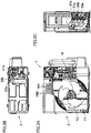
- FIG. 3A is a partially broken view illustrating the internal structure of the heat pump unit 2 and the water unit 3 when the outdoor unit 1 is viewed from the front.
- FIG. 3B is a partially broken view illustrating the internal structure of the water unit 3 when the outdoor unit 1 is viewed from above.
- FIG. 3C is a partially broken view illustrating the layout of the hot water supply pipe connector 20 and the heating water supply pipe connector 21 when the right side face of the outdoor unit 1 is viewed.
- the four-pass switching valve 18 is provided in the heat pump unit 2.
- FIG. 4A and FIG. 4B are a perspective view and a side view of the hot water supply heat exchanger 16A and the heating-purpose heat exchanger 16B. Inside the water unit 3 of the outdoor unit 1, the hot water supply heat exchanger 16A and the heating-purpose heat exchanger 16B are stacked on each other in the up-down direction as shown in FIG. 4A .
- the heating-purpose heat exchanger 16B includes the heating water pipe 32 which is wound to form two stages in the up-down direction, whereas the hot water supply heat exchanger 16A includes the hot water supply pipe 31 which is wound to form two stages in the up-down direction.
- each stage of the hot water supply pipe 31 and the heating water pipe 32 is wound in a substantially spiral manner.
- the water inflow port of the hot water supply heat exchanger 16A is connected to a hot water supply return connection pipe 31a which extends from the water supply pump 17 (the return connector 20b of the hot water supply pipe connector 20), whereas the water outflow port of the hot water supply heat exchanger 16A is connected to a hot water supply feed connection pipe 31b which extends from the feed connector 20a of the hot water supply pipe connector 20.
- the water inflow port of the heating-purpose heat exchanger 16B is connected to a heating return connection pipe 32a which extends from the return connector 21b of the heating water supply pipe connector 21, whereas the water outflow port of the heating-purpose heat exchanger 16B is connected to a heating feed connection pipe 32b which extends from the feed connector 21a of the heating water supply pipe connector 21.
- a hot water supply refrigerant pipe 33 is provided in a spiral manner on the outer circumference of a hot water supply pipe 31.
- a heating refrigerant pipe 34 is provided in a spiral manner on the outer circumference of a heating water pipe 32.
- the refrigerant inflow port of the hot water supply heat exchanger 16A is connected to a hot water supply connection pipe 33a which extends from a branching point 18 on the passage connected to the discharging end of the compressor 10, whereas the refrigerant outflow port of the hot water supply heat exchanger 16A is connected to a hot water supply connection pipe 33b which extends from the motor-operated valve 12.
- the refrigerant inflow port of the heating-purpose heat exchanger 16B is connected to a heating connection pipe 34a which extends from the branching point 18 on the passage connected to the discharging end of the compressor 10, whereas the refrigerant outflow port of the heating-purpose heat exchanger 16B is connected to a heating connection pipe 34b which extends from the motor-operated valve 12.
- the hot water supply heat exchanger 16A is a part where the hot water supply refrigerant pipe 33 is provided in a spiral manner on the outer circumference of a hot water supply pipe 31, whereas the heating-purpose heat exchanger 16B is a part where the heating refrigerant pipe 34 is provided in a spiral manner on the outer circumference of a heating water pipe 32.
- the hot water supply pipe 31 of the hot water supply heat exchanger 16A is wound to form two stages in the up-down direction, and is arranged in such a way that the supply-purpose hot water flows from the hot water supply return connection pipe 31a into a part of the pipe which is on the lower stage, and the supply-purpose hot water flows out from a part of the pipe which is on the upper stage to the hot water supply feed connection pipe 31b.
- the heating water pipe 32 of the heating-purpose heat exchanger 16B is wound to form two stages in the up-down direction, and is arranged in such a way that the heating-purpose hot water flows from the heating return connection pipe 32a into a part of the pipe which is on the lower stage, and the heating-purpose hot water flows out from a part of the pipe which is on the upper stage to the heating feed connection pipe 32b.
- the hot water supply pipe 31 of the hot water supply heat exchanger 16A and the heating water pipe 32 of the heating-purpose heat exchanger 16B, which are structured as above, are stacked on each other inside the water unit 3.
- the hot water supply heat exchanger 16A is wound to form two stages and the supply-purpose hot water flows out from a part of the pipe (i.e., the outer pipe) on the uppermost stage, whereas the heating-purpose heat exchanger 16B is stacked above the hot water supply heat exchanger 16A (i.e., the heating-purpose heat exchanger 16B is stacked on the hot water supply heat exchanger 16A to be close to the part of the pipe (i.e., the outer pipe) on the uppermost stage in the hot water supply pipe 31).
- the hot water supply heat exchanger 16A is connected to water connection pipes (the hot water supply return connection pipe 31a and the hot water supply feed connection pipe 31b) and refrigerant connection pipes (the hot water supply connection pipe 33a and the hot water supply connection pipe 33b), whereas the heating-purpose heat exchanger 16B is connected to water connection pipes (the heating return connection pipe 32a and the heating feed connection pipe 32b) and refrigerant connection pipes (the heating connection pipe 34a and the heating connection pipe 34b).
- a control unit 56 of the heat pump-type heating device 1 is connected to the compressor 10, the motor-operated valve 12, the outdoor fan 13, a controller 4a of the target-side apparatus 4, the discharge temperature sensor 61, the hot-water-supply inflow water temperature sensor 62, the heating inflow water temperature sensor 63, the hot-water-supply heat-exchange temperature sensor 64, the heating heat-exchange temperature sensor 65, the outdoor heat-exchange temperature sensor 66, and the outside temperature sensor 67.
- the compressor 10 is controlled to be at a driving frequency based on the load of the hot water supply heat exchanger 16A or the heating-purpose heat exchanger 16B.
- the driving frequency is controlled to be equal to or higher than the minimum driving frequency except when the compressor 10 is stopped.
- the motor-operated valve 12 is controlled to have an opening degree which is equal to or larger than the minimum opening degree of the motor-operated valve 12 and is equal to or smaller than the maximum opening degree, when the compressor 10 is controlled to be at a driving frequency which is based on the load of the hot water supply heat exchanger 16A or the heating-purpose heat exchanger 16B.
- the outdoor fan 13 under normal control is controlled to be at a rotation number which is based on the outside temperature and the compressor frequency. Under rotation number reduction control, the outdoor fan 13 is in a stopped state irrespective of the outside temperature and the compressor frequency.
- the controller 4a is a controller of the target-side apparatus 4. An instruction to start driving and an instructing to stop driving of the heating terminal 7 and/or the hot water supply terminal 9 are made through this controller. When an instruction to start or stop driving is made to the controller 4a, the instruction is transferred to the control unit 56.
- FIG. 6 is a flowchart of the driving start process of the heat pump-type heating device.
- the control unit 56 determines whether an instruction to start driving has been made, based on whether an instruction to start driving of the heating terminal 7 or the hot water supply terminal 9 has been made to the controller 4a.
- the process proceeds to the step S2 and whether a difference between the outside temperature and the inflow water temperature of the hot water supply heat exchanger 16A or the heating-purpose heat exchanger 16B is not smaller than a predetermined temperature difference is determined.
- step S2 when the first state is set, the refrigerant discharged from the compressor 10 flows into the first passage 24 via the four-pass switching valve 18. On this account, whether a difference between the inflow water temperature of the hot water supply heat exchanger 16A and the outside temperature is not smaller than the predetermined temperature difference is determined. Meanwhile, when the second state is set, whether a difference between the inflow water temperature of the hot water supply heat exchanger 16B and the outside temperature is not smaller than the predetermined temperature difference is determined, because the refrigerant discharged from the compressor 10 flows into the second passage 25 via the four-pass switching valve 18.
- the process proceeds to the step S3 and whether the discharge temperature of the compressor 10 is not higher than a predetermined temperature is determined.
- the process proceeds to the step S4, and the heat pump-type heating device 1 activates the compressor 10 and a heating operation starts. At this stage, the compressor 10 upon activation is under the rotation number reduction control.
- the driving frequency of the compressor 10 increases stepwise toward a driving frequency which is based on the load of the hot water supply heat exchanger 16A or the heating-purpose heat exchanger 16B, and the opening degree of the motor-operated valve 12 is controlled to be an opening degree which is based on the load of the hot water supply heat exchanger 16A or the heating-purpose heat exchanger 16B.
- the rotation number of the outdoor fan 13 is controlled to be in a stopped state irrespective of the outside temperature and the compressor frequency.
- step S2 When in the step S2 the difference between the inflow water temperature of the hot water supply heat exchanger 16A or the heating-purpose heat exchanger 16B and the outside temperature is smaller than the predetermined temperature difference or in the step S3 the discharge temperature of the compressor 10 is higher than the predetermined temperature, the process proceeds to the step S7 and normal control of the compressor 10 upon activation is carried out.
- the driving frequency of the compressor 10 increases stepwise toward the driving frequency which is based on the load of hot water supply heat exchanger 16A or the heating-purpose heat exchanger 16B, and the rotation number of the outdoor fan 13 is controlled to be at a rotation number which is based on the outside temperature and the compressor frequency.
- step S4 After the rotation number reduction control starts in the step S4, whether the discharge temperature of the compressor 10 is higher than the condensation temperature of the hot water supply heat exchanger 16A or the heating-purpose heat exchanger 16B is determined in the step S5.
- the step S4 when the first state is set, the refrigerant discharged from the compressor 10 flows into the first passage 24 via the four-pass switching valve 18. On this account, whether the discharge temperature of the compressor 10 is higher than the condensation temperature of the hot water supply heat exchanger 16A is determined. Meanwhile, when the second state is set, because the refrigerant discharged from the compressor 10 flows into the second passage 25 via the four-pass switching valve 18, whether the discharge temperature of the compressor 10 is higher than the condensation temperature of the heating-purpose heat exchanger 16B is determined.
- the process proceeds to the step S6 and whether the outside temperature is higher than the outdoor heat-exchange temperature is determined.
- the process proceeds to the step S7 and the normal control of the compressor 10 upon activation is carried out.
- the heat pump-type heating device of the present embodiment has the following characteristics.
- the outdoor fan 13 is in the stopped state upon activation of the compressor 10 when the difference between the outside temperature and the inflow water temperature of the hot water supply heat exchanger 16A or the heating-purpose heat exchanger 16B is equal to or higher than the predetermined temperature difference, condensation of the refrigerant in the dome of the compressor is prevented. It is therefore possible to prevent the oil level in the compressor from being lowered upon activation of the compressor 10.
- the rotation number reduction control is carried out only when the discharge temperature of the compressor 10 is equal to or lower than the predetermined temperature. It is therefore possible to prevent the outdoor fan 13 from being controlled to be in the stopped state when the refrigerant is not condensed in the dome of the compressor 10 upon activation of the compressor 10.
- the rotation number reduction control can be terminated when the discharge temperature of the compressor 10 becomes equal to or higher than the condensation temperature of the hot water supply heat exchanger 16A or the heating-purpose heat exchanger 16B and the refrigerant is no longer condensed in the dome of the compressor 10.
- the rotation number reduction control can be terminated when the temperature of the outdoor heat exchanger 11 becomes lower than the outside temperature and the refrigerant is no longer condensed in the dome of the compressor 10.
- the rotation number reduction control may be carried out irrespective of the discharge temperature of the compressor 10.
- the rotation number reduction control may not be limited to the control of arranging the outdoor fan to be in the stopped state, and may be to arrange the rotation number to be smaller than the rotation number in the normal control (i.e., the rotation number based on the outside temperature and the compressor frequency).
- the rotation number reduction control is terminated when the discharge temperature of the compressor 10 becomes higher than the condensation temperature of the hot water supply heat exchanger 16A or the heating-purpose heat exchanger 16B and the temperature of the outdoor heat exchanger 11 becomes lower than the outside temperature.
- the rotation number reduction control may be terminated in a different way.
- the target-side heat exchanger is the hot water supply heat exchanger 16A or the heating-purpose heat exchanger 16B configured to heat hot water supplied to the hot water supply terminal or the heating terminal.
- the target-side heat exchanger may be an indoor heat exchanger provided in the room and the room air may be heated by a refrigerant in the indoor heat exchanger.
- the rotation number of the outdoor fan upon activation of the compressor when a difference between the temperature (fluid temperature) of the room air supplied to the indoor heat exchanger (target-side heat exchanger) and the outside temperature is equal to or larger than a predetermined temperature difference is smaller than the rotation number when the difference is smaller than the predetermined temperature difference.
- the present invention makes it possible to prevent the oil level in the compressor from being lowered.
Landscapes
- Engineering & Computer Science (AREA)
- Mechanical Engineering (AREA)
- General Engineering & Computer Science (AREA)
- Physics & Mathematics (AREA)
- Thermal Sciences (AREA)
- Chemical & Material Sciences (AREA)
- Combustion & Propulsion (AREA)
- Heat-Pump Type And Storage Water Heaters (AREA)
- Steam Or Hot-Water Central Heating Systems (AREA)
Claims (8)
- Wärmepumpenartige Heizvorrichtung (1), umfassend:einen Kältemittelkreislauf, in dem ein Kompressor (10), ein wärmequellenseitiger Wärmetauscher (11), ein motorbetriebenes Ventil (12) und ein zielseitiger Wärmetauscher (16A, 16B) bereitgestellt sind; undein Außengebläse (13), das für den wärmequellenseitigen Wärmetauscher (11) bereitgestellt ist,wobei der zielseitige Wärmetauscher fähig ist, mittels eines Kältemittels ein von außen zugeführtes Fluid zu erwärmen, undeine Steuereinheit (56), dadurch gekennzeichnet, dass die Steuereinheit (56) ausgestaltet ist zumAusführen einer Drehzahl-Verringerungssteuerung, wenn eine Differenz zwischen einer Temperatur des Fluids, das dem zielseitigen Wärmetauscher (16A, 16B) zugeführt wird, und einer Außentemperatur gleich oder größer ist als eine vorbestimmte Temperaturdifferenz, sodassdie Drehzahl des Außengebläses (13) nach Einschalten des Kompressors (10) kleiner ist als wenn die Differenz kleiner ist als die vorbestimmte Temperaturdifferenz.
- Wärmepumpenartige Heizvorrichtung (1) nach Anspruch 1, wobei die Steuereinheit (56) ausgestaltet ist zum Ausführen der Drehzahl-Verringerungssteuerung zum Verringern der Drehzahl des Außengebläses (13) nach Einschalten des Kompressors (10), wenn eine Austrittstemperatur des Kompressors (10) gleich oder niedriger ist als eine vorbestimmte Temperatur.
- Wärmepumpenartige Heizvorrichtung (1) nach Anspruch 1 oder 2, wobei die Steuereinheit (56) ausgestaltet ist zum Beenden der Drehzahl-Verringerungssteuerung zum Verringern der Drehzahl des Außengebläses (13) nach Einschalten des Kompressors (10), wenn eine Austrittstemperatur des Kompressors (10) höher ist als eine Temperatur des zielseitigen Wärmetauschers (16A, 16B).
- Wärmepumpenartige Heizvorrichtung (1) nach einem der Ansprüche 1 bis 3, wobei die Steuereinheit (56) ausgestaltet ist zum Beenden der Drehzahl-Verringerungssteuerung zum Verringern der Drehzahl des Außengebläses (13) nach Einschalten des Kompressors (10), wenn eine Temperatur des wärmequellenseitigen Wärmetauschers (11) niedriger ist als die Außentemperatur.
- Verfahren zum Betreiben einer wärmepumpenartigen Heizvorrichtung (1), umfassend:einen Kältemittelkreislauf, in dem ein Kompressor (10), ein wärmequellenseitiger Wärmetauscher (11), ein motorbetriebenes Ventil (12) und ein zielseitiger Wärmetauscher (16A, 16B) bereitgestellt sind; undein Außengebläse (13), das für den wärmequellenseitigen Wärmetauscher (11) bereitgestellt ist,wobei der zielseitige Wärmetauscher (16A, 16B) fähig ist, mittels eines Kältemittels ein von außen zugeführtes Fluid zu erwärmen, dadurch gekennzeichnet, dass das Verfahren die Schritte umfasst zumAusführen einer Drehzahl-Verringerungssteuerung, wenn eine Differenz zwischen einer Temperatur des Fluids, das dem zielseitigen Wärmetauscher (16A, 16B) zugeführt wird, und einer Außentemperatur gleich oder größer ist als eine vorbestimmte Temperaturdifferenz, sodassdie Drehzahl des Außengebläses (13) nach Einschalten des Kompressors (10) kleiner ist als wenn die Differenz kleiner ist als die vorbestimmte Temperaturdifferenz.
- Verfahren zum Betreiben einer wärmepumpenartigen Heizvorrichtung (1) nach Anspruch 5, wobei die Drehzahl-Verringerungssteuerung zum Verringern der Drehzahl des Außengebläses (13) nach Einschalten des Kompressors (10) ausgeführt wird, wenn eine Austrittstemperatur des Kompressors (10) gleich oder niedriger ist als eine vorbestimmte Temperatur.
- Verfahren zum Betreiben einer wärmepumpenartigen Heizvorrichtung (1) nach Anspruch 5 oder 6, wobei die Drehzahl-Verringerungssteuerung zum Verringern der Drehzahl des Außengebläses (13) nach Einschalten des Kompressors (10) beendet wird, wenn eine Austrittstemperatur des Kompressors (10) höher ist als eine Temperatur des zielseitigen Wärmetauschers (16A, 16B).
- Verfahren zum Betreiben einer wärmepumpenartigen Heizvorrichtung (1) nach einem der Ansprüche 5 bis 7, wobei die Drehzahl-Verringerungssteuerung zum Verringern der Drehzahl des Außengebläses (13) nach Einschalten des Kompressors (10) beendet wird, wenn eine Temperatur des wärmequellenseitigen Wärmetauschers (11) niedriger ist als die Außentemperatur.
Applications Claiming Priority (2)
| Application Number | Priority Date | Filing Date | Title |
|---|---|---|---|
| JP2015205058A JP6149912B2 (ja) | 2015-10-16 | 2015-10-16 | ヒートポンプ式加熱装置 |
| PCT/JP2016/080640 WO2017065309A1 (ja) | 2015-10-16 | 2016-10-17 | ヒートポンプ式加熱装置 |
Publications (3)
| Publication Number | Publication Date |
|---|---|
| EP3364125A1 EP3364125A1 (de) | 2018-08-22 |
| EP3364125A4 EP3364125A4 (de) | 2019-05-15 |
| EP3364125B1 true EP3364125B1 (de) | 2020-04-01 |
Family
ID=58517303
Family Applications (1)
| Application Number | Title | Priority Date | Filing Date |
|---|---|---|---|
| EP16855560.5A Active EP3364125B1 (de) | 2015-10-16 | 2016-10-17 | Erwärmungsvorrichtung mit einer wärmepumpe |
Country Status (5)
| Country | Link |
|---|---|
| US (1) | US10371421B2 (de) |
| EP (1) | EP3364125B1 (de) |
| JP (1) | JP6149912B2 (de) |
| CN (1) | CN108139121B (de) |
| WO (1) | WO2017065309A1 (de) |
Families Citing this family (5)
| Publication number | Priority date | Publication date | Assignee | Title |
|---|---|---|---|---|
| JP6330778B2 (ja) * | 2015-10-16 | 2018-05-30 | ダイキン工業株式会社 | ヒートポンプ式加熱装置 |
| CN107328061B (zh) * | 2017-06-30 | 2020-06-23 | 美的集团武汉制冷设备有限公司 | 空调系统、制热控制方法及计算机可读存储介质 |
| US11473790B2 (en) * | 2018-04-25 | 2022-10-18 | Mitsubishi Electric Corporation | Outdoor unit of air-conditioning apparatus |
| CN112648722B (zh) * | 2020-12-23 | 2022-07-19 | 青岛海尔空调器有限总公司 | 用于空调的控制方法、装置、电子设备及存储介质 |
| CN113137732A (zh) * | 2021-03-23 | 2021-07-20 | 浙江中广电器股份有限公司 | 一种三联供系统在室外机低频运行时加热水的控制方法 |
Family Cites Families (12)
| Publication number | Priority date | Publication date | Assignee | Title |
|---|---|---|---|---|
| JP3311432B2 (ja) * | 1993-06-29 | 2002-08-05 | 三洋電機株式会社 | 凝縮器用送風機の速度調整装置 |
| JPH089617A (ja) | 1994-06-17 | 1996-01-12 | Matsushita Electric Ind Co Ltd | 非接触動力伝達機器 |
| JP3019747B2 (ja) * | 1995-06-06 | 2000-03-13 | ダイキン工業株式会社 | 冷凍装置 |
| JP3932955B2 (ja) * | 2002-04-04 | 2007-06-20 | 三菱電機株式会社 | 空気調和機 |
| JP5046895B2 (ja) * | 2007-12-06 | 2012-10-10 | 三菱電機株式会社 | 空気調和装置およびその運転制御方法 |
| JP2011196647A (ja) * | 2010-03-23 | 2011-10-06 | Corona Corp | ヒートポンプ給湯機 |
| CN102844630B (zh) * | 2010-04-05 | 2015-01-28 | 三菱电机株式会社 | 空调热水供给复合系统 |
| JP5593905B2 (ja) * | 2010-07-16 | 2014-09-24 | ダイキン工業株式会社 | 冷凍装置 |
| JP5712196B2 (ja) | 2012-12-04 | 2015-05-07 | シャープ株式会社 | ヒートポンプ暖房システム |
| JP2014145572A (ja) * | 2013-01-30 | 2014-08-14 | Denso Corp | ヒートポンプ装置 |
| WO2014188575A1 (ja) | 2013-05-24 | 2014-11-27 | 三菱電機株式会社 | 冷凍サイクル装置 |
| JP5875649B2 (ja) * | 2014-09-03 | 2016-03-02 | 三菱電機株式会社 | 空気調和機 |
-
2015
- 2015-10-16 JP JP2015205058A patent/JP6149912B2/ja active Active
-
2016
- 2016-10-17 US US15/768,368 patent/US10371421B2/en active Active
- 2016-10-17 CN CN201680060080.7A patent/CN108139121B/zh active Active
- 2016-10-17 WO PCT/JP2016/080640 patent/WO2017065309A1/ja not_active Ceased
- 2016-10-17 EP EP16855560.5A patent/EP3364125B1/de active Active
Non-Patent Citations (1)
| Title |
|---|
| None * |
Also Published As
| Publication number | Publication date |
|---|---|
| US10371421B2 (en) | 2019-08-06 |
| CN108139121A (zh) | 2018-06-08 |
| EP3364125A1 (de) | 2018-08-22 |
| US20180313586A1 (en) | 2018-11-01 |
| EP3364125A4 (de) | 2019-05-15 |
| JP6149912B2 (ja) | 2017-06-21 |
| JP2017075763A (ja) | 2017-04-20 |
| CN108139121B (zh) | 2019-04-12 |
| WO2017065309A1 (ja) | 2017-04-20 |
Similar Documents
| Publication | Publication Date | Title |
|---|---|---|
| EP3364125B1 (de) | Erwärmungsvorrichtung mit einer wärmepumpe | |
| EP2653806B1 (de) | Kältekreislaufvorrichtung | |
| EP2299202A2 (de) | Wärmepumpendurchlauferhitzer | |
| EP3051219B1 (de) | Ausseneinheit einer klimaanlage und klimaanlage | |
| WO2014046236A1 (ja) | マルチ型空気調和装置の室外ユニット | |
| EP2685177B1 (de) | Wärmepumpendurchlauferhitzer | |
| JP2022535197A (ja) | 空気調整装置及びその制御方法 | |
| KR101702178B1 (ko) | 칠러 시스템 | |
| CN110779237B (zh) | 混合动力冷却系统 | |
| US11739950B2 (en) | Hot water supply apparatus | |
| JP5594278B2 (ja) | 床暖房システム | |
| JP6330779B2 (ja) | ヒートポンプ式加熱装置 | |
| JP6332226B2 (ja) | ヒートポンプ式加熱装置 | |
| JP6198796B2 (ja) | ヒートポンプ式加熱装置 | |
| EP3220061B1 (de) | Fluidzirkulationssystem | |
| EP3604973B1 (de) | Klimaanlage | |
| JP5428876B2 (ja) | 給湯機 | |
| JP2011064397A (ja) | 貯湯タンク | |
| JP7205321B2 (ja) | ヒートポンプ給湯装置 | |
| JP2014020640A (ja) | ヒートポンプシステム | |
| JP2016008805A (ja) | ヒートポンプ装置 | |
| EP4027076A1 (de) | Kältekreislaufvorrichtung | |
| JP6834494B2 (ja) | 貯湯式給湯機 | |
| JP2025118084A (ja) | ヒートポンプ装置 | |
| JP2024150008A (ja) | 給湯装置 |
Legal Events
| Date | Code | Title | Description |
|---|---|---|---|
| STAA | Information on the status of an ep patent application or granted ep patent |
Free format text: STATUS: THE INTERNATIONAL PUBLICATION HAS BEEN MADE |
|
| PUAI | Public reference made under article 153(3) epc to a published international application that has entered the european phase |
Free format text: ORIGINAL CODE: 0009012 |
|
| STAA | Information on the status of an ep patent application or granted ep patent |
Free format text: STATUS: REQUEST FOR EXAMINATION WAS MADE |
|
| 17P | Request for examination filed |
Effective date: 20180503 |
|
| AK | Designated contracting states |
Kind code of ref document: A1 Designated state(s): AL AT BE BG CH CY CZ DE DK EE ES FI FR GB GR HR HU IE IS IT LI LT LU LV MC MK MT NL NO PL PT RO RS SE SI SK SM TR |
|
| AX | Request for extension of the european patent |
Extension state: BA ME |
|
| DAV | Request for validation of the european patent (deleted) | ||
| DAX | Request for extension of the european patent (deleted) | ||
| RIC1 | Information provided on ipc code assigned before grant |
Ipc: F24F 11/02 20060101ALI20170504BHEP Ipc: F25B 13/00 20060101ALI20170504BHEP Ipc: F25B 1/00 20060101AFI20170504BHEP |
|
| A4 | Supplementary search report drawn up and despatched |
Effective date: 20190417 |
|
| RIC1 | Information provided on ipc code assigned before grant |
Ipc: F24H 4/02 20060101ALI20190411BHEP Ipc: F25B 49/02 20060101ALI20190411BHEP Ipc: F25B 30/02 20060101ALI20190411BHEP Ipc: F24F 11/89 20180101ALI20190411BHEP Ipc: F25B 1/00 20060101AFI20190411BHEP Ipc: F25B 13/00 20060101ALI20190411BHEP |
|
| GRAP | Despatch of communication of intention to grant a patent |
Free format text: ORIGINAL CODE: EPIDOSNIGR1 |
|
| STAA | Information on the status of an ep patent application or granted ep patent |
Free format text: STATUS: GRANT OF PATENT IS INTENDED |
|
| INTG | Intention to grant announced |
Effective date: 20191203 |
|
| GRAS | Grant fee paid |
Free format text: ORIGINAL CODE: EPIDOSNIGR3 |
|
| GRAA | (expected) grant |
Free format text: ORIGINAL CODE: 0009210 |
|
| STAA | Information on the status of an ep patent application or granted ep patent |
Free format text: STATUS: THE PATENT HAS BEEN GRANTED |
|
| AK | Designated contracting states |
Kind code of ref document: B1 Designated state(s): AL AT BE BG CH CY CZ DE DK EE ES FI FR GB GR HR HU IE IS IT LI LT LU LV MC MK MT NL NO PL PT RO RS SE SI SK SM TR |
|
| REG | Reference to a national code |
Ref country code: GB Ref legal event code: FG4D |
|
| REG | Reference to a national code |
Ref country code: CH Ref legal event code: EP Ref country code: AT Ref legal event code: REF Ref document number: 1251857 Country of ref document: AT Kind code of ref document: T Effective date: 20200415 |
|
| REG | Reference to a national code |
Ref country code: DE Ref legal event code: R096 Ref document number: 602016033281 Country of ref document: DE |
|
| REG | Reference to a national code |
Ref country code: IE Ref legal event code: FG4D |
|
| PG25 | Lapsed in a contracting state [announced via postgrant information from national office to epo] |
Ref country code: BG Free format text: LAPSE BECAUSE OF FAILURE TO SUBMIT A TRANSLATION OF THE DESCRIPTION OR TO PAY THE FEE WITHIN THE PRESCRIBED TIME-LIMIT Effective date: 20200701 |
|
| REG | Reference to a national code |
Ref country code: NL Ref legal event code: MP Effective date: 20200401 |
|
| REG | Reference to a national code |
Ref country code: LT Ref legal event code: MG4D |
|
| PG25 | Lapsed in a contracting state [announced via postgrant information from national office to epo] |
Ref country code: IS Free format text: LAPSE BECAUSE OF FAILURE TO SUBMIT A TRANSLATION OF THE DESCRIPTION OR TO PAY THE FEE WITHIN THE PRESCRIBED TIME-LIMIT Effective date: 20200801 Ref country code: CZ Free format text: LAPSE BECAUSE OF FAILURE TO SUBMIT A TRANSLATION OF THE DESCRIPTION OR TO PAY THE FEE WITHIN THE PRESCRIBED TIME-LIMIT Effective date: 20200401 Ref country code: GR Free format text: LAPSE BECAUSE OF FAILURE TO SUBMIT A TRANSLATION OF THE DESCRIPTION OR TO PAY THE FEE WITHIN THE PRESCRIBED TIME-LIMIT Effective date: 20200702 Ref country code: NO Free format text: LAPSE BECAUSE OF FAILURE TO SUBMIT A TRANSLATION OF THE DESCRIPTION OR TO PAY THE FEE WITHIN THE PRESCRIBED TIME-LIMIT Effective date: 20200701 Ref country code: PT Free format text: LAPSE BECAUSE OF FAILURE TO SUBMIT A TRANSLATION OF THE DESCRIPTION OR TO PAY THE FEE WITHIN THE PRESCRIBED TIME-LIMIT Effective date: 20200817 Ref country code: LT Free format text: LAPSE BECAUSE OF FAILURE TO SUBMIT A TRANSLATION OF THE DESCRIPTION OR TO PAY THE FEE WITHIN THE PRESCRIBED TIME-LIMIT Effective date: 20200401 Ref country code: SE Free format text: LAPSE BECAUSE OF FAILURE TO SUBMIT A TRANSLATION OF THE DESCRIPTION OR TO PAY THE FEE WITHIN THE PRESCRIBED TIME-LIMIT Effective date: 20200401 Ref country code: NL Free format text: LAPSE BECAUSE OF FAILURE TO SUBMIT A TRANSLATION OF THE DESCRIPTION OR TO PAY THE FEE WITHIN THE PRESCRIBED TIME-LIMIT Effective date: 20200401 Ref country code: FI Free format text: LAPSE BECAUSE OF FAILURE TO SUBMIT A TRANSLATION OF THE DESCRIPTION OR TO PAY THE FEE WITHIN THE PRESCRIBED TIME-LIMIT Effective date: 20200401 |
|
| REG | Reference to a national code |
Ref country code: AT Ref legal event code: MK05 Ref document number: 1251857 Country of ref document: AT Kind code of ref document: T Effective date: 20200401 |
|
| PG25 | Lapsed in a contracting state [announced via postgrant information from national office to epo] |
Ref country code: HR Free format text: LAPSE BECAUSE OF FAILURE TO SUBMIT A TRANSLATION OF THE DESCRIPTION OR TO PAY THE FEE WITHIN THE PRESCRIBED TIME-LIMIT Effective date: 20200401 Ref country code: LV Free format text: LAPSE BECAUSE OF FAILURE TO SUBMIT A TRANSLATION OF THE DESCRIPTION OR TO PAY THE FEE WITHIN THE PRESCRIBED TIME-LIMIT Effective date: 20200401 Ref country code: RS Free format text: LAPSE BECAUSE OF FAILURE TO SUBMIT A TRANSLATION OF THE DESCRIPTION OR TO PAY THE FEE WITHIN THE PRESCRIBED TIME-LIMIT Effective date: 20200401 |
|
| PG25 | Lapsed in a contracting state [announced via postgrant information from national office to epo] |
Ref country code: AL Free format text: LAPSE BECAUSE OF FAILURE TO SUBMIT A TRANSLATION OF THE DESCRIPTION OR TO PAY THE FEE WITHIN THE PRESCRIBED TIME-LIMIT Effective date: 20200401 |
|
| REG | Reference to a national code |
Ref country code: DE Ref legal event code: R097 Ref document number: 602016033281 Country of ref document: DE |
|
| PG25 | Lapsed in a contracting state [announced via postgrant information from national office to epo] |
Ref country code: AT Free format text: LAPSE BECAUSE OF FAILURE TO SUBMIT A TRANSLATION OF THE DESCRIPTION OR TO PAY THE FEE WITHIN THE PRESCRIBED TIME-LIMIT Effective date: 20200401 Ref country code: ES Free format text: LAPSE BECAUSE OF FAILURE TO SUBMIT A TRANSLATION OF THE DESCRIPTION OR TO PAY THE FEE WITHIN THE PRESCRIBED TIME-LIMIT Effective date: 20200401 Ref country code: RO Free format text: LAPSE BECAUSE OF FAILURE TO SUBMIT A TRANSLATION OF THE DESCRIPTION OR TO PAY THE FEE WITHIN THE PRESCRIBED TIME-LIMIT Effective date: 20200401 Ref country code: SM Free format text: LAPSE BECAUSE OF FAILURE TO SUBMIT A TRANSLATION OF THE DESCRIPTION OR TO PAY THE FEE WITHIN THE PRESCRIBED TIME-LIMIT Effective date: 20200401 Ref country code: EE Free format text: LAPSE BECAUSE OF FAILURE TO SUBMIT A TRANSLATION OF THE DESCRIPTION OR TO PAY THE FEE WITHIN THE PRESCRIBED TIME-LIMIT Effective date: 20200401 Ref country code: DK Free format text: LAPSE BECAUSE OF FAILURE TO SUBMIT A TRANSLATION OF THE DESCRIPTION OR TO PAY THE FEE WITHIN THE PRESCRIBED TIME-LIMIT Effective date: 20200401 |
|
| PLBE | No opposition filed within time limit |
Free format text: ORIGINAL CODE: 0009261 |
|
| STAA | Information on the status of an ep patent application or granted ep patent |
Free format text: STATUS: NO OPPOSITION FILED WITHIN TIME LIMIT |
|
| PG25 | Lapsed in a contracting state [announced via postgrant information from national office to epo] |
Ref country code: SK Free format text: LAPSE BECAUSE OF FAILURE TO SUBMIT A TRANSLATION OF THE DESCRIPTION OR TO PAY THE FEE WITHIN THE PRESCRIBED TIME-LIMIT Effective date: 20200401 Ref country code: PL Free format text: LAPSE BECAUSE OF FAILURE TO SUBMIT A TRANSLATION OF THE DESCRIPTION OR TO PAY THE FEE WITHIN THE PRESCRIBED TIME-LIMIT Effective date: 20200401 |
|
| 26N | No opposition filed |
Effective date: 20210112 |
|
| PG25 | Lapsed in a contracting state [announced via postgrant information from national office to epo] |
Ref country code: SI Free format text: LAPSE BECAUSE OF FAILURE TO SUBMIT A TRANSLATION OF THE DESCRIPTION OR TO PAY THE FEE WITHIN THE PRESCRIBED TIME-LIMIT Effective date: 20200401 |
|
| REG | Reference to a national code |
Ref country code: CH Ref legal event code: PL |
|
| PG25 | Lapsed in a contracting state [announced via postgrant information from national office to epo] |
Ref country code: LU Free format text: LAPSE BECAUSE OF NON-PAYMENT OF DUE FEES Effective date: 20201017 Ref country code: MC Free format text: LAPSE BECAUSE OF FAILURE TO SUBMIT A TRANSLATION OF THE DESCRIPTION OR TO PAY THE FEE WITHIN THE PRESCRIBED TIME-LIMIT Effective date: 20200401 |
|
| REG | Reference to a national code |
Ref country code: BE Ref legal event code: MM Effective date: 20201031 |
|
| PG25 | Lapsed in a contracting state [announced via postgrant information from national office to epo] |
Ref country code: CH Free format text: LAPSE BECAUSE OF NON-PAYMENT OF DUE FEES Effective date: 20201031 Ref country code: BE Free format text: LAPSE BECAUSE OF NON-PAYMENT OF DUE FEES Effective date: 20201031 Ref country code: LI Free format text: LAPSE BECAUSE OF NON-PAYMENT OF DUE FEES Effective date: 20201031 |
|
| PG25 | Lapsed in a contracting state [announced via postgrant information from national office to epo] |
Ref country code: IE Free format text: LAPSE BECAUSE OF NON-PAYMENT OF DUE FEES Effective date: 20201017 |
|
| PG25 | Lapsed in a contracting state [announced via postgrant information from national office to epo] |
Ref country code: TR Free format text: LAPSE BECAUSE OF FAILURE TO SUBMIT A TRANSLATION OF THE DESCRIPTION OR TO PAY THE FEE WITHIN THE PRESCRIBED TIME-LIMIT Effective date: 20200401 Ref country code: MT Free format text: LAPSE BECAUSE OF FAILURE TO SUBMIT A TRANSLATION OF THE DESCRIPTION OR TO PAY THE FEE WITHIN THE PRESCRIBED TIME-LIMIT Effective date: 20200401 Ref country code: CY Free format text: LAPSE BECAUSE OF FAILURE TO SUBMIT A TRANSLATION OF THE DESCRIPTION OR TO PAY THE FEE WITHIN THE PRESCRIBED TIME-LIMIT Effective date: 20200401 |
|
| PG25 | Lapsed in a contracting state [announced via postgrant information from national office to epo] |
Ref country code: MK Free format text: LAPSE BECAUSE OF FAILURE TO SUBMIT A TRANSLATION OF THE DESCRIPTION OR TO PAY THE FEE WITHIN THE PRESCRIBED TIME-LIMIT Effective date: 20200401 |
|
| P01 | Opt-out of the competence of the unified patent court (upc) registered |
Effective date: 20230525 |
|
| PGFP | Annual fee paid to national office [announced via postgrant information from national office to epo] |
Ref country code: IT Payment date: 20250922 Year of fee payment: 10 |
|
| PGFP | Annual fee paid to national office [announced via postgrant information from national office to epo] |
Ref country code: GB Payment date: 20250828 Year of fee payment: 10 |
|
| PGFP | Annual fee paid to national office [announced via postgrant information from national office to epo] |
Ref country code: FR Payment date: 20250908 Year of fee payment: 10 |
|
| PGFP | Annual fee paid to national office [announced via postgrant information from national office to epo] |
Ref country code: DE Payment date: 20250902 Year of fee payment: 10 |