EP3364432A1 - Brandschutz für eine trockenleistungswandlerwicklung - Google Patents
Brandschutz für eine trockenleistungswandlerwicklung Download PDFInfo
- Publication number
- EP3364432A1 EP3364432A1 EP17157192.0A EP17157192A EP3364432A1 EP 3364432 A1 EP3364432 A1 EP 3364432A1 EP 17157192 A EP17157192 A EP 17157192A EP 3364432 A1 EP3364432 A1 EP 3364432A1
- Authority
- EP
- European Patent Office
- Prior art keywords
- winding
- cable
- transformer
- layer
- electrically insulating
- Prior art date
- Legal status (The legal status is an assumption and is not a legal conclusion. Google has not performed a legal analysis and makes no representation as to the accuracy of the status listed.)
- Withdrawn
Links
- 238000004804 winding Methods 0.000 title claims abstract description 161
- 239000004020 conductor Substances 0.000 claims abstract description 35
- 239000012777 electrically insulating material Substances 0.000 claims abstract description 9
- 239000007787 solid Substances 0.000 claims abstract description 5
- 229910052751 metal Inorganic materials 0.000 claims description 23
- 239000002184 metal Substances 0.000 claims description 23
- 239000000463 material Substances 0.000 claims description 14
- 239000004593 Epoxy Substances 0.000 claims description 12
- 239000002861 polymer material Substances 0.000 claims description 9
- 229920003020 cross-linked polyethylene Polymers 0.000 claims description 8
- 239000004703 cross-linked polyethylene Substances 0.000 claims description 8
- RYGMFSIKBFXOCR-UHFFFAOYSA-N Copper Chemical compound [Cu] RYGMFSIKBFXOCR-UHFFFAOYSA-N 0.000 claims description 6
- 229910052802 copper Inorganic materials 0.000 claims description 6
- 239000010949 copper Substances 0.000 claims description 6
- 239000004411 aluminium Substances 0.000 claims description 5
- 229910052782 aluminium Inorganic materials 0.000 claims description 5
- XAGFODPZIPBFFR-UHFFFAOYSA-N aluminium Chemical compound [Al] XAGFODPZIPBFFR-UHFFFAOYSA-N 0.000 claims description 5
- VYPSYNLAJGMNEJ-UHFFFAOYSA-N Silicium dioxide Chemical compound O=[Si]=O VYPSYNLAJGMNEJ-UHFFFAOYSA-N 0.000 claims description 4
- MXRIRQGCELJRSN-UHFFFAOYSA-N O.O.O.[Al] Chemical compound O.O.O.[Al] MXRIRQGCELJRSN-UHFFFAOYSA-N 0.000 claims description 3
- 239000004743 Polypropylene Substances 0.000 claims description 3
- XLOMVQKBTHCTTD-UHFFFAOYSA-N Zinc monoxide Chemical compound [Zn]=O XLOMVQKBTHCTTD-UHFFFAOYSA-N 0.000 claims description 3
- -1 polypropylene Polymers 0.000 claims description 3
- 229920001155 polypropylene Polymers 0.000 claims description 3
- PIGFYZPCRLYGLF-UHFFFAOYSA-N Aluminum nitride Chemical compound [Al]#N PIGFYZPCRLYGLF-UHFFFAOYSA-N 0.000 claims description 2
- PZNSFCLAULLKQX-UHFFFAOYSA-N Boron nitride Chemical compound N#B PZNSFCLAULLKQX-UHFFFAOYSA-N 0.000 claims description 2
- 229910003460 diamond Inorganic materials 0.000 claims description 2
- 239000010432 diamond Substances 0.000 claims description 2
- 229920001296 polysiloxane Polymers 0.000 claims description 2
- 229920002635 polyurethane Polymers 0.000 claims description 2
- 239000004814 polyurethane Substances 0.000 claims description 2
- 239000000843 powder Substances 0.000 claims description 2
- 239000000377 silicon dioxide Substances 0.000 claims description 2
- 229910017083 AlN Inorganic materials 0.000 claims 1
- 229910052582 BN Inorganic materials 0.000 claims 1
- 239000011787 zinc oxide Substances 0.000 claims 1
- 239000011810 insulating material Substances 0.000 description 17
- 230000009970 fire resistant effect Effects 0.000 description 6
- 239000000945 filler Substances 0.000 description 5
- 239000011888 foil Substances 0.000 description 5
- 230000004888 barrier function Effects 0.000 description 3
- 239000011159 matrix material Substances 0.000 description 3
- 229920000181 Ethylene propylene rubber Polymers 0.000 description 2
- 239000000654 additive Substances 0.000 description 2
- 230000000996 additive effect Effects 0.000 description 2
- 238000009413 insulation Methods 0.000 description 2
- 239000007790 solid phase Substances 0.000 description 2
- 229920001169 thermoplastic Polymers 0.000 description 2
- 230000001052 transient effect Effects 0.000 description 2
- 238000005266 casting Methods 0.000 description 1
- 239000000470 constituent Substances 0.000 description 1
- 210000003298 dental enamel Anatomy 0.000 description 1
- 230000001419 dependent effect Effects 0.000 description 1
- 238000010292 electrical insulation Methods 0.000 description 1
- 239000012774 insulation material Substances 0.000 description 1
- 239000007788 liquid Substances 0.000 description 1
- 239000007769 metal material Substances 0.000 description 1
- 238000000034 method Methods 0.000 description 1
- 238000013021 overheating Methods 0.000 description 1
- 230000003647 oxidation Effects 0.000 description 1
- 238000007254 oxidation reaction Methods 0.000 description 1
- 239000004065 semiconductor Substances 0.000 description 1
- 238000004088 simulation Methods 0.000 description 1
- 239000012815 thermoplastic material Substances 0.000 description 1
Images

Classifications
-
- H—ELECTRICITY
- H01—ELECTRIC ELEMENTS
- H01F—MAGNETS; INDUCTANCES; TRANSFORMERS; SELECTION OF MATERIALS FOR THEIR MAGNETIC PROPERTIES
- H01F27/00—Details of transformers or inductances, in general
- H01F27/28—Coils; Windings; Conductive connections
- H01F27/288—Shielding
-
- H—ELECTRICITY
- H01—ELECTRIC ELEMENTS
- H01B—CABLES; CONDUCTORS; INSULATORS; SELECTION OF MATERIALS FOR THEIR CONDUCTIVE, INSULATING OR DIELECTRIC PROPERTIES
- H01B7/00—Insulated conductors or cables characterised by their form
- H01B7/17—Protection against damage caused by external factors, e.g. sheaths or armouring
- H01B7/29—Protection against damage caused by extremes of temperature or by flame
-
- H—ELECTRICITY
- H01—ELECTRIC ELEMENTS
- H01F—MAGNETS; INDUCTANCES; TRANSFORMERS; SELECTION OF MATERIALS FOR THEIR MAGNETIC PROPERTIES
- H01F27/00—Details of transformers or inductances, in general
- H01F27/28—Coils; Windings; Conductive connections
-
- H—ELECTRICITY
- H01—ELECTRIC ELEMENTS
- H01F—MAGNETS; INDUCTANCES; TRANSFORMERS; SELECTION OF MATERIALS FOR THEIR MAGNETIC PROPERTIES
- H01F5/00—Coils
- H01F5/06—Insulation of windings
-
- H—ELECTRICITY
- H01—ELECTRIC ELEMENTS
- H01B—CABLES; CONDUCTORS; INSULATORS; SELECTION OF MATERIALS FOR THEIR CONDUCTIVE, INSULATING OR DIELECTRIC PROPERTIES
- H01B3/00—Insulators or insulating bodies characterised by the insulating materials; Selection of materials for their insulating or dielectric properties
- H01B3/02—Insulators or insulating bodies characterised by the insulating materials; Selection of materials for their insulating or dielectric properties mainly consisting of inorganic substances
-
- H—ELECTRICITY
- H01—ELECTRIC ELEMENTS
- H01F—MAGNETS; INDUCTANCES; TRANSFORMERS; SELECTION OF MATERIALS FOR THEIR MAGNETIC PROPERTIES
- H01F27/00—Details of transformers or inductances, in general
- H01F27/28—Coils; Windings; Conductive connections
- H01F27/32—Insulating of coils, windings, or parts thereof
- H01F27/327—Encapsulating or impregnating
- H01F2027/328—Dry-type transformer with encapsulated foil winding, e.g. windings coaxially arranged on core legs with spacers for cooling and with three phases
Definitions
- the present disclosure relates to a dry-type high voltage (HV) power transformer.
- HV high voltage
- Dry type small power transformers are often located in the vicinity of customer premises.
- the materials used in such transformers should hence fulfil minimum fire resistance class, e.g. F1 as per international standards.
- the traditional dry type transformer windings are casted using epoxy which is moulded around the conductors or the windings, which satisfies the fire class F1.
- DryformerTM developed by ABB, which is an oil-free power transformer in which its windings are made of cross-linked polyethylene (XLPE) cables, i.e. XLPE insulated HV cables.
- XLPE cross-linked polyethylene
- Using a cable winding for the HV winding of a dry type transformer may impart improved handling of transient, high frequency events such as lightning strikes, over the traditional casted winding.
- a cable winding may typically be less compact compared with a traditional casted winding.
- the power rating of a cable winding transformer may thus be lower than for a cast winding transformer to avoid the risk of fire.
- Simulations of a simplified model of the hybrid winding, subject to lightning impulse (LI), show that it is possible to reduce the maximum voltage seen by a traditional cast winding part of a hybrid winding by making use of a grounded cable as a winding conductor, similar to the cable used in the DryformerTM transformer, in a cable winding part of the hybrid winding.
- LI lightning impulse
- the fire resistance of the cable winding may be further improved by casting or impregnating the cable winding with a fire resistant polymer material, e.g. an epoxy material.
- a fire resistant polymer material e.g. an epoxy material.
- the amount of fire resistant polymer material is preferably relatively low, especially in comparison with the amount used in any cast winding part of the hybrid winding, in order to not unduly reduce the heat transfer.
- the fire resistance of the cable winding may be improved by means of a metal foil placed as a barrier outside of the fire resistant polymer material, e.g. outside of the cable winding part of the hybrid winding and/or between the cable winding part and any cast winding part.
- the fire resistance of the cable winding may be improved by means of a metal foil as an outer flexible layer of the cable in the cable winding.
- a dry type transformer comprising a low voltage (LV) winding and a high voltage (HV) winding.
- the LV winding and/or the HV winding comprises a cable winding part comprising a winding of a cable.
- the cable comprises an electrical conductor forming a central part of the cable, an electrically insulating layer concentrically positioned outside of the conductor, and a grounded layer of an at least partly conducting material concentrically positioned outside of the insulating layer.
- the cable winding part comprises an electrically insulating material in solid state moulded around the cable.
- High voltage is generally defined as any voltage over 1000 volts, why any cable for voltages above 1 kV may be called high voltage cables. Cables for voltages of less than 33 kV may be called medium voltage cables in which case those for over 50 kV may be called high voltage cables.
- a dry type transformer as the term is herein used, relates to a transformer which is not insulated by a liquid, cf. oil filled or impregnated transformers, but uses a solid insulation material.
- a cable as discussed herein, comprises a central elongated conductor e.g. a wire or thread, typically of an electrically conducting metal such as copper or aluminium, surrounded by concentrically (i.e. coaxially) positioned layers such as insulation, semiconducting sheath, metal foil etc.
- a cable typically has a substantially circular cross section.
- a cable winding thus contrasts to a traditional cast winding by using a conductor comprised in a cable instead of a conductor which is cast, typically bare/naked (but could have an enamel or oxidized layer on the conductor), in an electrically insulating polymeric material such as epoxy.
- At least a part of the LV or HV winding of the transformer is a cable winding, e.g. in accordance with DryformerTM transformer type winding.
- a part, e.g. within the range of 10-70%, of the conductor length of the winding of the LV and/or HV winding is done by a cable having a conductor surrounded by an insulating sheath.
- the whole LV and/or HV winding is in the form of a cable winding, in which case there is no cast winding part.
- any cast winding part which may then (if present) be within the range of 90-30% of the conductor length of the winding of the LV and/or HV winding, is a conventional, non-cable, winding of an electrical conductor cast in an electrically insulating polymer material, e.g. an epoxy or thermoplastic material, which has been moulded and solidified (e.g. cured) around the conductor.
- This conventional LV or HV winding may e.g. be called a foil winding, a disc winding, a foil disc winding, or a strip winding, in which the conductor (in any form) has been formed into a coil and encapsulated in a matrix of the electrically insulating polymer material.
- the electrically insulating polymer material e.g. epoxy
- the material of the conductor e.g. copper or aluminium
- the conductor of the cast winding may be coated by another insulating, semiconducting or conducting material.
- the cable winding part is part of the HV winding, which is preferred since the risk of overheating or fire is generally higher for the HV winding, but in some embodiments it may be convenient to, additionally or alternatively, use a cable winding part (or only cable winding) in the LV winding.
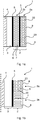
- Figures 1a and 1b illustrate two different example embodiments of a dry hybrid transformer 1.
- the dashed vertical line illustrates a fictive longitudinal central line of the transformer, such that half the transformer is schematically shown in longitudinal section, with turns of the windings of the conductor 7 of the cast HV winding 2b and the cable 20 of the cable HV winding 2a are running in a direction perpendicular to the plane of the section.
- a transformer core 4 and a LV winding 3 are schematically shown. These may be of any conventional, or other, design.
- An electrically insulating barrier(s) 5 separates the LV winding 3 from the HV winding 2.
- the conventional cast HV winding part 2b is schematically shown as turns of a conducting strip or discs 7 in a matrix of solid phase electrically insulating material 6, e.g. a cured epoxy or solidified thermoplastic polymer material such as polypropylene (epoxy is preferred since it is more heat and fire resistant), which has been moulded around the HV winding 2b.
- the cable winding part 2a of the HV winding 2 is schematically shown as turns of a cable 20 in a matrix of solid phase electrically insulating material 6, e.g. a cured epoxy or solidified thermoplastic polymer material such as polypropylene (epoxy is preferred since it is more heat and fire resistant), which has been moulded around the cable of the HV winding 2a.
- the insulating material 6 of the cable winding 2a is the same as insulating material in the cast winding 2b, preferably epoxy, but in other embodiments it is a different insulating material 6 than in the cast winding.
- the moulded insulating material 6, imparts improved heat and fire resistance to the cable winding 2a.
- the thickness of the insulating material 6 is preferably substantially lower in the cable winding 2a, in which there is electrical insulation also in the cable itself which also impairs the heat transfer, than in the cast winding 2b.
- the minimal thickness of the insulating material 6, as measured from the outer surface of the cable 20 anywhere in the cable winding 2a is preferably not more than a few millimetres, e.g. less than 10 mm or less than 5 mm.
- the insulating material 6 of the cable winding 2a (and/or of the cast winding 2b) may, in some embodiments, comprise a filler material for improved heat/fire resistance and/or mechanical properties.
- Such a filler material may be any electrically insulating filler material which improves the heat conduction of the insulating material 6, e.g. any of diamond powder, aluminium nitride (AlN), zinc oxide (ZnO), and boron nitride (BN), e.g. two-dimensional such as hexagonal, or three-dimensional, or other.
- AlN aluminium nitride
- ZnO zinc oxide
- BN boron nitride
- the two embodiments of figures 1a and 1b differ in that the transformer 1 of figure 1a exhibits a HV winding 2 in which the cable winding 2a is an outer winding concentrically outside of the cast winding 2b, while the transformer 1 of figure 1b exhibits a HV winding 2 in which the cable winding 2a is an upper winding positioned above and concentrically aligned with the cast winding 2b.
- Any other configuration of the HV winding 2 is also contemplated, e.g. with the cable winding 2a below the cast winding (e.g. inverse of the embodiment of figure 1b ) or with the cable winding concentrically inside of the cast winding (e.g. inverse of the embodiment of figure 1a ).
- the cable winding is illustrated as having turns in two concentric layers, while in the example of figure 1b , the cable winding 2a is illustrated as having turns in three concentric layers.
- any suitable number of turns in any suitable number of concentric layers in the radial direction or in the vertical direction may be used depending on the requirements for the transformer 1.
- An electrically insulating barrier layer 5 may separate the cable winding 2a from the cast winding 2b.
- FIG. 2 illustrates an embodiment of a HV cable 20 which may be used in embodiments of the cable winding 2a of the present invention.
- a conductor 21 e.g. a thread or wire of twisted threads, of a conducting material, typically a metallic material such as copper or aluminium.
- the wires are typically coated (natural oxidation or manually) with very thin electrically insulating layer.
- the conductor may e.g. have a substantially circular cross section of a diameter for instance within the range of from 10 mm to 30 mm, e.g. 20-30 mm.
- the conductor 21 is surrounded by an insulating concentric layer/sheath 22 of an electrically insulating material, e.g.
- the insulating material is heat and fire resistant, but typically not to the same high degree as the moulded insulating material 6, which is a reason why such an insulating material 6 may preferably be used as well outside of the cable 20.
- an additive or filler material with good electrically insulating and thermal properties e.g. any of silica and/or aluminium tri-hydrate (ATH), may be included in the insulating layer 22.
- Such an additive or filler may be relatively expensive, why it may in some embodiments only be mixed into the insulating layer 22 in particularly sensitive parts of the cable 20, e.g. at the beginning and/or the end of the cable winding 2a.
- the cable 20 also comprises a grounded layer/sheath 23, concentrically outside of the insulating layer 22.
- the grounded layer is at least partly electrically conducting to handle dielectric stress of the cable.
- the grounded layer may be metallic, but it may be preferred to use a semiconducting polymeric material, e.g. as in the DryformerTM transformer type cable winding.
- the grounded layer 23 may be called an insulation shield since it is positioned outside of the insulating layer 22 and protects the same.
- a similar or same semiconducting polymeric material may be used for a conductor shield 25 positioned concentrically between the conductor 21 and the insulating layer 22.
- the grounded layer 23 improves the handling of transient voltages, e.g. in case of a lightning strike, in the transformer 1.
- the cable may comprise a metal layer 24, concentrically positioned outside of the grounded layer 23, which metal layer 24 may be an outer layer of the cable 20, forming an outer surface of said cable, and which metal layer 24 may be in contact with the grounded layer 23 such that both the grounded layer 23 and the metal layer 24 are electrically grounded.
- the metal layer 24 may be called a metal shield or sheath and may be of any suitable electrically conductive metal, e.g. aluminium or copper, preferably copper.
- the metal shield is preferably thin enough to be flexible, to allow the cable 20 to be easily wound in the cable winding 2a.
- the metal layer 24 may thus have a thickness of less than 1 mm, e.g. less than 0.5 mm, 0.1 mm or 0.01 mm.
- a metal layer 8 which may have the same properties as the metal layer 24 (discussed above, if applicable) may be provided outside of (e.g. in contact with) the insulating material 6 of the cable winding 2a, e.g. forming an outer surface of the cable winding, or inside of (e.g. in contact with) the insulating material 6 of the cable winding 2a i.e. between the wound cable 20 and the insulating material 6 but not part of the cable.
- the metal layer 8 when outside of the insulating material 6 may e.g. be positioned between the insulating material 6 of the cable winding 6 and the LV winding 3 or the cast HV winding 2b or an outside of the transformer 1.
- Such an outer metal layer 8 may further improve the heat/fire resistance of the transformer 1.
- the cable 20, including the conductor 21 and its surrounding layers 22-25, may have a substantially circular cross section and/or may have a diameter within the range of 35-50 mm.
- the HV winding 2 further comprises a cast winding part 2b which, in contrast to the cable winding part 2a does not comprise a winding of the cable 20.
- a dry type transformer comprising a low voltage (LV) winding and a high voltage (HV) winding.
- the HV winding comprises a cast winding part and a cable winding part, wherein the cable winding part, in contrast to the cast winding part, comprises a winding of a cable.
- the cable comprises an electrical conductor forming a central part of the cable, an electrically insulating layer concentrically positioned outside of the conductor, and a grounded layer of an at least partly conducting material concentrically positioned outside of the insulating layer.
- the cable winding part comprises an electrically insulating material in solid state moulded around the cable.
Landscapes
- Engineering & Computer Science (AREA)
- Power Engineering (AREA)
- Insulating Of Coils (AREA)
Priority Applications (1)
| Application Number | Priority Date | Filing Date | Title |
|---|---|---|---|
| EP17157192.0A EP3364432A1 (de) | 2017-02-21 | 2017-02-21 | Brandschutz für eine trockenleistungswandlerwicklung |
Applications Claiming Priority (1)
| Application Number | Priority Date | Filing Date | Title |
|---|---|---|---|
| EP17157192.0A EP3364432A1 (de) | 2017-02-21 | 2017-02-21 | Brandschutz für eine trockenleistungswandlerwicklung |
Publications (1)
| Publication Number | Publication Date |
|---|---|
| EP3364432A1 true EP3364432A1 (de) | 2018-08-22 |
Family
ID=58314069
Family Applications (1)
| Application Number | Title | Priority Date | Filing Date |
|---|---|---|---|
| EP17157192.0A Withdrawn EP3364432A1 (de) | 2017-02-21 | 2017-02-21 | Brandschutz für eine trockenleistungswandlerwicklung |
Country Status (1)
| Country | Link |
|---|---|
| EP (1) | EP3364432A1 (de) |
Citations (7)
| Publication number | Priority date | Publication date | Assignee | Title |
|---|---|---|---|---|
| EP0901705A1 (de) * | 1996-05-29 | 1999-03-17 | Asea Brown Boveri Ab | Isolierter leiter für eine hochspannungswicklung |
| WO1999028926A2 (en) * | 1997-11-27 | 1999-06-10 | Abb Ab | A transformer/reactor and a method for manufacture of a transformer/reactor |
| WO2001075908A1 (en) * | 2000-04-03 | 2001-10-11 | Abb Power T & D Company Inc. | Dry type semi-conductor cable distribution transformer |
| WO2007010988A1 (ja) * | 2005-07-21 | 2007-01-25 | The Kansai Electric Power Co., Inc. | 高耐熱導線及び高耐熱電磁機器 |
| CN201570303U (zh) * | 2009-08-24 | 2010-09-01 | 上海索谷电缆集团有限公司 | 环保安全型耐火船用电力电缆 |
| US20110184092A1 (en) * | 2008-09-19 | 2011-07-28 | Abb Research Ltd | Epoxy resin composition |
| US20150109081A1 (en) * | 2013-10-21 | 2015-04-23 | Hammond Power Solutions, Inc. | Cast coil assembly with fins for an electrical transformer |
-
2017
- 2017-02-21 EP EP17157192.0A patent/EP3364432A1/de not_active Withdrawn
Patent Citations (7)
| Publication number | Priority date | Publication date | Assignee | Title |
|---|---|---|---|---|
| EP0901705A1 (de) * | 1996-05-29 | 1999-03-17 | Asea Brown Boveri Ab | Isolierter leiter für eine hochspannungswicklung |
| WO1999028926A2 (en) * | 1997-11-27 | 1999-06-10 | Abb Ab | A transformer/reactor and a method for manufacture of a transformer/reactor |
| WO2001075908A1 (en) * | 2000-04-03 | 2001-10-11 | Abb Power T & D Company Inc. | Dry type semi-conductor cable distribution transformer |
| WO2007010988A1 (ja) * | 2005-07-21 | 2007-01-25 | The Kansai Electric Power Co., Inc. | 高耐熱導線及び高耐熱電磁機器 |
| US20110184092A1 (en) * | 2008-09-19 | 2011-07-28 | Abb Research Ltd | Epoxy resin composition |
| CN201570303U (zh) * | 2009-08-24 | 2010-09-01 | 上海索谷电缆集团有限公司 | 环保安全型耐火船用电力电缆 |
| US20150109081A1 (en) * | 2013-10-21 | 2015-04-23 | Hammond Power Solutions, Inc. | Cast coil assembly with fins for an electrical transformer |
Similar Documents
| Publication | Publication Date | Title |
|---|---|---|
| JP3721359B2 (ja) | 発電電動機械のための段状の電界の絶縁システム | |
| JP4372845B2 (ja) | 電力変圧器/誘導器 | |
| JPH03236106A (ja) | 電気絶縁体 | |
| CN101836269A (zh) | 高电压室外套管 | |
| KR20130021420A (ko) | 와인딩들 내의 실딩 링들을 가진 트랜스포머 | |
| CA2612802A1 (en) | Non-linear dielectrics used as electrical insulation | |
| US20150031798A1 (en) | Composite materials for use in high voltage devices | |
| CN103493157B (zh) | 线缆及包括其的电磁设备 | |
| US2817066A (en) | Electric transformer | |
| SE510946C2 (sv) | Transformator/reaktor samt förfarande vid tillverkning av en sådan samt förtillverkad lindningsmodul | |
| US5250755A (en) | X-ray conduits | |
| SE510858C2 (sv) | Krafttransformator/reaktor | |
| US11605994B2 (en) | Winding insulation system | |
| US11145455B2 (en) | Transformer and an associated method thereof | |
| JP2018046264A (ja) | モールドコイル、変圧器及びリアクタンス | |
| CN108369855B (zh) | 带有柔性连接端子的干式铸造变压器 | |
| US20200194164A1 (en) | High Voltage Cable For A Winding And Electromagnetic Induction Device Comprising The Same | |
| EP2999092A1 (de) | Isolierung eines gewickelten Leiters und Verfahren zum Isolieren eines derartigen Leiters | |
| JP2010246247A (ja) | 絶縁コイル、及び回転電機機器 | |
| JP2015088513A (ja) | インダクタ | |
| KR102584633B1 (ko) | 복합쉬스층을 포함하는 전력케이블 | |
| JPS58157350A (ja) | 回転電機の絶縁コイル | |
| CN100533613C (zh) | 一种用特殊电缆绕组制成的分裂变压器 | |
| CN207663830U (zh) | 一种机车用控制电缆 | |
| CN106716788A (zh) | 电机的电晕屏蔽系统 |
Legal Events
| Date | Code | Title | Description |
|---|---|---|---|
| PUAI | Public reference made under article 153(3) epc to a published international application that has entered the european phase |
Free format text: ORIGINAL CODE: 0009012 |
|
| AK | Designated contracting states |
Kind code of ref document: A1 Designated state(s): AL AT BE BG CH CY CZ DE DK EE ES FI FR GB GR HR HU IE IS IT LI LT LU LV MC MK MT NL NO PL PT RO RS SE SI SK SM TR |
|
| AX | Request for extension of the european patent |
Extension state: BA ME |
|
| STAA | Information on the status of an ep patent application or granted ep patent |
Free format text: STATUS: THE APPLICATION IS DEEMED TO BE WITHDRAWN |
|
| 18D | Application deemed to be withdrawn |
Effective date: 20190223 |