EP3364825B1 - Vorrichtung für die zubereitung eines getränks mittels zentrifugation mit einem ventil in der getränkeabflussvorrichtung - Google Patents
Vorrichtung für die zubereitung eines getränks mittels zentrifugation mit einem ventil in der getränkeabflussvorrichtung Download PDFInfo
- Publication number
- EP3364825B1 EP3364825B1 EP16784905.8A EP16784905A EP3364825B1 EP 3364825 B1 EP3364825 B1 EP 3364825B1 EP 16784905 A EP16784905 A EP 16784905A EP 3364825 B1 EP3364825 B1 EP 3364825B1
- Authority
- EP
- European Patent Office
- Prior art keywords
- valve
- beverage
- state
- capsule
- rotational speed
- Prior art date
- Legal status (The legal status is an assumption and is not a legal conclusion. Google has not performed a legal analysis and makes no representation as to the accuracy of the status listed.)
- Active
Links
Images





Classifications
-
- A—HUMAN NECESSITIES
- A47—FURNITURE; DOMESTIC ARTICLES OR APPLIANCES; COFFEE MILLS; SPICE MILLS; SUCTION CLEANERS IN GENERAL
- A47J—KITCHEN EQUIPMENT; COFFEE MILLS; SPICE MILLS; APPARATUS FOR MAKING BEVERAGES
- A47J31/00—Apparatus for making beverages
- A47J31/22—Centrifuges for producing filtered coffee
-
- A—HUMAN NECESSITIES
- A47—FURNITURE; DOMESTIC ARTICLES OR APPLIANCES; COFFEE MILLS; SPICE MILLS; SUCTION CLEANERS IN GENERAL
- A47J—KITCHEN EQUIPMENT; COFFEE MILLS; SPICE MILLS; APPARATUS FOR MAKING BEVERAGES
- A47J31/00—Apparatus for making beverages
- A47J31/40—Beverage-making apparatus with dispensing means for adding a measured quantity of ingredients, e.g. coffee, water, sugar, cocoa, milk, tea
- A47J31/407—Beverage-making apparatus with dispensing means for adding a measured quantity of ingredients, e.g. coffee, water, sugar, cocoa, milk, tea with ingredient-containing cartridges; Cartridge-perforating means
Definitions
- the present invention relates to the field of the preparation of a beverage by centrifugation.
- it relates to a device for preparing a beverage such as coffee by using centrifugation to brew and extract the beverage from a receptacle.
- the preparation of a beverage by using centrifugation is known.
- the principle mainly consists in providing a beverage ingredient in a receptacle, feeding liquid in the receptacle and rotating the receptacle at elevated speed to ensure interaction of the liquid with the ingredient while creating a gradient of pressure of liquid in the receptacle; such pressure increasing gradually from the centre towards the periphery of the receptacle.
- WO 2008/148601 describes a possible example of a device using such principle wherein the receptacle is a capsule containing beverage ingredients. Hot water is fed in the centre of the capsule via a water interfacing part comprising a water injector aligned in the rotation axis. The receptacle is held in a capsule holder which is rotated by means of a rotary motor. Both the liquid interfacing part and the capsule holding part are mounted along ball bearings. The beverage is extracted from the capsule by a plurality of peripheral needles that creates openings through a lid of the receptacle.
- the capsule As the capsule is centrifuged about its rotation axis, hot water passes through the beverage ingredient, interacts with it to produce a liquid extract and the resulting liquid extract traverses, under the effect of the centrifugal forces, the peripheral openings and is projected against an impact wall of the collector.
- the liquid extract thus constituting the beverage, is then drained through a beverage duct of the device and collected into a recipient such as a cup.
- WO 2008/148646 and WO 2008/148650 further describe a beverage preparation device wherein a flow restriction is created downstream of the receptacle, in particular a capsule, for example, by a valve system which opens or enlarges under the pressure created by the centrifuged liquid leaving the receptacle.
- the valve system can be formed by a mobile restriction part of the device which is elastically urged against a rim portion of the capsule.
- the present invention aims at providing such centrifugal beverage production device with means modifying the characteristics of a beverage produced.
- the produced coffee beverage when being dispensed in a beverage receptacle, presents a so-called "crema" on its surface.
- the coffee beverage is also produced with less or little 'crema' or even with substantially no 'crema' at all. Therefore, the flexibility to adjust the beverage characteristics, more particularly, the amount of 'crema' in the coffee beverage is desired.
- a device for preparing a beverage from a substance contained in a capsule comprises:
- the beverage draining means comprise at least one valve. Furthermore, at least one external valve operating means is arranged for controlling the state of the valve in order to modify the flow resistance of the beverage draining means. "External” is to be understood such that such valve operating means apply a force from outside the beverage draining means. This is in contrast to forces which the flowing beverage inside may produce against the inner wall or other elements inside the beverage draining means.
- the external valve operating means may be arranged to control the state of the valve such that the higher the rotational speed, the higher the closing force of the valve.
- the closing force will typically act against the forces generated by the centrifuged beverage against the valve member, such that the valve state will finally be in an equilibrium state.
- the flow rate of the beverage is a function of the rotational speed.
- a flow rate control may be implemented which controls the rotational speed such that a desired flow rate is achieved.
- the flow rate control may comprise a flow rate sensor feeding back the actual flow rate.
- the flow resistance of the beverage draining means is a function of the rotational speed, thus also the flow resistance of the beverage draining means is a function of the flow rate control. The higher the flow rate, the higher the rotational speed and thus the higher the flow resistance of the beverage draining means.
- the external valve operating means control the closing force, but not the absolute state of the valve (which is the result of an equilibrium of forces as discussed above).
- the external valve operating means may control the absolute state of the valve ("position control”, e.g. by increasing the closure force until the absolute state is reached).
- the valve may be controlled such that the flow resistance is higher at a first rotational speed than at a second rotational speed, wherein the second rotational drive speed is lower than the first rotational speed.
- the first and second rotational speeds are not related to a particular sequence of rotational speeds and may be applied selectively for preparing a beverage depending on the characteristics of extraction desired.
- the valve operating means may control the state of the valve such that the flow resistance of the beverage draining means increases in at least one subrange or the total of the range of the adjustable rotational speed.
- the valve operating means may control the state of the valve such that
- the valve operating means may control the state of the valve such that the valve
- the beverage draining means may comprise a section which is arranged to be rotatable together with the capsule holder, and wherein the at least one valve is arranged in the rotatable section of the beverage draining means.
- the rotatable section may be a liquid interfacing part of the device arranged for supporting the valve.
- the external valve operating means may comprise a valve member, e.g., a valve compressing member, which is arranged to be displaced in a flow resistance increasing direction by centrifugal forces when the rotatable section of the beverage draining means and thus the mass of the valve member (or another mass connected to the valve member) is rotated.
- a valve member e.g., a valve compressing member
- valve member e.g., valve compressing member
- the valve member may be arranged to be displaceable in rotation and/or translation.
- the displacement of the valve member is effective between a state of low (or substantially no) flow resistance to a state of higher flow resistance of the valve.
- the valve may comprise restoring force means biasing the valve towards the state of lower flow resistance.
- the restoring force means is arranged to act against the valve member.
- the restoring force means may be for example a spring element arranged to bias the valve towards the state of lower flow resistance.
- the spring element can be external to the walls of the beverage draining means.
- the restoring force means may be an integral resilient wall part of the beverage draining means arranged to engage the valve towards the state of lower flow resistance.
- the restoring force means e.g. spring element
- the restoring force means forces the valve to return to a state of lower flow resistance when the rotational speed is lower or equal than a threshold rotational speed.
- the restoring force means does not provide a sufficient effort on the valve to return it to the state of lower flow resistance.
- the restoring force means e.g. spring element
- the restoring force means is arranged to oppose the displacement of the valve member toward the state of higher flow resistance. Therefore, in absence of rotation or at a lower rotational speed, the restoring force means maintains the valve member in a position in which the valve is maintained open.
- the valve may comprise a flexible membrane arranged to vary the free cross-section of the beverage draining means when displaced. This action of the flexible membrane thereby determines the flow resistance of the beverage draining means.
- the device may comprise capsule identification means and/or user interface means.
- the means for operating the state of the valve may be designed to control the state of the valve based on information provided by the capsule identification means and/or user interface means.
- a further aspect of the invention relates to a method for preparing a beverage from a substance contained in a capsule, the capsule being placed in a beverage production device,
- the invention also provides a beverage device for preparing a beverage by centrifugation, from a capsule rotated in the device, comprising:
- the external valve operating means are arranged or controllable according to these two different states of the valve in a manner that in the second state of the valve, the rotational speed/speeds is/are set at higher value/values than in the first state of the valve.
- the valve comprises at least one valve member, e.g., a valve compressing or closing member, arranged to be movable from the first state towards the second state of the valve by the action of the centrifugal force which exerts on the valve member.
- the valve member can be a pivot member, pivotable by the action of the centrifugal forces for pressing on at least one soft, elastic membrane which is arranged for restricting the flow opening cross-section of the valve when such pressing action is engaged.
- the pivot member preferably comprises at least one mass of inertia, e.g., a metal piece having a density higher than 7, preferably higher than 8.
- the invention relates to a beverage device for preparing a beverage by centrifugation, from a capsule rotated in rotating parts of the device and containing ingredients comprising:
- valve actuation member can be arranged on one of the rotating part, preferably on the liquid interfacing part, so as to pivot or translate as a result of or under the action the centrifugal forces applied thereon.
- the device can comprise a biasing means, such as a spring element, arranged with the valve actuation member to apply a biasing force on the valve actuation member which is opposed to the direction corresponding to a reduction of the beverage flow cross-section of the valve.
- a biasing means such as a spring element
- the biasing means is configured such that when the rotational speed of the rotating parts is below or at a threshold value, the valve actuation member takes a first state in which the beverage flow cross-section of the valve is enlarged or open and, when the rotational speed of the rotating parts is above the threshold value, the valve actuation member takes a second state forcing a reduction of the beverage flow cross-section of the valve compared to the enlarged or open position.
- the valve may take different relative positions as to the reduction of the flow cross section that essentially depends on the rotational speed and the pressure of beverage acting on the valve.
- the moving or deforming part of the valve can be an elastic membrane.
- the elastic membrane can be moved and/or deformed as a response to the movement of the valve actuation member combined to the pressure of the beverage flow through the valve and contacting the membrane.
- the moving or deforming part of the valve can be a portion of elastically deformable conduit guiding the flow of beverage.
- the elastically deformable conduit can be deformed, in particular by its cross section narrowing, as a response to the movement of the valve actuation member combined to the pressure of the beverage flow through the conduit.
- the invention also relates to a system comprising a beverage preparation device as aforementioned and a capsule containing beverage ingredients.
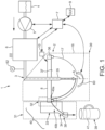
- the device 1 of the invention generally comprises as known ⁇ per se' a centrifugal brewing unit 2 for receiving and centrifuging a receptacle such as a removable capsule 17.
- the centrifugal brewing unit 2 is designed for preparing a beverage such as coffee, from both a beverage ingredient contained in the capsule 17 and water injected in the capsule 17.
- the injected water interacts (such as by brewing or mixing) with the beverage ingredient and, by virtue of the centrifugal forces, a beverage extract is obtained which is forced to leave the capsule 17 at its periphery.
- the unit 2 is placed in liquid communication with a liquid supply line 3 intended for supplying a heated liquid, preferably water, from a reservoir 4 to the unit 2.
- the liquid is circulated through the line 3 by a pump 5.
- the pump 5 can be of any suitable type such as a piston pump, a diaphragm pump, a gear pump or a peristaltic pump, for example.
- a heater 6 is provided along the liquid supply line to heat the liquid at a temperature above ambient temperature. The temperature may vary depending on the beverage to be extracted. For instance, for coffee, water can be heated between about 70 and 100 degrees Celsius.
- the brewing unit 2 comprises two rotating parts 30 connected together, in particular, a liquid interfacing part 8 and a holding part or capsule holder 16.
- the two parts 8, 16 are designed for holding the capsule 17 containing a beverage ingredient.
- the device 1 further comprises a rotational driving means 60 such as a rotary electric motor which is coupled to one of the rotating parts of the brewing module such as the holding part 16 via a coupling means.
- the rotating parts are arranged in closure, i.e. are connected together by connections at least during rotation in such a manner that these parts 8, 16 rotate together about an axis A with the capsule 17 during centrifugation.
- the capsule holder 16 may take various configurations and may not necessary be completely separable from the first rotating part.
- a control unit 7 is also provided to control the brewing operation, in particular, the rotational speed of the rotating parts 30 via the motor, the temperature of the liquid provided by the heater 6 and other operations such as the flow rate and amount of liquid supplied by the pump 5.
- a flow meter 62 can be positioned in the flow liquid supply line to measure the liquid flow and provide input to the control unit 7.
- the control unit 7 may also receive information from a user interface 9 and/or a capsule identification system 10.
- An example for such capsule identification system is a bar code reader 10 underneath the rim of the capsule 17.
- the liquid interfacing part 8 can comprise an injector 35 designed for supplying (e.g. injecting) a liquid like water in the (e.g. along the rotational center axis of the) capsule 17.
- the injector 35 On its upper end, the injector 35 is in liquid communication with the liquid supply line 3. Additional liquid control means such as a check valve may be provided upstream the injector 35.
- a series of beverage extracting means 36 At the periphery of the lower surface of the liquid interfacing part 8 is located a series of beverage extracting means 36 designed to perforate the inlet wall 37 of the capsule 17 in multiple zones to provide multiple beverage outlets for finally extracting the beverage from the capsule 17. The peripheral outlets are thus created in the inlet wall 37 close to the rim of the capsule 17 where the centrifugal forces are the highest.
- the beverage outlets could also be pre-made in the capsule 17 before insertion of the capsule 17 in the device 1. It could also be that the rim of the capsule is formed as a plurality of outlets for the centrifuged liquid.
- the means 40 for draining the beverage from the capsule comprise a first section 40a (when seen in the flow direction of the produced beverage) which is part of the rotating parts 30 of the beverage production device 1.
- An interface 32 is provided at which the beverage is guided ("handed over") from the first rotating section 40a to a second section 40b of the beverage draining means 40, which second section 40b is part of the static parts 31 of the beverage production device.
- the second (static) section 40b comprises a collector 33, a collector exit 34 leading to a beverage production device outlet 38 arranged to guide the beverage into a beverage receptacle 39.
- a rotational seal is provided between the rotating parts 30 and the static (stationary) parts 31 of the beverage production device.
- means are provided for altering beverage characteristics by controlling the flow characteristics, such as the flow resistance of the beverage draining means 40.
- Such means for changing the flow characteristics can be provided in the first (rotatable) part 40a and/or the second (static) part 40b of the beverage draining means.
- these means for modifying the flow characteristics of the beverage draining means comprise a valve 50 in the particular mode of figures 2a , 2b .
- the inventors have found out that modifying the flow characteristics, especially the flow resistance of the beverage draining means 40 has an impact on the characteristics of the produced beverage.
- increasing the flow resistance of the beverage draining means 40 causes a pressure drop which in turn promotes the production of the so-called "crema”.
- the "crema” 41 will actually occur when the beverage is dispensed in the beverage receptacle 39 ("in-cup crema").
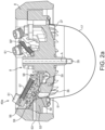
- FIGS 2a , 2b show an embodiment in which such flow characteristic modifying means comprise a valve 50 arranged in the rotatable first section 40a of the beverage draining means 40.
- a valve 50 arranged in the rotatable first section 40a of the beverage draining means 40.
- the valve 50 are arranged within the liquid interfacing part 8 in which also the injector 35 is arranged.
- the centrifuged beverage drained from the rotating capsule 17 is guided upwards (i.e. in a direction substantially perpendicular or inclined radially outwards when seen in the beverage flow direction) to the inlet wall of the capsule 17 through a first (e.g. essential axial or vertical) channel 51 of rotatable first section leading to the valve 50.
- the axial or vertical channel 51 leads to a bend section 52 of the beverage draining means 40.
- this bend section 52 forms an angle in the order of 60 degrees to 120 degrees and preferably 80 degrees to 100 degrees in the shown example.
- the valve 50 according to this example is arranged in the bend section 52 of the first (rotatable) section 40a of the beverage draining means 40. Downstream of the valve 50 (when seen in the beverage flow direction) a (e.g. essentially radial or horizontal) draining channel 53 is provided, which leads for example to the interface 32 shown in figure 1 and, thus, towards the second (static) section 40b of the beverage draining means 40.
- the second static section 40b collects the beverage from the rotating parts and guide it to the receptacle 39.
- valve 50 comprises a membrane 54 which is mounted in a rotatable manner around a rotation axis 55. It is to be understood that other valve designs are possible in which such membrane 54 or other valve element are arranged in a manner such that they are movable in translation (i.e. essentially linearly) and/or in combined rotation and translation.
- the membrane may be made from silicone or any other food grade elastic material.
- the membrane 54 is mounted on a pivot means 56, which pivot means 56 is mounted in a rotatable manner in the rotating part or liquid interfacing part 8 of the beverage production device 1 by means of the rotation axis 55.
- the pivot means 56 is one example for external valve state operating means. When rotated, the mass of the pivot means 56 (and any mass fixedly connected thereto) generates a centrifugal force, which one example of a force generated "externally", i.e. not internally (inside the beverage draining means) by flowing beverage. This external force is then used to control the change of the state of the valve 50.
- a least one additional mass 61 is shown which is attached (e.g., screwed) to the pivot means 56 to adjust and increase the centrifugal forces upon rotation.
- the forces for closing the valve 50 (or reducing its flow cross-section) in the shown example are generated by centrifugal forces caused by the rotation of a mass of inertia including the pivot means 56.
- the centrifugal forces will cause a rotation or pivoting of the membrane 54 (against the clock in the shown example) around the axis 55 (which is an axis perpendicular to the rotation axis of the capsule and preferably perpendicular to a radial direction of the capsule in the transversal section of Fig. 2a ), which rotation will cause an increase of the flow resistance of the beverage draining means.
- the rotation of the membrane is just an example for a control of the valve state towards a state in which the valve increases the flow resistance of the beverage draining means 40.
- biasing means or restoring force means such as a helicoidal spring 57 are provided which bias the valve 50 towards the open state.
- the radially inner end 58 of the helicoidal 57 spring is mounted offset to the rotation axis 55 by a distance d, such that the helicoidal spring 57 produces a torque in the clockwise direction in example of figure 2a , 2b .
- the helicoidal spring 57 or other biasing means are pre-stressed, such that in a first rotational speed range no state change of the valve 50 occurs until the centrifugal forces overcome the pre-stressing force of the helicoidal spring 57. This will be further explained with reference to figure 3 .
- valves 50, 50' with associated channels 51, 53 of the beverage draining means may be arranged in the rotational part 30 of the beverage production device 1.
- three valves 50, 50' are arranged regularly spaced at an angular distance of 120°.
- the number of valves is not limited to three and can be 4, 5 or 6.
- figure 2b shows the state in which the valve 50 is in a state in which the flow resistance of the beverage draining means 40 is lower (“open state")
- figure 2a shows the state in which the valve 50 is in the "closed” state. It is to be understood that “closed” does simply mean a state in which the valve 50 is in a state such that the flow resistance of the beverage draining means 40 is higher compared to the open state of figure 2b . However, even in the closed state the valve 50 is not completely shutting off the beverage draining means 40 or channel 51.
- valve will be in a state with higher flow resistance in which there is an equilibrium between the valve closing force (essentially the difference between the centrifugal force and the biasing force of the helicoidal spring 57) and the force produced by the beverage coming from the channel 51 and acting on the valve.
- beverage In such closed state there will be a restricted cross section of the beverage flow in the area of the valve 40.
- This beverage is typically pressurized also by means of the centrifugal forces.
- beverage may also flow in the closed state of the valve 50.
- the pressure drop and the pressure upstream of the valve 50 are increased in the closed state of the valve 50 when compared to the open state of the valve 50. It is thought that this increased pressure drop promotes the production of the crema in the finished beverage product.
- the rim 59 of the membrane 54 is sealed to the parts, e.g. the bend section 52 and pivot means 56, in which the channels 51 and 53 are formed.
- the parts e.g. the bend section 52 and pivot means 56, in which the channels 51 and 53 are formed.
- beverage coming from the channel 51 cannot leak in the area of the valve 50, but rather will still have to exit through the radial or horizontal channel 53 (the path of liquid is illustrated by arrows "L"). Due to this sealing of the rim 59 of the membrane 54, the inner part of the membrane will be pushed by the pivot means 56 towards a closed state of the valve at high rotational speeds.
- the membrane is moved by the hinged pivot means 56.
- the hinged pivot means 56 is an example of external valve controlling means. "External” is to be understood such that such valve operating means apply a force from outside (relative to the beverage draining means). This is in contrast to internal forces acting on the beverage draining means and generated e.g. by the centrifuged beverage when acting against the inner walls or other elements inside the beverage draining means.
- the valve state according to the invention thus is a function of such control forces produced by the external valve control means.
- the membrane is an example of a valve member which is part of the wall of the beverage draining means.
- the valve member can additionally or alternatively also be located within the beverage draining means.
- the membrane is an example of a flexible wall of the beverage draining means being part of the valve.
- the beverage draining means may present rigid walls, not deformed when changing the state of the valve.
- a movable valve member is provided within the walls of the beverage draining means.
- the membrane is a movable part of the beverage draining means, acting against static parts of the beverage draining means.
- the valve may comprise more than one movable part.
- the state of the valve is modified by changing the rotational speed of the capsule and the rotating parts of the beverage production device.
- the production of "crema" on top of a coffee beverage can be controlled by adapting the rotational speed during the beverage production process.
- the valve state can also be changed within the beverage production process such that e.g. the valve is only closed during a time period smaller than the entire beverage production process.
- the crema production can be "promoted at the end of the beverage production process.
- the duty cycle during which the valve is closed is at least one parameter of the beverage production process determining the amount and/or the quality of the crema.
- valve state is not modified by the rotational speed but, for example, by enabling/blocking means, which may selectively block the change of the valve state such that the valve state will remain in its current state even when the rotational speed is changed.
- enabling/blocking means which may selectively block the change of the valve state such that the valve state will remain in its current state even when the rotational speed is changed.
- the production of crema can be disabled or blocked independently of the rotational speed.
- valve state control means are purely mechanical.
- the valve control means in this embodiment can be viewed as “passive” elements as the driving force for the valve state change, i.e. the centrifugal force, "passively" is generated by the rotation.
- the valve control means may comprise an active actuator driving the modification of the valve state independently of the rotation.
- valve state control means may be at least one electrically-driven actuator such electro-mechanical, electrical, electromagnetic or induction actuator, such as a solenoid, electromagnet(s), electrical motor(s), and the like.
- the valve state may be controlled completely independently from the rotational speed. Rather, the valve state may be controlled at any suitable rotational speed. The switching of the valve state thus may involve electric signals send to the one or more electrically driven actuators.
- the modification of the valve towards the flow resistance increasing state may be performed each time a beverage production process is run. Alternatively it may be performed selectively, i.e. dependent on a signal from a capsule identification device 10 of the beverage production device (involving the detection of an identification feature of the capsule) and/or a signal from a user interface 9 (touch screen, remote control, switches and the like) respectively communicating with the control unit 7.
- a signal from a capsule identification device 10 of the beverage production device involving the detection of an identification feature of the capsule
- a user interface 9 touch screen, remote control, switches and the like
- valve operating means do not involve a feedback mechanism in order to implement a feedback control.
- sensing means can be arranged on or within the beverage draining means sensing e.g. the pressure or the pressure drop of the beverage at the valve or alternatively the flow rate of the beverage.
- the pressure or flow rate sensing means may also be arranged in the inlet tube 3 for the liquid supplied to the capsule 17.
- the control unit 7 may communicate with the valve state control means and can implement a feedback control of the state of the valve such that the sensed parameter (pressure, speed, of the beverage, etc.) can be controlled to a given nominal value.
- the nominal value can be dependent on the rotational speed, by providing a nominal value/rotational speed table, curve or function.
- the nominal value may develop (vary) along with an ongoing beverage production process.
- Fig. 3 shows an example of a possible working curve of the pressure drop as a function of the rotation speed for a device of the invention. This is one example of a valve state control depending on or triggered (e.g. by centrifugal forces) on the rotational speed.
- a zero backpressure in Fig. 3 is achieved in the open state of the valve.
- valve is kept open, and the backpressure at the valve thus kept zero, between 0 rpm and a threshold rotational speed.
- threshold rotational speed the valve is switched in the closed state. It is to be understood that on the closed state the produced beverage may still pass the valve, although with increased flow resistance.
- the flow resistance and thus the backpressure increases e.g. with the square of the increasing rotational speed. It is also possible that above the threshold rotational speed the backpressure remains constant or increases according to a different, e.g. linear function by correspondingly controlling the valve (e.g. by using a feedback control using backpressure sensing means).
- valve is controlled such that the backpressure increases starting from a zero-value rotational speed.
- keeping the valve open until the threshold rotational speed is reached has the advantage that after a beverage has been produced, the liquid delivery to the capsule is stopped and the capsule can be completely emptied by rotating it with a rotational speed between a zero-value rotational speed and the threshold rotational speed.
- the capsule can be emptied while the valve in the beverage draining means is in the maximum opened state and the beverage draining means thus present the smallest flow resistance.
- a second embodiment of the beverage production device of the invention is illustrated in Figs. 4-9 .
- the main difference lies in the beverage draining means comprising a circumferential valve 50 at the periphery of the rotatable liquid interfacing part.
- the valve comprises a continuous annular membrane 54.
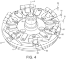
- the external valve operating means comprises a plurality of pivot means distributed along the circumference of the liquid interfacing part 8 ( Fig. 7 ).
- the pivot members are responsive to the centrifugal force when the part rotates and so arranged to control the state of the circumferential valve.
- the membrane can be made of soft and elastic material such as silicone rubber or thermoplastic elastomer.
- the membrane 54 is positioned above a pressure chamber 63 that is also annular and continuous at the periphery of the liquid interfacing part.
- a hard valve actuation ring 64 is further provided which is positioned adjacent the annular membrane 54 to act on the membrane for closing the chamber 63 upon a force is exerted thereon by the pivot means.
- the valve actuation ring 64 has a plurality of protrusions 65 evenly distributed on its upper surface; each protrusion being positioned in an aperture 66 of an upper disc-shaped support portion 67 of the liquid interfacing part.
- Each pivot means 56 is provided above the apertures 66 with a cam surface 68 that is arranged to engage the protrusion 65 of the actuation ring when rotated in a privileged direction (e.g. in clockwise direction).
- the pivot means 56 are mounted in a pivotable manner in the support portion 67.
- the axis of pivot 55 of each pivot means is preferably perpendicular to a radius of the liquid interfacing part. As a result, the pivot means are capable of rotating in radial directions by the effect of the centrifugal forces when the liquid interfacing means is rotated.
- the pivot means 56 comprises a mass of inertia 61 (e.g. copper piece) at its free end opposite the cam surface.
- the mass of inertia amplifies the lever force created by the cam surface on the actuation ring.
- the actuation ring is further linked to a plurality of spring elements 57.
- the spring element 57 is arranged, such as in a recess of the liquid interfacing part, to pull the actuation ring in a direction (A) away from the closing position of the membrane in the chamber ( Fig. 6 ).
- the spring element 57 acts in traction via a linkage formed by an intermediate arm 69 attached to a pin 70 of the actuation ring.
- the position of the spring elements can be angularly offset relative to the pivot means 56, for providing a sufficiently compact structure. However, many other arrangements are possible.
- the pressure chamber 63 is preferably annular and outwardly delimited by a annular restriction ridge 71 which is engaged by the soft elastic membrane when the pivot means are moved against it via the valve actuation ring. Therefore, the beverage flow can distribute in the pressure chamber 63 in the circumferential direction (B).
- the annular restriction ridge can be provided alternatively or additionally on the surface of the soft membrane.
- the valve In particular, at low rotational speeds (i.e., at or under a certain threshold) of the device, the valve remains open with the soft elastic membrane in disengaged position ( Fig. 6 ) and the spring element pulling the actuation ring in direction (A) away from the pressure chamber.
- the chamber is open and beverage can flow from the capsule and channel 51, to the interfacing part and the pressure chamber 63 and be centrifuged in outward direction (L).
- the backpressure exerted in the pressure chamber is low and depends on the restriction opening 72 between the restriction ridge 71 and the soft membrane 54. This restriction opening can be determined to provide more or less crema.
- the pivot means 56 When the rotational speed increases, the pivot means 56 are pivotally moved in the radial directions by the centrifugal forces.
- the pivot means act via their cam surfaces on the actuation ring and press the soft membrane towards the pressure chamber.
- the actuation force is directed towards the soft membrane (direction C in Fig. 5 ) and counters the traction force of the spring element (direction A in Fig. 6 ).
- the centrifugal force F L coming from the centrifuged liquid in the conduit 51 and pressure chamber also tends to maintain the soft membrane at least partially open and adds to the force of the spring F A .
- a dynamic pressure equilibrium is therefore obtained in which, at a sufficient rotational speed, or speed range, the valve exerts on the beverage a backpressure (higher than at low rotational speed) and the liquid can be expelled from the pressure chamber.
- the backpressure is such that crema is generated in the finished beverage product.
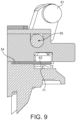
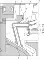
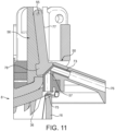
- the valve 50 comprises a compressible beverage conduit 73 which is arranged for being compressed by a compressing member 74.
- the compressing member is arranged to move by effect of the centrifugal forces (direction F c ) which exert when the capsule is rotationally driven by the liquid interfacing part 8 and a capsule holder 16.
- the compressing member is connected to a spring element 57 arranged for maintaining the compressing member in a non-compressing state of the conduit when sufficiently low centrifugal forces are present, i.e., at sufficiently low rotational speeds or within a low speed range.
- the spring element 57 can be fixedly connected to the rotatable part 8.
- the beverage conduit In the non-compressing state, the beverage conduit is maintained sufficiently open so that no or low hindrance of the beverage flow is provided. In this state, the backpressure created by the valve 50 is inexistent or low. As the centrifugal force increases, i.e., at higher rotational speeds or within a higher range of rotational speeds, the compressing member is forced in compression against the compressible conduit 73 (flow resistance increasing direction). In this second state, the conduits deforms and a restriction is created as the cross-section of the conduit diminishes thereby creating a backpressure on the beverage flow.
- the compressible conduit in the beverage draining means may form only a portion of the whole beverage conduit. It may be a soft tube such as silicone or nitrile-rubber tube. For instance, it may extend from a beverage inlet 75 at the inner surface of the liquid interfacing part to a beverage outlet 76 positioned in front of the beverage collector 33.
- the valve 50 comprises a compressible conduit 73 which embeds the biasing or force restoring means 57.
- the biasing means can be formed by at least one portion of wall of the conduit or by the conduit itself which deforms elastically under the pressure of a compressing member.
- the compressing member can form a pivot means 56 with a pivotable arm 77 hinged at a hinge or rotation axis 55 and a compressing portion 78 forming the free end of the compressing member.
- the compressing portion may be enlarged compared to the arm so as form a centrifugal mass of inertia that imparts a significant closure force on the compressible conduit 73 when being submitted to centrifugal forces.
- the conduit may be given a non-circular cross section at the surface where it is squeezed by the compressing member.
- the compressing member may translate rather than rotate.
- Fig. 12 provides a variant in which the valve is operated by external valve operating means which control the state of the valve independently from the centrifugal forces during rotation of the capsule and capsule holder.
- the valve 50 comprises a valve or drive actuator 79 which controls the states of the valve when receiving a dedicated input from the control unit.
- the valve actuator can be a solenoid which acts on a valve compressing member 74.
- the valve compressing member 74 engages a resilient compressible conduit 73, e.g. by pinching such conduit.
- a first state (dotted lines)
- the valve actuator is retracted in such a manner that the conduit is uncompressed and the backpressure created by the valve is relatively low. This state preferably corresponds to low rotational speeds of the liquid interfacing part.
- valve actuator 79 In a second state (full lines), the valve actuator 79 is extended to force the compressing member 74, in the flow resistance increasing direction, to pinch the conduit sufficiently to create a significant backpressure.
- the conduit is significantly deformed thereby hindering the flow of centrifuged beverage.
- This state preferably corresponds to higher rotational speeds.
- the transition from one state to the other can be triggered by the control unit in response to an input reflecting the rotational speed of the capsule in the device.
- the flow rate of liquid injected in the capsule is controlled by the pump which is controllable by the control unit at variable flow rates (pump 5 of Fig. 1 ).
- Such flow rate can be varied independently from the operation of the valve.
- the flow rate can be adjusted at a higher value when the valve is in fully open state and be decreased when the valve is in a restriction or high backpressure state.
Landscapes
- Engineering & Computer Science (AREA)
- Food Science & Technology (AREA)
- Apparatus For Making Beverages (AREA)
- Centrifugal Separators (AREA)
Claims (15)
- Vorrichtung (1) zum Zubereiten eines Getränks aus einer Substanz, die in einer Kapsel (17) enthalten ist,die Vorrichtung (1) umfassend:- einen Kapselhalter (16), der zum Halten einer solchen Kapsel angeordnet ist,- Mittel (7, 60) zum drehenden Antreiben der Kapsel mit einer einstellbaren Drehgeschwindigkeit,- eine Flüssigkeitszufuhreinheit (3, 35) zum Zuführen von Flüssigkeit in die Kapsel, und- Getränkeablassmittel (40) zum Ablassen eines Getränks, das in der Kapsel (17) produziert wird,die Getränkeablassmittel (40) umfassend mindestens ein Ventil (50), wobei mindestens ein externes Ventilbetätigungsmittel (56, 57, 58, 61, 74, 77, 78, 79) eine Kraft von außerhalb der Getränkeablassmittel (40) ausübt, die angeordnet sind, um den Zustand des Ventils (50) zu steuern, wobei die Kraft nicht durch Getränk produziert wird, das im Inneren und gegen eine Innenwand oder ein anderes Element der Getränkeablassmittel fließt,dadurch gekennzeichnet, dass die Kraft von außerhalb der Getränkeablassmittel (40) angeordnet ist, um den Zustand des Ventils (50) zu steuern, um den Flusswiderstand der Getränkeablassmittel (40) zu modifizieren.
- Vorrichtung nach Anspruch 1,
wobei die externen Ventilbetätigungsmittel (56, 57, 58, 61, 74, 77, 78, 79) angeordnet sind, um den Zustand des Ventils (50) derart zu steuern, dass je höher die Drehgeschwindigkeit ist, umso höher die Schließkraft des Ventils ist. - Verfahren nach Anspruch 1 oder 2,
wobei die Drehgeschwindigkeit durch Flussratensteuermittel (7, 62) eingestellt wird, die die Flussrate derart einstellen, dass eine gewünschte Flussrate des Getränks erreicht wird. - Vorrichtung nach einem der vorstehenden Ansprüche,
wobei die Ventilbetätigungsmittel (56, 57, 58, 61, 74, 77, 78, 79) den Zustand des Ventils derart steuern können, dass der Flusswiderstand der Getränkeablassmittel (40) in mindestens einem Teilbereich oder dem Gesamten des Bereichs der einstellbaren Drehgeschwindigkeit zunimmt - Vorrichtung nach einem der vorstehenden Ansprüche,wobei das Ventil (50) derart gesteuert wird, dass der Flusswiderstand der Getränkeablassmittel (40) bei einer ersten Drehgeschwindigkeit höher als bei einer zweiten Drehgeschwindigkeit ist,wobei die zweite Drehantriebsgeschwindigkeit niedriger als die erste Drehgeschwindigkeit ist.
- Vorrichtung nach einem der Ansprüche 1 bis 5,
wobei die Ventilbetätigungsmittel (56, 57, 58, 61, 74, 77, 78, 79) den Zustand des Ventils derart steuern, dass:- sich das Ventil in einem Zustand von niedrigerem Flusswiderstand befindet, wenn die Drehgeschwindigkeit zwischen 0 U/min und einer Schwellendrehgeschwindigkeit ist, und- sich das Ventil in einem Zustand von höherem Flusswiderstand befindet, wenn die Drehgeschwindigkeit höher als die Schwellendrehgeschwindigkeit ist. - Vorrichtung nach Anspruch 6,
wobei, wenn die Drehgeschwindigkeit höher als die Schwellendrehgeschwindigkeit ist, die Ventilbetätigungsmittel den Zustand des Ventils derart steuern, dass das Ventil- den Flusswiderstand mit zunehmender Drehgeschwindigkeit steigert, oder- den Flusswiderstand mit zunehmender Drehgeschwindigkeit konstant hält. - Vorrichtung nach einem der vorstehenden Ansprüche,wobei die Getränkeablassmittel (40) einen Abschnitt (40a) umfassen, der angeordnet ist, um zusammen mit dem Kapselhalter (16) drehbar zu sein, undwobei das mindestens eine Ventil (50) in dem drehbaren Abschnitt (40a) der Getränkeablassmittel angeordnet ist.
- Vorrichtung nach Anspruch 8,
wobei die externen Ventilbetätigungsmittel ein Ventilelement (56, 74), z. B. ein Ventilkompressionselement, umfassen, das angeordnet ist, um durch Zentrifugalkräfte in eine den Flusswiderstand erhöhende Richtung verlagert zu werden, wenn eine Masse des Ventilelements oder eine Masse (61, 74, 78), die damit verbunden ist, gedreht wird. - Vorrichtung nach Anspruch 9,
wobei das Ventilelement (56) angeordnet ist, um in Drehung und/oder in Translation verlagerbar zu sein. - Vorrichtung nach einem der vorstehenden Ansprüche,
umfassend Rückstellkraftmittel (57), die das Ventil in einen Zustand mit verringertem Flusswiderstand vorspannen. - Vorrichtung nach Anspruch 11,wobei das Rückstellkraftmittel ein Federelement (57) außerhalb der Wände der Getränkeablassmittel (40) ist, oderwobei das Rückstellkraftmittel ein integraler elastischer Wandteil der Getränkeablassmittel ist.
- Vorrichtung nach einem der vorstehenden Ansprüche,
wobei das Ventil eine flexible Membran (54) umfasst, die angeordnet ist, um bei Verlagerung den freien Querschnitt der Getränkeablassmittel (40) zu variieren. - Vorrichtung nach einem der vorstehenden Ansprüche,
umfassend Kapselidentifizierungsmittel (10) und/oder Benutzerschnittstellenmittel (9), wobei Ventilbetätigungsmittel, die den Zustand des Ventils steuern, ausgelegt sind, um den Zustand des Ventils basierend auf Informationen zu steuern, die durch die Kapselidentifizierungsmittel und/oder die Benutzerschnittstellenmittel bereitgestellt werden. - Verfahren zum Zubereiten eines Getränks aus einer Substanz, die in einer Kapsel (17) enthalten ist, wobei die Kapsel (17) in eine Getränkeproduktionsvorrichtung (1) platziert wird,wobei das Verfahren umfasst:- Drehantreiben der Kapsel (17) mit einer einstellbaren Drehgeschwindigkeit, während Flüssigkeit in die Kapsel (17) zugeführt wird, und- Ablassen eines Getränks, das in der Kapsel produziert wird, durch Getränkeablassmittel (40),wobei der Flusswiderstand der Getränkeablassmittel (40) durch mindestens ein Ventil (50) modifiziert wird,wobei der Zustand des Ventils durch externe Ventilbetätigungsmittel (56, 57, 58, 61, 74, 77, 78, 79) gesteuert wird, die eine Kraft von außerhalb der Getränkeablassmittel (40) ausüben, um den Zustand des Ventils (50) zu steuern, wobei die Kraft nicht durch Getränk produziert wird, das im Inneren und gegen eine Innenwand oder ein anderes Element der Getränkeablassmittel fließt,dadurch gekennzeichnet, dass die Kraft von außerhalb der Getränkeablassmittel (40) den Zustand des Ventils (50) steuert, um den Flusswiderstand der Getränkeablassmittel (40) zu modifizieren.
Priority Applications (1)
| Application Number | Priority Date | Filing Date | Title |
|---|---|---|---|
| EP24214450.9A EP4505914A3 (de) | 2015-10-23 | 2016-10-21 | Vorrichtung zur zubereitung eines getränks durch zentrifugieren mit einem ventil in der getränkeabflussvorrichtung |
Applications Claiming Priority (2)
| Application Number | Priority Date | Filing Date | Title |
|---|---|---|---|
| EP15191187 | 2015-10-23 | ||
| PCT/EP2016/075397 WO2017068134A1 (en) | 2015-10-23 | 2016-10-21 | Device for preparing a beverage by centrifugation comprising a valve in the beverage draining means |
Related Child Applications (1)
| Application Number | Title | Priority Date | Filing Date |
|---|---|---|---|
| EP24214450.9A Division EP4505914A3 (de) | 2015-10-23 | 2016-10-21 | Vorrichtung zur zubereitung eines getränks durch zentrifugieren mit einem ventil in der getränkeabflussvorrichtung |
Publications (2)
| Publication Number | Publication Date |
|---|---|
| EP3364825A1 EP3364825A1 (de) | 2018-08-29 |
| EP3364825B1 true EP3364825B1 (de) | 2024-11-27 |
Family
ID=54360126
Family Applications (2)
| Application Number | Title | Priority Date | Filing Date |
|---|---|---|---|
| EP24214450.9A Pending EP4505914A3 (de) | 2015-10-23 | 2016-10-21 | Vorrichtung zur zubereitung eines getränks durch zentrifugieren mit einem ventil in der getränkeabflussvorrichtung |
| EP16784905.8A Active EP3364825B1 (de) | 2015-10-23 | 2016-10-21 | Vorrichtung für die zubereitung eines getränks mittels zentrifugation mit einem ventil in der getränkeabflussvorrichtung |
Family Applications Before (1)
| Application Number | Title | Priority Date | Filing Date |
|---|---|---|---|
| EP24214450.9A Pending EP4505914A3 (de) | 2015-10-23 | 2016-10-21 | Vorrichtung zur zubereitung eines getränks durch zentrifugieren mit einem ventil in der getränkeabflussvorrichtung |
Country Status (13)
| Country | Link |
|---|---|
| US (2) | US11583133B2 (de) |
| EP (2) | EP4505914A3 (de) |
| JP (1) | JP6873111B2 (de) |
| CN (1) | CN108135388B (de) |
| AR (1) | AR106450A1 (de) |
| AU (2) | AU2016341389B2 (de) |
| BR (1) | BR112018006363A2 (de) |
| CA (1) | CA3001051C (de) |
| ES (1) | ES3008716T3 (de) |
| PT (1) | PT3364825T (de) |
| RU (1) | RU2722007C2 (de) |
| TW (1) | TW201722325A (de) |
| WO (1) | WO2017068134A1 (de) |
Families Citing this family (30)
| Publication number | Priority date | Publication date | Assignee | Title |
|---|---|---|---|---|
| US12478209B2 (en) | 2019-04-05 | 2025-11-25 | Societe Des Produits Nestle S.A. | Beverage preparation device with thermally optimised architecture |
| US12502022B2 (en) | 2019-06-20 | 2025-12-23 | Societe Des Produits Nestle S.A. | Beverage preparation device with simple multi-thermal conditioning |
| CA3159897A1 (en) | 2019-12-16 | 2021-06-24 | Societe Des Produits Nestle S.A. | Beverage machine with an off-set actuator |
| WO2021122501A1 (en) | 2019-12-16 | 2021-06-24 | Société des Produits Nestlé SA | Beverage machine with beverage collector |
| CN114786545A (zh) | 2019-12-16 | 2022-07-22 | 雀巢产品有限公司 | 不经热调节型饮料制备机器 |
| CN114845605A (zh) | 2019-12-16 | 2022-08-02 | 雀巢产品有限公司 | 具有可分离饮料加工单元的饮料机器 |
| US12599265B2 (en) | 2019-12-16 | 2026-04-14 | Societe Des Produits Nestle S.A. | Beverage machine with separable fluid module |
| US20230023663A1 (en) | 2019-12-16 | 2023-01-26 | Societe Des Produits Nestle S.A. | Fluid line external to outside beverage machine housing |
| US12575691B2 (en) | 2019-12-16 | 2026-03-17 | Societe Des Produits Nestle S.A. | Beverage machine with simple water driving |
| US20230024311A1 (en) | 2019-12-16 | 2023-01-26 | Societe Des Produits Nestle S.A. | Beverage machine carriable single-handed |
| US20230000281A1 (en) | 2019-12-16 | 2023-01-05 | Societe Des Produits Nestle S.A. | Beverage machine with actuated water supply valve |
| WO2021122495A1 (en) | 2019-12-16 | 2021-06-24 | Société des Produits Nestlé SA | Beverage machine with visible beverage management |
| EP4125505A1 (de) | 2020-03-24 | 2023-02-08 | Société des Produits Nestlé S.A. | Getränkezubereitungsmaschine mit praktischer energieverwaltung |
| CN117882976A (zh) * | 2020-11-06 | 2024-04-16 | 百睿达科技有限公司 | 用于自动饮料调制机中的原料输送装置 |
| TWI741930B (zh) * | 2021-01-06 | 2021-10-01 | 東陞國際科技股份有限公司 | 螺旋式注水裝置 |
| CN118401150A (zh) | 2021-12-22 | 2024-07-26 | 雀巢产品有限公司 | 通过具有可靠胶囊转移的离心进行的饮料制备 |
| CN118369025A (zh) | 2021-12-22 | 2024-07-19 | 雀巢产品有限公司 | 通过稳定胶囊离心进行的饮料制备 |
| EP4452020A1 (de) | 2021-12-22 | 2024-10-30 | Société des Produits Nestlé S.A. | Getränkezubereitung mit kompakter konditionierungskammer |
| CA3239793A1 (en) | 2021-12-22 | 2023-06-29 | Marcel Fankhauser | Beverage preparation with simple capsule transfer |
| AU2022422401A1 (en) | 2021-12-22 | 2024-05-09 | Société des Produits Nestlé S.A. | Beverage preparation with a flexible outlet valve |
| CN118317726A (zh) | 2021-12-22 | 2024-07-09 | 雀巢产品有限公司 | 具有稳定出口阀的饮料制备 |
| AU2023253783A1 (en) | 2022-04-14 | 2024-09-05 | Société des Produits Nestlé S.A. | Centrifugal chamber with capsule opening elements |
| CA3244534A1 (en) | 2022-04-14 | 2023-10-19 | Société des Produits Nestlé S.A. | CENTRIFUGAL BEVERAGE CHAMBER WITH CLOSING FIXING ELEMENT |
| EP4507546A1 (de) | 2022-04-14 | 2025-02-19 | Société des Produits Nestlé S.A. | Zentrifugalkammer mit kapselpositionierungsführung |
| EP4637488A1 (de) | 2022-12-21 | 2025-10-29 | Société des Produits Nestlé S.A. | Getränkezubereitung mit rotierendem laufrad |
| WO2025120135A1 (en) | 2023-12-07 | 2025-06-12 | Societe Des Produits Nestle S.A. | Reliable capsule removal system |
| WO2025120122A1 (en) | 2023-12-07 | 2025-06-12 | Societe Des Produits Nestle S.A. | Reliable capsule beverage dispensing system |
| WO2025120147A1 (en) | 2023-12-08 | 2025-06-12 | Societe Des Produits Nestle S.A. | Beverage foaming and dispensing device |
| WO2025247763A1 (en) | 2024-05-27 | 2025-12-04 | Societe Des Produits Nestle S.A. | Beverage preparation machine with outlet |
| WO2026068344A1 (en) | 2024-09-24 | 2026-04-02 | Societe Des Produits Nestle S.A. | Beverage machine with capsule insertion gate |
Family Cites Families (7)
| Publication number | Priority date | Publication date | Assignee | Title |
|---|---|---|---|---|
| PT2152607E (pt) | 2007-06-05 | 2012-02-03 | Nestec Sa | Cápsula de utilização única para preparação de um líquido alimentar por centrifugação |
| WO2008148601A1 (en) | 2007-06-05 | 2008-12-11 | Nestec S.A. | Method for preparing a beverage or liquid food and system using brewing centrifugal force |
| CN101686771B (zh) | 2007-06-05 | 2012-05-30 | 雀巢产品技术援助有限公司 | 用于通过离心法来制备容器中容纳的食品液体的胶囊系统、设备和方法 |
| CA2717002C (en) | 2008-02-29 | 2017-07-18 | Nestec S.A. | Method and system for preparing a liquid extract from a cell using centrifugal forces |
| BRPI0918498A8 (pt) * | 2008-09-02 | 2016-07-19 | Nestec Sa | dispositivo e sistema para produção de bebidas, e processo para preparar um líquido comestível |
| MX2012006501A (es) * | 2009-12-08 | 2012-07-03 | Nestec Sa | Sistema, conjunto de capsulas y metodo para preparar una bebida por centrifugacion. |
| EP2592977B1 (de) * | 2010-07-16 | 2022-01-19 | Société des Produits Nestlé S.A. | Vorrichtung für die zubereitung eines getränks mittels zentrifugation |
-
2016
- 2016-09-08 TW TW105129101A patent/TW201722325A/zh unknown
- 2016-10-21 WO PCT/EP2016/075397 patent/WO2017068134A1/en not_active Ceased
- 2016-10-21 BR BR112018006363-0A patent/BR112018006363A2/pt not_active Application Discontinuation
- 2016-10-21 RU RU2018118814A patent/RU2722007C2/ru active
- 2016-10-21 CA CA3001051A patent/CA3001051C/en active Active
- 2016-10-21 JP JP2018517377A patent/JP6873111B2/ja active Active
- 2016-10-21 CN CN201680061303.1A patent/CN108135388B/zh active Active
- 2016-10-21 AR ARP160103232A patent/AR106450A1/es unknown
- 2016-10-21 PT PT167849058T patent/PT3364825T/pt unknown
- 2016-10-21 ES ES16784905T patent/ES3008716T3/es active Active
- 2016-10-21 AU AU2016341389A patent/AU2016341389B2/en active Active
- 2016-10-21 US US15/770,357 patent/US11583133B2/en active Active
- 2016-10-21 EP EP24214450.9A patent/EP4505914A3/de active Pending
- 2016-10-21 EP EP16784905.8A patent/EP3364825B1/de active Active
-
2022
- 2022-02-07 AU AU2022200793A patent/AU2022200793B2/en active Active
-
2023
- 2023-01-27 US US18/102,211 patent/US20230165399A1/en active Pending
Also Published As
| Publication number | Publication date |
|---|---|
| US11583133B2 (en) | 2023-02-21 |
| TW201722325A (zh) | 2017-07-01 |
| EP4505914A3 (de) | 2025-04-09 |
| CA3001051A1 (en) | 2017-04-27 |
| AU2016341389B2 (en) | 2021-11-11 |
| JP2018531086A (ja) | 2018-10-25 |
| US20230165399A1 (en) | 2023-06-01 |
| CA3001051C (en) | 2023-11-21 |
| EP4505914A2 (de) | 2025-02-12 |
| PT3364825T (pt) | 2025-01-28 |
| US20180310749A1 (en) | 2018-11-01 |
| CN108135388A (zh) | 2018-06-08 |
| EP3364825A1 (de) | 2018-08-29 |
| CN108135388B (zh) | 2021-06-11 |
| BR112018006363A2 (pt) | 2018-10-09 |
| AU2016341389A1 (en) | 2018-03-15 |
| RU2018118814A3 (de) | 2019-12-10 |
| ES3008716T3 (en) | 2025-03-24 |
| JP6873111B2 (ja) | 2021-05-19 |
| WO2017068134A1 (en) | 2017-04-27 |
| RU2018118814A (ru) | 2019-11-25 |
| AR106450A1 (es) | 2018-01-17 |
| AU2022200793A1 (en) | 2022-02-24 |
| RU2722007C2 (ru) | 2020-05-25 |
| AU2022200793B2 (en) | 2023-11-02 |
Similar Documents
| Publication | Publication Date | Title |
|---|---|---|
| AU2022200793B2 (en) | Device for preparing a beverage by centrifugation comprising a valve in the beverage draining means | |
| JP2018531086A6 (ja) | 飲料流出手段にバルブを備えた、遠心処理により飲料を調製するためのデバイス | |
| JP5543919B2 (ja) | 飲料を準備するブルーイングユニット及び該ブルーイングユニットを有する装置 | |
| EP2729040B1 (de) | Brüheinheit mit einem kapselhandhabungsmechanismus | |
| US9271600B2 (en) | Ergonomic capsule extraction device | |
| EP2928345B1 (de) | Vorrichtung zur herstellung eines getränks durch zentrifugierung | |
| US20180078086A1 (en) | Beverage preparation machine | |
| JP2020520712A (ja) | 淹出モジュールおよび飲料調製機 | |
| JP7191856B2 (ja) | 淹出モジュールおよび飲料調製機 | |
| WO2025193705A1 (en) | Beverage machine | |
| ITTO20100658A1 (it) | Sistema, macchina percolatrice e metodo per la preparazione di una bevanda per infusione a concentrazione selezionabile dall'utente | |
| CN103648339B (zh) | 具有胶囊操纵机构的泡制单元 |
Legal Events
| Date | Code | Title | Description |
|---|---|---|---|
| STAA | Information on the status of an ep patent application or granted ep patent |
Free format text: STATUS: UNKNOWN |
|
| STAA | Information on the status of an ep patent application or granted ep patent |
Free format text: STATUS: THE INTERNATIONAL PUBLICATION HAS BEEN MADE |
|
| PUAI | Public reference made under article 153(3) epc to a published international application that has entered the european phase |
Free format text: ORIGINAL CODE: 0009012 |
|
| STAA | Information on the status of an ep patent application or granted ep patent |
Free format text: STATUS: REQUEST FOR EXAMINATION WAS MADE |
|
| 17P | Request for examination filed |
Effective date: 20180523 |
|
| AK | Designated contracting states |
Kind code of ref document: A1 Designated state(s): AL AT BE BG CH CY CZ DE DK EE ES FI FR GB GR HR HU IE IS IT LI LT LU LV MC MK MT NL NO PL PT RO RS SE SI SK SM TR |
|
| AX | Request for extension of the european patent |
Extension state: BA ME |
|
| DAV | Request for validation of the european patent (deleted) | ||
| DAX | Request for extension of the european patent (deleted) | ||
| RAP1 | Party data changed (applicant data changed or rights of an application transferred) |
Owner name: SOCIETE DES PRODUITS NESTLE S.A. |
|
| STAA | Information on the status of an ep patent application or granted ep patent |
Free format text: STATUS: EXAMINATION IS IN PROGRESS |
|
| 17Q | First examination report despatched |
Effective date: 20201120 |
|
| P01 | Opt-out of the competence of the unified patent court (upc) registered |
Effective date: 20230623 |
|
| GRAP | Despatch of communication of intention to grant a patent |
Free format text: ORIGINAL CODE: EPIDOSNIGR1 |
|
| STAA | Information on the status of an ep patent application or granted ep patent |
Free format text: STATUS: GRANT OF PATENT IS INTENDED |
|
| INTG | Intention to grant announced |
Effective date: 20240625 |
|
| GRAS | Grant fee paid |
Free format text: ORIGINAL CODE: EPIDOSNIGR3 |
|
| GRAA | (expected) grant |
Free format text: ORIGINAL CODE: 0009210 |
|
| STAA | Information on the status of an ep patent application or granted ep patent |
Free format text: STATUS: THE PATENT HAS BEEN GRANTED |
|
| AK | Designated contracting states |
Kind code of ref document: B1 Designated state(s): AL AT BE BG CH CY CZ DE DK EE ES FI FR GB GR HR HU IE IS IT LI LT LU LV MC MK MT NL NO PL PT RO RS SE SI SK SM TR |
|
| REG | Reference to a national code |
Ref country code: GB Ref legal event code: FG4D |
|
| REG | Reference to a national code |
Ref country code: CH Ref legal event code: EP |
|
| REG | Reference to a national code |
Ref country code: IE Ref legal event code: FG4D |
|
| REG | Reference to a national code |
Ref country code: DE Ref legal event code: R096 Ref document number: 602016090410 Country of ref document: DE |
|
| REG | Reference to a national code |
Ref country code: PT Ref legal event code: SC4A Ref document number: 3364825 Country of ref document: PT Date of ref document: 20250128 Kind code of ref document: T Free format text: AVAILABILITY OF NATIONAL TRANSLATION Effective date: 20250122 |
|
| REG | Reference to a national code |
Ref country code: NL Ref legal event code: FP |
|
| REG | Reference to a national code |
Ref country code: ES Ref legal event code: FG2A Ref document number: 3008716 Country of ref document: ES Kind code of ref document: T3 Effective date: 20250324 |
|
| REG | Reference to a national code |
Ref country code: LT Ref legal event code: MG9D |
|
| PG25 | Lapsed in a contracting state [announced via postgrant information from national office to epo] |
Ref country code: HR Free format text: LAPSE BECAUSE OF FAILURE TO SUBMIT A TRANSLATION OF THE DESCRIPTION OR TO PAY THE FEE WITHIN THE PRESCRIBED TIME-LIMIT Effective date: 20241127 Ref country code: IS Free format text: LAPSE BECAUSE OF FAILURE TO SUBMIT A TRANSLATION OF THE DESCRIPTION OR TO PAY THE FEE WITHIN THE PRESCRIBED TIME-LIMIT Effective date: 20250327 |
|
| PG25 | Lapsed in a contracting state [announced via postgrant information from national office to epo] |
Ref country code: FI Free format text: LAPSE BECAUSE OF FAILURE TO SUBMIT A TRANSLATION OF THE DESCRIPTION OR TO PAY THE FEE WITHIN THE PRESCRIBED TIME-LIMIT Effective date: 20241127 |
|
| PG25 | Lapsed in a contracting state [announced via postgrant information from national office to epo] |
Ref country code: BG Free format text: LAPSE BECAUSE OF FAILURE TO SUBMIT A TRANSLATION OF THE DESCRIPTION OR TO PAY THE FEE WITHIN THE PRESCRIBED TIME-LIMIT Effective date: 20241127 |
|
| PG25 | Lapsed in a contracting state [announced via postgrant information from national office to epo] |
Ref country code: NO Free format text: LAPSE BECAUSE OF FAILURE TO SUBMIT A TRANSLATION OF THE DESCRIPTION OR TO PAY THE FEE WITHIN THE PRESCRIBED TIME-LIMIT Effective date: 20250227 |
|
| PG25 | Lapsed in a contracting state [announced via postgrant information from national office to epo] |
Ref country code: LV Free format text: LAPSE BECAUSE OF FAILURE TO SUBMIT A TRANSLATION OF THE DESCRIPTION OR TO PAY THE FEE WITHIN THE PRESCRIBED TIME-LIMIT Effective date: 20241127 Ref country code: GR Free format text: LAPSE BECAUSE OF FAILURE TO SUBMIT A TRANSLATION OF THE DESCRIPTION OR TO PAY THE FEE WITHIN THE PRESCRIBED TIME-LIMIT Effective date: 20250228 |
|
| PG25 | Lapsed in a contracting state [announced via postgrant information from national office to epo] |
Ref country code: PL Free format text: LAPSE BECAUSE OF FAILURE TO SUBMIT A TRANSLATION OF THE DESCRIPTION OR TO PAY THE FEE WITHIN THE PRESCRIBED TIME-LIMIT Effective date: 20241127 |
|
| PG25 | Lapsed in a contracting state [announced via postgrant information from national office to epo] |
Ref country code: RS Free format text: LAPSE BECAUSE OF FAILURE TO SUBMIT A TRANSLATION OF THE DESCRIPTION OR TO PAY THE FEE WITHIN THE PRESCRIBED TIME-LIMIT Effective date: 20250227 |
|
| PG25 | Lapsed in a contracting state [announced via postgrant information from national office to epo] |
Ref country code: SM Free format text: LAPSE BECAUSE OF FAILURE TO SUBMIT A TRANSLATION OF THE DESCRIPTION OR TO PAY THE FEE WITHIN THE PRESCRIBED TIME-LIMIT Effective date: 20241127 |
|
| PG25 | Lapsed in a contracting state [announced via postgrant information from national office to epo] |
Ref country code: DK Free format text: LAPSE BECAUSE OF FAILURE TO SUBMIT A TRANSLATION OF THE DESCRIPTION OR TO PAY THE FEE WITHIN THE PRESCRIBED TIME-LIMIT Effective date: 20241127 |
|
| PG25 | Lapsed in a contracting state [announced via postgrant information from national office to epo] |
Ref country code: EE Free format text: LAPSE BECAUSE OF FAILURE TO SUBMIT A TRANSLATION OF THE DESCRIPTION OR TO PAY THE FEE WITHIN THE PRESCRIBED TIME-LIMIT Effective date: 20241127 |
|
| PG25 | Lapsed in a contracting state [announced via postgrant information from national office to epo] |
Ref country code: RO Free format text: LAPSE BECAUSE OF FAILURE TO SUBMIT A TRANSLATION OF THE DESCRIPTION OR TO PAY THE FEE WITHIN THE PRESCRIBED TIME-LIMIT Effective date: 20241127 |
|
| PG25 | Lapsed in a contracting state [announced via postgrant information from national office to epo] |
Ref country code: SK Free format text: LAPSE BECAUSE OF FAILURE TO SUBMIT A TRANSLATION OF THE DESCRIPTION OR TO PAY THE FEE WITHIN THE PRESCRIBED TIME-LIMIT Effective date: 20241127 |
|
| PG25 | Lapsed in a contracting state [announced via postgrant information from national office to epo] |
Ref country code: CZ Free format text: LAPSE BECAUSE OF FAILURE TO SUBMIT A TRANSLATION OF THE DESCRIPTION OR TO PAY THE FEE WITHIN THE PRESCRIBED TIME-LIMIT Effective date: 20241127 |
|
| REG | Reference to a national code |
Ref country code: DE Ref legal event code: R097 Ref document number: 602016090410 Country of ref document: DE |
|
| PG25 | Lapsed in a contracting state [announced via postgrant information from national office to epo] |
Ref country code: SE Free format text: LAPSE BECAUSE OF FAILURE TO SUBMIT A TRANSLATION OF THE DESCRIPTION OR TO PAY THE FEE WITHIN THE PRESCRIBED TIME-LIMIT Effective date: 20241127 |
|
| PLBE | No opposition filed within time limit |
Free format text: ORIGINAL CODE: 0009261 |
|
| STAA | Information on the status of an ep patent application or granted ep patent |
Free format text: STATUS: NO OPPOSITION FILED WITHIN TIME LIMIT |
|
| REG | Reference to a national code |
Ref country code: CH Ref legal event code: L10 Free format text: ST27 STATUS EVENT CODE: U-0-0-L10-L00 (AS PROVIDED BY THE NATIONAL OFFICE) Effective date: 20251008 |
|
| PGFP | Annual fee paid to national office [announced via postgrant information from national office to epo] |
Ref country code: IT Payment date: 20250922 Year of fee payment: 10 Ref country code: NL Payment date: 20250912 Year of fee payment: 10 |
|
| PGFP | Annual fee paid to national office [announced via postgrant information from national office to epo] |
Ref country code: GB Payment date: 20250904 Year of fee payment: 10 Ref country code: BE Payment date: 20250917 Year of fee payment: 10 |
|
| PGFP | Annual fee paid to national office [announced via postgrant information from national office to epo] |
Ref country code: FR Payment date: 20250908 Year of fee payment: 10 |
|
| REG | Reference to a national code |
Ref country code: CH Ref legal event code: U11 Free format text: ST27 STATUS EVENT CODE: U-0-0-U10-U11 (AS PROVIDED BY THE NATIONAL OFFICE) Effective date: 20251101 |
|
| 26N | No opposition filed |
Effective date: 20250828 |
|
| PGFP | Annual fee paid to national office [announced via postgrant information from national office to epo] |
Ref country code: PT Payment date: 20251021 Year of fee payment: 10 |
|
| PGFP | Annual fee paid to national office [announced via postgrant information from national office to epo] |
Ref country code: DE Payment date: 20250902 Year of fee payment: 10 |
|
| PGFP | Annual fee paid to national office [announced via postgrant information from national office to epo] |
Ref country code: AT Payment date: 20250925 Year of fee payment: 10 |
|
| PGFP | Annual fee paid to national office [announced via postgrant information from national office to epo] |
Ref country code: TR Payment date: 20251010 Year of fee payment: 10 |
|
| PGFP | Annual fee paid to national office [announced via postgrant information from national office to epo] |
Ref country code: CH Payment date: 20251101 Year of fee payment: 10 |
|
| PGFP | Annual fee paid to national office [announced via postgrant information from national office to epo] |
Ref country code: ES Payment date: 20251104 Year of fee payment: 10 |
|
| REG | Reference to a national code |
Ref country code: AT Ref legal event code: UEP Ref document number: 1744835 Country of ref document: AT Kind code of ref document: T Effective date: 20241127 |