EP3365056B1 - Dispositif de stockage et de distribution - Google Patents
Dispositif de stockage et de distribution Download PDFInfo
- Publication number
- EP3365056B1 EP3365056B1 EP16801623.6A EP16801623A EP3365056B1 EP 3365056 B1 EP3365056 B1 EP 3365056B1 EP 16801623 A EP16801623 A EP 16801623A EP 3365056 B1 EP3365056 B1 EP 3365056B1
- Authority
- EP
- European Patent Office
- Prior art keywords
- container
- valve
- seal
- bore
- cap
- Prior art date
- Legal status (The legal status is an assumption and is not a legal conclusion. Google has not performed a legal analysis and makes no representation as to the accuracy of the status listed.)
- Active
Links
Images









Classifications
-
- A—HUMAN NECESSITIES
- A61—MEDICAL OR VETERINARY SCIENCE; HYGIENE
- A61J—CONTAINERS SPECIALLY ADAPTED FOR MEDICAL OR PHARMACEUTICAL PURPOSES; DEVICES OR METHODS SPECIALLY ADAPTED FOR BRINGING PHARMACEUTICAL PRODUCTS INTO PARTICULAR PHYSICAL OR ADMINISTERING FORMS; DEVICES FOR ADMINISTERING FOOD OR MEDICINES ORALLY; BABY COMFORTERS; DEVICES FOR RECEIVING SPITTLE
- A61J1/00—Containers specially adapted for medical or pharmaceutical purposes
- A61J1/05—Containers specially adapted for medical or pharmaceutical purposes for collecting, storing or administering blood, plasma or medical fluids ; Infusion or perfusion containers
- A61J1/06—Ampoules or carpules
-
- A—HUMAN NECESSITIES
- A61—MEDICAL OR VETERINARY SCIENCE; HYGIENE
- A61J—CONTAINERS SPECIALLY ADAPTED FOR MEDICAL OR PHARMACEUTICAL PURPOSES; DEVICES OR METHODS SPECIALLY ADAPTED FOR BRINGING PHARMACEUTICAL PRODUCTS INTO PARTICULAR PHYSICAL OR ADMINISTERING FORMS; DEVICES FOR ADMINISTERING FOOD OR MEDICINES ORALLY; BABY COMFORTERS; DEVICES FOR RECEIVING SPITTLE
- A61J1/00—Containers specially adapted for medical or pharmaceutical purposes
- A61J1/05—Containers specially adapted for medical or pharmaceutical purposes for collecting, storing or administering blood, plasma or medical fluids ; Infusion or perfusion containers
- A61J1/06—Ampoules or carpules
- A61J1/065—Rigid ampoules, e.g. glass ampoules
-
- A—HUMAN NECESSITIES
- A61—MEDICAL OR VETERINARY SCIENCE; HYGIENE
- A61J—CONTAINERS SPECIALLY ADAPTED FOR MEDICAL OR PHARMACEUTICAL PURPOSES; DEVICES OR METHODS SPECIALLY ADAPTED FOR BRINGING PHARMACEUTICAL PRODUCTS INTO PARTICULAR PHYSICAL OR ADMINISTERING FORMS; DEVICES FOR ADMINISTERING FOOD OR MEDICINES ORALLY; BABY COMFORTERS; DEVICES FOR RECEIVING SPITTLE
- A61J1/00—Containers specially adapted for medical or pharmaceutical purposes
- A61J1/14—Details; Accessories therefor
-
- A—HUMAN NECESSITIES
- A61—MEDICAL OR VETERINARY SCIENCE; HYGIENE
- A61J—CONTAINERS SPECIALLY ADAPTED FOR MEDICAL OR PHARMACEUTICAL PURPOSES; DEVICES OR METHODS SPECIALLY ADAPTED FOR BRINGING PHARMACEUTICAL PRODUCTS INTO PARTICULAR PHYSICAL OR ADMINISTERING FORMS; DEVICES FOR ADMINISTERING FOOD OR MEDICINES ORALLY; BABY COMFORTERS; DEVICES FOR RECEIVING SPITTLE
- A61J1/00—Containers specially adapted for medical or pharmaceutical purposes
- A61J1/14—Details; Accessories therefor
- A61J1/1475—Inlet or outlet ports
-
- A—HUMAN NECESSITIES
- A61—MEDICAL OR VETERINARY SCIENCE; HYGIENE
- A61M—DEVICES FOR INTRODUCING MEDIA INTO, OR ONTO, THE BODY; DEVICES FOR TRANSDUCING BODY MEDIA OR FOR TAKING MEDIA FROM THE BODY; DEVICES FOR PRODUCING OR ENDING SLEEP OR STUPOR
- A61M35/00—Devices for applying media, e.g. remedies, on the human body
- A61M35/003—Portable hand-held applicators having means for dispensing or spreading integral media
-
- A—HUMAN NECESSITIES
- A61—MEDICAL OR VETERINARY SCIENCE; HYGIENE
- A61M—DEVICES FOR INTRODUCING MEDIA INTO, OR ONTO, THE BODY; DEVICES FOR TRANSDUCING BODY MEDIA OR FOR TAKING MEDIA FROM THE BODY; DEVICES FOR PRODUCING OR ENDING SLEEP OR STUPOR
- A61M39/00—Tubes, tube connectors, tube couplings, valves, access sites or the like, specially adapted for medical use
-
- A—HUMAN NECESSITIES
- A61—MEDICAL OR VETERINARY SCIENCE; HYGIENE
- A61M—DEVICES FOR INTRODUCING MEDIA INTO, OR ONTO, THE BODY; DEVICES FOR TRANSDUCING BODY MEDIA OR FOR TAKING MEDIA FROM THE BODY; DEVICES FOR PRODUCING OR ENDING SLEEP OR STUPOR
- A61M39/00—Tubes, tube connectors, tube couplings, valves, access sites or the like, specially adapted for medical use
- A61M39/22—Valves or arrangement of valves
-
- B—PERFORMING OPERATIONS; TRANSPORTING
- B65—CONVEYING; PACKING; STORING; HANDLING THIN OR FILAMENTARY MATERIAL
- B65D—CONTAINERS FOR STORAGE OR TRANSPORT OF ARTICLES OR MATERIALS, e.g. BAGS, BARRELS, BOTTLES, BOXES, CANS, CARTONS, CRATES, DRUMS, JARS, TANKS, HOPPERS, FORWARDING CONTAINERS; ACCESSORIES, CLOSURES, OR FITTINGS THEREFOR; PACKAGING ELEMENTS; PACKAGES
- B65D1/00—Rigid or semi-rigid containers having bodies formed in one piece, e.g. by casting metallic material, by moulding plastics, by blowing vitreous material, by throwing ceramic material, by moulding pulped fibrous material or by deep-drawing operations performed on sheet material
- B65D1/09—Ampoules
Definitions
- the present invention relates to a storage and manual dispenser apparatus for dispensing a pharmacetutical liquid under atmospheric pressure. This apparatus retains the liquid in a controlled and stable enviorment during storage.
- Dispensers known in the art include those disclosed in UK patent application GB2156949 , European Patent No. 0046754 , US Patent Application Nos. US2008/0179763 and US2007/0189835 , and US Patent No. 5638872 .
- Tip applicators known in the art include those disclosed in UK patent GB1444848 and UK patent application no. GB2120630 and US Patent Numbers US7219816 , US 4688703 , US 7810680 and US 8272522 .
- WO98/57574 discloses a similar apparatus as defined in the preamble of claim 1.
- a further object of the invention is to provide a dispenser device, and a method of use thereof, which can be used by one hand of the user and can easily control the dispensing of the liquid by manual control of the valve on the device.
- Another object of the invention is to provide a dispenser device can be controlled to dispense the liquid under gravity.
- Another object of the invention is to provide a storage device to store the pharmaceutical liquid for a pharmaceutical acceptable period of time.
- the invention does not intend to encompass within the scope of the invention any previously disclosed product, process of making the product or method of using the product, which meets the written description and enablement requirements of the USPTO (35 U.S.C. 112, first paragraph) or the EPO (Article 83 of the EPC), such that applicant(s) reserve the right and hereby disclose a disclaimer of any previously described product, method of making the product or process of using the product.
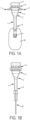
- FIG 1A is a front view
- FIG 1B is a side view illustrating the device of the present invention in the storage position.
- a device (1) for storing and dispensing a topical pharmaceutical liquid having a substantially rigid elongated container (2), configured to hold the liquid therein, having a proximal end (3) and a distal end (4) with respective openings and the distal end of the container tapering into an applicator tip, the distal opening being closed by a closure means (5) having lugs (34), the device also have an air valve (6), peripheral flanges (7) and cap (9).
- FIG 2A is a top view illustrating the valve of the present invention.
- the air valve (6) having peripheral flanges (7), a valve seat (8) and a cap (9).
- FIG 2B is a cross sectional view illustrating a valve of the present invention in the stored position.
- the air valve (6) having peripheral flanges (7), a valve seat (8) and a cap (9).
- the valve body having a top end (10) and a bottom end (11), wherein the valve body has a through bore (12) extending from the top end (10) to the bottom end (11) of the valve body.
- the valve seat (8) includes a resilient engaging means (13), the valve seat further comprises a cylindrical collar (14) projecting upwards from said valve seat along the periphery of the through bore opening and forming an extension of the through bore.
- a substantially rigid valve stem (15) having a top end (16) and a bottom end (17).
- the valve stem (15) further comprising a penetrating tip (18) at bottom end of the stem for puncturing the container seal (19) fused on the annular portion (21) of proximal end of the container (20).
- FIG 3A is a side view illustrating the device of the present invention in the dispensing position according to the invention.
- a device (1) for storing and dispensing a topical pharmaceutical liquid having a substantially rigid elongated container (2), configured to hold the liquid therein, having a proximal end (3) and a distal end (4) with respective openings and the distal end of the container tapering into an applicator tip (21), the proximal end having an air valve (6), having flanges (7) and cap (9).
- FIG 3B is a cross sectional view llustrating the valve of the present invention in the dispensing position according to the invention.
- the air valve (6) having peripheral flanges (7), a valve seat (8) and a cap (9).
- the valve body having a top end (10) and a bottom end (11), wherein the valve body has a through bore (12) extending from the top end (10) to the bottom end (11) of the valve body.
- the valve seat (8) includes a resilient engaging means (13), the valve seat further comprises a cylindrical collar (14) projecting upwards from said valve seat along the periphery of the through bore opening and forming an extension of the through bore.
- a substantially rigid valve stem (15) having a top end (16) and a bottom end (17).
- the valve stem (15) further comprising a penetrating tip (18) at bottom end of the stem which has punctured the container seal (19) fused on the annular portion (21) of proximal end of the container (20).
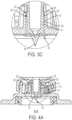
- FIG 3C is an enlarged cross sectional view illustrating a portion of the valve in the dispensing position, highlighted with broken circle D in Figure 3B according to the invention.
- the valve stem (15) has a means to form an airtight seal (22) against the inner wall (23) of the through bore (12).
- the valve stem (15) further comprising a penetrating tip (18) at bottom end of the stem which has punctured the container seal (19) to establish air communication where air can flow in the direction (24) through the valve between the interior of the container and the external enviorment.
- FIG 4A is a cross sectional view llustrating the valve in the sealed position according to the invention.
- the valve stem (15) has a penetrating tip (18) at bottom end of the stem which has punctured the container seal (19).
- the valve stem (15) has a seal (22) which forms an air-tight seal against the inner wall (23) of the through bore (12) to prohibit air communication through the valve between the interior of the container and the external enviorment.
- FIG 4B is an enlarged cross sectional view llustrating a portion of the valve in the sealed position, highlighted with broken circle C in Figure 4A according to the invention.
- the valve stem (15) has a penetrating tip (18) at bottom end of the stem which has punctured the container seal (19).
- the valve stem (15) has a seal (22) which forms an air-tight seal against the inner wall (23) of the through bore (12) to prohibit air communication through the valve between the interior of the container and the external enviorment.
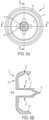
- FIG 5A is a bottom view llustrating the valve seat according to the invention.
- the bottom end of the valve body (11) has peripheral flanges (7) and a through bore (12) extending from the top end to the bottom end of the valve body.
- FIG 5B is a cross sectional side view illustrating the valve seat viewed through the plane B-B of Figure 5A .
- the valve seat (8) includes a resilient engaging means (13) having different heights, the valve seat further comprises a cylindrical collar (14) projecting upwards from said valve seat along the periphery of the through bore opening and forming an extension of the through bore (12).
- the through bore has annular seals (25) on its inner wall.
- FIG 5C is a top view illustrating the valve seat according to the invention and FIG 5D , 5E and 5F are different side views illustrating the valve seat of the invention.
- the valve seat includes a resilient engaging means (13) having different heights and peripheral flanges (7).
- the valve seat has a through bore (12).
- FIG 5G is a cross sectional side view illustrating the valve seat viewed through the plane A-A of Figure 5A .
- the valve seat (8) includes a resilient engaging means (13) having different heights, the valve seat further comprises a cylindrical collar (14) projecting upwards from said valve seat along the periphery of the through bore opening and forming an extension of the through bore (12).
- the through bore has seals (25) on its inner wall.
- FIG 6A is bottom view illustrating the cap according to the invention.
- the cap (9) has a side wall (27), wherein the side wall has resilient engaging means (28) for engaging the corresponding engaging means on the valve seat.
- the valve stem (15) has a penetrating tip (18) at bottom end of the stem.
- FIG 7A is cross sectional view of a portion of the container according to the invention.
- the elongated container (2) configured to hold the liquid therein, having a proximal end (3) and distal end (4) of the container tapering into an applicator tip (21).
- the proximal end of the container having an opening (29) and the distal opening of the container being closed by a closure means (5).
- FIG 7B is an enlargedview of a portion of Figure 7A highlighted with broken circle B according to the invention.
- the applicator tip (21) has a closure means (5) integrally moulded with the distal end of the applicator tip at a breakaway junction (31) situated in the recessed groove (32), so as to form an integral piece therewith, resulting in the break-away junction being recessed away from distal opening (33) of the container.
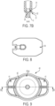
- FIG 8 is a side view of a lug according to the invention.
- the lug (34) can be attached to the break-away tip (not shown) to assist in manually removing the break-away tip.
- FIG 9 is a top view illustrating a valve of the present invention.
- the air valve (40) having peripheral flanges (41), a valve seat (42) and a cap (43a).
- FIG 10 is a cross sectional view illustrating the valve as viewed through the plane B-B of Figure 9 in the stored position.
- the air valve (40) having peripheral flanges (41), a valve seat (42) and a cap (43a).
- the valve body having a top end (43) and a bottom end (44), wherein the valve body has a through bore (45) extending from the top end (43) to the bottom end (44) of the valve body.
- the valve seat (42) includes a resilient engaging means (46), the valve seat further comprises a cylindrical collar (47) projecting upwards from said valve seat along the periphery of the through bore opening and forming an extension of the through bore.
- a substantially rigid valve stem (48) having a top end (49) and a bottom end (50).
- valve stem (48) further comprising a penetrating tip (51) at bottom end of the stem for pushing down on a protrusion (52) sticking out of the plane of the container seal (53) towards the penetrating tip so that pushing down of the penetrating tip on the protrusion, during dispensing, punctures the container seal (53) fused on the annular portion (54) of the proximal end of the container (20).
- FIG 11 is a cross sectional view illustrating the valve as viewed through the plane B-B of Figure 9 in the sealed position.
- the valve stem (48) has a penetrating tip (51) at bottom end of the stem which has punctured the container seal (53) (puncture not visible in this view).
- the top end of the valve stem (48) has a cap (43a).
- the resilient engaging means (46) engages the inside wall (61) of the cap (43a).
- a protrusion (52) sticking out of the plane of the container seal (53) towards the penetrating tip, the protrusion (52) is joined to the container seal (53) by means of a hinge (59) and a breakaway junction (58) which has been broken.
- the valve stem (48) has a seal (55) which forms an air-tight seal against the inner wall (56) of the through bore (45) to prohibit air communication through the valve between the interior of the container (57) and the external enviorment outside the container.
- FIG 12 is a cross sectional view illustrating the valve as viewed through the plane B-B of Figure 9 in the dispensing position.
- the air valve (40) having peripheral flanges (41), a valve seat (42) and a cap (43(a)).
- the valve body having a top end (43) and a bottom end (44), wherein the valve body has a through bore (45) extending from the top end (43) to the bottom end (44) of the valve body.
- the valve seat (42) includes a resilient engaging means (46) which engages the inside wall (61) of the cap (43a).
- the valve seat further comprises a cylindrical collar (47) projecting upwards from said valve seat along the periphery of the through bore opening and forming an extension of the through bore.
- a substantially rigid valve stem (48) having a top end (49) and a bottom end (50).
- the valve stem (48) further comprising a penetrating tip (51) at bottom end of the stem.
- the breakaway junction (58) which has been broken on the container seal (53) and the protrusion (not shown) is situated in the interior of the container (57).
- FIG 13 is a top view illustrating a valve seat according to the invention.
- the valve seat (42) includes resilient engaging means (46) having different heights.
- the valve seat has a through bore (45) extending from the top end (43) to the bottom end (not shown) of the valve seat.
- the end of the through bore (45) at the bottom end of the valve seat is sealed with a container seal (53).
- the annular portion of the valve seat (42) will be sealed to the proximal end of the container (not shown), when assembled.
- a protrusion (52) sticking out of the plane of the container seal (53).
- the protrusion (52) is joined to the container seal (53) by means of a breakaway junction (58) which has a hinge (59) on one point of attachment to the container seal (53).
- FIG 14 is a cross sectional side view illustrating a valve seat viewed through the plane A-A of Figure 13 according to the invention.
- the valve seat (42) includes resilient engaging means (46).
- the valve seat has a through bore (45) extending from the top end (43) to the bottom end (44) of the valve seat.
- the end of the through bore (45) at the bottom end of the valve seat is sealed with a container seal (53).
- the annular portion of the valve seat (42) will be sealed to the proximal end of the container (not shown), when assembled.
- In the centre of the container seal (53) is a protrusion (52) sticking out of the plane of the container seal (53).
- the protrusion (52) is joined to the container seal (53) by means of a breakaway junction (58) which has a hinge (59) on one point of attachment to the container seal (53).
- the valve seat (42) further comprises a cylindrical collar (47) projecting upwards from said valve seat along the periphery of the through bore opening and forming an extension of the through bore.
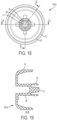
- FIG 15 is an enlarged view of a portion of Figure 14 highlighted with broken circle B according to the invention.
- the protrusion (52) is joined to the container seal (53) by means of a breakaway junction (58) which has a hinge (59) on one point of attachment to the container seal (53).
- FIG 16 is an enlargedview of a portion of Figure 14 highlighted with broken circle C according to the invention.
- the annular portion of the valve seat (42) will be sealed to the proximal end of the container (not shown), when assembled.
- FIG 17 is an enlargedview of a portion of Figure 14 highlighted with broken circle D according to the invention.
- the resilient engaging means (46) has an outward protrusion (60) meant to engage a resilient engaging means on the cap (not shown).
- FIG 18 is a bottom view illustrating a cap according to the invention.
- the cap (43a) has a side wall (61), wherein the side wall has resilient engaging means (62) for engaging the corresponding engaging means on the valve seat (not shown).
- the valve stem (48) has a penetrating tip (51) at bottom end of the stem and it has a radial seal (55) which forms an air-tight seal against the inner wall of the through bore when in the sealed position (not shown)
- FIG 19 is a cross sectional side view illustrating a valve seat viewed through the plane B-B of Figure 18 according to the invention.
- the cap (43a) has a side wall (61), wherein the side wall has resilient engaging means (55) which forms an air-tight seal against the inner wall (not shown) of the through bore (not shown), when in the sealing position.
- the valve stem (48) has a penetrating tip (51) at bottom end of the stem and it has a radial seal (not shown) which forms an air-tight seal against the inner wall of the through bore when in the sealed position (not shown).
- FIG 20 is a cross sectional side view illustrating a valve seat viewed through the plane A-A of Figure 18 according to the invention.
- the cap (43a) has a side wall (61), wherein the side wall has resilient engaging means (55) which forms an air-tight seal against the inner wall (not shown) of the through bore (not shown), when in the sealing position.
- the valve stem (48) has a penetrating tip (51) at bottom end of the stem and it has a radial seal (not shown) which forms an air-tight seal against the inner wall of the through bore when in the sealed position (not shown).
- FIG 21 is a front view of a lug according to the invention.
- the lug (63) can be attached to the break-away tip (not shown) to assist in manually removing the break-away tip.
- the lug (63) has a series of indentations (64) to assist in gripping the tug by the users fingers.
- FIG 22 is a side view of a lug according to the invention as illustrated in FIG. 21 .
- the lug (63) has a series of indentations (64) to assist in gripping the tug by the users fingers.
- FIG 23 is a cross sectional side view illustrating a lug viewed through the plane A-A of Figure 21 according to the invention.
- the lug has a breakaway junction (65) situated in the recessed groove (66).
- FIG 24 is a cross sectional side view illustrating a lug viewed through the plane C-C of Figure 21 according to the invention.
- The has a series of indentations (64) to assist in gripping the tug by the users fingers.
- FIG 25 is an enlargedview of a portion of Figure 23 highlighted with broken circle B according to the invention.
- the lug has a breakaway junction (65) situated in the recessed groove (66).
- a device having an elongated container defining an interior space and configured to hold the liquid therein, having a proximal end and a distal end with respective openings and a passage extending between the openings, the proximal opening being closed by a container seal and the distal end of the container tapering into an applicator tip which is integral therewith.
- the device has an air valvesealingly coupled to the proximal end of the container, wherein the air valve comprises a penetrating tip which can puncture the container seal, the valve being illustrated in a stored position in which the seal is not punctured by the penetrating tip.
- the air valve having a spring which biases the penetrating tip away from the container seal.
- the air valve also has a caphaving a top and side wall whose interior is of generally cylindrical configuration and of diameter slightly greater than the outside diameter of the proximal end of the container, the cap being sealingly coupled to the proximal end of the container and has an air inlet which opens and permits air communication to be formed when the top of cap is pressed towards the container.
- the distal opening of the container being closed at by a closure meanshaving lugs.
- a device having an elongated container defining an interior space and configured to hold the liquid therein, having a proximal end with an opening being closed by a container seal.
- the device has an air valve sealingly coupled to the proximal end of the container, wherein the air valve comprises a penetrating tip which can puncture the container seal, the valve being illustrated in a stored position in which the seal is not punctured by the penetrating tip.
- the air valve having a spring which biases the penetrating tip away from the container seal.
- the air valve also has a cap having a top and side wall whose interior is of generally cylindrical configuration and of diameter slightly greater than the outside diameter of the proximal end of the container, the cap has an air inletwhich opens and permits air communication to be formed when the top of cap is pressed towards the container.
- a device having an elongated container defining an interior space and configured to hold the liquid therein, having a proximal end with an opening being closed by a container seal.
- the device has an air valve sealingly coupled to the proximal end of the container, wherein the air valve comprises a penetrating tip which can puncture the container seal, the valve being illustrated in a stored position in which the seal is not punctured by the penetrating tip.
- the air valve having a spring which biases the penetrating tip away from the container seal.
- the air valve also has a cap having a top and side wall whose interior is of generally cylindrical configuration and of diameter slightly greater than the outside diameter of the proximal end of the container, the cap has an air inlet which opens and permits air communication to be formed when the top of cap is pressed towards the container.
- a device having an elongated container defining an interior space and configured to hold the liquid therein, having a proximal end with an opening being closed by a container seal and a distal end having an opening closed by a closure means having lugs.
- the device has an air valve coupled to the proximal end of the container.
- the air valve having a cap having a top and side wall slidingly coupled to the proximal end of the container. The valve being in a stored position in which the seal is not punctured by the penetrating tip.
- a spring sealing coupled to the proximal end of the container and made of resilient material which biases the penetrating tip away from the container seal, the spring having a penetrating tip in its interior.
- the spring whose interior is of generally cylindrical configuration and of diameter slightly greater than the outside diameter of the proximal end of the container and has an air inlet which opens and permits air communication to be formed when the top of cap is pressed towards the container.
- the spring has a penetrating tip (90) in its interior, protruding from its top which can puncture the container seal when the cap is pressed down in the direction towards the container seal.
- a device having an elongated container defining an interior space and configured to hold the liquid therein, having a proximal end with an opening being closed by a container seal.
- the device has an air valve coupled to the proximal end of the container.
- the air valve having a cap having a top and side wall slidingly coupled to the proximal end of the container.
- the cap has a penetrating tip in its interior, protruding from its top which can puncture the container seal when the cap is pressed down in the direction towards the container seal.
- the valve beingin a stored position in which the seal is not punctured by the penetrating tip.
- a spring sealing coupled to the proximal end of the container and coupled to the interior of the cap.
- the spring being made of resilient material which biases the cap and penetrating tip away from the container seal.
- the spring whose interior is of generally cylindrical configuration and of diameter slightly greater than the outside diameter of the proximal end of the container and has an air inlet which opens and permits air communication to be formed when the top of cap is pressed towards the container.
- a device for storing and dispensing a pharmaceutical liquid comprising: A) a substantially rigid elongated container defining an interior space and configured to hold the liquid therein, having a proximal end and a distal end with respective openings and a passage extending between the openings, the proximal opening being closed by a container seal and the distal end of the container tapering into an applicator tip which is integral therewith; and B) an air valve sealingly coupled to the proximal end of the container, wherein the air valve comprises a penetrating tip which can puncture the container seal to enabling air communication to be formed through the valve between the interior of the container and the external enviorment, the valve being positionable in a stored position in which the seal is not punctured by the penetrating tip, and in a dispensed position in which the seal is punctured by the penetrating tip and the air communication is formed, and in a sealed position in which the seal is punctured by the penet
- valve further comprises a spring which biases the penetrating tip away from the container seal.
- the engaging means of the valve seat also act as the spring which biases the penetrating tip away from the container seal.
- the air valve further comprises a cap having a top and side wall whose interior is of generally cylindrical configuration and of diameter slightly greater than the outside diameter of the proximal end of the container, said cap being sealingly coupled to the proximal end of the container and further comprises an air inlet which opens and permits air communication to be formed when the top of cap is pressed towards the container and which closes prohibiting air communication when the top of the cap moves away from the container.
- the air inlet is configured to open by elastically deforming to create a tear in the cap forming air communication when the cap is pressed and to close by self-reclosing to return opposite edges of said tear to a substantially contiguous closed condition prohibiting air communication when the cap is not pressed.
- a device wherein the cap is made of resilient material.
- a device wherein the penetrating tip is located in the interior of the cap extending generally axially from its top so that when the cap is pressed towards the container, the penetrating tip punctures the container seal.
- a device wherein the penetrating tip is coupled to the proximal end of the container situated in the interior of the cap so that when the cap is pressed towards the container, the penetrating tip moves towards the container causing it to puncture the container seal.
- the air valve further comprises a valve body having a top end and a bottom end, wherein the bottom end of the valve body and the proximal end of the container are sealingly coupled by an air tight connector, and the top end of the valve body has a valve seat, the valve body having a through bore extending from the top end to the bottom end of the valve body, wherein the through bore has an inner wall defining a passage through the valve body.
- the air valve further comprises a substantially rigid valve stem, wherein the penetrating tip is attached at one end of the valve stem and a cap is attached at the opposite end of the valve stem.
- valve stem is slidably receivable in the through bore and movable axially in the through bore towards and away from the outer surface of the container seal.
- valve seat further comprises a cylindrical collar projecting upwards from said valve seat along the periphery of the through bore opening and forming an extension of the through bore.
- valve stem and through bore have means to form an airtight seal with each other.
- a device wherein the inner wall of the through bore has a means to form an airtight seal against the valve stem.
- valve stem has a means to form an airtight seal against the inner wall of the through bore.
- the means to form an airtight seal between the valve stem and through bore comprises at least one annular ridge and at least one corresponding annular groove to sealably connect to the annular ridge.
- the means to form an airtight seal between the valve stem and through bore comprises a circumferential edge on the valve stem having a seal which can bear against a corresponding seal on the inner wall of the through bore to create an air-tight seal.
- a device wherein the interior of the container and the external enviorment are atabout atmospheric pressurewhen the valve is in the storage and dispensed position.
- the liquid is a topical veterinary liquid.
- a device wherein the liquid is for a pharmaceutically acceptable period of time.
- a device wherein the container is a prefilled disposable container.
- a device wherein the proximal end of the container is connected to the bottom of the valve by means of a snap fit connection or mechanical connection.
- the air tight connector is a sealing ring.
- a device wherein virtually all the liquid in the container is discharged through the applicator tip when the valve is in its dispensed position and the container is held in a near vertical orientation.
- a device wherein the outer edge of the container seal is fused or welded, to an adjacent annular portion of the container.
- a device wherein the container seal is configured to elastically distend to pass the penetrating tip through a tear in the container seal and to be self-reclosing by returning opposite edges of said tear to a substantially contiguous closed condition after withdrawal of the penetrating tip from the tear.
- a device wherein the applicator tip is selected from the group consisting of a dropper tip, a Uro-Jet tip, a needleless tip, a male Luer-Lock tip, a female Luer-Lock tip, an absorbent cotton tip, an absorbent band tip, an absorbent foam tip, a multi-hole distributor, or a brush tip.
- a device wherein the distal end of the container tapering into an applicator tip is an unobstructed opening of small size such that the liquid will not flow through by force of gravity when the applicator tip is directed downwardly and the container seal is not punctured by the penetrating tip or when the valve is in the sealed position.
- a device wherein the dispensing of the liquid through the applicator tip is under gravity flow and under atmospheric air pressure.
- a device wherein the device manually regulates and stops the gravity flow of liquid from the applicator tip when valve is in the sealed position.
- a device wherein the cap periphery is of resilient material.
- valve body has peripheral flanges to be used as grips for a user's index and middle finger.
- a device wherein the penetrating tip is moved towards the container seal to establish air communication between the container and the through bore.
- valve is a one-way valve permitting inflow of air through the valve into the container and prohibiting outflowof liquid out of the container through the valve, when the valve is in the dispense position.
- a device wherein the closure means is a break-away tip.
- valve stem having the penetrating tip is movable axially in the through bore away from the outer surface of the container seal once the seal is punctured.
- valve stem is slidably receivable in a through bore integrally formed in the valve body
- the through bore is in the form of a through tubular cylinder essentially perpendicular to the surface of the container seal.
- valve stem having the penetrating tip is movable axially in the through bore away from the outer surface of the container seal once the seal is punctured.
- the applicator tip has a proximal end near the distal end of the container and a distal end which is near the distal opening of the container having an annular recessed groove in the wall of the applicator, the break-away tip is integrally moulded with the distal end of the applicator tip at a breakaway junction situated in the recessed groove, so as to form an integral piece therewith, resulting in the break-away junction being recessed away from distal opening of the container.
- a device wherein the container is made from a polymer composition comprising a thermoplastic cyclic olefin polymer or copolymer and a thermoplastic elastomer.
- valve is made from a polymer composition comprising a thermoplastic cyclic olefin polymer or copolymer and a thermoplastic elastomer.
- a device wherein the container seal is made from a polymer composition comprising a thermoplastic cyclic olefin polymer or copolymer and a thermoplastic elastomer.
- a device wherein the container is made of a nor-bornene copolymer.
- a device wherein the valve is made of elastomeric materials.
- elastomeric materials that can be utilized include, but are not limited to, polyurethanes, polypropylene-EPDM, other polypropylenes, polysiloxane and/or silicone materials, butyl materials, isoprenes, neoprenes, polyethylenes and various copolymers, composites, blends or other combinations of such materials.
- plastics that can be utilized for valve stem and/or valve body include, but are not limited to, polyethylenes, polypropylenes, polycycloolefines, polyvinyl chlorides (PVC), polyamides (including aliphatic and aromatic variants), polyesters, polycarbonates, polyacrylates, polyurethanes, copolymers, blends, composites and combinations thereof.
- a device wherein the container seal is made of a barrier film is selected from the group consisting of a polyester film, a polyamide film, a polyvinylchloride film, a polychlorotrifluorethylene film. a halogenated polymer film, a non-halogenated polyisobutylene-isoprene rubberfilm, a polyvinylidene chloride film, a cyclic olefin copolymer film, a polypropylene film, a polyethylene film, a polytetrafluoroethylene film, a silicone oxide coated polymer film, an aluminum oxide coated polymer film, and combinations thereof.
- a device for storing and dispensing a topical pharmaceutical liquid comprising: A) a substantially rigid elongated container, configured to hold the liquid therein, having a proximal end and a distal end with respective openings and a passage extending between the openings, the proximal end of the container having an external radial surface, the proximal opening being closed by a container seal and the distal end of the container tapering into an applicator tip, the distal opening being closed by a closure means; and B) an air valve comprising (a) a valve body having a top end and a bottom end, wherein the bottom end of the valve body and the proximal end of the container are sealed together, wherein the valve body has peripheral flanges, wherein the top end of the valve body has a valve seat including an area defining a through bore extending from the top end to the bottom end of the valve body, wherein the through bore has an inner wall and has a seal protruding out
- a method of topically applying a pharmaceutical liquid to a patient using a device of the invention comprises: a) removing the closure means on the applicator tip; b) grasping the device in one hand by placing the index and middle finger on each of the flanges and a thumb on the cap; c) exerting pressure down on the cap to cause the penetrating tip to puncture the container seal to create an air communication between the through bore and the container, and permitting the inflow of air into the container resulting in dispensing of liquid through the applicator tip onto the patient; d) removing the exerted pressure from the cap so that the spring bias causes the penetrating tip to move in a direction away from the container seal and the seal on the valve stem bearing against the corresponding seal on the inner wall of the through bore to stop the air communication through the valve between the interior of the container and the external enviorment resulting in the stoppage of dispensing of liquid through the applicator tip onto the patient.
- a device for storing and dispensing a topical pharmaceutical liquid comprising: A) a substantially rigid elongated container, configured to hold the liquid therein, having a proximal end and a distal end with respective openings and a passage extending between the openings, the proximal end of the container having an external radial surface, the proximal opening being closed by a container seal and the distal end of the container tapering into an applicator tip, the distal opening being closed by a closure means; and B) an air valve comprising (a) a valve body having a top end and a bottom end, wherein the bottom end of the valve body comprises a container seal having a protrusion sticking out from the plane of the container seal; in the protrusion (52) is joined to the container seal by means of a hinge and a breakaway junction; and the bottom end of the valve body and the proximal end of the container are sealed together to form an air tight container, wherein the valve body has peripheral
- a device wherein the container seal compsises a protrusion joined to the container seal by means of a hinge and a breakaway junction, such that the break away junction breaks when the the penetrating tip pushes down on the protrusion, and the hinge enables the protrusion to remain joined to the seal; establishing air communication where air can flow through the valve between the interior of the container and the external enviorment.
Landscapes
- Health & Medical Sciences (AREA)
- Public Health (AREA)
- Veterinary Medicine (AREA)
- Life Sciences & Earth Sciences (AREA)
- Animal Behavior & Ethology (AREA)
- General Health & Medical Sciences (AREA)
- Engineering & Computer Science (AREA)
- Heart & Thoracic Surgery (AREA)
- Hematology (AREA)
- Anesthesiology (AREA)
- Biomedical Technology (AREA)
- Pharmacology & Pharmacy (AREA)
- Pulmonology (AREA)
- Mechanical Engineering (AREA)
- Ceramic Engineering (AREA)
- Containers And Packaging Bodies Having A Special Means To Remove Contents (AREA)
- Closures For Containers (AREA)
- Infusion, Injection, And Reservoir Apparatuses (AREA)
- Agricultural Chemicals And Associated Chemicals (AREA)
- Medical Preparation Storing Or Oral Administration Devices (AREA)
Claims (13)
- Dispositif (1) pour stocker et distribuer un liquide pharmaceutique comprenant :A) un récipient (2) allongé sensiblement rigide définissant un espace intérieur et configuré pour retenir le liquide dans celui-ci, ayant une extrémité proximale (3) et une extrémité distale (4) avec des ouvertures (29, 33) respectives et un passage s'étendant entre les ouvertures, l'ouverture proximale (29) étant fermée par un joint (19) de récipient et l'extrémité distale du récipient (4) se resserrant en une pointe d'applicateur (21) qui est d'un seul tenant avec celle-ci ; etB) une ventouse (6) accouplée avec scellement à l'extrémité proximale du récipient (3), caractérisé en ce que la ventouse (6) comprend une pointe pénétrante (18) qui peut percer le joint (19) de récipient pour permettre à une communication d'air d'être formée à travers la ventouse entre l'intérieur du récipient (2) et l'environnement externe, la ventouse étant positionnable dans une position stockée dans laquelle le joint (19) n'est pas percé par la pointe pénétrante (18), et dans une position distribuée dans laquelle le joint (19) est percé par la pointe pénétrante (18) et une communication d'air est formée, et dans une position scellée dans laquelle le joint (19) est percé par la pointe pénétrante (18) et un j oint étanche à l'air est formé pour empêcher une communication d'air d'être formée ; et dans lequel la distribution du liquide à travers la pointe d'applicateur (21) est régulée par la communication d'air.
- Dispositif (1) selon la revendication 1, dans lequel la ventouse comprend en outre un ressort qui écarte la pointe pénétrante (18) du joint (19) de récipient.
- Dispositif (1) selon la revendication 1, dans lequel la ventouse (6) comprend en outre un capuchon (9) ayant un dessus (26) et une paroi latérale (27) dont l'intérieur est de configuration généralement cylindrique et de diamètre légèrement supérieur au diamètre extérieur de l'extrémité proximale du récipient (3), ledit capuchon (9) étant accouplé avec scellement à l'extrémité proximale du récipient (3) et comprenant en outre une entrée d'air qui s'ouvre et permet à une communication d'air d'être formée lorsque le dessus du capuchon (9) est enfoncé vers le récipient (2) et qui se ferme en empêchant une communication d'air lorsque le dessus du capuchon (9) s'éloigne du récipient (2), dans lequel optionnellement :a) l'entrée d'air est configurée pour s'ouvrir en se déformant élastiquement pour créer une déchirure dans le capuchon (9) formant une communication d'air lorsque le capuchon (9) est enfoncé et pour se fermer en se refermant elle-même pour ramener les bords opposés de ladite déchirure à un état fermé sensiblement contigu, empêchant une communication d'air lorsque le capuchon (9) n'est pas enfoncé ; oub) la pointe pénétrante (18) se trouve à l'intérieur du capuchon (9) s'étendant généralement axialement à partir de son dessus de façon à ce que lorsque le capuchon (9) est enfoncé vers le récipient (2), la pointe pénétrante (18) perce le joint (19) de récipient ; ouc) la pointe pénétrante (18) est accouplée à l'extrémité proximale du récipient (3) située à l'intérieur du capuchon (9) de façon à ce que lorsque le capuchon (9) est enfoncé vers le récipient (2), la pointe pénétrante (18) se déplace vers le récipient (2), ce qui l'amène à percer le joint (19) de récipient.
- Dispositif (1) selon la revendication 1, dans lequel la ventouse (6) comprend en outre un corps de ventouse ayant une extrémité supérieure (10) et une extrémité inférieure (11), dans lequel l'extrémité inférieure du corps de ventouse (11) et l'extrémité proximale du récipient (3) sont accouplées avec scellement par un raccord étanche à l'air, et l'extrémité supérieure du corps de ventouse (10) a un siège de ventouse (8), le corps de ventouse ayant un alésage traversant (12) s'étendant de l'extrémité supérieure (10) à l'extrémité inférieure du corps de ventouse (11), dans lequel l'alésage traversant (12) a une paroi intérieure (23) définissant un passage à travers le corps de ventouse.
- Dispositif (1) selon la revendication 4, dans lequel la ventouse (6) comprend en outre une tige (15) de ventouse sensiblement rigide, dans lequel la pointe pénétrante (18) est fixée à une extrémité de la tige (15) de ventouse et un capuchon (9) est fixé à l'extrémité opposée de la tige (15) de ventouse.
- Dispositif (1) selon la revendication 5, dans lequel la tige (15) de ventouse peut être reçue de manière coulissante dans l'alésage traversant (12) et est mobile axialement dans l'alésage traversant (12) vers et à l'écart de la surface extérieure du joint (19) de récipient ; ou dans lequel la pointe pénétrante (18) est mobile perpendiculairement à la surface extérieure du joint (19) de récipient.
- Dispositif (1) selon la revendication 4, dans lequel le siège de ventouse (8) comprend en outre un collier cylindrique (14) faisant saillie vers le haut à partir dudit siège de ventouse (8) le long de la périphérie de l'ouverture de l'alésage traversant (12) et formant une extension de l'alésage traversant (12).
- Dispositif (1) selon la revendication 4, dans lequel la tige (15) de ventouse et l'alésage traversant (12) ont des moyens pour former un joint (22) étanche à l'air l'un avec l'autre.
- Dispositif (1) selon la revendication 4, dans lequel la paroi intérieure de l'alésage traversant (23) a un moyen pour former un joint (25) étanche à l'air contre la tige (15) de ventouse.
- Dispositif (1) selon la revendication 4, dans lequel la tige (15) de ventouse a un moyen pour former un joint (22) étanche à l'air contre la paroi intérieure de l'alésage traversant (23).
- Dispositif (1) selon la revendication 8, dans lequel le moyen pour former un joint (22) étanche à l'air entre la tige (15) de ventouse et l'alésage traversant (12) comprend au moins une crête annulaire et au moins une rainure annulaire correspondante pour être reliée avec scellement à la crête annulaire (25).
- Dispositif (1) selon la revendication 8, dans lequel le moyen pour former un joint (22) étanche à l'air entre la tige (15) de ventouse et l'alésage traversant (12) comprend un bord circonférentiel sur la tige (15) de ventouse ayant un joint (22) qui peut reposer contre un joint (25) correspondant sur la paroi intérieure de l'alésage traversant (23) pour créer un joint étanche à l'air.
- Dispositif (1) selon la revendication 1 dans lequel :a) l'extrémité proximale du récipient (3) allongé sensiblement rigide a une surface radiale externe ;b) l'ouverture distale (33) est fermée par un moyen de fermeture (5) ;c) la ventouse (6) comprend en outre :i) un corps de ventouse ayant une extrémité supérieure (10) et une extrémité inférieure (11), dans lequel l'extrémité inférieure du corps de ventouse (11) et l'extrémité proximale du récipient (3) sont scellées ensemble, dans lequel le corps de ventouse a des brides périphériques (7), dans lequel l'extrémité supérieure du corps de ventouse (10) a un siège de ventouse (8) comportant une zone définissant un alésage traversant (12) s'étendant de l'extrémité supérieure (10) à l'extrémité inférieure du corps de ventouse (11), dans lequel l'alésage traversant (12) a une paroi intérieure (23) et a un joint faisant saillie hors de ladite paroi intérieure (25), dans lequel le siège de ventouse (8) comporte un moyen de mise en prise (13) élastique, ledit moyen de mise en prise (13) faisant saillie vers le haut à partir dudit siège de ventouse (8) et étant de deux hauteurs différentes, dans lequel le siège de ventouse (8) comprend en outre un collier cylindrique (14) faisant saillie vers le haut à partir dudit siège de ventouse (8) le long de la périphérie de l'ouverture de l'alésage traversant (12) et formant une extension de l'alésage traversant (12) ;ii) une tige (15) de ventouse sensiblement rigide ayant une extrémité supérieure (16) et une extrémité inférieure (17), dans lequel la tige (15) est mobile dans l'alésage traversant (12) vers l'extrémité supérieure ou inférieure de l'alésage traversant (12), la tige (15) de ventouse a un bord circonférentiel et a un joint (22) sur ledit bord circonférentiel qui peut reposer contre un joint (25) correspondant sur la paroi intérieure de l'alésage traversant (23), la tige (15) de ventouse comprenant en outre une pointe pénétrante (18) à l'extrémité inférieure de la tige (17) pour percer le joint (19) de récipient lorsque la pointe pénétrante (18) est déplacée vers le joint (19) de récipient pour établir une communication d'air à travers la ventouse entre l'intérieur du récipient (2) et l'environnement externe ; etiii) un capuchon (9) à l'extrémité supérieure de la tige (16) ayant un dessus (26) et une paroi latérale (27), dans lequel la paroi latérale (27) a des moyens de mise en prise (28) élastiques pour mettre en prise les moyens de mise en prise correspondants sur le siège de ventouse (13) ;d) la ventouse a un ressort pour écarter la pointe pénétrante (18) du joint (19) de récipient ;e) la ventouse a une configuration qui est une position stockée, une position distribuée ou une position scellée, dans lequel :i) dans la position distribuée, la ventouse est configurée de sorte que la pointe pénétrante (18) perce le joint (19) de récipient et les joints sur la tige de ventouse (22) et la paroi intérieure de l'alésage traversant (25) ne créent pas de joint étanche à l'air, permettant à une communication d'air d'être formée à travers la ventouse entre l'intérieur du récipient (2) et l'environnement externe, ayant pour résultat que le liquide est distribué à partir du récipient (2) ;ii) dans la position scellée, la ventouse est configurée de sorte que la pointe pénétrante (18) se soit éloignée du récipient (2) et le joint sur la tige de ventouse (22) repose contre le joint (25) correspondant sur la paroi intérieure de l'alésage traversant (23) pour créer un joint étanche à l'air empêchant une communication d'air d'être formée à travers la ventouse entre l'intérieur du récipient (2) et l'environnement externe, ayant pour résultat qu'aucun liquide n'est distribué à partir du récipient (2) ; etiii) les moyens de mise en prise du capuchon (28) et le siège de ventouse (13) sont mis en prise l'un avec l'autre pour retenir la pointe pénétrante (18) en position lorsque la ventouse est dans la position stockée ou scellée ;f) la pointe d'applicateur (21) a une extrémité proximale proche de l'extrémité distale du récipient (4) et une extrémité distale qui est proche de l'ouverture distale du récipient (33) ayant une rainure encastrée (32) annulaire dans la paroi de l'applicateur ; etg) le moyen de fermeture (5) est une pointe rupturable moulée d'un seul tenant avec l'extrémité distale de la pointe d'applicateur (21) à une jonction rupturable (31) située dans la rainure encastrée (32), de manière à former une pièce d'un seul tenant avec celle-ci, ayant pour résultat que la jonction rupturable (31) est encastrée à l'écart de l'ouverture distale du récipient (33).
Applications Claiming Priority (2)
| Application Number | Priority Date | Filing Date | Title |
|---|---|---|---|
| US201562244616P | 2015-10-21 | 2015-10-21 | |
| PCT/US2016/058010 WO2017070408A1 (fr) | 2015-10-21 | 2016-10-21 | Dispositif de stockage et de distribution |
Publications (2)
| Publication Number | Publication Date |
|---|---|
| EP3365056A1 EP3365056A1 (fr) | 2018-08-29 |
| EP3365056B1 true EP3365056B1 (fr) | 2025-04-16 |
Family
ID=57396801
Family Applications (1)
| Application Number | Title | Priority Date | Filing Date |
|---|---|---|---|
| EP16801623.6A Active EP3365056B1 (fr) | 2015-10-21 | 2016-10-21 | Dispositif de stockage et de distribution |
Country Status (16)
| Country | Link |
|---|---|
| US (1) | US11291813B2 (fr) |
| EP (1) | EP3365056B1 (fr) |
| JP (1) | JP6846421B2 (fr) |
| KR (1) | KR102614204B1 (fr) |
| CN (2) | CN108290029B (fr) |
| AU (1) | AU2016340898B2 (fr) |
| CA (1) | CA3001871C (fr) |
| CL (1) | CL2018001024A1 (fr) |
| CO (1) | CO2018004170A2 (fr) |
| EA (1) | EA034159B1 (fr) |
| ES (1) | ES3033914T3 (fr) |
| HU (1) | HUE072372T2 (fr) |
| MX (1) | MX2018004873A (fr) |
| NZ (1) | NZ742416A (fr) |
| SA (1) | SA518391388B1 (fr) |
| WO (1) | WO2017070408A1 (fr) |
Families Citing this family (2)
| Publication number | Priority date | Publication date | Assignee | Title |
|---|---|---|---|---|
| BE1026856B1 (nl) * | 2018-12-10 | 2020-07-13 | Oystershell Nv | Medische inrichting voor topische behandelingen |
| US12366314B2 (en) | 2021-10-18 | 2025-07-22 | Colder Products Company | Fluid couplings |
Citations (2)
| Publication number | Priority date | Publication date | Assignee | Title |
|---|---|---|---|---|
| GB1444848A (en) * | 1974-08-29 | 1976-08-04 | Barnes Hind Diagnostics Inc | Plastics containers |
| US5638872A (en) * | 1995-08-22 | 1997-06-17 | National Safety Advisors, Inc. | Siphoning device for use in basting, measuring or immiscible liquid separation |
Family Cites Families (38)
| Publication number | Priority date | Publication date | Assignee | Title |
|---|---|---|---|---|
| US297174A (en) * | 1884-04-22 | Theodoee l | ||
| US2418036A (en) * | 1943-07-31 | 1947-03-25 | Edwin R Lane | Dispensing casing with valve operating means for a cartridge with a dispensing valve |
| AR205589A1 (es) * | 1974-10-09 | 1976-05-14 | Reckitt & Colmann Prod Ltd | Dispositivo introductor de una composicion acuosa en una cavidad corporal |
| WO1981002418A1 (fr) | 1980-02-27 | 1981-09-03 | W Christine | Organe de percage et valve combines pour sac flexible |
| GB2120630A (en) | 1982-05-21 | 1983-12-07 | Dey Lab Inc | Squeezable liquid-dispensing containers |
| GB2156949A (en) | 1984-03-31 | 1985-10-16 | William C Christine | Combined piercer and valve for flexible bag |
| DE8504383U1 (de) | 1985-02-16 | 1985-03-28 | Bayer Ag, 5090 Leverkusen | Tubenfoermiger Behaelter |
| US5042690A (en) * | 1990-02-08 | 1991-08-27 | Cp Packaging, Inc. | Unit dose assembly |
| US5433353A (en) * | 1991-11-21 | 1995-07-18 | Flinn; Christopher R. | Fluid storage and dispensing container having check valve |
| DK0988871T3 (da) * | 1991-12-18 | 2004-05-24 | Icu Medical Inc | Fremgangsmåde til overføring af fluid |
| US6164498A (en) * | 1999-09-01 | 2000-12-26 | Mcneil-Ppc. Inc. | Pump dispenser |
| US6343717B1 (en) * | 2000-11-21 | 2002-02-05 | Jack Yongfeng Zhang | Pre-filled disposable pipettes |
| US8105306B2 (en) * | 2002-10-03 | 2012-01-31 | 3M Innovative Properties Company | Skin antiseptic composition dispenser and methods of use |
| US20040186457A1 (en) * | 2003-03-17 | 2004-09-23 | Truitt Timothy Lee | Needleless access vial |
| WO2004096113A2 (fr) * | 2003-04-28 | 2004-11-11 | Medical Instill Technologies, Inc. | Contenant a ensemble soupape pour le remplissage et la distribution de substances, et dispositif et procede pour le remplissage |
| CN1845856A (zh) * | 2003-09-02 | 2006-10-11 | 大塚制药株式会社 | 排出构件、具有该排出构件的排出容器和点眼容器 |
| US7219816B1 (en) * | 2003-10-20 | 2007-05-22 | Amphastar Pharmaceuticals, Inc. | Easily sealed and opened pre-filled, disposable pipette |
| DE102004003439B4 (de) | 2004-01-22 | 2022-02-03 | Sata Gmbh & Co. Kg | Farbbechersystem für eine Farbspritzpistole |
| DE102004007733B4 (de) * | 2004-02-16 | 2014-02-13 | Sata Gmbh & Co. Kg | Fließbecher für eine Farbspritzpistole |
| DE202004004857U1 (de) | 2004-03-25 | 2004-05-27 | Klocke Verpackungs-Service Gmbh | Verpackung mit Applikator zum Auftragen von dünnflüssigen und pastösen Medien |
| WO2005094330A2 (fr) * | 2004-03-29 | 2005-10-13 | Merial Limited | Pipette/applicateur |
| US7204277B2 (en) * | 2004-09-16 | 2007-04-17 | B. Braun Medical Inc. | By-pass line connector for compounding system |
| US7810680B2 (en) | 2004-09-28 | 2010-10-12 | Stull Technologies, Inc. | Shock resistant break-off top |
| US7344267B2 (en) * | 2004-11-12 | 2008-03-18 | Michael Schrimmer | Illuminated toy balloon |
| US8109236B2 (en) * | 2007-04-05 | 2012-02-07 | Sumitomo Corporation Of America | Fluid delivery assembly |
| US20090013993A1 (en) * | 2007-06-29 | 2009-01-15 | Bird Healthcare Pty. Ltd. | Inhalation Device |
| US8272522B2 (en) | 2007-08-08 | 2012-09-25 | Stull Technologies, Inc. | Break-away impact-resistant tip |
| ES2511692T3 (es) * | 2007-09-11 | 2014-10-23 | Carmel Pharma Ab | Dispositivo de protección de elemento de perforación |
| GB2467174A (en) * | 2009-01-27 | 2010-07-28 | Daniel John Lantos | Bottle for beverages with air intake to prevent glugging |
| WO2011090454A1 (fr) * | 2009-06-25 | 2011-07-28 | Southers Erik L | Canette ayant un élément d'ouverture aux deux extrémités |
| US8945068B2 (en) * | 2011-02-22 | 2015-02-03 | Medtronic Minimed, Inc. | Fluid reservoir having a fluid delivery needle for a fluid infusion device |
| JP2014515950A (ja) * | 2011-05-06 | 2014-07-07 | サノフィ−アベンティス・ドイチュラント・ゲゼルシャフト・ミット・ベシュレンクテル・ハフツング | 薬物送達用の活性弁 |
| JP5783488B2 (ja) * | 2011-10-31 | 2015-09-24 | 株式会社吉野工業所 | 塗布容器 |
| FR2986703B1 (fr) * | 2012-02-09 | 2015-01-16 | Horus Pharma | Dispositif de conditionnement et de distribution d'un produit a usage ophtalmique |
| ES2656637T3 (es) * | 2012-02-28 | 2018-02-27 | Ge Healthcare As | Vial con válvula de flotador libre para productos farmacéuticos estériles |
| ES2863049T3 (es) * | 2012-11-26 | 2021-10-08 | Becton Dickinson Co | Válvula que permite mezcla en un dispositivo de suministro de fármacos |
| CN204280246U (zh) * | 2014-11-28 | 2015-04-22 | 湖南省农业信息与工程研究所 | 一种可重复使用配药储药密封桶 |
| CN104709604A (zh) * | 2015-03-12 | 2015-06-17 | 北京缘草堂生物科技开发有限公司 | 一种固体粉末药物喷瓶 |
-
2016
- 2016-10-21 ES ES16801623T patent/ES3033914T3/es active Active
- 2016-10-21 CA CA3001871A patent/CA3001871C/fr active Active
- 2016-10-21 AU AU2016340898A patent/AU2016340898B2/en active Active
- 2016-10-21 CN CN201680067838.XA patent/CN108290029B/zh active Active
- 2016-10-21 US US15/769,664 patent/US11291813B2/en active Active
- 2016-10-21 KR KR1020187014280A patent/KR102614204B1/ko active Active
- 2016-10-21 HU HUE16801623A patent/HUE072372T2/hu unknown
- 2016-10-21 EA EA201890988A patent/EA034159B1/ru unknown
- 2016-10-21 JP JP2018521076A patent/JP6846421B2/ja active Active
- 2016-10-21 MX MX2018004873A patent/MX2018004873A/es unknown
- 2016-10-21 WO PCT/US2016/058010 patent/WO2017070408A1/fr not_active Ceased
- 2016-10-21 CN CN202111133628.5A patent/CN113827854B/zh active Active
- 2016-10-21 NZ NZ742416A patent/NZ742416A/en unknown
- 2016-10-21 EP EP16801623.6A patent/EP3365056B1/fr active Active
-
2018
- 2018-04-18 SA SA518391388A patent/SA518391388B1/ar unknown
- 2018-04-19 CO CONC2018/0004170A patent/CO2018004170A2/es unknown
- 2018-04-20 CL CL2018001024A patent/CL2018001024A1/es unknown
Patent Citations (2)
| Publication number | Priority date | Publication date | Assignee | Title |
|---|---|---|---|---|
| GB1444848A (en) * | 1974-08-29 | 1976-08-04 | Barnes Hind Diagnostics Inc | Plastics containers |
| US5638872A (en) * | 1995-08-22 | 1997-06-17 | National Safety Advisors, Inc. | Siphoning device for use in basting, measuring or immiscible liquid separation |
Also Published As
| Publication number | Publication date |
|---|---|
| US20180304061A1 (en) | 2018-10-25 |
| JP6846421B2 (ja) | 2021-03-24 |
| CN113827854A (zh) | 2021-12-24 |
| EA034159B1 (ru) | 2020-01-13 |
| SA518391388B1 (ar) | 2022-06-22 |
| CN108290029B (zh) | 2021-09-03 |
| CA3001871C (fr) | 2023-12-05 |
| EP3365056A1 (fr) | 2018-08-29 |
| HUE072372T2 (hu) | 2025-11-28 |
| KR102614204B1 (ko) | 2023-12-14 |
| ES3033914T3 (en) | 2025-08-11 |
| CN108290029A (zh) | 2018-07-17 |
| AU2016340898A1 (en) | 2018-05-31 |
| NZ742416A (en) | 2019-03-29 |
| JP2018531715A (ja) | 2018-11-01 |
| MX2018004873A (es) | 2018-08-01 |
| CA3001871A1 (fr) | 2017-04-27 |
| CO2018004170A2 (es) | 2018-07-10 |
| KR20180074733A (ko) | 2018-07-03 |
| EA201890988A1 (ru) | 2018-11-30 |
| WO2017070408A1 (fr) | 2017-04-27 |
| AU2016340898B2 (en) | 2019-08-15 |
| CL2018001024A1 (es) | 2018-08-24 |
| CN113827854B (zh) | 2023-02-28 |
| US11291813B2 (en) | 2022-04-05 |
Similar Documents
| Publication | Publication Date | Title |
|---|---|---|
| US7798185B2 (en) | Dispenser and method for storing and dispensing sterile food product | |
| US7290573B2 (en) | Dispenser with sealed chamber, one-way valve and needle penetrable and laser resealable stopper | |
| HK1044298B (zh) | 药物分配器 | |
| US12296153B2 (en) | Method of sealing a syringe barrel | |
| WO2009064762A2 (fr) | Distributeur doseur de gel | |
| WO2013081699A2 (fr) | Couplage entéral femelle | |
| US6474508B1 (en) | Unit dose tube and cap assembly | |
| US11964134B2 (en) | Discharger with improved piercing tip | |
| EP3365056B1 (fr) | Dispositif de stockage et de distribution | |
| US11998651B2 (en) | Skin preparation applicator | |
| US20070225658A1 (en) | Unit Dose Delivery Systems | |
| HK1259644A1 (en) | Storage and dispenser device | |
| HK1259644B (en) | Storage and dispenser device | |
| US20260041856A1 (en) | Discharger with improved piercing tip | |
| GB2258618A (en) | Fluid medicament applicator |
Legal Events
| Date | Code | Title | Description |
|---|---|---|---|
| STAA | Information on the status of an ep patent application or granted ep patent |
Free format text: STATUS: UNKNOWN |
|
| STAA | Information on the status of an ep patent application or granted ep patent |
Free format text: STATUS: THE INTERNATIONAL PUBLICATION HAS BEEN MADE |
|
| PUAI | Public reference made under article 153(3) epc to a published international application that has entered the european phase |
Free format text: ORIGINAL CODE: 0009012 |
|
| STAA | Information on the status of an ep patent application or granted ep patent |
Free format text: STATUS: REQUEST FOR EXAMINATION WAS MADE |
|
| 17P | Request for examination filed |
Effective date: 20180521 |
|
| AK | Designated contracting states |
Kind code of ref document: A1 Designated state(s): AL AT BE BG CH CY CZ DE DK EE ES FI FR GB GR HR HU IE IS IT LI LT LU LV MC MK MT NL NO PL PT RO RS SE SI SK SM TR |
|
| AX | Request for extension of the european patent |
Extension state: BA ME |
|
| DAV | Request for validation of the european patent (deleted) | ||
| DAX | Request for extension of the european patent (deleted) | ||
| RAP1 | Party data changed (applicant data changed or rights of an application transferred) |
Owner name: BOEHRINGER INGELHEIM ANIMAL HEALTH USA INC. |
|
| REG | Reference to a national code |
Ref country code: HK Ref legal event code: DE Ref document number: 1259644 Country of ref document: HK |
|
| STAA | Information on the status of an ep patent application or granted ep patent |
Free format text: STATUS: EXAMINATION IS IN PROGRESS |
|
| 17Q | First examination report despatched |
Effective date: 20220921 |
|
| RAP1 | Party data changed (applicant data changed or rights of an application transferred) |
Owner name: BOEHRINGER INGELHEIM VETMEDICA GMBH |
|
| GRAP | Despatch of communication of intention to grant a patent |
Free format text: ORIGINAL CODE: EPIDOSNIGR1 |
|
| STAA | Information on the status of an ep patent application or granted ep patent |
Free format text: STATUS: GRANT OF PATENT IS INTENDED |
|
| INTG | Intention to grant announced |
Effective date: 20241129 |
|
| GRAS | Grant fee paid |
Free format text: ORIGINAL CODE: EPIDOSNIGR3 |
|
| GRAA | (expected) grant |
Free format text: ORIGINAL CODE: 0009210 |
|
| STAA | Information on the status of an ep patent application or granted ep patent |
Free format text: STATUS: THE PATENT HAS BEEN GRANTED |
|
| AK | Designated contracting states |
Kind code of ref document: B1 Designated state(s): AL AT BE BG CH CY CZ DE DK EE ES FI FR GB GR HR HU IE IS IT LI LT LU LV MC MK MT NL NO PL PT RO RS SE SI SK SM TR |
|
| REG | Reference to a national code |
Ref country code: GB Ref legal event code: FG4D |
|
| REG | Reference to a national code |
Ref country code: CH Ref legal event code: EP Ref country code: DE Ref legal event code: R096 Ref document number: 602016091926 Country of ref document: DE |
|
| REG | Reference to a national code |
Ref country code: IE Ref legal event code: FG4D |
|
| P01 | Opt-out of the competence of the unified patent court (upc) registered |
Free format text: CASE NUMBER: APP_16304/2025 Effective date: 20250403 |
|
| REG | Reference to a national code |
Ref country code: NL Ref legal event code: FP |
|
| REG | Reference to a national code |
Ref country code: ES Ref legal event code: FG2A Ref document number: 3033914 Country of ref document: ES Kind code of ref document: T3 Effective date: 20250811 |
|
| REG | Reference to a national code |
Ref country code: AT Ref legal event code: MK05 Ref document number: 1785146 Country of ref document: AT Kind code of ref document: T Effective date: 20250416 |
|
| PG25 | Lapsed in a contracting state [announced via postgrant information from national office to epo] |
Ref country code: FI Free format text: LAPSE BECAUSE OF FAILURE TO SUBMIT A TRANSLATION OF THE DESCRIPTION OR TO PAY THE FEE WITHIN THE PRESCRIBED TIME-LIMIT Effective date: 20250416 Ref country code: PT Free format text: LAPSE BECAUSE OF FAILURE TO SUBMIT A TRANSLATION OF THE DESCRIPTION OR TO PAY THE FEE WITHIN THE PRESCRIBED TIME-LIMIT Effective date: 20250818 |
|
| REG | Reference to a national code |
Ref country code: LT Ref legal event code: MG9D |
|
| PG25 | Lapsed in a contracting state [announced via postgrant information from national office to epo] |
Ref country code: GR Free format text: LAPSE BECAUSE OF FAILURE TO SUBMIT A TRANSLATION OF THE DESCRIPTION OR TO PAY THE FEE WITHIN THE PRESCRIBED TIME-LIMIT Effective date: 20250717 Ref country code: NO Free format text: LAPSE BECAUSE OF FAILURE TO SUBMIT A TRANSLATION OF THE DESCRIPTION OR TO PAY THE FEE WITHIN THE PRESCRIBED TIME-LIMIT Effective date: 20250716 |
|
| PG25 | Lapsed in a contracting state [announced via postgrant information from national office to epo] |
Ref country code: PL Free format text: LAPSE BECAUSE OF FAILURE TO SUBMIT A TRANSLATION OF THE DESCRIPTION OR TO PAY THE FEE WITHIN THE PRESCRIBED TIME-LIMIT Effective date: 20250416 |
|
| PG25 | Lapsed in a contracting state [announced via postgrant information from national office to epo] |
Ref country code: BG Free format text: LAPSE BECAUSE OF FAILURE TO SUBMIT A TRANSLATION OF THE DESCRIPTION OR TO PAY THE FEE WITHIN THE PRESCRIBED TIME-LIMIT Effective date: 20250416 |
|
| PG25 | Lapsed in a contracting state [announced via postgrant information from national office to epo] |
Ref country code: HR Free format text: LAPSE BECAUSE OF FAILURE TO SUBMIT A TRANSLATION OF THE DESCRIPTION OR TO PAY THE FEE WITHIN THE PRESCRIBED TIME-LIMIT Effective date: 20250416 |
|
| PG25 | Lapsed in a contracting state [announced via postgrant information from national office to epo] |
Ref country code: AT Free format text: LAPSE BECAUSE OF FAILURE TO SUBMIT A TRANSLATION OF THE DESCRIPTION OR TO PAY THE FEE WITHIN THE PRESCRIBED TIME-LIMIT Effective date: 20250416 |
|
| PG25 | Lapsed in a contracting state [announced via postgrant information from national office to epo] |
Ref country code: RS Free format text: LAPSE BECAUSE OF FAILURE TO SUBMIT A TRANSLATION OF THE DESCRIPTION OR TO PAY THE FEE WITHIN THE PRESCRIBED TIME-LIMIT Effective date: 20250716 |
|
| PG25 | Lapsed in a contracting state [announced via postgrant information from national office to epo] |
Ref country code: IS Free format text: LAPSE BECAUSE OF FAILURE TO SUBMIT A TRANSLATION OF THE DESCRIPTION OR TO PAY THE FEE WITHIN THE PRESCRIBED TIME-LIMIT Effective date: 20250816 |
|
| PG25 | Lapsed in a contracting state [announced via postgrant information from national office to epo] |
Ref country code: LV Free format text: LAPSE BECAUSE OF FAILURE TO SUBMIT A TRANSLATION OF THE DESCRIPTION OR TO PAY THE FEE WITHIN THE PRESCRIBED TIME-LIMIT Effective date: 20250416 |
|
| REG | Reference to a national code |
Ref country code: CH Ref legal event code: U11 Free format text: ST27 STATUS EVENT CODE: U-0-0-U10-U11 (AS PROVIDED BY THE NATIONAL OFFICE) Effective date: 20251101 |
|
| PGFP | Annual fee paid to national office [announced via postgrant information from national office to epo] |
Ref country code: NL Payment date: 20251021 Year of fee payment: 10 |
|
| REG | Reference to a national code |
Ref country code: HU Ref legal event code: AG4A Ref document number: E072372 Country of ref document: HU |
|
| PGFP | Annual fee paid to national office [announced via postgrant information from national office to epo] |
Ref country code: HU Payment date: 20251103 Year of fee payment: 10 |
|
| PGFP | Annual fee paid to national office [announced via postgrant information from national office to epo] |
Ref country code: DE Payment date: 20251021 Year of fee payment: 10 |
|
| PGFP | Annual fee paid to national office [announced via postgrant information from national office to epo] |
Ref country code: GB Payment date: 20251022 Year of fee payment: 10 |
|
| PG25 | Lapsed in a contracting state [announced via postgrant information from national office to epo] |
Ref country code: SM Free format text: LAPSE BECAUSE OF FAILURE TO SUBMIT A TRANSLATION OF THE DESCRIPTION OR TO PAY THE FEE WITHIN THE PRESCRIBED TIME-LIMIT Effective date: 20250416 Ref country code: DK Free format text: LAPSE BECAUSE OF FAILURE TO SUBMIT A TRANSLATION OF THE DESCRIPTION OR TO PAY THE FEE WITHIN THE PRESCRIBED TIME-LIMIT Effective date: 20250416 |
|
| PGFP | Annual fee paid to national office [announced via postgrant information from national office to epo] |
Ref country code: IT Payment date: 20251024 Year of fee payment: 10 |
|
| PGFP | Annual fee paid to national office [announced via postgrant information from national office to epo] |
Ref country code: FR Payment date: 20251030 Year of fee payment: 10 |
|
| PGFP | Annual fee paid to national office [announced via postgrant information from national office to epo] |
Ref country code: CH Payment date: 20251101 Year of fee payment: 10 |
|
| REG | Reference to a national code |
Ref country code: DE Ref legal event code: R097 Ref document number: 602016091926 Country of ref document: DE |
|
| PG25 | Lapsed in a contracting state [announced via postgrant information from national office to epo] |
Ref country code: CZ Free format text: LAPSE BECAUSE OF FAILURE TO SUBMIT A TRANSLATION OF THE DESCRIPTION OR TO PAY THE FEE WITHIN THE PRESCRIBED TIME-LIMIT Effective date: 20250416 |
|
| PG25 | Lapsed in a contracting state [announced via postgrant information from national office to epo] |
Ref country code: EE Free format text: LAPSE BECAUSE OF FAILURE TO SUBMIT A TRANSLATION OF THE DESCRIPTION OR TO PAY THE FEE WITHIN THE PRESCRIBED TIME-LIMIT Effective date: 20250416 |
|
| PG25 | Lapsed in a contracting state [announced via postgrant information from national office to epo] |
Ref country code: SK Free format text: LAPSE BECAUSE OF FAILURE TO SUBMIT A TRANSLATION OF THE DESCRIPTION OR TO PAY THE FEE WITHIN THE PRESCRIBED TIME-LIMIT Effective date: 20250416 Ref country code: RO Free format text: LAPSE BECAUSE OF FAILURE TO SUBMIT A TRANSLATION OF THE DESCRIPTION OR TO PAY THE FEE WITHIN THE PRESCRIBED TIME-LIMIT Effective date: 20250416 |
|
| PGFP | Annual fee paid to national office [announced via postgrant information from national office to epo] |
Ref country code: ES Payment date: 20251216 Year of fee payment: 10 |
|
| PLBE | No opposition filed within time limit |
Free format text: ORIGINAL CODE: 0009261 |
|
| STAA | Information on the status of an ep patent application or granted ep patent |
Free format text: STATUS: NO OPPOSITION FILED WITHIN TIME LIMIT |
|
| REG | Reference to a national code |
Ref country code: CH Ref legal event code: L10 Free format text: ST27 STATUS EVENT CODE: U-0-0-L10-L00 (AS PROVIDED BY THE NATIONAL OFFICE) Effective date: 20260225 |
|
| 26N | No opposition filed |
Effective date: 20260119 |