EP3365143B1 - Robot et système de commande de robot - Google Patents
Robot et système de commande de robot Download PDFInfo
- Publication number
- EP3365143B1 EP3365143B1 EP16858265.8A EP16858265A EP3365143B1 EP 3365143 B1 EP3365143 B1 EP 3365143B1 EP 16858265 A EP16858265 A EP 16858265A EP 3365143 B1 EP3365143 B1 EP 3365143B1
- Authority
- EP
- European Patent Office
- Prior art keywords
- actuator
- vehicle
- outrigger
- controller
- robot
- Prior art date
- Legal status (The legal status is an assumption and is not a legal conclusion. Google has not performed a legal analysis and makes no representation as to the accuracy of the status listed.)
- Active
Links
Images








Classifications
-
- B—PERFORMING OPERATIONS; TRANSPORTING
- B25—HAND TOOLS; PORTABLE POWER-DRIVEN TOOLS; MANIPULATORS
- B25J—MANIPULATORS; CHAMBERS PROVIDED WITH MANIPULATION DEVICES
- B25J11/00—Manipulators not otherwise provided for
-
- B—PERFORMING OPERATIONS; TRANSPORTING
- B25—HAND TOOLS; PORTABLE POWER-DRIVEN TOOLS; MANIPULATORS
- B25J—MANIPULATORS; CHAMBERS PROVIDED WITH MANIPULATION DEVICES
- B25J9/00—Program-controlled manipulators
- B25J9/10—Program-controlled manipulators characterised by positioning means for manipulator elements
- B25J9/104—Program-controlled manipulators characterised by positioning means for manipulator elements with cables, chains or ribbons
-
- B—PERFORMING OPERATIONS; TRANSPORTING
- B25—HAND TOOLS; PORTABLE POWER-DRIVEN TOOLS; MANIPULATORS
- B25J—MANIPULATORS; CHAMBERS PROVIDED WITH MANIPULATION DEVICES
- B25J11/00—Manipulators not otherwise provided for
- B25J11/008—Manipulators for service tasks
-
- B—PERFORMING OPERATIONS; TRANSPORTING
- B25—HAND TOOLS; PORTABLE POWER-DRIVEN TOOLS; MANIPULATORS
- B25J—MANIPULATORS; CHAMBERS PROVIDED WITH MANIPULATION DEVICES
- B25J13/00—Controls for manipulators
- B25J13/08—Controls for manipulators by means of sensing devices, e.g. viewing or touching devices
-
- B—PERFORMING OPERATIONS; TRANSPORTING
- B25—HAND TOOLS; PORTABLE POWER-DRIVEN TOOLS; MANIPULATORS
- B25J—MANIPULATORS; CHAMBERS PROVIDED WITH MANIPULATION DEVICES
- B25J19/00—Accessories fitted to manipulators, e.g. for monitoring, for viewing; Safety devices combined with or specially adapted for use in connection with manipulators
- B25J19/02—Sensing devices
-
- B—PERFORMING OPERATIONS; TRANSPORTING
- B25—HAND TOOLS; PORTABLE POWER-DRIVEN TOOLS; MANIPULATORS
- B25J—MANIPULATORS; CHAMBERS PROVIDED WITH MANIPULATION DEVICES
- B25J19/00—Accessories fitted to manipulators, e.g. for monitoring, for viewing; Safety devices combined with or specially adapted for use in connection with manipulators
- B25J19/02—Sensing devices
- B25J19/021—Optical sensing devices
- B25J19/023—Optical sensing devices including video camera means
-
- B—PERFORMING OPERATIONS; TRANSPORTING
- B25—HAND TOOLS; PORTABLE POWER-DRIVEN TOOLS; MANIPULATORS
- B25J—MANIPULATORS; CHAMBERS PROVIDED WITH MANIPULATION DEVICES
- B25J9/00—Program-controlled manipulators
- B25J9/0009—Constructional details, e.g. manipulator supports, bases
- B25J9/0015—Flexure members, i.e. parts of manipulators having a narrowed section allowing articulation by flexion
-
- B—PERFORMING OPERATIONS; TRANSPORTING
- B25—HAND TOOLS; PORTABLE POWER-DRIVEN TOOLS; MANIPULATORS
- B25J—MANIPULATORS; CHAMBERS PROVIDED WITH MANIPULATION DEVICES
- B25J9/00—Program-controlled manipulators
- B25J9/0084—Program-controlled manipulators comprising a plurality of manipulators
- B25J9/0087—Dual arms
-
- B—PERFORMING OPERATIONS; TRANSPORTING
- B25—HAND TOOLS; PORTABLE POWER-DRIVEN TOOLS; MANIPULATORS
- B25J—MANIPULATORS; CHAMBERS PROVIDED WITH MANIPULATION DEVICES
- B25J9/00—Program-controlled manipulators
- B25J9/16—Program controls
- B25J9/1679—Program controls characterised by the tasks executed
- B25J9/1682—Dual arm manipulator; Coordination of several manipulators
-
- G—PHYSICS
- G05—CONTROLLING; REGULATING
- G05D—SYSTEMS FOR CONTROLLING OR REGULATING NON-ELECTRIC VARIABLES
- G05D1/00—Control of position, course, altitude or attitude of land, water, air or space vehicles, e.g. using automatic pilots
- G05D1/02—Control of position or course in two dimensions
- G05D1/021—Control of position or course in two dimensions specially adapted to land vehicles
- G05D1/0276—Control of position or course in two dimensions specially adapted to land vehicles using signals provided by a source external to the vehicle
- G05D1/0278—Control of position or course in two dimensions specially adapted to land vehicles using signals provided by a source external to the vehicle using satellite positioning signals, e.g. GPS
-
- G—PHYSICS
- G06—COMPUTING OR CALCULATING; COUNTING
- G06V—IMAGE OR VIDEO RECOGNITION OR UNDERSTANDING
- G06V20/00—Scenes; Scene-specific elements
- G06V20/10—Terrestrial scenes
-
- G—PHYSICS
- G06—COMPUTING OR CALCULATING; COUNTING
- G06V—IMAGE OR VIDEO RECOGNITION OR UNDERSTANDING
- G06V20/00—Scenes; Scene-specific elements
- G06V20/50—Context or environment of the image
- G06V20/56—Context or environment of the image exterior to a vehicle by using sensors mounted on the vehicle
- G06V20/58—Recognition of moving objects or obstacles, e.g. vehicles or pedestrians; Recognition of traffic objects, e.g. traffic signs, traffic lights or roads
Definitions
- Vehicles include multiple systems such as propulsion, steering, braking, etc.
- prototype vehicles are tested to assess performance of the vehicle. For instance road tests are conducted to assess vehicle speed, maneuverability, responsiveness, etc. During testing, data is acquired to evaluate performance of the vehicle. Vehicle design may then be changed or tuned to improve performance.
- the present disclosure describes embodiments that relate to a robot and robot control system.
- the invention refers to a system according to claim 1.
- the present disclosure describes a robot configured to drive a vehicle.
- the robot includes: (i) an accelerator actuator configured to operate an accelerator operator of the vehicle; (ii) an arm configured to steer the vehicle; (iii) an actuator coupled to the arm via a link; and (iv) a controller.
- the controller is configured to, in response to an accelerator command, send a first signal to the accelerator actuator to operate the accelerator operator.
- the controller is also configured to, in response to a steering command, send a second signal to the actuator, thereby causing the actuator to apply a particular torque to the link so as to steer the vehicle.
- the present disclosure describes a system.
- the system includes a vehicle.
- the vehicle includes an accelerator operator and a steering operator.
- the system also includes a robot.
- the robot includes: (i) an accelerator actuator coupled to the accelerator operator of the vehicle and configured to operate the accelerator operator, and (ii) a steering actuator coupled to the steering operator of the vehicle and configured to operate the steering operator.
- the system also includes at least one outrigger coupled to the vehicle or the robot and configured to be in either an undeployed state or a deployed state, where in the deployed state, the outrigger is configured to engage a surface when the vehicle is at a predetermined lean angle to laterally stabilize the vehicle.
- the system further includes an outrigger actuator configured to switch the outrigger from the undeployed state to the deployed state.
- the present disclosure describes a steering system.
- the steering system includes a robot.
- the robot includes: (i) a first arm and a second arm, and (ii) an actuator coupled to the first arm via a first link and coupled to the second arm via a second link.
- the steering system also includes a vehicle.
- the vehicle includes: a handlebar.
- the first arm is coupled to a first end of the handlebar and the second arm is coupled to a second end of the handlebar, such that position of the actuator determines an angle of the handlebar, thereby determining corresponding steering angle of the vehicle.
- a robot may ride along with the human driver in the vehicle, and the robot may be equipped with sensors and cameras configured to monitor the human driver.
- the vehicle may include autonomous control systems configured to operate the vehicle during testing. These systems may be beneficial in conducting destructive tests, for example, to avoid any likelihood of injuring a human driver.
- data associated with monitoring and evaluating the driver is not available.
- a human-mimicking robot is avoiding costly modification to the vehicle. Similar to a human driver, the robot may be configured to operate existing vehicle systems such as accelerator pedal, brakes, steering wheel with little or no modification to these systems. A further advantage of using such a human-mimicking robot is to automate transportation with little or no modification to the vehicle.
- a vehicle could be a mobile machine that can be used to transport a person, people, or cargo. Any vehicle discussed herein can be driven and/or otherwise guided along a path on land, in water, on water, or in the air or outer space.
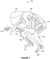
- FIG. 1 illustrates a perspective view of a robot 100, in accordance with an example implementation.
- the robot 100 is a humanoid or human-mimicking robot and may be configured as a rider of a vehicle.
- a motorcycle is used as an example vehicle, but the robot 100 may be configured to ride other vehicle types.
- the robot 100 is shown in Figure 1 in a driving position of a motorcycle.
- the robot 100 includes a main body 102, left leg 104, right leg 106, left foot 108, right foot 110, left arm 112, right arm 114, left hand 1 16, right hand 118, and a head 120.
- the main body 102 is adapted to confirm to a driver's seat of a motorcycle as shown and described below with respect to Figure 2 .
- the left and right legs 104 and 106, the left and right arms 112 and 114, and the head 120 are connected to the main body 102.
- FIG. 2 illustrates a side view of the robot 100 riding a motorcycle 200, in accordance with an example implementation.
- the motorcycle 200 includes a rear wheel 202, a front wheel 204, and a vehicle body 206.
- An engine 208 is mounted to or within the vehicle body 206 and is configured to power the motorcycle 200.
- a fuel tank 210 is mounted above the engine 208, and a driver's seat 212 is disposed at a rear end of the fuel tank 210.
- FIG 3A illustrates a schematic diagram showing a configuration of a robot control system 300, in accordance with an example implementation.
- the robot 100 includes a body frame 302 disposed within the main body 102 shown in Figures 1 and 2 .
- a control unit 304 and a battery 306 are mounted to the body frame 302.
- the battery 306 provides electric power to various systems of the robot 100 such as the control unit 304, sensors, etc.
- the motorcycle 200 includes a handlebar 308 configured to operate as steering member for the motorcycle 200.
- the handlebar 308 is rotatable around a steering shaft 310. By pivoting the handlebar 308 left and right about the steering shaft 310, the front wheel 204 of the motorcycle 200 is rotated to the left and right.
- a position sensor 312 is mounted to the handlebar 308 or the steering shaft 310. In other examples, the position sensor 312 could be mounted on a steering actuator 322 instead of on the handlebar 308 or the steering shaft 310.
- the position sensor 312 is configured to detect a steering angle of the handlebar 308, and provide a detection signal indicating the steering angle of the handlebar 308 to the control unit 304.
- the accelerator 314 is attached to the handlebar 308.
- the accelerator 314 includes an accelerator grip that is rotatable by the right hand 118 of the robot 100 to vary a throttle opening of the engine 208.
- the motorcycle 200 also includes a left grip 316 mounted on the left side of the handlebar 308, and the left hand 116 of the robot 100 is configured to grip the left grip 316.
- the robot 100 has an accelerator actuator 318 mounted or coupled to the right hand 118.
- the accelerator actuator 318 may include, for example, an electric motor configured to operate the accelerator 314 based on a first driving signal input from the control unit 304. For instance, in response to the first driving signal, the accelerator actuator 318 may be configured to rotate the accelerator 314 in a clockwise direction or a counter-clockwise direction.
- Rotating the accelerator 314 in one direction about a longitudinal axis of the accelerator grip may correspond to opening the throttle of the engine 208, whereas rotating the accelerator 314 in the other direction may correspond to closing the throttle of the engine 208, or vice versa.
- rotational speed of the engine 208 increases, and in response to rotating the accelerator 314 in a direction corresponding to closing the throttle, rotational speed of the engine 208 decreases. If no signal is provided to the accelerator actuator 318, the accelerator 314 returns to a neutral state that corresponds to a fully closed position of the throttle.
- the accelerator actuator 318 includes a position sensor 320 configured to detect rotational position of the accelerator 314, and output a detection signal indicating the rotational position of the accelerator 314 to the control unit 304.
- the control unit 304 may thus use this signal to implement a closed-loop feedback control of the rotational position of the accelerator 314, and thus the speed of the motorcycle 200.
- the right hand 118 is attached to a distal end of the right arm 114 and the left hand 116 is attached to a distal end of the left arm 112.
- the left and right arms 112 and 114 are connected to the body frame 302 via the steering actuator 322 (e.g., a rotary actuator 508 described below).
- the steering actuator 322 may include, for example, an electric motor configured to rotate the left and right arms 112 and 114 to the left and right directions and apply a torque thereto in response to a second driving signal input from the control unit 304.
- the handlebar 308 By rotating the left and right arms 112 and 114 to pivot to the left, the handlebar 308 is turned to the left, and the motorcycle 200 turns to the left. By rotating the left and right arms 112 and 114 to pivot to the right, the handlebar 308 is turned to the right, and the motorcycle 200 turns to the right.
- the steering actuator 322 may include a torque sensor 324.
- the torque sensor 324 may be configured to detect a torque applied to the left and right arms 112 and 114 and output a detection signal indicating the torque applied to the left and right arms 112 and 114 to the control unit 304.
- the control unit 304 may then use this signal to implement a closed-loop feedback control of the steering actuator 322 such that the steering actuator 322 applies a particular torque to the arms 112 and 114, and thus controls the steering angle or the lean angle of the motorcycle 200.
- An example steering mechanism and control system are described below with respect to Figures 5A-5B .
- the robot 100 may further include a first brake actuator 326 coupled to a first brake operator 328 of the motorcycle 200.
- the first brake operator 328 may be a brake lever disposed in front of the accelerator 314.
- the first brake actuator 326 may include, for example, an electric motor coupled to the right arm 114.
- other actuator types could be used such as hydraulic or pneumatic cylinders.
- the first brake actuator 326 could be connected to the first brake operator 328 through a link member 330.
- the link member 330 may include a wire or string (e.g., the twisted string 606 described below with respect to Figures 6A-6B ) attached to the first brake operator 328.
- the first brake actuator 326 may be configured to operate the first brake operator 328 in response to a third driving signal input from the control unit 304.
- the first brake actuator 326 may move the first brake operator 328 in a braking direction (e.g., inward toward the robot 100) or a non-braking direction (e.g., outward away from the robot 100) in response to the third driving signal input from the control unit 304.
- the braking force applied by front brakes of the motorcycle 200 is increased.
- the braking force applied by the front brakes is reduced.
- the first brake actuator 326 may include a torque sensor 332.
- the torque sensor 332 may be configured to detect a torque applied to a first brake operator 328 and output a detection signal to the control unit 304. Based on the torque detection signal from the torque sensor 332, the control unit 304 provides a signal to a mechanism integrated into the right hand 118 of the robot 100 and configured to move or apply the front brakes.
- the higher the torque applied to the first brake operator 328 the higher the braking force to be applied by the front brakes and vice versa.
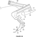
- Figure 3B illustrates zoomed-in side view of the left foot 108 and the left leg 104, in accordance with an example implementation.
- the locking member 336 has a recess 340.
- the locking member 336 is arranged such that the operator 338 is sandwiched by or within the recess 340.
- the shift operator 338 rotates counter-clockwise from a perspective of a viewer of Figures 3A-3B (i.e., the shift operator 338 is depressed downwardly) by the left foot 108.
- the transmission shins down, i.e., shifts to a gear with a higher gear ratio.
- the shift actuator 342 extends, the shift operator 338 rotates clockwise (i.e., moves upward) by the left foot 108, thus causing the transmission to shift up, i.e., shift to a gear with a smaller gear ratio.
- the operation direction of the shift operator 338 for shifting up and shifting down is not limited to these directions.
- the shift actuator 342 may include a position sensor 344 configured to detect position of the shift operator 338 or the shift actuator 342.
- the position sensor 344 outputs a detection signal indicating the position of the shift operator 338 to the control unit 304.
- the control unit 304 may use this signal to control the position of the shift operator 338, and thus control the transmission ratio at which the motorcycle 200 operates.
- the clutch actuator 346 is configured to operate the clutch operator 348 based on a fifth driving signal input from the control unit 304. Specifically, the clutch actuator 346 moves the clutch operator 348 to a clutch disengagement or engagement position based on the fifth driving signal input from the control unit 304.
- the clutch operator 348 When the clutch operator 348 is moved to the disengagement position (e.g., pulled inward toward the robot 100), the clutch of the transmission is disengaged. When the clutch operator 348 is moved to the engagement position (e.g., released away from the robot 100), the clutch of the transmission is engaged. Further, when the clutch operator 348 is between a fully engaged position and a fully disengaged position, the clutch is in a partially engaged state.
- the clutch actuator 346 may have a position sensor 352 configured to detect the operating position of the clutch operator 348.
- the position sensor 352 is configured to output a detection signal indicating the position of the clutch operator 348 to the control unit 304.
- the control unit 304 may use this signal to control the position of the clutch operator 348, and thus control the engagement and disengagement of the transmission clutch.
- the right foot 110 is coupled to the distal end of the right leg 106.
- the right foot 110 is rotatably coupled to the right leg 106 and is configured to pivot about an ankle 354.
- the right foot 110 is configured to operate a second brake operator 356 (e.g., rear-brake pedal) of the motorcycle 200.
- the robot 100 may have a second brake actuator 358 that is coupled to the right leg 106 and is configured to operate the second brake operator 356 via the right foot 110.
- the second brake actuator 358 could be, for example, a hydraulic or pneumatic cylinder. As the cylinder extends and retracts, the right foot 110 rotates about the ankle 354. In another example, the second brake actuator 358 may include an electric linear motor. In another example, the second brake actuator 358 may be coupled to the right foot 110 via a link member 359.
- the link member 359 may include a wire or string (e.g., the twisted string 606 described below with respect to Figures 6A-6B ) attached to the right foot 110 such that the second brake actuator 358 could move the right foot 110 via the link member 359. Any other actuation mechanism could be used.
- the second brake actuator 358 may include a torque sensor 360 configured to provide to the control unit 304 sensor information indicative of a torque applied to the second brake operator 356 via the second brake actuator 358. The higher the torque applied to the second brake operator 356, the larger the braking force applied to the rear brakes.
- the rear portion of the body frame 302 includes a seating member 362.
- the seating member 362 is attached to the driver's seat 212 by, for example, bolts or other fasteners.
- the seating member 362 may be configured to accommodate forces applied to the robot 100 due, for example, to vibration or air resistance or the like to keep the robot 100 seated while operating the motorcycle 200. In this manner, the robot 100 may be capable of accurately operating the motorcycle 200 based on commands or signals from the control unit 304. Additionally or alternatively, the robot 100 may remain seated and resist disturbance forces by holding on the motorcycle 200 via the left and right hands 116 and 118, and the left and right legs 104 and 106.
- the robot 100 may include an imaging device 364.
- the imaging device 364 could be, for example, a camera, a Light Detection And Ranging (LIDAR) device, a Radio Detection And Ranging (RADAR) device, or any type of imaging devices, or a combination thereof.
- LIDAR Light Detection And Ranging
- RADAR Radio Detection And Ranging
- the imaging device 364 may be mounted to the head 120 of the robot 100. In other examples, the imaging device 364 may be coupled to the motorcycle 200.
- the imaging device 364 is configured to capture images of, and generate image data representing, an environment of the robot 100 and the motorcycle 200. The imaging device 364 outputs the generated image data to the control unit 304 to enable the control unit 304 to control the robot 100 and/or the motorcycle 200 accordingly.
- control unit 304 may transmit the image data to a remote control device.
- a human operator may be operating the robot 100 and the motorcycle 200 via the remote control device, and the human operator may thus have access to images of the surrounding environment of the robot 100 and the motorcycle 200.
- the image data may enable the human operator to operate the robot 100 and the motorcycle 200 in a safe and accurate manner.
- the imaging device 364 may be in direct wireless communication with the remote control device and may be configured to transmit the image data directly to the remote control device.
- the robot 100 may include a roll angle sensor 366.
- the roll angle sensor 366 may, for example, be coupled to the main body 102 of the robot 100. However, the roll angle sensor 366 may be coupled to other parts of the robot 100 such as the head 120. Alternatively, the roll angle sensor 366 may be coupled to the motorcycle 200.
- the roll angle sensor 366 may include, for example, an inertial measurement unit (IMU) configured to detect left and right roll angles of the motorcycle 200.
- IMU inertial measurement unit
- the roll angle sensor 366 may include other types of sensors (e.g., optical sensors) that arc configuted to detect the roll angles.
- the roll angle sensor 366 is configured to output a detection signal indicating the roll angle of the motorcycle 200 to the control unit 304.
- the robot 100 may further include an antenna 368 that may, for example, be coupled to the main body 102 of the robot 100.
- the antenna 368 may be attached to other parts of the robot 100 such as the head 120.
- the antenna 368 may be attached to the motorcycle 200.
- the antenna 368 may be configured to receive operating signals from the above-mentioned remote control device, as described below with respect to Figure 7 .
- the antenna 368 may be configured to provide the operating signals to the control unit 304. Further, the control unit 304 may transmit information (e.g., commands, sensor information, etc.) to the remote control device via the antenna 368.
- the control unit 304 may include a main controller 370.
- the main controller 370 may, for example, include a processor (e.g., a general purpose processor or a special purpose processor such as a digital signal processor, a graphics processor, or an application specific integrated circuit processor).
- the processor can be configured to execute computer-readable program instructions.
- the processor can be configured to execute hard-coded functionality in addition to or as an alternative to software-coded functionality.
- the processor can be programmed to perform any function or combination of functions described herein as being performed by the main controller 370 or the control unit 304.
- the control unit 304 may further include a memory or any type of data storage device storing program instructions that, when executed by the main controller 370, enable the robot 100 and/or the motorcycle 200 to operate as described herein.
- the data storage device could include a non-transitory computer-readable medium, a transitory computer-readable medium, or both a non-transitory computer-readable medium and a transitory computer-readable medium.
- a non-transitory computer-readable medium could be integrated in whole or in part with the main controller 370.
- a non-transitory computer-readable medium, or a portion thereof could be separate and distinct from the main controller 370.
- the control unit 304 may further include actuator control modules configured to operate various actuators of the robot 100 and the motorcycle 200.
- the control unit 304 may include: an accelerator module 372 configured to control the accelerator actuator 318, a first brake module 374 configured to control the first brake actuator 326, a second brake module 376 configured to control the second (rear) brake actuator 358, a steering module 378 configured to control the steering actuator 322, a clutch module 380 configured to control the clutch actuator 346, a shifter module 382 configured to control the shift actuator 342, and an outrigger module 384 configured to control outrigger actuators described below.
- the control unit 304 and these actuator control modules are described below with respect to Figure 7 .
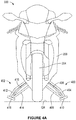
- Figure 4A illustrates a front view of the motorcycle 200 showing outriggers 400 and 402, in accordance with an example implementation.
- the motorcycle 200 is used herein as an example for illustration.
- the outriggers 400 and 402 described below could be used with any other type of vehicle that is laterally unstable when stopped.
- the left outrigger 400 has a first supporting member 404, a second supporting member 406, and a deployment or expansion member 408. Tips or distal ends of the first supporting member 404, the second supporting member 406, and the expansion member 408 are connected to each other by a pad 410.
- the right outrigger 402 has and a first supporting member 412, a second supporting member 414, and a deployment or expansion member 416. Tips or distal ends of the first support member 412, the second supporting member 414, and the expansion member 416 are connected to each other by a pad 418. Proximal ends of the supporting members 404-406 and the expansion member 408 are rotatably coupled to the motorcycle at respective pivots as shown and described below with respect to Figure 4B .
- the outriggers 402 (and also the outrigger 400 not shown in Figure 2 ) are in an undeployed, e.g., retracted state, and thus they are arranged along the sides of the vehicle body 206.
- the outrigger 402 could be arranged underneath the motorcycle 200 while in the undeployed state.
- the outrigger 402 could be arranged in other positions or configurations in the undeployed state such that it docs not impede leaning of the motorcycle 200.
- the pad 418 is located above the bottom of the vehicle body 206.
- the outriggers 400 and 402 are in a deployed state, and thus they are widened in the lateral direction of the motorcycle 200.
- the ground pads 410 and 418 are disposed below the bottom of the vehicle body 206. Particularly, in a state where the motorcycle 200 is upright in the vertical direction as shown in Figure 4A , the pads 410 and 418 do not contact the ground surface (GR), but are instead set at a particular height above the ground surface (GR). In this way, the outriggers 400 and 402 can be deployed even if the motorcycle 200 is tilted slightly to the left or right direction with respect to the vertical direction.
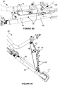
- the outrigger 400 may be biased by a biasing member 428 (e.g., a spring) coupled to the expansion member 408.
- the biasing member 428 may be configured to bias the outrigger 400 toward the deployed state.
- a limiting or holding member 430 may couple the outrigger actuator 426 to the outrigger 400 (e.g., to the first supporting member 404) and may be configured to hold the outrigger 400 in the undeployed state against the biasing force of the biasing member 428.
- the right outrigger 402 may be configured to operate similar to the left outrigger 400.
- the outrigger actuator 426 When the outrigger actuator 426 is triggered (e.g., a pneumatic cylinder is retracted), the wire loop 430 is released, and the biasing member 428 pushes the first and second expansion links 432 and 434 away from each other. Thus, the first and second expansion links 432 and 434 rotate relative to each other about the pivot 436 and the outrigger 400 switches to the deployed state shown in Figure 4E . As illustrated in Figure 4E , the deployment latch 440 closes, thus locking the second expansion link 434, and the first and second supporting members 404 and 406, in the expanded position. The outrigger 400 is thus deployed.
- the outrigger 402 may include similar components and operate similar to the outrigger 400.
- Figure 4F illustrates a perspective view of the robot 100 and the motorcycle 200 showing mounting the outrigger 402 to the motorcycle 200
- Figure 4G illustrates a zoomed-in view of the outrigger 402 as shown in Figure 4F , in accordance with an example implementation.
- the outrigger 402 and specifically, the first supporting member 412, may be mounted near a rear end of the motorcycle 200 by way of a swing arm 444 at a pivot 446.
- the second supporting member 414 may be rotatably coupled to the motorcycle 200 at a pivot 448.
- the outrigger 400 not shown in Figures 4F-4G may be similarly mounted to the motorcycle 200.
- the remote control device may have an emergency button that, when pressed or selected, an emergency signal is sent to the control unit 304 to deploy the outriggers 400-402.
- the control unit 304 may determine that such low speed indicates an emergency and deploys the outriggers 400-402 for safety reasons.
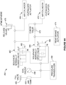
- Figure 4H illustrates a pneumatic circuit 450 showing operation of the outriggers 400-402 under various scenarios, in accordance with an example implementation.
- the circuit 450 represents a pneumatic system, a hydraulic system or other actuation mechanism could be used instead.
- Components of the circuit 450 may be coupled to the motorcycle 200 or the robot 100 or both.
- the circuit 450 includes a fill valve 452 that, when opened, allows compressed air to fill an air tank 454 that operates as a source of pressurized fluid (i.e., pressurized air or gas in this case).
- a dial gauge 456 may visually indicate pressure level of the pressurized gas in the tank 454, and a pressure transducer 458 may be configured to provide a signal to the control unit 304 indicating the pressure level.
- a first valve 460 is disposed in a first fluid path 462 between the tank 454 and air cylinders 464 and 470.
- the cylinder 464 may represent an outrigger actuator (e.g., the outrigger actuator 426) that when triggered, causes the corresponding outrigger (e.g., the outrigger 400) to deploy.
- the cylinder 470 may be the outrigger actuator corresponding to the other outrigger (e.g., the outrigger 402).
- a second valve 466 is disposed in a second fluid path 468 between the tank 454 and the cylinders 464 and 470.
- the first valve 460 may be a normally-closed valve that is electrically operated by a solenoid.
- the valve 460 blocks the first fluid path 462 from the tank 454 to the cylinders 464 and 470 until an electric signal is received from the control unit 304 to actuate the valve 460 and allow pressurized fluid to flow to the cylinders 464 and 470.
- the control unit 304 continuously provides a signal to the valve 466 so as to place the valve 466 in a closed state and block the second fluid path 468.
- the valve 466 switches to its normally-open state allowing pressurized fluid to flow through a check valve 472 to the cylinders 464 and 470, thus causing the outriggers to deploy.
- pressurized fluid also flows to a rear brake actuator 474 mounted to the robot 100 (also illustrated in Figure 4G ).
- the rear brake actuator 474 may be configured to override the second brake actuator 358 of the motorcycle 200 and apply the rear brakes when power is cut off from the valve 466.
- the rear brake actuator 474 may include a cylinder similar to the cylinders 464 and 470. When pressurized fluid flows to the cylinder of the actuator 474, the cylinder may retract, thus causing the right foot 110 to press the second brake operator 3 56.
- the circuit 450 may include a release valve 476 that is configured to release excess gas to the atmosphere to reduce pressure in the pneumatic system.
- the robot 100 has two arms 112 and 114 that may grip handles of the handlebar 308 of the motorcycle 200 so as to steer the motorcycle 200.
- each of the two arms 112 and 114 may be controlled by a corresponding actuator mechanism.
- the steering system uses an actuator mechanism configured to control both arms 112 and 114, as disclosed herein.
- the steering system disclosed herein further uses lightweight components and a fewer number of actuators to reduce weight and enable the robot 100 to mimic a human rider more accurately and provide more accurate feedback of dynamics of the motorcycle 200.
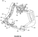
- FIG 5A illustrates a perspective view of a steering mechanism 500
- Figure 5B illustrates a top view of the steering mechanism 500, in accordance with an example implementation.
- the steering mechanism 500 includes the arms 112 and 114 of the robot 100 and left and right handlebars 502 and 504 composing the handlebar 308 of the motorcycle 200.
- the handlebars 502 and 504 are coupled to each other at, and are configured to rotate with respect to, a pivot 506.
- the second link 512, the arm 114, and the handlebar 504 form a four-bar mechanism.
- virtual bar 514 and virtual bar 516 are parallel and equal in length
- virtual bar 518 and virtual bar 520 are parallel and equal in length.
- a similar four-bar mechanism exists for the left side of the robot 100 and is not shown in Figure 5B to reduce visual clutter in the drawing.
- the two four-bar mechanisms arc symmetric with respect to each other, e.g., symmetric about a virtual line connecting a center of the rotary actuator 508 and a center of the pivot 506.
- the geometry of linkages of the four-bar mechanism i.e., geometry of the link 512, the arm 114, and the handlebar 504 is such that there is a 1:1 ratio between a rotary angle of the rotary actuator 508 and respective angles of the handlebars 502 and 504 with respect to the pivot 506.
- a 1:1 ratio exists between the rotary angle of the rotary actuator 508 and a steering angle of the motorcycle 200.
- This configuration permits the steering torque load on the handlebars 502 and 504 to be shared between both sets of linkages of the four-bar mechanisms while still allowing free movement of the handlebars 502 and 504. Further, the 1:1 ratio simplifies steering control as the steering angle is the same as the angle of the rotary actuator.
- An advantage of controlling steering with the two arms 112 and 114 over using one arm is that the load on the handlebars 502 and 504 is balanced.
- a one-armed steering system would experience a net force of torque over an arm, whereas the two-arm steering system may experience no additional net force while turning because the loads on the arms 112 and 114 cancel each other.
- the force that supports the steering rotary actuator 508 can be lower, and therefore a lighter supporting structure can be used.
- the steering mechanism 500 can accommodate horizontal displacements of the rotary actuator 508 or manufacturing misalignments/inaccuracies in positioning the rotary actuator 508 with respect to an axis 522 (shown in Figure 5A ) of the pivot 506. This accommodation results from spatial constraints placed on the rotary actuator 508 by the linkages of the above mentioned four-bar mechanisms. As such, manufacturing cost of the components of the steering system 500 may be reduced because high precision manufacturing cost is alleviated.
- standard planar pin joints may be located at vertices of the four-bar mechanisms (e.g., vertices of the four-bar mechanism illustrated by the virtual bars 514-520 in Figure 5B ).
- a passive rotational degree of freedom about an axis along the length of the arms 112 and 114 may be included. This could be achieved with a rotary bearing located at the end of the forearm before the wrist For instance, the rotary bearings could be placed at locations 524 and 526 shown in Figure 5A . This allows for some misalignment of the components without the actuator steering mechanism 500 binding under motion.
- each of the arms 112 and 114 may include a linear force sensor.
- the linear force sensors may be placed in various locations. For instance, the linear force sensors may be placed along a length of forearms 528 and 530 shown in Figure 5A .
- the overall force applied to the handlebars 502 and 504 may be determined by the difference between force measurements obtained by the two linear force sensors. For example, if the overall force is zero, then no torque is being applied to the handlebars 502 and 504 by the steering mechanism 500. In examples, to accurately compute torque from the linear force sensors, angles at the wrists may be taken into consideration and rotary position sensors may added at the locations 524 and 526 to determine these angles.
- a torque sensor 532 may be mounted to the rotary actuator 508 to provide redundant torque sensing.
- the torque sensor 532 corresponds to the torque sensor 324 mentioned above with respect to Figure 3A .
- angular position sensors may be mounted to the rotary actuator 508 and/or the pivot 506 to provide redundant rotary position sensing.
- the steering mechanism 500 may receive position and torque commands from the control unit 304.
- the control unit 304 may include a dynamic model of the motorcycle 200 and receive inputs from the sensors coupled to the robot 100 and the motorcycle 200. For instance, the control unit 304 may receive sensor information indicative of velocity, lean angle, heading of the motorcycle 200, and the status of the various actuators. Based on this information, the control unit 304 may determine outputs or commands to the actuators that operate the motorcycle 200 to control throttle, clutch, shifter, steering etc. and keep the motorcycle 200 moving at the desired velocity and trajectory.
- the steering mechanism 500 may receive a torque and rotary position or steering angle input command from the control unit 304, and the rotary actuator 508 accordingly rotates to achieve the commanded torque and steering angle.
- a linear actuator such as a hydraulic cylinder, a pneumatic cylinder, or an electric linear motor
- a first end of the linear actuator could be coupled to the first link 510 and a second of the linear actuator could be coupled to the second link 512.
- a linear position of the linear actuator e.g., linear position of a piston within a hydraulic cylinder determines the angles that the first handlebar 502 and the second handlebar 504 make relative to the pivot 506 and thus the steering angle.
- FIG. 5A and 5B includes a handlebar divided into two handlebars 502 and 504 coupled via the pivot 506, in other examples, a single undivided handlebar could be used.
- the left arm 112 would be coupled to a first end of the handlebar and the right arm 114 would be coupled to a second end of the handlebar.
- the first link 510, the left arm 112, and a portion of the handlebar form the first four-bar mechanism
- the second link 512, the right arm 114, and another portion of the handlebar form the second four-bar mechanism.
- the link members 330, 343, 350, and 359 could be twisted strings. These twisted strings change their length and apply a force when twisted by a corresponding actuator, i.e., the actuators 326, 342, 346, and 358, respectively.
- This section of the disclosure describes components and operation of an example twisted string actuator that includes a rotary actuator and a twisted string coupled thereto.
- FIG. 6A illustrates a twisted string actuator (TSA) 600
- FIG. 6B illustrates a close-up, cutaway view of elements of die TSA 600, in accordance with an example implementation.
- the TSA 600 includes an actuator head 602, a transmission tube 604, and a twisted string 606.
- the twisted string 606 could represent any of the link members 330, 343, 350, or 359, for example.
- a first end 608 of the twisted string 606 is rigidly connected to a plate 610 such that both torques and forces transmitted through the twisted string 606 are transmitted to the plate 610.
- the plate 610 could represent any of the operators 328, 338, 348, or 356 mentioned above.
- forces through and changes in length of the twisted string 606 induced by operation of a corresponding actuator 326, 342, 346, or 358 may result in application of force to and motion of the operators 328, 338, 348, or 356.
- a second end 612 (shown in Figure 6B ) of the twisted string 606, is attached to a rotor or other component of the actuator head 602. In this manner, forces transmitted through the twisted string 606 are transmitted between the plate 610 and the actuator head 602.
- the TSA 600 can be operated to produce a force and/or induce a displacement between the actuator head 602 and the plate 610 by applying a torque and/or rotation to the second end 612 of the twisted string 606. This force and/or displacement could cause a corresponding operator to move and/or to apply a force and/or torque. Additionally or alternatively, the TSA 600 could be actuated to reduce a force between the actuator head 602 and the plate 610 by reducing, removing, or otherwise changing a torque applied to the second end 612 of the twisted string 606.
- the transmission tube 604 is illustrated as a single, straight, rigid tube; however, in other examples, the transmission tube 604 could be curved, serpentine, or have some other shape. Additionally or alternatively, the transmission tube 604 could be flexible. In some examples, the transmission tube 604 could withstand longitudinal forces while allowing the transmission tube 604 to be bent, for example, around a joint that flexes during operation of the TSA 600. That is, the transmission tube 604 and the twisted string 606 partially contained therein could be configured analogously to the outer housing and inner cable, respectively, of a Bowden cable.
- the transmission tube 604 could be configured to be adjustable, such that properties of the TSA 600 are adjustable.
- the transmission tube 604 could include lockable and/or actuated telescoping elements such that the overall length of the transmission tube 604 (i.e., the length between the actuator head 602 and the end of the transmission tube 604 from which the twisted string 606 emerges) could be changed and/or controlled to control a range-of-motion, a transmission ratio, or some other property of the TSA 600.
- the TSA 600 includes a housing 614 that contains part of the transmission tube 604, part of the twisted string 606 (including first and second strands 606a and 606b), a load cell and encoder 616, a thrust bearing 618, a transmission block 620, a slip clutch 622, and a motor 624.
- the housing 614, the transmission tube 604, the load cell and encoder 616, stator elements of the thrust bearing 618, and stator elements of the motor 624 are rigidly mechanically coupled.
- the second end 612 of the twisted string 606, the transmission block 620, and a first end of the slip clutch 622 are rigidly mechanically connected.
- a second end of the slip clutch 622 and rotor elements of the motor 624 are rigidly connected.
- the motor 624 could be operated to generate a torque between the housing 614 and the second end of the slip clutch 622. This torque could be transmitted through the slip clutch 622 and the transmission block 620 to the twisted string 606, resulting in the TSA 600 applying a torque and/or force between the actuator head 602 and the plate 610. Further, this torque causes the twisted string 606 to change its length resulting in displacement between the actuator head 602 and the plate 610.
- the slip clutch 622 could be configured such that the torque transferred between the motor 624 and the transmission block 620 does not exceed a specified torque level.
- the specified torque level could be chosen or set such that a force applied between the actuator head 602 and the plate 610 by TSA 600 docs not exceed a specified force level.
- the specified force level could be related to the specified torque level and a transmission ratio of the TSA 600 related to the length of the twisted string 606 and the pitch of the twist of the strands 606a, 606b of the twisted string 606.
- the load cell and encoder 616 is configured to measure the force transmitted through, and the rotation of, the second end 612 of the twisted string 606.
- the load cell could include piezoelectric elements, strain gauges, or other elements configured to transduce the force transmitted from the second end 612 of the twisted string 606 into the transmission tube 604 and actuator head 602 into a signal or value indicating the transmitted force.
- the encoder could include optical or other elements capable of measuring the absolute and/or relative rotation of the second end 612 of the twisted string 606 directly and/or indirectly (e.g., by detecting absolute or relative rotation of the transmission block 620, twisted string 606. and/or a rotor of the thrust bearing 618).
- Information from the load cell and encoder 616 could be used to operate the TSA 600, for example, using closed-loop feedback control.
- the control unit 304 of the robot 100 could operate the motor 624 based on forces and/or rotations detected using the load cell and encoder 616 to generate a constant force in the twisted string 606, a constant rotation of the second end 612 of the twisted string 606, or a specific change in a length of the twisted string 606.
- control unit 304 could be configured to derive other detectable parameters of the TSA 600 and/or plate 610.
- the control unit 304 could be configured to determine a rotation rate of the second end 612 of the twisted string 606 corresponding to a specified rate of linear displacement between the actuator head 602 and the plate 610 based on a stored, known, or otherwise determined current length and/or level of twist of the twisted string 606.
- the control unit 304 could then operate the TSA 600 to achieve the specified rate of linear displacement by operating the motor 624 to achieve the rotation rate corresponding to the rate of linear displacement.
- Properties of the twisted string 606 and of the individual strands 606a, 606b of the twisted string 606 could be specified to satisfy some constraint(s) and/or to have some property(s) according to an application.
- a diameter and composition of the strands 606a, 606b could be chosen such that the twisted string 606 has a specified strength, fatigue resistance, transmission ratio, compliance, or some other property or properties.
- the strands 606a, 606b of the twisted string 606 could be wholly or partially composed of ultra-high-molecular-weight polyethylene or some other high strength, low bending radius, low internal friction, high stiffness material.
- the TSA 600 could include a string having two strands, like the strands 606a, 606b. or could include more than two strands.
- the arrangement of the two or more strands could be controlled and/or specified. In some examples, the arrangement of the two or more strands could be controlled by the configuration of the transmission block 620 or by the way in which ends of the strands opposite the transmission block 620 are attached to each other and/or to an actuated element.
- the TSA 600 shown in Figures 6A-6B is one implementation of a twisted string actuator as described herein.
- Other configurations of TSAs, including alternate, additional, fewer, and/or differently configured components are anticipated.
- a TSA could include multiple twisted strings, different number(s) of strands, multiple motors, twisted strings actuated by two rotational actuators (i.e., a rotational actuator coupled to each end of the twisted string), more than one transmission tube, differently configured transmission tubes, different locations and/or means of attachment to actuated elements, or other configurations according to an application.
- FIG. 7 illustrates a block diagram of a robot control system 700, in accordance with an example implementation.
- the robot control system 700 includes the control unit 304 and a remote control device 702.
- the control unit 304 includes the main controller 370 and the actuator control modules 372-384.
- the actuator control modules 372-384 are configured to control the various actuators of the robot 100 and the motorcycle 200.
- the accelerator module 372 is configured to control the accelerator actuator 318
- the first brake module 374 is configured to control the first brake actuator 326
- the second brake module 376 is configured to control the second (rear) brake actuator 358
- the steering module 378 is configured to control the steering actuator 322 (e.g., the rotary actuator 508)
- the clutch module 380 is configured to control the clutch actuator 346
- the shifter module 382 is configured to control the shift actuator 342
- the outrigger module 384 is configured to control the outrigger actuators (e.g., the outrigger actuator 426).
- the outrigger module 384 could be coupled to the motorcycle 200 or the robot 100.
- the actuator control modules 372-384 may be included within the control unit 304 along with the main controller 370. In other examples, the actuator control modules 372-384 may be separate from the controller 370 and may each have its own processor and memory programmed with instructions that, when executed by a respective processor, control a respective actuator.
- the actuator control modules 372-384 may be in wired or wireless communication with the main controller 370.
- the actuator control modules 372-384 may provide information to the main controller 370 and may receive commands from the main controller 370 to actuate the respective actuators.
- the main controller 370 includes at least one processor and a memory or data storage having program instructions stored thereon.
- the main controller 370 may be in wired or wireless communication with an onboard vehicle engine control unit (ECU) 704 and may be configured to receive control information of the motorcycle 200 from the vehicle ECU 704.
- the control information of the motorcycle 200 may include, for example, vehicle speed, engine speed, transmission gear position, etc.
- the vehicle speed can be a rotation speed of the front wheel 204 or the rear wheel 202.
- the main controller 370 may further receive an operation signal from the remote control device 702 (e.g., via the antenna 368). Based on the operation signal, the control information from the ECU 704, and roll angle information from the roll angle sensor 366, the main controller 370 may send command signals to the actuator control modules 372-384 to operate their respective actuators accordingly.
- the remote control device 702 may be located away from the robot 100.
- the remote control device 702 may include an operation unit 706 and a display 708.
- the operation unit 706 may include, for example, a joystick.
- the operator of the remote control device 702 can enter an accelerator command and steering command via the operation unit 706.
- the accelerator command could be acceleration or deceleration command and the steering command could be a left or right turn command.
- the operation unit 706 sends signals indicating these commands to the main controller 370. For example, when the joystick is tilted forward, the operation unit 706 sends an acceleration command to the main controller 370 based on the amount of tilt of the joystick. When the joystick is tilted rearward, the operation unit 706 transmits a deceleration command to the main controller 370 based on the amount of tilt. By tilting the joystick to the left, the operation unit 706 transmits a left turn steering command to the main controller 370 based on the amount of tilt to the left. By tilting the joystick to the right, the operation unit 706 transmits a right turn steering command to the main controller 370 based on the amount of tilt to the right.
- a joystick is used herein as an example, and the operation unit 706 may be a device or a user interface other than a joystick.
- the operation unit 706 may include a touch screen with user-interface items that the operator can use to provide acceleration and steering commands.
- the display 708 may be configured to receive and display images or video based on image data received from the imaging device 364. These images or video may inform the operator about the environment of the robot 100 and the motorcycle 200 to enable the operator to accelerate, decelerate, and steer the motorcycle 200 appropriately via the operation unit 706.
- the main controller 370 may be configured to analyze the image data received from the imaging device 346 and identify based on the image data any obstacles in a travel path of the robot 100 and the motorcycle 200. The main controller 370 may then determine the steering command and the accelerator command so as to avoid the obstacles and safely navigate the motorcycle 200.
- the main controller 370 may receive the accelerator and steering commands and accordingly provide signals to the actuator control modules 372-384.
- the main controller 370 may include a speed controller 710 that may include software modules, hardware components, or a combination thereof.
- the speed controller 710 may receive the accelerator command and accordingly send signals to the accelerator module 372, the first brake module 374, and the second brake module 376 to achieve the commanded acceleration/deceleration.
- the speed controller 710 may determine a target operational position for the accelerator 314 based on the accelerator command. The speed controller 710 may then send a command signal indicating the target operation position to the accelerator module 372. The accelerator module 372 then generates a signal to the accelerator actuator 318 so as to cause the actual operating position of the accelerator 314 detected by the position sensor 320 of the accelerator actuator 318 to approach the target operational position.
- the accelerator module 372 outputs a first driving signal to the accelerator actuator 318 to operate the accelerator 314 to open or further open a throttle of the engine 208.
- the accelerator module 372 outputs a signal to the accelerator actuator 318 to operate the accelerator 314 to reduce opening of the throttle of the engine 208.
- the speed controller 710 may determine a first target torque for the first brake actuator 326 and a second target torque of the second brake actuator 358. The speed controller 710 sends a command signal indicating the first target torque to the first brake module 374 and a command signal indicating the second target torque to the second brake module 376.
- the first brake module 374 sends a signal to the first brake actuator 326 so as to cause the torque of the first brake operator 328 detected by the torque sensor 332 to approach the first target torque.
- the second brake control module 376 sends a signal to the second brake actuator 358 so as to cause the torque of the second brake operator 356 detected by the torque sensor 360 to approach the second target torque. If there is no change in the accelerator command, the accelerator module 372 holds the accelerator 314 to its current operating position.
- the main controller 370 may further include a steering/balance controller 712 configured to perform steering and/or balance control in accordance with the steering command from the remote control device 702.
- the steering/balance controller 712 may include software modules, hardware components, or a combination thereof.
- the steering/balance controller 712 determines a target steering angle of the handlebar 308 (i.e., the left and right handlebars 502 and 504) based on the steering command from the remote control device 702. In response, the steering/balance controller 712 sends a command signal indicating the target steering angle to the steering module 378.
- the steering module 378 When the steering command indicates maintaining a straight path, the steering module 378 generates a signal to the steering actuator 322 (i.e., the rotary actuator 508) to cause the actual roll angle detected by the roll angle sensor 366 to be within a threshold value of zero roll angle to maintain a straight path.
- the steering module 378 may also generate the signal to the steering actuator 322 based on a torque detected by a torque sensor (e.g., the torque sensor 324 or 532) coupled to the steering actuator 322 and the actual steering angle of handlebar 308 detected by the steering position sensor 312.
- a torque sensor e.g., the torque sensor 324 or 532
- the steering module 378 When the steering command indicates a right turn or a left turn, the steering module 378 generates the steering signal to the steering actuator 322 based on one or more of several inputs: (i) the actual torque detected by the torque sensor 324 of the steering actuator 322, (ii) the actual steering angle of the handlebar 308 detected by the steering position sensor 312, (iii) the actual roll angle detected by the roll angle sensor 366, and (iv) the target steering angle.
- a turning radius is determined based on the steering command. Then, the steering controller 712 determines a target roll angle, a target steering angle, and a target steering torque based on the turning radius and the speed of the motorcycle 200. Based on determined target values, the steering controller 712 generates the steering command to the steering module 378, which provides a corresponding steering signal to the steering actuator 322. The steering controller 712 determines the steering command to reduce the difference between the target roll angle and the actual roll angle while monitoring the actual steering torque and the actual roll angle from the roll angle sensor 366 to achieve the commanded turn smoothly.
- the main controller 370 may further include a shift controller 714 configured to, based on the control information from the vehicle ECU 704, generate a gear-shift command. For instance, the shift controller 714, based on the vehicle speed received from the vehicle ECU 704, automatically performs a gear change operation by generating the shift command.
- the shift controller 714 may include software modules, hardware components, or a combination thereof.
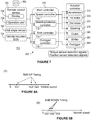
- Figure 8A is a diagram illustrating timing of shift-up, in accordance with an example implementation.
- the shift controller 714 when the speed of the motorcycle 200 reaches a first up-shift value, "Vul,” the shift controller 714 generates a signal to shift up the transmission from a first gear to a second gear allowing for higher speeds.
- the shift controller 714 When the speed increases to a second up-shift value, "Vu2,” the shift controller 714 generates a signal to shift up the transmission from the second gear to a third gear.
- the shift controller 714 When the speed further increases to a third up-shift value, "Vu3,” the shift controller 714 generates a signal to shift up the transmission from the third gear to a fourth gear.
- the shift controller 714 may prevent a shift-up in order to avoid destabilizing the motorcycle 200.
- Figure 8B is a diagram illustrating timing of shift-down, in accordance with an example implementation.
- the shift controller 714 when the speed of the motorcycle 200 decreases to a third down-shift value, "Vd3,” the shift controller 714 generates a signal to shift down the transmission from the fourth gear to the third gear.
- the shift controller 714 When the speed further decreases to a second down-shift value, "Vd2,” the shift controller 714 generates a signal to shift down the transmission from the third gear to the second gear.
- Vd1 When the speed decreases even further to a first down-shift value, "Vd1,” the shift controller 714 generates a signal to shift down the transmission from the second gear to the first gear.
- the main controller 370 may prevent downshifting to avoid destabilizing the motorcycle 200.
- gears were used herein as an example for illustration. However, a greater or fewer number of gears could be used.
- the shift controller 714 outputs command signals to the accelerator module 372, the shift module 382, and the clutch module 380 based on the shift command.
- the clutch module 380, the accelerator module 372, and the shift controller 68 generate respective signals to the respective actuators.
- Figures 9, 10, and 11 illustrate timing of accelerator, clutch, and shifter commands, in accordance with an example implementation.
- Figure 9 illustrates a timing chart at a beginning of executing a shift command, in accordance with an example implementation. Particularly, Figure 9 illustrates changes over time in the state of clutch operator 348 (top), the state of the accelerator 314 (middle), and the state of the shift operator 338 (bottom).
- the control unit 304 sends a command to change a position of the clutch operator 348 from the engagement position to the disengagement position at time (T1) to switch the clutch from the engaged state to the disengaged state and prepare for a gear-shift.
- T1 the clutch is switched from the engaged state to the disengaged state
- the control unit 304 changes the operating position of the shift operator 338 from the non-operation position to the first gear position at time (T2).
- T3 When the transmission is switched from the neutral position to the first gear position at time (T3), the control unit 304 returns the shift operator 338 to the non-operation position at time (T4).
- the control unit 304 When the shift operator 338 is returned to the non-operation position, the control unit 304 operates the accelerator 314 in the throttle opening direction at time (T4). When the accelerator 314 is operated in the throttle opening direction, rotational speed of the engine 208 increases. When the engine speed reaches a predetermined rotational speed, the control unit 304 holds the accelerator 314 to the operating position (TH1) at time (T5). Substantially simultaneously, the control unit 304 sends a signal to change position of the clutch operator 348 from the disengagement position toward the engagement position gradually between time (T5) and time (T6).
- control unit 304 may determine the rotational speed difference between the upstream side and the downstream side of the clutch.
- the rotational speed difference for example, is determined from the rotational speed of the engine 208 and the rotational speed of the rear wheel 202.
- the control unit 304 causes the clutch operator 348 to move to the engagement position.
- the clutch is engaged, the shift operation is completed at time (T7).
- Figure 10 is a timing chart illustrating shifting up, in accordance with an example implementation. Particularly, Figure 10 illustrates changes over time in the state of clutch operator 348 (top), the state of the accelerator 314 (middle), and the state of the shift operator 338 (bottom) during shifting up from a lower gear to a higher gear.
- the clutch operator 348 is in an engagement position and the clutch is engaged, the accelerator 314 is located at a predetermined operating position (TH2), and the shift operator 338 is located in the non-operation position. At this point, the transmission is in a first gear or a higher gear position.
- the control unit 304 sends signals to move the clutch operator 348 from the engagement position to the disengagement position and return the accelerator 314 to the fully closed position at time (T11).
- the control unit 304 sends a signal to switch the shift operator 338 from the non-operation position to the shift-up position at time (TI2).
- the transmission gear is switched to the higher-speed gear at time (T13), and the control unit 304 then returns the shift operator 338 to the non-operation position at time (T14).
- control unit 304 When the shift operator 338 is returned to the non-operation position, the control unit 304 substantially simultaneously actuates the accelerator 314 in the throttle opening direction back to the operating position (TH2) at time (T15). The control unit 304 then maintains the accelerator 314 at the operating position (TH2).
- the control unit 304 moves the clutch operator 348 to a half-clutch position from the disengagement position, and then the clutch operator 348 is held in the half-clutch position between time (T16) and time (T17).
- the control unit 304 may determine difference in the rotational speed between the upstream side and the downstream side of the clutch. When the difference is smaller than a predetermined threshold value at time (T17) , the control unit 304 moves the clutch operator 348 to the engagement position so as to place the clutch is the engaged state. The shift-up operation is completed at time (T18).
- Figure 11 is a timing chart illustrating shifting down, in accordance with an example implementation. Particularly, Figure 11 illustrates changes over time in the state of clutch operator 348 (top), the state of the accelerator 314 (middle), and the state of the shift operator 338 (bottom) during shifting down from a higher gear to a lower gear
- the clutch operator 348 before the shift-down at time (T0), the clutch operator 348 is in an engagement position, the accelerator 314 is located in the fully closed position and the shift operator 338 is in the non-operation position. At this point, the transmission is in second gear or a higher gear position.
- the control unit 304 sends a signal to move the clutch operator 348 from the engagement position to the disengagement position at time (T21).
- the control unit 304 sends a signal to move the accelerator 314 in the throttle opening direction to a predetermined position (TH3) and then return it to the fully closed position at time (T24) so as to make the speed of the engine 208 greater than a predetermined rotational speed.
- control unit 304 sends a signal to switch the shift operator 338 from the non-operation position to the shift-down position at time (T22) along with the above-mentioned movement of the accelerator 314.
- the transmission gear is thus switched to the low speed gear at time (T23) and the control unit 304 then returns the shift operator 338 to the non-operation position at time (T25).
- the control unit 304 sends a signal to move the clutch operator 348 from the disengagement position to the partial engagement position, and holds the clutch operator 348 in the half-clutch position between time (T27) and time (T28).
- control unit 304 determines a difference in the rotational speed between the upstream side and the downstream side of the clutch.
- the difference is smaller than a predetermined threshold value at time (T28)
- the control unit 304 moves the clutch operator 348 to the engagement position.
- the clutch is engaged and the shift-down operation is completed at time (T29).
- the control system 700 is described with reference to operating the robot 100 and the motorcycle 200 via the remote control device 702. However, in examples, the robot 100 may be configured to automatically control the motorcycle 200 without signals from a remote control device.
- Figure 12 illustrates a block diagram of an alternative robot control system 1200, in accordance with an example implementation.
- the robot 100 may include a memory or data storage 1202 (e.g., any type of memory, non-transitory computer-readable medium, transitory computer-readable medium, or both a non-transitory computer-readable medium and a transitory computer-readable medium).
- the data storage 1202 may be coupled to the robot 100 or the motorcycle 200.
- the data storage 1202 may store a sequence of accelerator commands and steering commands, and the control unit 304 may acquire these commands from the data storage 1202 to operate the robot 100 and the motorcycle 200.
- the data storage 1202 may store a travel route for the motorcycle 200.
- the control unit 304 may then determine the accelerator commands and steering commands to execute the travel route.
- the data storage 1202 may be built in the robot 100, and the control unit 304 may receive accelerator commands, steering commands, shift commands, and a travel route from the data storage 1202 via wired or wireless communication.
- the data storage 1202 may include a recording medium removable from the robot 100. The removable medium could be connected to other computing devices to acquire operating instruction/commands and the travel route. The data storage 1202 may then be reconnected to the robot 100 or the motorcycle to transmit the operating instruction/commands and the travel route to the control unit 304.
- the data storage 1202 may store thereon a target position and a target speed for the motorcycle 200.
- the robot 100 or the motorcycle 200 may include a global position system (GPS) device.
- GPS global position system
- the GPS device may include any sensor configured to estimate a geographic location of the robot 100 or the motorcycle 200.
- the GPS device may include a transceiver configured to estimate a position of the robot 100 or the motorcycle 200 with respect to the Earth based on satellite-based positioning data.
- the GPS device may be in communication with the main controller 370 or the control unit 304 and may be configured to provide information indicative of the location of robot 100 or the motorcycle 200 thereto.
- the control unit 304 may then determine the steering command and the accelerator command based at least in part on the target position, the target speed, and the location information received from the GPS device so as to navigate to the target position.
- the motorcycle 200 is used as an example for illustration, but any other type of vehicle could be used.
- a vehicle could be a mobile machine that can be used to transport a person, people, or cargo.
- any vehicle discussed herein can be driven and/or otherwise guided along a path (e.g., a paved road or otherwise) on land, in water, on water, or in the air or outer space.
- a path e.g., a paved road or otherwise
- any vehicle discussed herein can be wheeled, tracked, railed, or skied.
- any vehicle discussed herein can include an automobile, a motorcycle, an all-terrain vehicle (ATV) defined by ANSI/SV1A-1-2007, a snowmobile, a personal watercraft, a light-duty truck, a medium-duty truck, a heavy-duty truck, a semi-tractor, a farm machine, or a construction machine.
- ATV all-terrain vehicle
- a vehicle guided along a path can include a van (such as a dry or refrigerated van), a tank trailer, a platform trailer, or an automobile carrier.
- accelerator operation member is not limited to the accelerator grip described above, but may include other forms such as an accelerator pedal or an accelerator lever.
- the steering operator is not limited to a handlebar, but may include a steering lever, steering wheel, or any other form.
- the brake operator and clutch operator may be modified to operate similar to the shift operator. In examples, the brake operator, clutch operator, or shift operator may be omitted.
- the structure of the robot 100 is not limited to the structure of the above implementations.
- the structure of the left and right feet, the left and right legs, the left and right arms, or the left and right hands may be changed.
- the structure of the outriggers may also be changed.
- the outriggers may be omitted.
- control unit 304 may also be changed.
- the main controller 370 and the actuator control modules 372-384 are provided separately. In other implementations, all or some of them may be integrated in a single controller.
- the configuration of the motorcycle 200 may also be changed.
- the engine 208, the fuel tank 210, and the position of the driver's seat 212 may be changed. Additionally, more than one front wheel could be used and more than one rear wheel could be used.
Landscapes
- Engineering & Computer Science (AREA)
- Robotics (AREA)
- Mechanical Engineering (AREA)
- Multimedia (AREA)
- Physics & Mathematics (AREA)
- General Physics & Mathematics (AREA)
- Radar, Positioning & Navigation (AREA)
- Remote Sensing (AREA)
- Human Computer Interaction (AREA)
- Theoretical Computer Science (AREA)
- Aviation & Aerospace Engineering (AREA)
- Automation & Control Theory (AREA)
- Manipulator (AREA)
- Business, Economics & Management (AREA)
- Health & Medical Sciences (AREA)
- Artificial Intelligence (AREA)
- Evolutionary Computation (AREA)
- Game Theory and Decision Science (AREA)
- Medical Informatics (AREA)
- Regulating Braking Force (AREA)
- Mechanical Control Devices (AREA)
- Control Of Driving Devices And Active Controlling Of Vehicle (AREA)
Claims (13)
- Système comprenant :un véhicule (200) comprenant un opérateur d'accélérateur (314) à l'aide duquel la vitesse du véhicule peut être augmentée/diminuée et un opérateur de guidage (388) ;un robot humanoïde (100) comprenant : (i) un actionneur d'accélérateur (318) couplé à l'opérateur d'accélérateur (314) du véhicule (200) et configuré pour actionner l'opérateur d'accélérateur (314), et (ii) un actionneur de guidage (322) couplé à l'opérateur de guidage (388) du véhicule et configuré pour actionner l'opérateur de guidage (388) ; etun dispositif de commande (370) configuré pour :en réponse à une instruction d'accélérateur, envoyer un premier signal à l'actionneur d'accélérateur (318) pour actionner l'opérateur d'accélérateur (314) du véhicule (200), eten réponse à une instruction de guidage, envoyer un deuxième signal à l'actionneur de guidage (322) pour guider le véhicule (200),caractérisé en ce quele robot humanoïde (100) comprend en outreun actionneur de frein (326) configuré pour actionner un opérateur de frein (328) du véhicule (200), dans lequel le dispositif de commande (370) est en outre configuré pour,en réponse à une instruction de freinage, envoyer un troisième signal à l'actionneur de frein (326) pour actionner l'opérateur de freinage (328).
- Système selon la revendication 1, dans lequel l'instruction d'accélérateur comprend une instruction de décélération, et dans lequel le premier signal à l'actionneur d'accélérateur (318) amène l'actionneur à revenir vers une position non actionnée pour décélérer le véhicule (200), ou
le véhicule (200) comprend en outre : un opérateur de changement de vitesse (338) et un opérateur d'embrayage (348), le robot (100) comprenant en outre : un actionneur de changement de vitesse (342) configuré pour actionner l'opérateur de changement de vitesse (338) et un actionneur d'embrayage (346) configuré pour actionner l'opérateur d'embrayage (348), et dans lequel le dispositif de commande (370) est en outre configuré pour, en réponse à un ordre de changement de rapport de vitesse, envoyer le premier signal à l'actionneur d'accélérateur (318), un troisième signal à l'actionneur d'embrayage (346), et un quatrième signal à l'actionneur de changement de vitesse (342) de manière à séquentiellement actionner l'opérateur d'accélérateur (314), désengager un embrayage, et actionner l'opérateur de changement de vitesse (338) pour provoquer un changement de rapport de vitesse, ou
le robot (100) comprend en outre un corps principal (102) qui est placé sur un siège conducteur du véhicule (200), et dans lequel au moins l'un parmi l'actionneur d'accélérateur (318) ou l'actionneur de guidage (322) est connecté au corps principal (102), de préférence le corps principal (102) comprend un élément d'assise (362) couplé au siège conducteur. - Système selon la revendication 1, dans lequel le dispositif de commande (370) est un premier dispositif de commande (370) couplé au robot (100), dans lequel le véhicule (200) comprend un second dispositif de commande (710) en communication avec le premier dispositif de commande (370), dans lequel le second dispositif de commande (710) est configuré pour fournir des informations indicatives d'une vitesse du véhicule (200) au premier dispositif de commande (370), et dans lequel le premier dispositif de commande (370) détermine le premier signal et le deuxième signal sur la base des informations indicatives de la vitesse du véhicule (200), ou
le robot (100) comprend en outre :une mémoire (1202) en communication avec le dispositif de commande (370) et configurée pour y stocker l'instruction d'accélérateur et l'instruction de guidage, le dispositif de commande (370) étant configuré pour recevoir l'instruction d'accélérateur et l'instruction de guidage en provenance de la mémoire (1202), oule robot (100) comprend en outre :une mémoire (1202) en communication avec le dispositif de commande (370) et configurée pour y stocker un itinéraire de déplacement pour le véhicule (200), dans lequel le dispositif de commande (370) est configuré pour déterminer le premier signal et le deuxième signal sur la base de l'itinéraire de déplacement, oule robot (100) comprend en outre :une mémoire (1202) en communication avec le dispositif de commande (370) et configurée pour y stocker une position cible et une vitesse cible pour le véhicule (200) ; etun dispositif de système de positionnement global (GPS) en communication avec le dispositif de commande (370) et configuré pour fournir au dispositif de commande (370) des informations indicatives d'une position actuelle du robot (100), dans lequel le dispositif de commande (370) détermine le premier signal et le deuxième signal sur la base de la position cible, de la vitesse cible, et des informations indicatives de la position actuelle du robot (100), oucomprenant en outre :
un dispositif de commande à distance (702), dans lequel le dispositif de commande (370) reçoit l'instruction d'accélérateur et l'instruction de guidage en provenance du dispositif de commande à distance (702), comprenant de préférence en outre :
un dispositif d'imagerie (364) couplé au robot (100) ou au véhicule (200) et en communication avec le dispositif de commande (370), dans lequel le dispositif de commande (370) est configuré pour transmettre des données d'image capturées par le dispositif d'imagerie (364) pour un environnement du robot (100) et du véhicule (200) au dispositif de commande à distance (702), dans lequel le dispositif de commande à distance (702) comprend un affichage (708) configuré pour afficher une ou plusieurs images sur la base des données d'image reçues du dispositif de commande (370). - Système selon la revendication 1, dans lequel le robot (100) comprend en outre un dispositif d'imagerie (364) configuré pour fournir au dispositif de commande (370) des données d'image pour un environnement du robot (100), dans lequel le dispositif de commande (370) est configuré pour :identifier, sur la base des données d'image, un obstacle dans un trajet du véhicule (200), etdéterminer le deuxième signal de manière à éviter l'obstacle, oule véhicule (200) comprend en outre : un opérateur de frein (328), dans lequel le robot (100) comprend en outre un actionneur de frein (326) configuré pour actionner l'opérateur de frein (328), et dans lequel le dispositif de commande (370) est en outre configuré pour envoyer le premier signal à l'actionneur d'accélérateur (318) et un troisième signal à l'actionneur de frein (326) de manière à obtenir une accélération ou décélération particulière pour le véhicule (200).
- Système selon l'une quelconque des revendications 1 à 4, dans lequel le robot (100) comprend en outre :un bras (112) configuré pour guider le véhicule (200) ;un actionneur (508) couplé au bras (112) via une liaison (510) ; etle dispositif de commande (370) est configuré pour :
en réponse à l'instruction de guidage, envoyer le deuxième signal à l'actionneur (508), en amenant ainsi l'actionneur (508) à appliquer un couple particulier à la liaison (510) de manière à guider le véhicule (200). - Système selon l'une quelconque des revendications 1 à 5, dans lequel le véhicule (200) comprend :
un guidon (308), dans lequel le bras (122) du robot (100) est configuré pour se coupler à une extrémité du guidon (308), de préférence la liaison (510), le bras (112), et une partie du guidon (308) forment un mécanisme de type quatre barres. - Système selon la revendication 6, dans lequel le bras est un premier bras (112) et la liaison est une première liaison (510), et le mécanisme de type quatre barres est un premier mécanisme de type quatre barres,
le robot (100) comprend un second bras (114),
l'actionneur (508) est couplé au premier bras (112) via la première liaison (510) et est couplé au second bras (114) via une seconde liaison (512), et
la seconde liaison (512), le second bras (114), et une autre partie du guidon (308) forment un second mécanisme de type quatre barres symétrique par rapport au premier mécanisme de type quatre barres, de sorte qu'une position particulière de l'actionneur (508) détermine un angle du guidon (308), de préférence le premier mécanisme de type quatre barres et le second mécanisme de type quatre barres sont disposés de telle sorte qu'il existe un rapport 1:1 entre la position particulière de l'actionneur (508) et l'angle du guidon (308). - Système selon l'une quelconque des revendications 1 à 7, le robot (100) comprenant en outre :de préférence l'actionneur de frein (326) avec un actionneur à cordon torsadé (600) qui comprend un moteur électrique couplé à un élément de cordon comprenant une pluralité de brins flexibles, dans lequel le troisième signal actionne le moteur électrique pour amener le cordon à se tordre et une longueur du cordon à diminuer, oucomprenant en outre :un capteur d'angle de roulis (366), dans lequel le dispositif de commande (370) est configuré pour envoyer le deuxième signal à l'actionneur sur la base d'une différence entre un angle de roulis cible déterminé par l'instruction de guidage et un angle de roulis actuel détecté par le capteur d'angle de roulis (366), ouun actionneur de changement de vitesse (342) configuré pour actionner un opérateur de changement de rapport de vitesse (338) du véhicule (200), dans lequel le dispositif de commande (370) est en outre configuré pour :en réponse à une instruction de changement de vitesse, envoyer un troisième signal à l'actionneur de changement de vitesse (342) pour actionner l'opérateur de rapport de changement de vitesse (338), ouun actionneur d'embrayage (346) configuré pour actionner un opérateur d'embrayage (348) du véhicule (200), dans lequel le dispositif de commande (370) est en outre configuré pour :
en réponse à une instruction d'embrayage, envoyer un troisième signal à l'actionneur d'embrayage (346) pour actionner l'opérateur d'embrayage (348), de préférence l'actionneur d'embrayage (346) comprend un actionneur à cordon torsadé (600) qui comprend un moteur électrique couplé à un élément de cordon comprenant une pluralité de brins flexibles, dans lequel le troisième signal actionne le moteur électrique pour amener le cordon à se tordre et une longueur du cordon à diminuer. - Système selon l'une quelconque des revendications 1 à 8, comprenant en outre :au moins un stabilisateur (400) couplé au véhicule (200) ou au robot (100) et configuré pour être dans un état non déployé ou dans un état déployé, dans lequel dans l'état déployé, le stabilisateur (400) est configuré pour mettre en prise une surface lorsque le véhicule (200) est à un angle d'inclinaison prédéterminé pour stabiliser latéralement le véhicule (200) ;un actionneur de stabilisateur (426) configuré pour commuter le stabilisateur (400) de l'état non déployé en l'état déployé ; etun dispositif de commande (370) configuré pour :en réponse à une instruction d'accélérateur, envoyer un premier signal à l'actionneur d'accélérateur (318) pour actionner l'opérateur d'accélérateur (314) du véhicule (200), en réponse à une instruction de guidage, envoyer un deuxième signal à l'actionneur de guidage (322) pour guider le véhicule (200), eten réponse à un signal de déploiement de stabilisateur, envoyer un troisième signal pour actionner l'actionneur de stabilisateur (426) de manière à commuter le stabilisateur (400) de l'état non déployé en l'état déployé pour stabiliser latéralement le véhicule (200).
- Système selon la revendication 9, dans lequel le stabilisateur (400) comprend un ou plusieurs éléments de support (404 406) et un élément d'expansion (408), dans lequel :
des extrémités proximales des un ou plusieurs éléments de support (404, 406) et de l'élément d'expansion (408) sont couplées en rotation au véhicule (200) au niveau de pivots respectifs (436), et des extrémités distales des un ou plusieurs éléments de support (404, 406) et de l'élément d'expansion (408) sont couplées à un patin configuré pour mettre en prise la surface lorsque le stabilisateur (400) est dans l'état déployé. - Système selon la revendication 10, dans lequel le stabilisateur (400) comprend en outre :
un élément de sollicitation (428) couplé à l'élément d'expansion (408) et configuré pour appliquer une force de sollicitation sur le stabilisateur (400) pour solliciter le stabilisateur (400) vers l'état déployé ; un élément de maintien (430) qui couple l'actionneur de stabilisateur (426) à l'un des un ou plusieurs éléments de support (404, 406), dans lequel l'élément de maintien (430) est configuré pour maintenir le stabilisateur (400) dans l'état non déployé à l'encontre de la force de sollicitation de l'élément de sollicitation (428), dans lequel lorsque l'actionneur de stabilisateur (426) est déclenché alors que le stabilisateur (400) est dans l'état non déployé, l'élément de maintien (430) est libéré et l'élément de sollicitation (428) amène le stabilisateur (400) à commuter de l'état non déployé en l'état déployé. - Système selon la revendication 11, dans lequel l'élément de sollicitation (428) comprend au moins l'un parmi un ressort linéaire de compression ou un ressort de torsion, ou
l'élément de maintien (430) comprend une boucle de fil qui relie l'actionneur de stabilisateur (426) à l'un des un ou plusieurs éléments de support, ou
l'élément d'expansion (408) comprend une première liaison d'expansion (432) et une seconde liaison d'expansion (434) couplée à la première liaison d'expansion (432) via un pivot (436), dans lequel l'élément de sollicitation (428) est monté à travers le pivot (436) et est configuré pour appliquer la force de sollicitation pour solliciter la seconde liaison d'expansion (434) au loin de la première liaison d'expansion (432), et dans lequel lorsque l'élément de maintien (430) est libéré, l'élément de sollicitation (428) pousse la seconde liaison d'expansion (434) au loin de la première liaison d'expansion (432), en amenant ainsi le stabilisateur (400) à commuter de l'état non déployé en l'état déployé. - Système selon la revendication 9, dans lequel l'actionneur de stabilisateur (426) comprend un vérin hydraulique ou pneumatique, dans lequel le véhicule (200) comprend en outre : (i) une source (454) de fluide sous pression ; (ii) une première vanne (460) disposée entre la source (454) de fluide sous pression et le vérin, dans lequel la première vanne (460) bloque un premier trajet de fluide (462) entre la source (454) et le vérin ; et (iii) une seconds vanne (466) disposée entre la source (454) de fluide sous pression et le vérin, dans lequel la seconde vanne (466) bloque un deuxième trajet de fluide entre la source (454) de fluide sous pression et le vérin, de préférence
en réponse au signal de déploiement du stabilisateur (400) pendant un fonctionnement normal, le dispositif de commande (370) ouvre la première vanne (460) pour ouvrir le premier trajet de fluide (462) entre la source (454) de fluide sous pression et le vérin de manière à actionner l'actionneur de stabilisateur (426) et déployer le stabilisateur (400), et
en réponse au signal de déploiement de stabilisateur indiquant un signal d'urgence ou qu'une vitesse du véhicule (200) est inférieure à une vitesse de seuil, le dispositif de commande (370) ouvre la seconde vanne (466) pour ouvrir le deuxième trajet de fluide entre la source (454) de fluide sous pression et le vérin pour actionner l'actionneur de stabilisateur (426) et déployer le stabilisateur (400), comprenant de préférence en outre :
un actionneur de frein arrière (326), dans lequel en réponse au signal d'urgence ou à la vitesse du véhicule (200) qui est inférieure à la vitesse de seuil, le dispositif de commande (370) ouvre la seconde vanne (466) pour ouvrir un troisième trajet de fluide entre le la source (454) de fluide sous pression et l'actionneur de frein arrière (326) pour actionner un frein arrière du véhicule (200) tout en déployant le stabilisateur (400).
Applications Claiming Priority (3)
| Application Number | Priority Date | Filing Date | Title |
|---|---|---|---|
| US201562245564P | 2015-10-23 | 2015-10-23 | |
| US201562248445P | 2015-10-30 | 2015-10-30 | |
| PCT/US2016/058039 WO2017070426A1 (fr) | 2015-10-23 | 2016-10-21 | Robot et système de commande de robot |
Publications (3)
| Publication Number | Publication Date |
|---|---|
| EP3365143A1 EP3365143A1 (fr) | 2018-08-29 |
| EP3365143A4 EP3365143A4 (fr) | 2018-11-21 |
| EP3365143B1 true EP3365143B1 (fr) | 2020-08-12 |
Family
ID=58557836
Family Applications (1)
| Application Number | Title | Priority Date | Filing Date |
|---|---|---|---|
| EP16858265.8A Active EP3365143B1 (fr) | 2015-10-23 | 2016-10-21 | Robot et système de commande de robot |
Country Status (5)
| Country | Link |
|---|---|
| US (1) | US10899016B2 (fr) |
| EP (1) | EP3365143B1 (fr) |
| JP (1) | JP6649477B2 (fr) |
| AU (2) | AU2016342272A1 (fr) |
| WO (1) | WO2017070426A1 (fr) |
Families Citing this family (14)
| Publication number | Priority date | Publication date | Assignee | Title |
|---|---|---|---|---|
| WO2016187211A1 (fr) * | 2015-05-19 | 2016-11-24 | The Regents Of The University Of California | Actionneur linéaire à structure d'adn |
| DE102018200435B3 (de) * | 2017-07-31 | 2018-11-15 | Volkswagen Aktiengesellschaft | Kraftfahrzeug und Verfahren zum Steuern eines Roboters |
| JP6712583B2 (ja) | 2017-10-20 | 2020-06-24 | ヤマハ発動機株式会社 | 駐車装置および発進補助装置 |
| US10864959B2 (en) * | 2017-10-23 | 2020-12-15 | Honda Motor Co., Ltd. | Vehicle and related control system |
| US10647329B2 (en) * | 2017-12-12 | 2020-05-12 | Uatc, Llc | Disengaging autonomous control of vehicle |
| EP3508760A1 (fr) * | 2018-01-05 | 2019-07-10 | Yamaha Hatsudoki Kabushiki Kaisha | Véhicule |
| US20190210591A1 (en) * | 2018-01-08 | 2019-07-11 | Sri International | System and Method to Enhance the Driving Performance of a Leanable Vehicle |
| US11318607B2 (en) | 2019-01-04 | 2022-05-03 | Universal City Studios Llc | Extended reality ride test assembly for amusement park system |
| EP3909830A1 (fr) * | 2020-04-20 | 2021-11-17 | KA Group AG | Système de commande de conduite amélioré pour motoneiges |
| CN111924018A (zh) * | 2020-06-04 | 2020-11-13 | 酷至家(广州)智能科技发展有限公司 | 一种机器人司机 |
| TWI805978B (zh) * | 2020-12-22 | 2023-06-21 | 達明機器人股份有限公司 | 雙迴路力矩感知系統及其感知方法 |
| US12084204B2 (en) * | 2021-06-29 | 2024-09-10 | Air T, Inc. | Remote deicing/anti-icing |
| WO2024224532A1 (fr) * | 2023-04-26 | 2024-10-31 | 株式会社ソニー・インタラクティブエンタテインメント | Dispositif de fixation, système de traitement d'informations, procédé de fonctionnement et programme de fonctionnement |
| DE102023111659A1 (de) | 2023-05-04 | 2024-11-07 | Daimler Truck AG | Schnittstellenanordnung im Fahrzeug für einen humanoiden Roboter |
Family Cites Families (38)
| Publication number | Priority date | Publication date | Assignee | Title |
|---|---|---|---|---|
| US3465577A (en) * | 1967-09-28 | 1969-09-09 | Rca Corp | Automobile control manipulating apparatus |
| US3546814A (en) * | 1969-02-24 | 1970-12-15 | Federico Melendez | Robot driver of a two-wheel motorcycle |
| US3826038A (en) * | 1972-12-13 | 1974-07-30 | A Gentilini | Bicycle toy which can be either manually operated or remote controlled by means of a wire control or by radio control |
| US4046262A (en) * | 1974-01-24 | 1977-09-06 | The United States Of America As Represented By The Administrator Of The National Aeronautics And Space Administration | Anthropomorphic master/slave manipulator system |
| ATE42831T1 (de) * | 1986-03-04 | 1989-05-15 | Schenck Ag Carl | Bezugsplattform fuer eine arretierbare aufstellung. |
| US4799915A (en) * | 1987-12-04 | 1989-01-24 | Lehmann Roger W | Radio-controlled robot operator for battery-powered toys |
| DE3940588A1 (de) * | 1989-12-08 | 1991-06-13 | Georg Witt | Fahrroboter |
| US5029894A (en) * | 1990-03-30 | 1991-07-09 | Willman David M | Retractable motorcycle stop-support wheels |
| JPH0743296B2 (ja) * | 1991-01-16 | 1995-05-15 | 株式会社堀場製作所 | 自動車自動運転ロボットの制御方法 |
| JPH05312686A (ja) * | 1992-05-09 | 1993-11-22 | Horiba Ltd | 自動車自動運転ロボットの制御方法 |
| US5368516A (en) * | 1993-10-21 | 1994-11-29 | Bang Zoom Design Inc. | Radio controlled two-wheeled toy motorcycle |
| US5865266A (en) * | 1996-05-02 | 1999-02-02 | Chrysler Corporation | Steering wheel linkage for robotic system for automated durability road (ADR) facility |
| GB2322354B (en) * | 1997-02-25 | 2000-05-10 | Fki Engineering Plc | Robot for operating motor vehicle control |
| JP4229568B2 (ja) * | 2000-03-30 | 2009-02-25 | 株式会社小野測器 | 2輪車用走行試験装置 |
| US6637763B2 (en) * | 2001-12-05 | 2003-10-28 | Ming C. Kuo | Enclosed motorcycle |
| EP1526998B1 (fr) * | 2002-08-09 | 2008-09-17 | Peraves Aktiengesellschaft | Systeme pour stabiliser un vehicule a voie unique et vehicule a voie unique equipe d'un tel systeme |
| JP4381940B2 (ja) * | 2004-09-15 | 2009-12-09 | 株式会社小野測器 | 車両用走行試験装置 |
| US8078338B2 (en) * | 2004-10-22 | 2011-12-13 | Irobot Corporation | System and method for behavior based control of an autonomous vehicle |
| DE102006061483B4 (de) * | 2006-02-22 | 2024-01-25 | Continental Automotive Technologies GmbH | Verfahren und Vorrichtung zur Bestimmung des Rollwinkels eines Kraftrades |
| EP1998989B1 (fr) * | 2006-03-21 | 2015-07-01 | Koninklijke Philips N.V. | Appareil et procede pour determiner l'angle de roulis de motocycle |
| US8051936B1 (en) * | 2006-08-30 | 2011-11-08 | The United States Of America As Represented By The Secretary Of The Navy | Human-portable remote control driving system |
| US7628239B1 (en) * | 2006-08-30 | 2009-12-08 | The United States Of America As Represented By The Secretary Of The Navy | Adaptable remote control driving system |
| JP2008079371A (ja) | 2006-09-19 | 2008-04-03 | Nippon Densan Corp | ねじれ紐式アクチュエータ |
| JP2008175564A (ja) * | 2007-01-16 | 2008-07-31 | Yamaha Motor Co Ltd | 自動二輪車の走行試験システム |
| US8260535B2 (en) * | 2007-09-28 | 2012-09-04 | Bombardier Recreational Products Inc. | Load sensor for a vehicle electronic stability system |
| US8255093B2 (en) * | 2008-08-29 | 2012-08-28 | Raytheon Company | Kit to adapt an automotive vehicle for remote operation, automotive remote control conversion pedestal, and system |
| JP5134527B2 (ja) * | 2008-12-25 | 2013-01-30 | 川崎重工業株式会社 | 自動二輪車のバンク角検知装置およびヘッドランプ装置 |
| DE102010003951A1 (de) * | 2010-04-14 | 2011-10-20 | Robert Bosch Gmbh | Verfahren zum Stabilisieren eines Zweirads bei seitlich rutschendem Hinterrad |
| JP5713741B2 (ja) * | 2011-03-18 | 2015-05-07 | 本田技研工業株式会社 | 自動二輪車の変速制御装置 |
| JP5926095B2 (ja) * | 2012-03-30 | 2016-05-25 | 本田技研工業株式会社 | 自動二輪車用トラクション制御装置 |
| US8746721B2 (en) * | 2012-07-26 | 2014-06-10 | Jean-Michel Thiers | Motorcycle steering with four-bar linkage |
| US8480111B1 (en) * | 2012-11-02 | 2013-07-09 | Ming C. Kuo | Enclosed motorcycle |
| JP5890771B2 (ja) * | 2012-12-27 | 2016-03-22 | 本田技研工業株式会社 | 移動体 |
| KR101779100B1 (ko) * | 2013-03-15 | 2017-09-18 | 에스알아이 인터내셔널 | 엑소수트 시스템 |
| KR101446111B1 (ko) * | 2013-09-25 | 2014-11-03 | 한국기술교육대학교 산학협력단 | 운전 제어 장치 |
| US9364178B2 (en) * | 2013-11-26 | 2016-06-14 | Elwha Llc | Robotic vehicle control |
| US9844880B1 (en) * | 2014-08-07 | 2017-12-19 | Kairos Autonomi, Inc. | Unmanned vehicle retrofitting applique assembly |
| WO2016178213A1 (fr) * | 2015-05-05 | 2016-11-10 | B.G. Negev Technologies And Applications Ltd. | Système de conduite robotique autonome universel |
-
2016
- 2016-10-21 WO PCT/US2016/058039 patent/WO2017070426A1/fr not_active Ceased
- 2016-10-21 JP JP2018519303A patent/JP6649477B2/ja active Active
- 2016-10-21 EP EP16858265.8A patent/EP3365143B1/fr active Active
- 2016-10-21 US US15/768,311 patent/US10899016B2/en active Active
- 2016-10-21 AU AU2016342272A patent/AU2016342272A1/en not_active Abandoned
-
2020
- 2020-03-06 AU AU2020201692A patent/AU2020201692B2/en active Active
Non-Patent Citations (1)
| Title |
|---|
| GUIZZO ERICO ET AL: "The hard lessons of DARPA's robotics challenge [News]", IEEE SPECTRUM, IEEE INC. NEW YORK, US, vol. 52, no. 8, 1 August 2015 (2015-08-01), pages 11 - 13, XP011664195, ISSN: 0018-9235, [retrieved on 20150722], DOI: 10.1109/MSPEC.2015.7164385 * |
Also Published As
| Publication number | Publication date |
|---|---|
| EP3365143A1 (fr) | 2018-08-29 |
| AU2020201692A1 (en) | 2020-03-26 |
| EP3365143A4 (fr) | 2018-11-21 |
| JP2019502583A (ja) | 2019-01-31 |
| WO2017070426A1 (fr) | 2017-04-27 |
| AU2016342272A1 (en) | 2018-05-10 |
| US20180297209A1 (en) | 2018-10-18 |
| US10899016B2 (en) | 2021-01-26 |
| AU2020201692B2 (en) | 2021-07-15 |
| JP6649477B2 (ja) | 2020-02-19 |
Similar Documents
| Publication | Publication Date | Title |
|---|---|---|
| EP3365143B1 (fr) | Robot et système de commande de robot | |
| US11904648B2 (en) | Adjustable suspensions and vehicle operation for off-road recreational vehicles | |
| US10144452B2 (en) | Active adaptive haptic multi-function knob | |
| US20130131923A1 (en) | Vehicle and method of controlling thereof | |
| EP2905157B1 (fr) | Appareil d'ajustement de suspension | |
| RU2627219C2 (ru) | Система помощи при движении транспортного средства задним ходом с прицепом | |
| US10196088B2 (en) | Target monitoring system and method | |
| US8301354B2 (en) | Vehicle | |
| US9533683B2 (en) | Sensor failure mitigation system and mode management | |
| US11358572B2 (en) | Brake control system and method for autonomous vehicle control | |
| US9522677B2 (en) | Mitigation of input device failure and mode management | |
| US10023229B2 (en) | Multi-mode trailer backup assist interface knob | |
| JP6596229B2 (ja) | シミュレータ | |
| US10822013B2 (en) | Motor vehicle hand control for differently abled individuals | |
| CN110576859A (zh) | 用于轮式或履带式机械的基于惯性测量单元的牵引力控制 | |
| CN116568533A (zh) | 用于越野休闲车的可调悬架和车辆操作 | |
| US20110118944A1 (en) | Vehicle and Method of Controlling Thereof | |
| US11639749B1 (en) | Gear set | |
| AU2023216696A1 (en) | Tight turn wheel locking | |
| KR101987543B1 (ko) | 경운기용 주행 안전장치 및 그 제어방법 | |
| SE1550347A1 (en) | Method and system for preventing engagement of a clutch while a parking brake is applied | |
| Bakar et al. | MECHANICAL MODIFICATION OF REMOTE-CONTROLLED (RC) GO-KART | |
| JP2022101258A (ja) | 作業車両 | |
| Chen et al. | Development of a remote control system for a front-end loader | |
| JP2020133833A (ja) | 作業車両 |
Legal Events
| Date | Code | Title | Description |
|---|---|---|---|
| STAA | Information on the status of an ep patent application or granted ep patent |
Free format text: STATUS: THE INTERNATIONAL PUBLICATION HAS BEEN MADE |
|
| PUAI | Public reference made under article 153(3) epc to a published international application that has entered the european phase |
Free format text: ORIGINAL CODE: 0009012 |
|
| STAA | Information on the status of an ep patent application or granted ep patent |
Free format text: STATUS: REQUEST FOR EXAMINATION WAS MADE |
|
| 17P | Request for examination filed |
Effective date: 20180523 |
|
| AK | Designated contracting states |
Kind code of ref document: A1 Designated state(s): AL AT BE BG CH CY CZ DE DK EE ES FI FR GB GR HR HU IE IS IT LI LT LU LV MC MK MT NL NO PL PT RO RS SE SI SK SM TR |
|
| AX | Request for extension of the european patent |
Extension state: BA ME |
|
| RIN1 | Information on inventor provided before grant (corrected) |
Inventor name: MORITA, HIROYUKI Inventor name: MORFEY, STEPHEN Inventor name: MURAMATSU, HIROKATSU Inventor name: WANATABE, HITOSHI Inventor name: DE CANDIA, THOMAS Inventor name: YUN, SEUNGKOOK Inventor name: WATANABE, SHIROU Inventor name: EGAN, THOMAS Inventor name: VINCENT, REGIS Inventor name: BIRKMEYER, PAUL Inventor name: SAIJOU, HIROSHI Inventor name: NISHIMURA, KEIJI Inventor name: SHEAR, RILEY Inventor name: MAHONEY, RICHARD Inventor name: CHAVEZ, BRYAN Inventor name: LOW, THOMAS Inventor name: SATOU, AKIRA Inventor name: UCHIYAMA, TOSHIFUMI Inventor name: KERNBAUM, ALEXANDER Inventor name: GERARD, LEONARD |
|
| RIN1 | Information on inventor provided before grant (corrected) |
Inventor name: LOW, THOMAS Inventor name: DE CANDIA, THOMAS Inventor name: MORFEY, STEPHEN Inventor name: KERNBAUM, ALEXANDER Inventor name: UCHIYAMA, TOSHIFUMI Inventor name: MORITA, HIROYUKI Inventor name: SAIJOU, HIROSHI Inventor name: GERARD, LEONARD Inventor name: BIRKMEYER, PAUL Inventor name: WANATABE, HITOSHI Inventor name: SHEAR, RILEY Inventor name: MAHONEY, RICHARD Inventor name: MURAMATSU, HIROKATSU Inventor name: VINCENT, REGIS Inventor name: NISHIMURA, KEIJI Inventor name: CHAVEZ, BRYAN Inventor name: SATOU, AKIRA Inventor name: WATANABE, SHIROU Inventor name: YUN, SEUNGKOOK Inventor name: EGAN, THOMAS |
|
| A4 | Supplementary search report drawn up and despatched |
Effective date: 20181018 |
|
| RIC1 | Information provided on ipc code assigned before grant |
Ipc: B25J 13/08 20060101ALI20181012BHEP Ipc: B25J 9/04 20060101ALI20181012BHEP Ipc: B25J 19/02 20060101ALI20181012BHEP Ipc: B25J 13/00 20060101ALI20181012BHEP Ipc: B25J 11/00 20060101AFI20181012BHEP Ipc: B25J 9/10 20060101ALI20181012BHEP |
|
| DAV | Request for validation of the european patent (deleted) | ||
| DAX | Request for extension of the european patent (deleted) | ||
| STAA | Information on the status of an ep patent application or granted ep patent |
Free format text: STATUS: EXAMINATION IS IN PROGRESS |
|
| 17Q | First examination report despatched |
Effective date: 20190730 |
|
| GRAP | Despatch of communication of intention to grant a patent |
Free format text: ORIGINAL CODE: EPIDOSNIGR1 |
|
| STAA | Information on the status of an ep patent application or granted ep patent |
Free format text: STATUS: GRANT OF PATENT IS INTENDED |
|
| INTG | Intention to grant announced |
Effective date: 20200320 |
|
| GRAS | Grant fee paid |
Free format text: ORIGINAL CODE: EPIDOSNIGR3 |
|
| RIN1 | Information on inventor provided before grant (corrected) |
Inventor name: MURAMATSU, HIROKATSU Inventor name: WATANABE, HITOSHI Inventor name: YUN, SEUNGKOOK Inventor name: MORFEY, STEPHEN Inventor name: LOW, THOMAS Inventor name: MAHONEY, RICHARD Inventor name: WATANABE, SHIROU Inventor name: DE CANDIA, THOMAS Inventor name: SATOU, AKIRA Inventor name: NISHIMURA, KEIJI Inventor name: SHEAR, RILEY Inventor name: VINCENT, REGIS Inventor name: KERNBAUM, ALEXANDER Inventor name: UCHIYAMA, TOSHIFUMI Inventor name: MORITA, HIROYUKI Inventor name: EGAN, THOMAS Inventor name: CHAVEZ, BRYAN Inventor name: BIRKMEYER, PAUL Inventor name: SAIJOU, HIROSHI Inventor name: GERARD, LEONARD |
|
| GRAA | (expected) grant |
Free format text: ORIGINAL CODE: 0009210 |
|
| STAA | Information on the status of an ep patent application or granted ep patent |
Free format text: STATUS: THE PATENT HAS BEEN GRANTED |
|
| AK | Designated contracting states |
Kind code of ref document: B1 Designated state(s): AL AT BE BG CH CY CZ DE DK EE ES FI FR GB GR HR HU IE IS IT LI LT LU LV MC MK MT NL NO PL PT RO RS SE SI SK SM TR |
|
| REG | Reference to a national code |
Ref country code: CH Ref legal event code: EP |
|
| REG | Reference to a national code |
Ref country code: IE Ref legal event code: FG4D |
|
| REG | Reference to a national code |
Ref country code: DE Ref legal event code: R096 Ref document number: 602016042037 Country of ref document: DE |
|
| REG | Reference to a national code |
Ref country code: AT Ref legal event code: REF Ref document number: 1301097 Country of ref document: AT Kind code of ref document: T Effective date: 20200915 |
|
| REG | Reference to a national code |
Ref country code: LT Ref legal event code: MG4D |
|
| REG | Reference to a national code |
Ref country code: NL Ref legal event code: MP Effective date: 20200812 |
|
| PG25 | Lapsed in a contracting state [announced via postgrant information from national office to epo] |
Ref country code: FI Free format text: LAPSE BECAUSE OF FAILURE TO SUBMIT A TRANSLATION OF THE DESCRIPTION OR TO PAY THE FEE WITHIN THE PRESCRIBED TIME-LIMIT Effective date: 20200812 Ref country code: GR Free format text: LAPSE BECAUSE OF FAILURE TO SUBMIT A TRANSLATION OF THE DESCRIPTION OR TO PAY THE FEE WITHIN THE PRESCRIBED TIME-LIMIT Effective date: 20201113 Ref country code: NO Free format text: LAPSE BECAUSE OF FAILURE TO SUBMIT A TRANSLATION OF THE DESCRIPTION OR TO PAY THE FEE WITHIN THE PRESCRIBED TIME-LIMIT Effective date: 20201112 Ref country code: HR Free format text: LAPSE BECAUSE OF FAILURE TO SUBMIT A TRANSLATION OF THE DESCRIPTION OR TO PAY THE FEE WITHIN THE PRESCRIBED TIME-LIMIT Effective date: 20200812 Ref country code: LT Free format text: LAPSE BECAUSE OF FAILURE TO SUBMIT A TRANSLATION OF THE DESCRIPTION OR TO PAY THE FEE WITHIN THE PRESCRIBED TIME-LIMIT Effective date: 20200812 Ref country code: SE Free format text: LAPSE BECAUSE OF FAILURE TO SUBMIT A TRANSLATION OF THE DESCRIPTION OR TO PAY THE FEE WITHIN THE PRESCRIBED TIME-LIMIT Effective date: 20200812 Ref country code: BG Free format text: LAPSE BECAUSE OF FAILURE TO SUBMIT A TRANSLATION OF THE DESCRIPTION OR TO PAY THE FEE WITHIN THE PRESCRIBED TIME-LIMIT Effective date: 20201112 |
|
| REG | Reference to a national code |
Ref country code: AT Ref legal event code: MK05 Ref document number: 1301097 Country of ref document: AT Kind code of ref document: T Effective date: 20200812 |
|
| PG25 | Lapsed in a contracting state [announced via postgrant information from national office to epo] |
Ref country code: PL Free format text: LAPSE BECAUSE OF FAILURE TO SUBMIT A TRANSLATION OF THE DESCRIPTION OR TO PAY THE FEE WITHIN THE PRESCRIBED TIME-LIMIT Effective date: 20200812 Ref country code: NL Free format text: LAPSE BECAUSE OF FAILURE TO SUBMIT A TRANSLATION OF THE DESCRIPTION OR TO PAY THE FEE WITHIN THE PRESCRIBED TIME-LIMIT Effective date: 20200812 Ref country code: LV Free format text: LAPSE BECAUSE OF FAILURE TO SUBMIT A TRANSLATION OF THE DESCRIPTION OR TO PAY THE FEE WITHIN THE PRESCRIBED TIME-LIMIT Effective date: 20200812 Ref country code: RS Free format text: LAPSE BECAUSE OF FAILURE TO SUBMIT A TRANSLATION OF THE DESCRIPTION OR TO PAY THE FEE WITHIN THE PRESCRIBED TIME-LIMIT Effective date: 20200812 Ref country code: IS Free format text: LAPSE BECAUSE OF FAILURE TO SUBMIT A TRANSLATION OF THE DESCRIPTION OR TO PAY THE FEE WITHIN THE PRESCRIBED TIME-LIMIT Effective date: 20201212 |
|
| PG25 | Lapsed in a contracting state [announced via postgrant information from national office to epo] |
Ref country code: EE Free format text: LAPSE BECAUSE OF FAILURE TO SUBMIT A TRANSLATION OF THE DESCRIPTION OR TO PAY THE FEE WITHIN THE PRESCRIBED TIME-LIMIT Effective date: 20200812 Ref country code: SM Free format text: LAPSE BECAUSE OF FAILURE TO SUBMIT A TRANSLATION OF THE DESCRIPTION OR TO PAY THE FEE WITHIN THE PRESCRIBED TIME-LIMIT Effective date: 20200812 Ref country code: RO Free format text: LAPSE BECAUSE OF FAILURE TO SUBMIT A TRANSLATION OF THE DESCRIPTION OR TO PAY THE FEE WITHIN THE PRESCRIBED TIME-LIMIT Effective date: 20200812 Ref country code: DK Free format text: LAPSE BECAUSE OF FAILURE TO SUBMIT A TRANSLATION OF THE DESCRIPTION OR TO PAY THE FEE WITHIN THE PRESCRIBED TIME-LIMIT Effective date: 20200812 Ref country code: CZ Free format text: LAPSE BECAUSE OF FAILURE TO SUBMIT A TRANSLATION OF THE DESCRIPTION OR TO PAY THE FEE WITHIN THE PRESCRIBED TIME-LIMIT Effective date: 20200812 |
|
| REG | Reference to a national code |
Ref country code: DE Ref legal event code: R097 Ref document number: 602016042037 Country of ref document: DE |
|
| PG25 | Lapsed in a contracting state [announced via postgrant information from national office to epo] |
Ref country code: AT Free format text: LAPSE BECAUSE OF FAILURE TO SUBMIT A TRANSLATION OF THE DESCRIPTION OR TO PAY THE FEE WITHIN THE PRESCRIBED TIME-LIMIT Effective date: 20200812 Ref country code: AL Free format text: LAPSE BECAUSE OF FAILURE TO SUBMIT A TRANSLATION OF THE DESCRIPTION OR TO PAY THE FEE WITHIN THE PRESCRIBED TIME-LIMIT Effective date: 20200812 Ref country code: ES Free format text: LAPSE BECAUSE OF FAILURE TO SUBMIT A TRANSLATION OF THE DESCRIPTION OR TO PAY THE FEE WITHIN THE PRESCRIBED TIME-LIMIT Effective date: 20200812 |
|
| REG | Reference to a national code |
Ref country code: CH Ref legal event code: PL |
|
| PLBE | No opposition filed within time limit |
Free format text: ORIGINAL CODE: 0009261 |
|
| STAA | Information on the status of an ep patent application or granted ep patent |
Free format text: STATUS: NO OPPOSITION FILED WITHIN TIME LIMIT |
|
| PG25 | Lapsed in a contracting state [announced via postgrant information from national office to epo] |
Ref country code: LU Free format text: LAPSE BECAUSE OF NON-PAYMENT OF DUE FEES Effective date: 20201021 Ref country code: SK Free format text: LAPSE BECAUSE OF FAILURE TO SUBMIT A TRANSLATION OF THE DESCRIPTION OR TO PAY THE FEE WITHIN THE PRESCRIBED TIME-LIMIT Effective date: 20200812 Ref country code: MC Free format text: LAPSE BECAUSE OF FAILURE TO SUBMIT A TRANSLATION OF THE DESCRIPTION OR TO PAY THE FEE WITHIN THE PRESCRIBED TIME-LIMIT Effective date: 20200812 |
|
| REG | Reference to a national code |
Ref country code: BE Ref legal event code: MM Effective date: 20201031 |
|
| 26N | No opposition filed |
Effective date: 20210514 |
|
| GBPC | Gb: european patent ceased through non-payment of renewal fee |
Effective date: 20201112 |
|
| PG25 | Lapsed in a contracting state [announced via postgrant information from national office to epo] |
Ref country code: IT Free format text: LAPSE BECAUSE OF FAILURE TO SUBMIT A TRANSLATION OF THE DESCRIPTION OR TO PAY THE FEE WITHIN THE PRESCRIBED TIME-LIMIT Effective date: 20200812 Ref country code: FR Free format text: LAPSE BECAUSE OF NON-PAYMENT OF DUE FEES Effective date: 20201031 |
|
| PG25 | Lapsed in a contracting state [announced via postgrant information from national office to epo] |
Ref country code: SI Free format text: LAPSE BECAUSE OF FAILURE TO SUBMIT A TRANSLATION OF THE DESCRIPTION OR TO PAY THE FEE WITHIN THE PRESCRIBED TIME-LIMIT Effective date: 20200812 Ref country code: LI Free format text: LAPSE BECAUSE OF NON-PAYMENT OF DUE FEES Effective date: 20201031 Ref country code: BE Free format text: LAPSE BECAUSE OF NON-PAYMENT OF DUE FEES Effective date: 20201031 Ref country code: CH Free format text: LAPSE BECAUSE OF NON-PAYMENT OF DUE FEES Effective date: 20201031 |
|
| PG25 | Lapsed in a contracting state [announced via postgrant information from national office to epo] |
Ref country code: IE Free format text: LAPSE BECAUSE OF NON-PAYMENT OF DUE FEES Effective date: 20201021 |
|
| PG25 | Lapsed in a contracting state [announced via postgrant information from national office to epo] |
Ref country code: GB Free format text: LAPSE BECAUSE OF NON-PAYMENT OF DUE FEES Effective date: 20201112 |
|
| PG25 | Lapsed in a contracting state [announced via postgrant information from national office to epo] |
Ref country code: IS Free format text: LAPSE BECAUSE OF FAILURE TO SUBMIT A TRANSLATION OF THE DESCRIPTION OR TO PAY THE FEE WITHIN THE PRESCRIBED TIME-LIMIT Effective date: 20201212 Ref country code: TR Free format text: LAPSE BECAUSE OF FAILURE TO SUBMIT A TRANSLATION OF THE DESCRIPTION OR TO PAY THE FEE WITHIN THE PRESCRIBED TIME-LIMIT Effective date: 20200812 Ref country code: MT Free format text: LAPSE BECAUSE OF FAILURE TO SUBMIT A TRANSLATION OF THE DESCRIPTION OR TO PAY THE FEE WITHIN THE PRESCRIBED TIME-LIMIT Effective date: 20200812 Ref country code: CY Free format text: LAPSE BECAUSE OF FAILURE TO SUBMIT A TRANSLATION OF THE DESCRIPTION OR TO PAY THE FEE WITHIN THE PRESCRIBED TIME-LIMIT Effective date: 20200812 |
|
| PG25 | Lapsed in a contracting state [announced via postgrant information from national office to epo] |
Ref country code: MK Free format text: LAPSE BECAUSE OF FAILURE TO SUBMIT A TRANSLATION OF THE DESCRIPTION OR TO PAY THE FEE WITHIN THE PRESCRIBED TIME-LIMIT Effective date: 20200812 |
|
| PG25 | Lapsed in a contracting state [announced via postgrant information from national office to epo] |
Ref country code: PT Free format text: LAPSE BECAUSE OF FAILURE TO SUBMIT A TRANSLATION OF THE DESCRIPTION OR TO PAY THE FEE WITHIN THE PRESCRIBED TIME-LIMIT Effective date: 20200812 |
|
| P01 | Opt-out of the competence of the unified patent court (upc) registered |
Effective date: 20230527 |
|
| PGFP | Annual fee paid to national office [announced via postgrant information from national office to epo] |
Ref country code: DE Payment date: 20251021 Year of fee payment: 10 |