EP3365214B1 - Klemme - Google Patents
Klemme Download PDFInfo
- Publication number
- EP3365214B1 EP3365214B1 EP16767320.1A EP16767320A EP3365214B1 EP 3365214 B1 EP3365214 B1 EP 3365214B1 EP 16767320 A EP16767320 A EP 16767320A EP 3365214 B1 EP3365214 B1 EP 3365214B1
- Authority
- EP
- European Patent Office
- Prior art keywords
- clamp
- tongues
- curvature
- maximum
- tongue
- Prior art date
- Legal status (The legal status is an assumption and is not a legal conclusion. Google has not performed a legal analysis and makes no representation as to the accuracy of the status listed.)
- Active
Links
Images
Classifications
-
- B—PERFORMING OPERATIONS; TRANSPORTING
- B61—RAILWAYS
- B61B—RAILWAY SYSTEMS; EQUIPMENT THEREFOR NOT OTHERWISE PROVIDED FOR
- B61B12/00—Component parts, details or accessories not provided for in groups B61B7/00 - B61B11/00
- B61B12/12—Cable grippers; Haulage clips
-
- B—PERFORMING OPERATIONS; TRANSPORTING
- B61—RAILWAYS
- B61B—RAILWAY SYSTEMS; EQUIPMENT THEREFOR NOT OTHERWISE PROVIDED FOR
- B61B12/00—Component parts, details or accessories not provided for in groups B61B7/00 - B61B11/00
- B61B12/12—Cable grippers; Haulage clips
- B61B12/122—Cable grippers; Haulage clips for aerial ropeways
Definitions
- the invention relates to a clamp for cable-pulled transportation equipment with a clamp back and connecting clamp tongues, the clamp back and the clamp tongues having running surfaces for rollers.
- the invention also relates to cable-pulled transportation equipment, for example a chair of a chairlift or a cable car cabin, with a receiving area for people and/or objects and a connecting device for connecting the receiving area with a cable, and a cable car system with at least two stations, with between the stations equipment connected to a cable can be driven.
- cable-pulled transportation equipment for example a chair of a chairlift or a cable car cabin
- a receiving area for people and/or objects and a connecting device for connecting the receiving area with a cable and a cable car system with at least two stations, with between the stations equipment connected to a cable can be driven.
- clamps for rope-pulled transportation equipment therefore have so-called clamp tongues, which are located in the upper area of the Rope or the clamps extend in the longitudinal direction of the rope before and after the clamps in order to allow the rollers to run on and off the back of the clamp more smoothly when the clamps are moved through under the rollers.
- EP 0 132 721 A1 and FR 2 675 451 A1 show clamps with clamping jaws with a clamp back and subsequent clamp tongues, the clamp back and the clamp tongues having running surfaces for rollers, and the clamping tongues having a running surface curved essentially in an S-shape in the longitudinal direction, which merges continuously or with a constant curvature into the running surface of the clamp back .
- the running surface of the clamping tongues has a positive curvature and then a negative curvature.
- the object of the invention is to improve the geometry of these clamp tongues so that the rollers can roll over the back of the clamp as gently as possible. This problem is solved with a clamp having the features of claim 1.
- the dynamic system behavior i.e. the interaction of the sheaves or sheave assemblies with the clamps on the rope, is optimized by the S-shaped curved running surface of the clamp tongues and the continuous or curved transition into the running surface of the back of the clamp, by abrupt acceleration of the system components when driving under a hold-down -Reel battery to be reduced.
- the running surface of the clamping tongues has a positive curvature and then a negative curvature in the region of its free ends, with a turning point preferably lying between these curvatures.
- the positive curvature is in the middle area between the turning point and the free end Has maximum or the positive curvature at the free end of the terminal tongue is essentially zero.
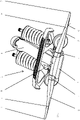
- FIG. 1 1 shows a clamp 1 according to the invention, which in the illustrated embodiment is a so-called coupling clamp, which is released during passage through a station from the cable to which it is clamped during travel on the track.
- the type of clamp is not critical to the present invention.
- the clamp can therefore also be, for example, a clamp that is detachably connected to the cable, but which is not detached from the cable while passing through a station, or a clamp that is firmly cast with the cable.
- these types of clamps are well known in the prior art, they will not be described in detail.
- clamps 1 Since a clamp 1, no matter what type, has to overlap the rope, so that it can be permanently or temporarily connected to it, it forms a bump or an obstacle for a single sheave for the rope, as well as for sheaves of a sheave battery, which generates a shock when driven over. In order to mitigate or minimize this impact, clamps 1 therefore have clamp tongues 2 which allow the rollers to run onto and off the clamp 1 more smoothly.
- the clamp tongues 2 are fixed to a fixed jaw 3 of the clamp 1.
- the rope not shown in the drawings, is clamped between a jaw 5 that can be moved via a lever 4 and the fixed part 3 of the clamp 1 .
- the terminal tongues 2 rest with their lower bearing surface 6 on the cable.
- the roller first runs onto one end 7 of a clamping tongue 2 and then rolls on a running surface 8 along the side opposite the rope to a running surface 9 on a clamp back of the clamping jaws 3, 5, whereupon it runs on the running surface 8 of the other clamping tongue 2 drains from terminal 1 again.
- the running surface 9 on the back of the clamp is used in the in 1 illustrated embodiment of the clamp 1 is formed in part by the movable jaw 5 of the clamp 1 and by the fixed jaw 3 of the clamp 1.
- the running surfaces 8, 9 are curved in section transversely to the longitudinal extension of the terminal tongues.
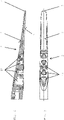
- the clamping tongues 2 have a running surface 8 that is curved essentially in an S shape in the longitudinal direction, which merges continuously or with a constant curvature into the running surface 9 of the back of the clamp .
- the running surface 8 of the clamping tongues 2 has a positive curvature Kp in the region of its free ends 8 and subsequently, ie on the side facing the clamping jaw 3, a negative curvature Kn.
- positive curvature means that the center of curvature of the running surface 8 is above the clamping tongue 2, i.e. on the side of the clamping tongue 2 facing away from the rope.
- Negative curvature therefore means that the center of curvature of the running surface 8 is on the side of the clamping tongue 2 facing the rope Terminal tongue 2 is located.
- a turning point 10 which is preferably in the area of the half of the terminal tongues 2 facing the terminal back.
- a short, straight section can also be provided, on which the turning point 10 lies.
- the running surface 9 on the back of the clamp also has a negative curvature, into which the negative curvature Kn of the running surface 8 of the clamp tongues 2 continuously transitions.
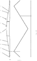
- the positive curvature Kp has a maximum approximately in the central region between the turning point 10 and the free end 7 and is essentially zero at the free end 7 of the terminal tongues.
- the positive curvature Kp increases continuously, preferably linearly, from the free end to the maximum, as in the diagram in FIG 4 is shown. This means that the radius of curvature at the end 7 of the terminal tongue 2 is essentially infinite and reaches a maximum up to the point 11 where the radius of curvature is smallest.
- the positive curvature Kp increases from the maximum Point 11 to the point of inflection 10 continuously, preferably linearly, from where it is zero again and changes into a negative curvature Kn until it again has a negative maximum in this case in the middle region 12 of the terminal back.
- the negative curvature increases continuously, preferably linearly, from the inflection point 10 to the maximum 12 on the back of the clamp.
- straight sections can be included between the individual sections with positive or negative curvature, but also within these sections.
- the positive curvature Kp from the free end of the terminal tongue to the maximum 11 increases more than it decreases from the maximum 11 to the inflection point 10 and if the negative curvature from the inflection point 10 to the maximum 12 on the back of the clamp increases less strongly than from the free end 7 of the terminal tongue 2 to the maximum 11 on the terminal tongue.
- the increase and decrease could be implemented differently everywhere or only in sections.
- the terminal tongues 2 are preferably made of plastic, with recesses 13 being able to be provided in their base body to save weight and/or to improve the elastic or damping properties.
- the free ends 7 of the terminal tongues are preferably rounded, with the positive curvature Kp adjoining the rounded area.
Landscapes
- Engineering & Computer Science (AREA)
- Transportation (AREA)
- Mechanical Engineering (AREA)
- Clamps And Clips (AREA)
- Installation Of Indoor Wiring (AREA)
- Electric Cable Installation (AREA)
- Automobile Manufacture Line, Endless Track Vehicle, Trailer (AREA)
- Forklifts And Lifting Vehicles (AREA)
- Light Guides In General And Applications Therefor (AREA)
- Vehicle Cleaning, Maintenance, Repair, Refitting, And Outriggers (AREA)
- Electric Cable Arrangement Between Relatively Moving Parts (AREA)
Description
- Die Erfindung betrifft eine Klemme für ein seilgezogenes Fahrbetriebsmittel mit einem Klemmenrücken und daran anschließenden Klemmenzungen, wobei der Klemmenrücken und die Klemmenzungen Laufflächen für Rollen aufweisen.
- Die Erfindung betrifft des Weiteren ein seilgezogenes Fahrbetriebsmittel, beispielsweise einen Sessel eines Sessellifts oder eine Seilbahnkabine, mit einem Aufnahmebereich für Personen und/oder Gegenstände und einer Verbindungseinrichtung zum Verbinden des Aufnahmebereichs mit einem Seil, sowie eine Seilbahnanlage mit wenigstens zwei Stationen, wobei zwischen den Stationen mit einem Seil verbundene Fahrbetriebsmittel fahrbar sind.
- Bei Seilbahnen werden in vielen Fällen zwischen Stationen Stützen mit Rollenbatterien verwendet, wobei diese Rollenbatterien von den Klemmen zum Teil überfahren und zum Teil unterfahren werden. Das heißt, dass die Klemmen der Fahrbetriebsmittel über die Rollen der Rollenbatterien hinweg oder unter diesen durch bewegt werden. Die Klemmen sind dabei in der Regel so ausgeführt, dass sie das Seil von oben übergreifen, wodurch die Klemmen den unteren Bereich des Seiles weniger überragen als den oberen Bereich und folglich beim Überfahren einer Rollenbatterie weniger störend wirken als beim Unterfahren. Es ist allerdings auch möglich, dass die Klemmen den unteren Bereich des Seiles übergreifen, wobei die Erfindung auch für derartige Klemmen uneingeschränkt anwendbar ist.
- Dies hat zur Folge, dass beim Unterfahren einer Rollenbatterie nicht nur die einzelnen Komponenten der Rollenbatterie mechanisch stärker belastet werden, sondern auch die Komponenten der Fahrbetriebsmittel und die Erschütterungen überdies von Fahrgästen als unangenehm empfunden werden.
- Um den negativen Einfluss dieser Erschütterungen zu verkleinern, weisen Klemmen für seilgezogene Fahrbetriebsmittel daher sogenannte Klemmenzungen auf, welche sich im oberen Bereich des Seiles bzw. der Klemmen in Längsrichtung des Seils vor und nach den Klemmen erstrecken um ein sanfteres Auflaufen der Rollen auf den Klemmenrücken und Ablaufen vom Klemmenrücken zu ermöglichen, wenn die Klemmen unter den Rollen durch bewegt werden.
-
EP 0 132 721 A1 undFR 2 675 451 A1 - Der Erfindung liegt die Aufgabe zugrunde, die Geometrie dieser Klemmenzungen zu verbessern, damit ein möglichst sanfter Abrollvorgang der Rollen über den Klemmenrücken ermöglicht wird. Gelöst wird diese Aufgabe mit einer Klemme mit den Merkmalen des Anspruchs 1.
- Durch die S-förmig gekrümmte Lauffläche der Klemmenzungen und den kontinuierlichen bzw. krümmungsstetigen Übergang in die Lauffläche des Klemmenrückens wird das dynamische Systemverhalten, d.h. das Zusammenwirken der Rollen bzw. Rollenbatterien mit den Klemmen am Seil optimiert, indem abrupte Beschleunigungen der Systemkomponenten beim Unterfahren einer Niederhalte-Rollenbatterie verringert werden.
- Die Lauffläche der Klemmenzungen weist erfindungsgemäß im Bereich ihrer freien Enden eine positive Krümmung und darauffolgend eine negative Krümmung auf, wobei bevorzugt ein Wendepunkt zwischen diesen Krümmungen liegt.
- Dabei ist weiters bevorzugt, wenn die positive Krümmung im Mittelbereich zwischen dem Wendepunkt und dem freien Ende ein Maximum aufweist bzw. die positive Krümmung am freien Ende der Klemmenzunge im Wesentlichen Null ist.
- Auf diese Weise wird ein kontinuierliches Beschleunigungsverhalten der über die Klemme und die Klemmenzungen rollenden Laufrollen der Rollenbatterien und der Klemme mit dem Fahrbetriebsmittel bewirkt.
- Weitere bevorzugte Ausführungsformen der Erfindung sind Gegenstand der übrigen Unteransprüche.
- Weitere Merkmale und Vorteile der Erfindung ergeben sich aus der nachfolgenden Beschreibung bevorzugter Ausführungsformen der Erfindung unter Bezugnahme auf die angeschlossenen Zeichnungen. Es zeigt:
- Fig. 1
- eine Ausführungsform einer erfindungsgemäßen Klemme mit Klemmenzungen in Form einer Kuppelklemme,
- Fig. 2
- eine Ausführungsform einer Klemmenzunge im Schnitt,
- Fig. 3
- eine Ansicht auf die Klemmenzunge von
Fig. 2 von unten, und - Fig. 4
- ein Diagramm, das den Verlauf der Krümmung über die Länge der Klemme mit den Klemmenzungen zeigt.
- In
Fig. 1 ist eine erfindungsgemäße Klemme 1 gezeigt, die in der dargestellten Ausführungsform eine sogenannte Kuppelklemme ist, welche während der Durchfahrt durch eine Station vom Seil, an das sie während der Fahrt auf der Strecke geklemmt ist, gelöst wird. Die Art der Klemme ist für die vorliegenden Erfindung jedoch nicht wesentlich. Die Klemme kann daher beispielsweise auch eine zwar lösbar mit dem Seil verbundene Klemme sein, die aber während der Durchfahrt durch eine Station nicht vom Seil gelöst wird, oder eine fest mit dem Seil vergossene Klemme. Da diese Arten von Klemmen überdies aus dem Stand der Technik hinlänglich bekannt sind, werden diese nicht näher beschrieben. - Da eine Klemme 1, egal welcher Art, das Seil übergreifen muss, damit sie damit dauerhaft oder temporär verbunden werden kann, bildet sie für eine einzelne Rolle für das Seil, ebenso wie für Rollen einer Rollenbatterie, eine Erhebung bzw. ein Hindernis, das beim Überfahren einen Stoß erzeugt. Um diesen Stoß zu mildern bzw. zu minimieren, weisen Klemmen 1 daher Klemmenzungen 2 auf, die ein sanfteres Auflaufen der Rollen auf die Klemme 1 und Ablaufen von der Klemme 1 zu ermöglichen.
- Wenn die Klemme 1 wie in der dargestellten Ausführungsform eine Kuppelklemme ist, sind die Klemmenzungen 2 an einer feststehenden Klemmbacke 3 der Klemme 1 befestigt. Das in den Zeichnungen nicht dargestellte Seil wird zwischen einer über einen Hebel 4 beweglichen Klemmbacke 5 und dem feststehenden Teil 3 der Klemme 1 geklemmt. Die Klemmenzungen 2 liegen mit ihrer unteren Auflagefläche 6 auf dem Seil auf.
- Wenn die Klemme 1 eine Rolle überfährt, kommen nur die Klemmbacken 3, 5 im Bereich ihrer unteren Ränder in Kontakt mit der Rolle, wobei der auftretende Stoß erheblich kleiner ist, als wenn eine Rolle mit der Klemme 1 unterfahren wird, da die Klemme 1 die Oberseite des Seiles erheblich überragt. Die Rolle läuft dabei zunächst auf ein Ende 7 einer Klemmenzunge 2 auf und rollt dann auf einer Lauffläche 8 an der dem Seil gegenüberliegenden Seite entlang bis über eine Lauffläche 9 an einem Klemmenrücken der Klemmbacken 3, 5, worauf sie an der Lauffläche 8 der anderen Klemmenzunge 2 wieder von der Klemme 1 abläuft. Die Lauffläche 9 am Klemmenrücken wird bei der in
Fig. 1 dargestellten Ausführungsform der Klemme 1 zum Teil von der beweglichen Klemmbacke 5 der Klemme 1 als auch von der feststehenden Klemmbacke 3 der Klemme 1 gebildet. Die Laufflächen 8, 9 sind im Schnitt quer zur Längserstreckung der Klemmenzungen gekrümmt. - Damit die Rolle möglichst stoßfrei über die Laufflächen 8, 9 an den Klemmenzungen 2 und dem Klemmenrücken laufen kann, weisen die Klemmenzungen 2 in Längsrichtung eine im Wesentlichen S-förmig gekrümmte Lauffläche 8 auf, welche kontinuierlich bzw. krümmungsstetig in die Lauffläche 9 des Klemmenrückens übergeht.
- Die Lauffläche 8 der Klemmenzungen 2 weist im Bereich ihrer freien Enden 8 eine positive Krümmung Kp und darauf folgend, also auf der der Klemmbacke 3 zugewandten Seite eine negative Krümmung Kn auf. Positive Krümmung bedeutet im Rahmen der vorliegenden Erfindung, dass der Krümmungsmittelpunkt der Lauffläche 8 über der Klemmenzunge 2 liegt, also auf der vom Seil abgewandten Seite der Klemmenzunge 2. Negative Krümmung bedeutet daher, dass der Krümmungsmittelpunkt der Lauffläche 8 auf der dem Seil zugewandten Seite der Klemmenzunge 2 liegt.
- Zwischen diesen Krümmungen Kp, Kn liegt ein Wendepunkt 10, der bevorzugt im Bereich der dem Klemmenrücken zugewandten Hälfte der Klemmenzungen 2 liegt. Es kann aber auch ein kurzer gerader Abschnitt vorgesehen sein, auf dem der Wendepunkt 10 liegt.
- Die Lauffläche 9 am Klemmenrücken weist ebenfalls eine negative Krümmung auf, in welche die negative Krümmung Kn der Lauffläche 8 der Klemmenzungen 2 kontinuierlich übergeht.
- In Verbindung mit
Fig. 4 wird eine besonders bevorzugte Ausführungsform der Krümmung der Laufflächen 8, 9 beschrieben, mit der ein besonders sanftes Abrollen der Rollen einer Rollenbatterie auf der Klemme 1 ermöglicht wird, wobei einzelne oder mehrere der nachfolgend beschriebenen Details der Krümmung auch anders ausgeführt werden können. - Die positive Krümmung Kp weist etwa im Mittelbereich zwischen dem Wendepunkt 10 und dem freien Ende 7 ein Maximum auf und ist am freien Ende 7 der Klemmenzungen im Wesentlichen Null. Die positive Krümmung Kp nimmt vom freien Ende zum Maximum hin kontinuierlich, vorzugsweise linear, zu, wie im Diagramm von
Fig. 4 dargestellt ist. Das heißt, dass der Krümmungsradius am Ende 7 der Klemmenzunge 2 im Wesentlichen unendlich ist und bis zum Punkt 11, an dem der Krümmungsradius am kleinsten ist, ein Maximum erreicht. - In weiterer Folge nimmt die positive Krümmung Kp vom Maximum am Punkt 11 zum Wendepunkt 10 hin kontinuierlich, vorzugsweise linear, ab, ist dort wieder Null und geht in eine negative Krümmung Kn über, bis sie im Mittelbereich 12 des Klemmenrückens wieder ein in diesem Fall negatives Maximum aufweist. Auch hier nimmt die negative Krümmung vom Wendepunkt 10 zum Maximum 12 am Klemmenrücken hin kontinuierlich, vorzugsweise linear, zu.
- Wenngleich eine lineare Zu- und Abnahme bevorzugt ist, könnte diese überall oder auch nur abschnittsweise nicht linear zu- und/oder abnehmen. Des Weiteren können zwischen den einzelnen Abschnitten mit positiver bzw. negativer Krümmung, aber auch innerhalb dieser Abschnitte, gerade Abschnitte enthalten sein.
- Bei der Erfindung ist weiters bevorzugt, wenn die positive Krümmung Kp vom freien Ende der Klemmenzunge zum Maximum 11 hin stärker zunimmt als sie vom Maximum 11 zum Wendepunkt 10 hin abnimmt und wenn die negative Krümmung vom Wendepunkt 10 zum Maximum 12 am Klemmenrücken hin weniger stark zunimmt als vom freien Ende 7 der Klemmenzunge 2 zum Maximum 11 an der Klemmenzunge. Auch hier könnte die Zu- und Abnahme überall oder auch nur abschnittsweise anders ausgeführt sein.
- Die Klemmenzungen 2 sind bevorzugt aus Kunststoff ausgeführt, wobei in deren Grundkörper aus Gründen der Gewichtsersparnis und/oder zur Verbesserung der elastischen bzw. dämpfenden Eigenschaften Ausnehmungen 13 angebracht sein können. Die freien Enden 7 der Klemmenzungen sind bevorzugt abgerundet, wobei die positive Krümmung Kp an den abgerundeten Bereich anschließt.
Claims (17)
- Klemme für ein seilgezogenes Fahrbetriebsmittel mit Klemmbacken (3, 5) mit einem Klemmenrücken und daran anschließenden Klemmenzungen (2), wobei der Klemmenrücken und die Klemmenzungen (2) Laufflächen (8, 9) für Rollen aufweisen, wobei die Klemmenzungen (2) in Längsrichtung eine im Wesentlichen S-förmig gekrümmte Lauffläche (8) aufweisen, welche kontinuierlich bzw. krümmungsstetig in die Lauffläche (9) des Klemmenrückens übergeht, und wobei die Lauffläche (8) der Klemmenzungen (2) im Bereich ihrer freien Enden (7) eine positive Krümmung (Kp) und darauf folgend eine negative Krümmung (Kn) aufweist, dadurch gekennzeichnet, dass die Lauffläche (9) am Klemmenrücken eine negative Krümmung (Kn) aufweist, und dass die negative Krümmung (Kn) im Mittelbereich des Klemmenrückens ein Maximum (12) aufweist.
- Klemme nach Anspruch 1, dadurch gekennzeichnet, dass ein Wendepunkt (10) zwischen diesen Krümmungen (Kp, Kn) liegt.
- Klemme nach Anspruch 2, dadurch gekennzeichnet, dass der Wendepunkt (10) im Bereich der dem Klemmenrücken zugewandten Hälfte der Klemmenzungen (2) liegt.
- Klemme nach Anspruch 2 oder 3, dadurch gekennzeichnet, dass die positive Krümmung (Kp) ein Maximum (11) aufweist, das vorzugsweise im Mittelbereich, besonders bevorzugt in der Mitte, zwischen dem Wendepunkt (10) und dem freien Ende (7) liegt.
- Klemme nach einem der Ansprüche 1 bis 4, dadurch gekennzeichnet, dass die positive Krümmung (Kp) am freien Ende (7) der Klemmenzungen (2) im Wesentlichen Null ist.
- Klemme nach einem der Ansprüche 1 bis 5, dadurch gekennzeichnet, dass die freien Enden (7) der Klemmenzungen (2) abgerundet sind, und dass die positive Krümmung (Kp) an den abgerundeten Bereich mit vorzugsweise negativer Krümmung anschließt.
- Klemme nach einem der Ansprüche 4 bis 6, dadurch gekennzeichnet, dass die positive Krümmung (Kp) vom freien Ende (7) zum Maximum (11) an der Klemmenzunge (2) hin kontinuierlich, vorzugsweise linear, zunimmt.
- Klemme nach einem der Ansprüche 4 bis 7, dadurch gekennzeichnet, dass die positive Krümmung (Kp) vom Maximum (11) an der Klemmenzunge (2) zum Wendepunkt (10) hin kontinuierlich, vorzugsweise linear, abnimmt.
- Klemme nach einem der Ansprüche 1 bis 8, dadurch gekennzeichnet, dass die negative Krümmung (Kn) vom Wendepunkt (10) zum Maximum (12) am Klemmenrücken hin kontinuierlich, vorzugsweise linear, zunimmt.
- Klemme nach einem der Ansprüche 8 oder 9, dadurch gekennzeichnet, dass die positive Krümmung (Kp) vom freien Ende (7) der Klemmenzunge (2) zum Maximum (11) an der Klemmenzunge (2) hin stärker zunimmt als sie vom Maximum (11) an der Klemmenzunge (2) zum Wendepunkt (10) hin abnimmt.
- Klemme nach einem der Ansprüche 1 bis 10, dadurch gekennzeichnet, dass die negative Krümmung (Kn) vom Wendepunkt (10) zum Maximum (12) am Klemmenrücken hin weniger stark zunimmt als vom freien Ende (7) der Klemmenzunge (2) zum Maximum (11) an der Klemmenzunge (2).
- Klemme nach einem der Ansprüche 1 bis 11, dadurch gekennzeichnet, dass die Klemmenzungen (2) eine Auflagefläche (6) für ein Seil aufweisen, welche der Lauffläche (8) gegenüber liegt.
- Klemme nach Anspruch 12, dadurch gekennzeichnet, dass die Klemmenzungen (2) im Bereich der Auflagefläche (6) wenigstens eine Ausnehmung (13) aufweisen.
- Klemme nach einem der Ansprüche 1 bis 13, dadurch gekennzeichnet, dass sie zwei Klemmbacken (3, 5) aufweist, von denen eine Klemmbacke (3) unbeweglich und mit den Klemmenzungen (2) verbunden ist.
- Klemme nach einem der Ansprüche 1 bis 14, dadurch gekennzeichnet, dass zwischen den einzelnen Abschnitten mit positiver bzw. negativer Krümmung (Kp, Kn) und/oder innerhalb dieser Abschnitte gerade Abschnitte enthalten sind.
- Seilgezogenes Fahrbetriebsmittel mit einem Aufnahmebereich für Personen und/oder Gegenstände und einer Verbindungseinrichtung zum Verbinden des Aufnahmebereichs mit einem Seil, dadurch gekennzeichnet, dass die Verbindungseinrichtung eine Klemme (1) nach einem der Ansprüche 1 bis 15 aufweist.
- Seilbahnanlage mit wenigstens zwei Stationen, wobei zwischen den Stationen mit einem Seil verbundene Fahrbetriebsmittel fahrbar sind, dadurch gekennzeichnet, dass die Fahrbetriebsmittel eine Klemme (1) nach einem der Ansprüche 1 bis 15 aufweisen.
Applications Claiming Priority (2)
| Application Number | Priority Date | Filing Date | Title |
|---|---|---|---|
| ATA677/2015A AT517919B1 (de) | 2015-10-19 | 2015-10-19 | Klemme |
| PCT/EP2016/072444 WO2017067731A1 (de) | 2015-10-19 | 2016-09-21 | Klemme |
Publications (2)
| Publication Number | Publication Date |
|---|---|
| EP3365214A1 EP3365214A1 (de) | 2018-08-29 |
| EP3365214B1 true EP3365214B1 (de) | 2022-08-03 |
Family
ID=56958951
Family Applications (1)
| Application Number | Title | Priority Date | Filing Date |
|---|---|---|---|
| EP16767320.1A Active EP3365214B1 (de) | 2015-10-19 | 2016-09-21 | Klemme |
Country Status (21)
| Country | Link |
|---|---|
| US (1) | US10723368B2 (de) |
| EP (1) | EP3365214B1 (de) |
| JP (1) | JP6648269B2 (de) |
| KR (1) | KR102049968B1 (de) |
| CN (1) | CN108137064A (de) |
| AR (1) | AR106396A1 (de) |
| AT (1) | AT517919B1 (de) |
| AU (1) | AU2016343567B2 (de) |
| BR (1) | BR112018006889B1 (de) |
| CA (1) | CA3000876C (de) |
| CL (1) | CL2018000921A1 (de) |
| CO (1) | CO2018003773A2 (de) |
| ES (1) | ES2926492T3 (de) |
| MA (1) | MA44385A (de) |
| MX (1) | MX387192B (de) |
| NZ (1) | NZ741331A (de) |
| PE (1) | PE20180973A1 (de) |
| PL (1) | PL3365214T3 (de) |
| RU (1) | RU2694682C1 (de) |
| TN (1) | TN2018000107A1 (de) |
| WO (1) | WO2017067731A1 (de) |
Families Citing this family (3)
| Publication number | Priority date | Publication date | Assignee | Title |
|---|---|---|---|---|
| AT517873B1 (de) * | 2015-10-15 | 2019-04-15 | C D C Chain Drive Crane Gmbh | Seilbahnlaufwagen |
| AT517919B1 (de) * | 2015-10-19 | 2020-12-15 | Innova Patent Gmbh | Klemme |
| FR3161182A1 (fr) | 2024-04-15 | 2025-10-17 | Mnd France | Dispositif d’accouplement débrayable pour véhicule d’installation de transport aérien comprenant deux aiguilles chacune en deux parties |
Citations (1)
| Publication number | Priority date | Publication date | Assignee | Title |
|---|---|---|---|---|
| JPH03292252A (ja) * | 1990-04-06 | 1991-12-24 | Mitsubishi Heavy Ind Ltd | 握索装置のリードハンガー装置 |
Family Cites Families (20)
| Publication number | Priority date | Publication date | Assignee | Title |
|---|---|---|---|---|
| US3037464A (en) * | 1960-04-12 | 1962-06-05 | J W Penney & Sons Co | Cable grip |
| FR2036543A5 (de) * | 1969-03-27 | 1970-12-24 | Alsthom | |
| DE2652315A1 (de) | 1976-11-17 | 1978-05-18 | Seilwolff Ag | Vorrichtung zur beweglichen befestigung von kraftableitern an einem drahtseil |
| FR2506245B1 (fr) * | 1981-05-20 | 1985-06-14 | Montaz Mautino Ets | Perfectionnement aux installations de transport par cable |
| FR2549430B1 (fr) * | 1983-07-21 | 1986-03-21 | Grenoble Inst Nal Polytechni | Dispositif de fixation d'une telecabine ou d'un telesiege sur un cable muni d'une surface de roulement pour galets |
| SU1382705A1 (ru) | 1985-03-25 | 1988-03-23 | Научно-Исследовательский И Проектно-Конструкторский Институт По Специальным Видам Транспорта И Системам Автоматизации | Канатный зажим подвесной канатной дороги |
| JPH0635851Y2 (ja) | 1989-08-21 | 1994-09-21 | 東レエンジニアリング株式会社 | 握索装置 |
| FR2661880B1 (fr) | 1990-05-10 | 1992-08-07 | Bourgogne Plastiques | Dispositif de remontee mecanique pour petits vehicules, du genre luges. |
| SU1773763A1 (ru) | 1990-08-22 | 1992-11-07 | Proizv Ob Sp Transportu Sistem | Kahathый зaжиm пoдbechoй kahathoй дopoги |
| JP2574602Y2 (ja) | 1990-08-22 | 1998-06-18 | 日本ケーブル株式会社 | 索道の固定式握索機のタング装置 |
| FR2675451B1 (fr) | 1991-04-17 | 1994-05-13 | Pomagalski Sa | Dispositif d'entrainement et de commande d'une pince d'un teleporteur. |
| JPH05162637A (ja) | 1991-12-17 | 1993-06-29 | Mitsubishi Heavy Ind Ltd | 搬器用索道 |
| AT404458B (de) | 1993-03-30 | 1998-11-25 | Doppelmayr & Sohn | Vorrichtung zum ankuppeln eines fahrbetriebsmittels |
| FR2768112B1 (fr) | 1997-09-08 | 1999-11-05 | Noel Duffour | Dispositif de graissage pour equipements depylones de remontee mecanique |
| CN2853533Y (zh) * | 2005-12-14 | 2007-01-03 | 何盛 | 弧形固定抱索器 |
| RU2471663C1 (ru) | 2011-07-12 | 2013-01-10 | Общество с ограниченной ответственностью "Инженерно-консультационный центр "Мысль" Новочеркасского государственного технического университета | Канатное зажимное устройство с электромагнитным приводом для отцепляемого подвижного состава подвесной канатной дороги |
| CO7030190A1 (es) | 2013-02-12 | 2014-08-21 | Univ Eafit | Sistema de monitoreo de la condición de circulación de vehiculos en el punto de conexión y operación entre el cable, la cabina, la estación y la pinza soporte en un sistema de transporte de tracción por cable |
| CN203651755U (zh) | 2013-12-03 | 2014-06-18 | 湖南永安煤矿机械制造有限公司 | 一种可摘挂抱索器 |
| CN104787054B (zh) | 2015-04-28 | 2017-03-15 | 北京中索国游索道工程技术有限公司 | 脱挂抱索器 |
| AT517919B1 (de) * | 2015-10-19 | 2020-12-15 | Innova Patent Gmbh | Klemme |
-
2015
- 2015-10-19 AT ATA677/2015A patent/AT517919B1/de not_active IP Right Cessation
-
2016
- 2016-09-21 EP EP16767320.1A patent/EP3365214B1/de active Active
- 2016-09-21 PL PL16767320.1T patent/PL3365214T3/pl unknown
- 2016-09-21 KR KR1020187014264A patent/KR102049968B1/ko not_active Expired - Fee Related
- 2016-09-21 TN TNP/2018/000107A patent/TN2018000107A1/en unknown
- 2016-09-21 AU AU2016343567A patent/AU2016343567B2/en not_active Ceased
- 2016-09-21 CA CA3000876A patent/CA3000876C/en active Active
- 2016-09-21 PE PE2018000542A patent/PE20180973A1/es unknown
- 2016-09-21 US US15/769,384 patent/US10723368B2/en active Active
- 2016-09-21 WO PCT/EP2016/072444 patent/WO2017067731A1/de not_active Ceased
- 2016-09-21 BR BR112018006889-6A patent/BR112018006889B1/pt not_active IP Right Cessation
- 2016-09-21 NZ NZ741331A patent/NZ741331A/en not_active IP Right Cessation
- 2016-09-21 MA MA044385A patent/MA44385A/fr unknown
- 2016-09-21 RU RU2018118322A patent/RU2694682C1/ru active
- 2016-09-21 CN CN201680061103.6A patent/CN108137064A/zh active Pending
- 2016-09-21 JP JP2018520161A patent/JP6648269B2/ja not_active Expired - Fee Related
- 2016-09-21 MX MX2018004375A patent/MX387192B/es unknown
- 2016-09-21 ES ES16767320T patent/ES2926492T3/es active Active
- 2016-10-19 AR ARP160103178A patent/AR106396A1/es active IP Right Grant
-
2018
- 2018-04-10 CO CONC2018/0003773A patent/CO2018003773A2/es unknown
- 2018-04-11 CL CL2018000921A patent/CL2018000921A1/es unknown
Patent Citations (1)
| Publication number | Priority date | Publication date | Assignee | Title |
|---|---|---|---|---|
| JPH03292252A (ja) * | 1990-04-06 | 1991-12-24 | Mitsubishi Heavy Ind Ltd | 握索装置のリードハンガー装置 |
Also Published As
| Publication number | Publication date |
|---|---|
| WO2017067731A1 (de) | 2017-04-27 |
| MX2018004375A (es) | 2018-08-01 |
| AU2016343567A1 (en) | 2018-04-26 |
| NZ741331A (en) | 2019-03-29 |
| CA3000876C (en) | 2020-01-07 |
| BR112018006889A2 (pt) | 2018-10-16 |
| AU2016343567B2 (en) | 2019-11-07 |
| CN108137064A (zh) | 2018-06-08 |
| RU2694682C1 (ru) | 2019-07-16 |
| TN2018000107A1 (en) | 2019-10-04 |
| BR112018006889B1 (pt) | 2023-03-21 |
| PL3365214T3 (pl) | 2022-12-12 |
| KR102049968B1 (ko) | 2019-11-28 |
| AT517919B1 (de) | 2020-12-15 |
| CO2018003773A2 (es) | 2018-05-31 |
| MA44385A (fr) | 2019-01-23 |
| KR20180071338A (ko) | 2018-06-27 |
| JP6648269B2 (ja) | 2020-02-14 |
| AR106396A1 (es) | 2018-01-10 |
| EP3365214A1 (de) | 2018-08-29 |
| US10723368B2 (en) | 2020-07-28 |
| AT517919A1 (de) | 2017-05-15 |
| CA3000876A1 (en) | 2017-04-27 |
| PE20180973A1 (es) | 2018-06-14 |
| MX387192B (es) | 2025-03-18 |
| CL2018000921A1 (es) | 2018-06-01 |
| JP2018532639A (ja) | 2018-11-08 |
| US20180304908A1 (en) | 2018-10-25 |
| ES2926492T3 (es) | 2022-10-26 |
Similar Documents
| Publication | Publication Date | Title |
|---|---|---|
| EP2855970B1 (de) | Gurtendekörper oder gurtsegmentendekörper | |
| EP3362332B1 (de) | Seilbahnlaufwagen | |
| AT517919B1 (de) | Klemme | |
| EP1744976B1 (de) | Transportvorrichtung mit transportband | |
| DE19958734B4 (de) | Sturzsicherungssystem und Trolley zur Anwendung in einem solchen System | |
| DE102010032004A1 (de) | Klemm- und Zugvorrichtung | |
| EP3820797B1 (de) | Fördereinrichtung mit mindestens zwei förderwagen und einer antriebsstrangbremse für einen quergurtförderer an mindestens einem der förderwagen | |
| EP3569426A1 (de) | System zur führung von leitungen in einem fahrzeug, insbesondere in einem fahrzeug mit beweglich miteinander verbundenen fahrzeugteilen | |
| DE102011004783A1 (de) | Transportvorrichtung | |
| CH644821A5 (de) | Rollenfuehrungsschuh fuer aufzuege. | |
| EP3833881B1 (de) | Melkkarussell mit einem tragwagen | |
| DE202020102988U1 (de) | Werkstückträgersystem | |
| DE102008033268A1 (de) | Transportvorrichtung und Transportverfahren zum Transport von Fahrzeugreifen | |
| AT510367A1 (de) | Fahrdrahtklemme für oberleitungskreuzungen | |
| DE102019129920A1 (de) | Vorrichtung zum Stoppen und Vereinzeln von länglichen Werkstücken | |
| DE102006045575A1 (de) | Werkstückträgereinrichtung sowie Friktionsförderer | |
| AT409254B (de) | Laufrolle für das fahrwerk des fahrbetriebsmittels einer seilbahnanlage | |
| WO2014206878A1 (de) | Abdichteinrichtung für eine bandübergabe | |
| EP1174325B1 (de) | Fahrwerk für das Fahrbetriebsmittel einer Seilbahnanlage | |
| DE811021C (de) | Laufkatze | |
| EP1332939B1 (de) | Seilreiter | |
| DE102008000385B4 (de) | Verfahren zur Verwendung einer Rücklaufsperre für eine Bahneinziehvorrichtung | |
| DE2121234A1 (de) | Platten Forderband | |
| DE2601876A1 (de) | Vorrichtung zur fuehrung des beweglichen tisches einer werkzeugmaschine | |
| DE102015202819A1 (de) | Fördersystem |
Legal Events
| Date | Code | Title | Description |
|---|---|---|---|
| STAA | Information on the status of an ep patent application or granted ep patent |
Free format text: STATUS: THE INTERNATIONAL PUBLICATION HAS BEEN MADE |
|
| PUAI | Public reference made under article 153(3) epc to a published international application that has entered the european phase |
Free format text: ORIGINAL CODE: 0009012 |
|
| STAA | Information on the status of an ep patent application or granted ep patent |
Free format text: STATUS: REQUEST FOR EXAMINATION WAS MADE |
|
| 17P | Request for examination filed |
Effective date: 20180515 |
|
| AK | Designated contracting states |
Kind code of ref document: A1 Designated state(s): AL AT BE BG CH CY CZ DE DK EE ES FI FR GB GR HR HU IE IS IT LI LT LU LV MC MK MT NL NO PL PT RO RS SE SI SK SM TR |
|
| AX | Request for extension of the european patent |
Extension state: BA ME |
|
| DAX | Request for extension of the european patent (deleted) | ||
| RAV | Requested validation state of the european patent: fee paid |
Extension state: MA Effective date: 20180515 |
|
| STAA | Information on the status of an ep patent application or granted ep patent |
Free format text: STATUS: EXAMINATION IS IN PROGRESS |
|
| 17Q | First examination report despatched |
Effective date: 20201020 |
|
| GRAP | Despatch of communication of intention to grant a patent |
Free format text: ORIGINAL CODE: EPIDOSNIGR1 |
|
| STAA | Information on the status of an ep patent application or granted ep patent |
Free format text: STATUS: GRANT OF PATENT IS INTENDED |
|
| INTG | Intention to grant announced |
Effective date: 20220225 |
|
| GRAS | Grant fee paid |
Free format text: ORIGINAL CODE: EPIDOSNIGR3 |
|
| GRAA | (expected) grant |
Free format text: ORIGINAL CODE: 0009210 |
|
| STAA | Information on the status of an ep patent application or granted ep patent |
Free format text: STATUS: THE PATENT HAS BEEN GRANTED |
|
| AK | Designated contracting states |
Kind code of ref document: B1 Designated state(s): AL AT BE BG CH CY CZ DE DK EE ES FI FR GB GR HR HU IE IS IT LI LT LU LV MC MK MT NL NO PL PT RO RS SE SI SK SM TR |
|
| REG | Reference to a national code |
Ref country code: AT Ref legal event code: REF Ref document number: 1508520 Country of ref document: AT Kind code of ref document: T Effective date: 20220815 Ref country code: CH Ref legal event code: EP |
|
| REG | Reference to a national code |
Ref country code: DE Ref legal event code: R096 Ref document number: 502016015140 Country of ref document: DE |
|
| REG | Reference to a national code |
Ref country code: IE Ref legal event code: FG4D Free format text: LANGUAGE OF EP DOCUMENT: GERMAN |
|
| REG | Reference to a national code |
Ref country code: FI Ref legal event code: FGE |
|
| REG | Reference to a national code |
Ref country code: SE Ref legal event code: TRGR |
|
| REG | Reference to a national code |
Ref country code: NO Ref legal event code: T2 Effective date: 20220803 |
|
| REG | Reference to a national code |
Ref country code: ES Ref legal event code: FG2A Ref document number: 2926492 Country of ref document: ES Kind code of ref document: T3 Effective date: 20221026 |
|
| PGFP | Annual fee paid to national office [announced via postgrant information from national office to epo] |
Ref country code: TR Payment date: 20220909 Year of fee payment: 7 Ref country code: SE Payment date: 20220923 Year of fee payment: 7 Ref country code: NO Payment date: 20220921 Year of fee payment: 7 Ref country code: FI Payment date: 20220920 Year of fee payment: 7 |
|
| REG | Reference to a national code |
Ref country code: LT Ref legal event code: MG9D |
|
| REG | Reference to a national code |
Ref country code: NL Ref legal event code: MP Effective date: 20220803 |
|
| PG25 | Lapsed in a contracting state [announced via postgrant information from national office to epo] |
Ref country code: RS Free format text: LAPSE BECAUSE OF FAILURE TO SUBMIT A TRANSLATION OF THE DESCRIPTION OR TO PAY THE FEE WITHIN THE PRESCRIBED TIME-LIMIT Effective date: 20220803 Ref country code: PT Free format text: LAPSE BECAUSE OF FAILURE TO SUBMIT A TRANSLATION OF THE DESCRIPTION OR TO PAY THE FEE WITHIN THE PRESCRIBED TIME-LIMIT Effective date: 20221205 Ref country code: NL Free format text: LAPSE BECAUSE OF FAILURE TO SUBMIT A TRANSLATION OF THE DESCRIPTION OR TO PAY THE FEE WITHIN THE PRESCRIBED TIME-LIMIT Effective date: 20220803 Ref country code: LV Free format text: LAPSE BECAUSE OF FAILURE TO SUBMIT A TRANSLATION OF THE DESCRIPTION OR TO PAY THE FEE WITHIN THE PRESCRIBED TIME-LIMIT Effective date: 20220803 Ref country code: LT Free format text: LAPSE BECAUSE OF FAILURE TO SUBMIT A TRANSLATION OF THE DESCRIPTION OR TO PAY THE FEE WITHIN THE PRESCRIBED TIME-LIMIT Effective date: 20220803 |
|
| PGFP | Annual fee paid to national office [announced via postgrant information from national office to epo] |
Ref country code: CZ Payment date: 20220919 Year of fee payment: 7 |
|
| PG25 | Lapsed in a contracting state [announced via postgrant information from national office to epo] |
Ref country code: IS Free format text: LAPSE BECAUSE OF FAILURE TO SUBMIT A TRANSLATION OF THE DESCRIPTION OR TO PAY THE FEE WITHIN THE PRESCRIBED TIME-LIMIT Effective date: 20221203 Ref country code: HR Free format text: LAPSE BECAUSE OF FAILURE TO SUBMIT A TRANSLATION OF THE DESCRIPTION OR TO PAY THE FEE WITHIN THE PRESCRIBED TIME-LIMIT Effective date: 20220803 Ref country code: GR Free format text: LAPSE BECAUSE OF FAILURE TO SUBMIT A TRANSLATION OF THE DESCRIPTION OR TO PAY THE FEE WITHIN THE PRESCRIBED TIME-LIMIT Effective date: 20221104 |
|
| PGFP | Annual fee paid to national office [announced via postgrant information from national office to epo] |
Ref country code: PL Payment date: 20220825 Year of fee payment: 7 |
|
| PG25 | Lapsed in a contracting state [announced via postgrant information from national office to epo] |
Ref country code: SM Free format text: LAPSE BECAUSE OF FAILURE TO SUBMIT A TRANSLATION OF THE DESCRIPTION OR TO PAY THE FEE WITHIN THE PRESCRIBED TIME-LIMIT Effective date: 20220803 Ref country code: RO Free format text: LAPSE BECAUSE OF FAILURE TO SUBMIT A TRANSLATION OF THE DESCRIPTION OR TO PAY THE FEE WITHIN THE PRESCRIBED TIME-LIMIT Effective date: 20220803 Ref country code: DK Free format text: LAPSE BECAUSE OF FAILURE TO SUBMIT A TRANSLATION OF THE DESCRIPTION OR TO PAY THE FEE WITHIN THE PRESCRIBED TIME-LIMIT Effective date: 20220803 |
|
| REG | Reference to a national code |
Ref country code: DE Ref legal event code: R097 Ref document number: 502016015140 Country of ref document: DE |
|
| REG | Reference to a national code |
Ref country code: BE Ref legal event code: MM Effective date: 20220930 |
|
| PG25 | Lapsed in a contracting state [announced via postgrant information from national office to epo] |
Ref country code: SK Free format text: LAPSE BECAUSE OF FAILURE TO SUBMIT A TRANSLATION OF THE DESCRIPTION OR TO PAY THE FEE WITHIN THE PRESCRIBED TIME-LIMIT Effective date: 20220803 Ref country code: MC Free format text: LAPSE BECAUSE OF FAILURE TO SUBMIT A TRANSLATION OF THE DESCRIPTION OR TO PAY THE FEE WITHIN THE PRESCRIBED TIME-LIMIT Effective date: 20220803 Ref country code: EE Free format text: LAPSE BECAUSE OF FAILURE TO SUBMIT A TRANSLATION OF THE DESCRIPTION OR TO PAY THE FEE WITHIN THE PRESCRIBED TIME-LIMIT Effective date: 20220803 |
|
| PLBE | No opposition filed within time limit |
Free format text: ORIGINAL CODE: 0009261 |
|
| STAA | Information on the status of an ep patent application or granted ep patent |
Free format text: STATUS: NO OPPOSITION FILED WITHIN TIME LIMIT |
|
| P01 | Opt-out of the competence of the unified patent court (upc) registered |
Effective date: 20230515 |
|
| PG25 | Lapsed in a contracting state [announced via postgrant information from national office to epo] |
Ref country code: LU Free format text: LAPSE BECAUSE OF NON-PAYMENT OF DUE FEES Effective date: 20220921 Ref country code: AL Free format text: LAPSE BECAUSE OF FAILURE TO SUBMIT A TRANSLATION OF THE DESCRIPTION OR TO PAY THE FEE WITHIN THE PRESCRIBED TIME-LIMIT Effective date: 20220803 |
|
| 26N | No opposition filed |
Effective date: 20230504 |
|
| GBPC | Gb: european patent ceased through non-payment of renewal fee |
Effective date: 20221103 |
|
| PG25 | Lapsed in a contracting state [announced via postgrant information from national office to epo] |
Ref country code: IE Free format text: LAPSE BECAUSE OF NON-PAYMENT OF DUE FEES Effective date: 20220921 |
|
| PG25 | Lapsed in a contracting state [announced via postgrant information from national office to epo] |
Ref country code: SI Free format text: LAPSE BECAUSE OF FAILURE TO SUBMIT A TRANSLATION OF THE DESCRIPTION OR TO PAY THE FEE WITHIN THE PRESCRIBED TIME-LIMIT Effective date: 20220803 |
|
| PG25 | Lapsed in a contracting state [announced via postgrant information from national office to epo] |
Ref country code: BE Free format text: LAPSE BECAUSE OF NON-PAYMENT OF DUE FEES Effective date: 20220930 |
|
| PG25 | Lapsed in a contracting state [announced via postgrant information from national office to epo] |
Ref country code: GB Free format text: LAPSE BECAUSE OF NON-PAYMENT OF DUE FEES Effective date: 20221103 |
|
| PG25 | Lapsed in a contracting state [announced via postgrant information from national office to epo] |
Ref country code: HU Free format text: LAPSE BECAUSE OF FAILURE TO SUBMIT A TRANSLATION OF THE DESCRIPTION OR TO PAY THE FEE WITHIN THE PRESCRIBED TIME-LIMIT; INVALID AB INITIO Effective date: 20160921 |
|
| PG25 | Lapsed in a contracting state [announced via postgrant information from national office to epo] |
Ref country code: FI Free format text: LAPSE BECAUSE OF NON-PAYMENT OF DUE FEES Effective date: 20230921 Ref country code: CZ Free format text: LAPSE BECAUSE OF NON-PAYMENT OF DUE FEES Effective date: 20230921 Ref country code: CY Free format text: LAPSE BECAUSE OF FAILURE TO SUBMIT A TRANSLATION OF THE DESCRIPTION OR TO PAY THE FEE WITHIN THE PRESCRIBED TIME-LIMIT Effective date: 20220803 |
|
| REG | Reference to a national code |
Ref country code: SE Ref legal event code: EUG |
|
| PG25 | Lapsed in a contracting state [announced via postgrant information from national office to epo] |
Ref country code: MK Free format text: LAPSE BECAUSE OF FAILURE TO SUBMIT A TRANSLATION OF THE DESCRIPTION OR TO PAY THE FEE WITHIN THE PRESCRIBED TIME-LIMIT Effective date: 20220803 |
|
| PG25 | Lapsed in a contracting state [announced via postgrant information from national office to epo] |
Ref country code: NO Free format text: LAPSE BECAUSE OF NON-PAYMENT OF DUE FEES Effective date: 20230930 Ref country code: BG Free format text: LAPSE BECAUSE OF FAILURE TO SUBMIT A TRANSLATION OF THE DESCRIPTION OR TO PAY THE FEE WITHIN THE PRESCRIBED TIME-LIMIT Effective date: 20220803 |
|
| PG25 | Lapsed in a contracting state [announced via postgrant information from national office to epo] |
Ref country code: SE Free format text: LAPSE BECAUSE OF NON-PAYMENT OF DUE FEES Effective date: 20230922 |
|
| PG25 | Lapsed in a contracting state [announced via postgrant information from national office to epo] |
Ref country code: MT Free format text: LAPSE BECAUSE OF FAILURE TO SUBMIT A TRANSLATION OF THE DESCRIPTION OR TO PAY THE FEE WITHIN THE PRESCRIBED TIME-LIMIT Effective date: 20220803 |
|
| PG25 | Lapsed in a contracting state [announced via postgrant information from national office to epo] |
Ref country code: PL Free format text: LAPSE BECAUSE OF NON-PAYMENT OF DUE FEES Effective date: 20230921 |
|
| PGFP | Annual fee paid to national office [announced via postgrant information from national office to epo] |
Ref country code: DE Payment date: 20250917 Year of fee payment: 10 |
|
| REG | Reference to a national code |
Ref country code: CH Ref legal event code: U11 Free format text: ST27 STATUS EVENT CODE: U-0-0-U10-U11 (AS PROVIDED BY THE NATIONAL OFFICE) Effective date: 20251016 |
|
| PGFP | Annual fee paid to national office [announced via postgrant information from national office to epo] |
Ref country code: FR Payment date: 20250926 Year of fee payment: 10 Ref country code: AT Payment date: 20250919 Year of fee payment: 10 |
|
| VS25 | Lapsed in a validation state [announced via postgrant information from nat. office to epo] |
Ref country code: MA Free format text: FAILURE TO ELECT DOMICILE IN THE NATIONAL COUNTRY Effective date: 20221104 |
|
| PGFP | Annual fee paid to national office [announced via postgrant information from national office to epo] |
Ref country code: IT Payment date: 20250912 Year of fee payment: 10 |
|
| PGFP | Annual fee paid to national office [announced via postgrant information from national office to epo] |
Ref country code: CH Payment date: 20251016 Year of fee payment: 10 |
|
| PGFP | Annual fee paid to national office [announced via postgrant information from national office to epo] |
Ref country code: ES Payment date: 20251010 Year of fee payment: 10 |
|
| VS25 | Lapsed in a validation state [announced via postgrant information from nat. office to epo] |
Ref country code: MA Free format text: LAPSE BECAUSE OF FAILURE TO SUBMIT A TRANSLATION OF THE DESCRIPTION OR TO PAY THE FEE WITHIN THE PRESCRIBED TIME-LIMIT Effective date: 20220803 |