EP3365603B1 - Système de combustion et procédé de fonctionnement associé - Google Patents
Système de combustion et procédé de fonctionnement associé Download PDFInfo
- Publication number
- EP3365603B1 EP3365603B1 EP16797719.8A EP16797719A EP3365603B1 EP 3365603 B1 EP3365603 B1 EP 3365603B1 EP 16797719 A EP16797719 A EP 16797719A EP 3365603 B1 EP3365603 B1 EP 3365603B1
- Authority
- EP
- European Patent Office
- Prior art keywords
- volume flow
- reaction gas
- combustion
- combustion stage
- supply device
- Prior art date
- Legal status (The legal status is an assumption and is not a legal conclusion. Google has not performed a legal analysis and makes no representation as to the accuracy of the status listed.)
- Active
Links
Images

Classifications
-
- F—MECHANICAL ENGINEERING; LIGHTING; HEATING; WEAPONS; BLASTING
- F23—COMBUSTION APPARATUS; COMBUSTION PROCESSES
- F23L—SUPPLYING AIR OR NON-COMBUSTIBLE LIQUIDS OR GASES TO COMBUSTION APPARATUS IN GENERAL ; VALVES OR DAMPERS SPECIALLY ADAPTED FOR CONTROLLING AIR SUPPLY OR DRAUGHT IN COMBUSTION APPARATUS; INDUCING DRAUGHT IN COMBUSTION APPARATUS; TOPS FOR CHIMNEYS OR VENTILATING SHAFTS; TERMINALS FOR FLUES
- F23L9/00—Passages or apertures for delivering secondary air for completing combustion of fuel
-
- F—MECHANICAL ENGINEERING; LIGHTING; HEATING; WEAPONS; BLASTING
- F23—COMBUSTION APPARATUS; COMBUSTION PROCESSES
- F23N—REGULATING OR CONTROLLING COMBUSTION
- F23N3/00—Regulating air supply or draught
- F23N3/002—Regulating air supply or draught using electronic means
-
- F—MECHANICAL ENGINEERING; LIGHTING; HEATING; WEAPONS; BLASTING
- F23—COMBUSTION APPARATUS; COMBUSTION PROCESSES
- F23C—METHODS OR APPARATUS FOR COMBUSTION USING FLUID FUEL OR SOLID FUEL SUSPENDED IN A CARRIER GAS OR AIR
- F23C2205/00—Pulsating combustion
- F23C2205/20—Pulsating combustion with pulsating oxidant supply
-
- F—MECHANICAL ENGINEERING; LIGHTING; HEATING; WEAPONS; BLASTING
- F23—COMBUSTION APPARATUS; COMBUSTION PROCESSES
- F23N—REGULATING OR CONTROLLING COMBUSTION
- F23N2237/00—Controlling
- F23N2237/16—Controlling secondary air
Definitions
- the invention relates to a firing system for the combustion of solid fuel supplied to a fuel bed with a primary combustion stage with a first supply device for supplying a first oxygen-containing reaction gas and carrying out an incomplete combustion process with generation of a first volume flow and a secondary combustion stage downstream of the first combustion stage with one of a second volume flow of a second oxygen-containing reaction gas supplied to a second supply device into a second supply device supplying an exhaust gas space above the fuel bed.
- Firing systems that is to say plants which convert chemically bound energy into thermal energy, such as waste incineration plants, are sufficiently known from the prior art.
- solid fuel is transported to a fuel bed and, if necessary, burned with the aid of an additional fuel source with liquid or gaseous fuel with the supply of reaction gas, for example air or, for example, oxygen-enriched air, by means of a first supply device, for example a fan, in a first combustion stage.
- reaction gas for example air or, for example, oxygen-enriched air
- the first combustion stage can be followed by a second combustion stage, which in the exhaust gas chamber downstream of the first combustion stage supplies a second reaction gas by means of a second feed device in order to oxidize afterburning incompletely oxidized pollutants, for example carbon monoxide in carbon dioxide or incompletely burned hydrocarbons.
- a second combustion stage which in the exhaust gas chamber downstream of the first combustion stage supplies a second reaction gas by means of a second feed device in order to oxidize afterburning incompletely oxidized pollutants, for example carbon monoxide in carbon dioxide or incompletely burned hydrocarbons.
- the WO 03/083370 A1 describes a method and a device for regulating the primary and secondary air injection of a waste incineration plant.
- the DE 43 01 082 A1 describes a method for supplying an O2-containing combustion gas for the combustion of lumpy combustible material, in particular garbage, into a combustion chamber with an associated grate of an incinerator, in which part of the combustion gas is supplied as a primary gas through the grate and the other part of the combustion gas at least as Secondary gas is supplied in a quantity-controlled manner in at least one jet, the carbon monoxide content being recorded by means of a measuring sensor and being fed to an evaluation and control unit.
- the object of the invention is the development of a firing system and a method for controlling it, in which the nitrogen oxide contents are reduced in a simple manner.
- a method for operating a firing system is to be proposed which can be applied to existing firing systems without major modifications.
- Multi-stage combustion systems as proposed are advantageously used in combustion systems for solid fuels, in which the solid fuel in the first combustion stage is converted into an exhaust gas and thus a first volume flow and the first volume flow in one while supplying a first reaction gas such as air or oxygen-enriched air a further combustion stage, for example with a second volume flow of a second reaction gas, for example air and / or at least partially recirculated exhaust gas, optionally with further gas additives, for example ammonia, and / or water vapor.
- a first reaction gas such as air or oxygen-enriched air
- a further combustion stage for example with a second volume flow of a second reaction gas, for example air and / or at least partially recirculated exhaust gas, optionally with further gas additives, for example ammonia, and / or water vapor.
- multi-stage, for example two-stage processes can be provided, for example, in the area of grate furnaces, for example in waste incineration plants, biomass furnaces, special waste incineration plants or the like with rotary kiln, fluidized bed, fixed bed, deck oven technology or the like.
- the second firing stage essentially serves the and over-stoichiometric treatment of the exhaust gases of the first volume flow of the first combustion stage with the second volume flow of the second reaction gas and thus the most complete possible burnout of gas species such as carbon monoxide and organic hydrocarbons with air or recirculated flue gas.
- the combustion of the fuel in the first combustion stage takes place sub-stoichiometrically, so that a residual content of incompletely or not fully oxidized components, for example carbon such as soot, carbon monoxide and ammonia, can remain in the first volume flow.
- incompletely oxidized components serve as reducing agents or catalysts for the reduction of nitrogen oxides.
- improved comproportionation to nitrogen can be promoted between the remaining ammonia and nitrogen oxides during the pulsating supply of the second reaction gas in the second volume flow and thus under and over-stoichiometric conditions during the mixing of the volume flows.
- Components of the two volume flows include gases or compounds that are supplied and that arise during a reaction, for example the combustion of the fuel, and solids carried in the volume flows of simple or complex composition.
- the components carbon monoxide, carbon dioxide, water vapor, ammonia, nitrogen oxides, hydrocarbons, residual oxygen and soot can be contained as exhaust gases in the first volume flow.
- air, oxygen with higher proportions than in the air, water vapor, ammonia and proportions of the exhaust gas can be present in the second volume flow.
- a third volume flow supplied as the first reaction gas can contain as components air, oxygen-enriched air, oxygen and optionally further components.
- the supply of a volume flow of the second reaction gas is controlled in a pulsating manner by means of the second supply device during a combustion process.
- a time-pulsating metering of the volume flow can be provided in new systems of firing systems and can be easily retrofitted in existing firing systems by adapting the second supply device.
- the second feed device can be provided with a pinch valve, cellular wheel sluices or the like, which interrupt or continuously change the volume flow of the second reaction gas at a predetermined or predeterminable frequency and thus lead to a temporal volume flow gradation.
- the pulsation is applied from the outside by means of a control.
- Pulsation impressed from the outside is to be understood here to mean, for example, an oscillating or intermittent change in the volume flow, which subsequently causes the exhaust gas to be burned in the same way.
- the pulsation of the volume flow can be represented, for example, by a sawtooth or rectangular profile.
- other regulations for example pressure control of the second reaction gas, are also included in the proposed solution to the problem.
- all possibilities are provided for pulsatingly changing the stoichiometry of the components of the exhaust gas and the components of the second reaction gas in the post-combustion process of the second combustion stage.
- This can also be understood to mean an additional pulsating operation of the first reaction gas.
- the proposed supply options deviating from the pulsating operation of the volume flow are therefore to be subsumed under the pulsating operation of the volume flow.
- an oscillating supply of the second reaction gas in the form of air or air enriched with oxygen, water vapor, ammonia and / or the like, a mixture of these with recirculated exhaust gas, pure exhaust gas or the like, which is capable of pulsating properties is proposed.
- the proportion of nitrogen oxides can be reduced, for example, by dis- and / or comproportionation reactions or oxidation and reaction.
- this stoichiometric behavior of the components of exhaust gas and second reaction gas which changes over time, can be achieved by means of an oscillating supply of the first reaction gas, for example air or air enriched with oxygen, water vapor or a mixture of oxygen-containing gases when solid fuels are converted in the first combustion stage to reduce nitrogen oxide be supplemented and improved.
- the first reaction gas for example air or air enriched with oxygen, water vapor or a mixture of oxygen-containing gases when solid fuels are converted in the first combustion stage to reduce nitrogen oxide be supplemented and improved.
- the pulsation is controlled by means of time intervals of the same length or of different lengths, in which no or little second reaction gas is metered in at first time intervals and more reaction gas is metered into the exhaust gas space in second time intervals.
- the metering can be frequency-dependent, that is to say dependent on the repetition rate of maxima and minima of the reaction gas over time and / or dependent on the amplitude of these maxima or minima.
- the frequency is controlled depending on the carbon monoxide content after the second firing stage. For example, a medium half-hourly value from 100 mg / Nm 3 carbon monoxide preferably to an average half-hour value of less than 50 mg / Nm 3 carbon monoxide.
- the oscillation frequency of the second reaction gas can be controlled, for example, in such a way that the half-hourly value of the carbon monoxide is less than 50 mg / Nm 3 and the nitrogen oxide contents are reduced, preferably minimized.
- An oscillation frequency can be dependent on further parameters, for example the amplitude of the oscillation frequency, the oxygen content, additional components such as ammonia, water vapor and possibly an added gas quantity from the exhaust gas recirculation, the thermal output of the combustion system and / or local conditions.
- a range of the oscillation frequencies can be provided, for example, between 0.1 Hz and 10 Hz, preferably 0.5 Hz and 5 Hz.
- the oscillation or pulsation of the second reaction phase can only be provided during a combustion phase and can be suspended, for example, during a start-up phase of the combustion system.
- the second reaction gas can be supplied continuously or switched off.
- the pulsation of the second reaction gas can be activated when a predetermined nitrogen oxide content in the exhaust gas is reached or exceeded, for example when the NO x concentrations are above 400 mg / Nm 3 .
- the NO x concentration can be continuously detected, for example by a sensor or detector.
- the object is achieved by a combustion system for the combustion of solid fuel supplied to a fuel bed with a primary combustion stage with a first supply device for supplying a first oxygen-containing reaction gas and a secondary combustion stage downstream of the first combustion stage with a second oxygen-containing reaction gas into an exhaust gas space above the Solved fuel bed supplying second feed device, wherein a volume flow of the second reaction gas is pulsed in time controlled by means of the second feed device during a combustion process.
- the volume flow can be set to oscillate or intermittently.
- the volume flow can be clocked in the form of a sawtooth profile or rectangular profile.
- the second feed device can be provided with a time-controlled pinch valve or a cellular wheel sluice.
- the second reaction gas can contain oxygen and / or water vapor.
- the object is achieved by a method for operating a combustion system for burning a solid fuel supplied to a fuel bed with a first combustion stage with a first supply device for supplying a first oxygen-containing reaction gas and a second combustion stage with a second supply device for supplying a second oxygen-containing reaction gas in one of the first Combustion stage following exhaust gas space solved, the fuel being oxidized in the first combustion stage under substoichiometric conditions and by periodically varying the supply of the second reaction gas, afterburning of exhaust gases of the first combustion stage is carried out alternately under substoichiometric and superstoichiometric reaction conditions.
- a volume flow of the second reaction gas can be increased and weakened at alternating time intervals.
- the time intervals for an increase in the volume flow can be equal to or different from the time intervals for a weakening of the volume flow.
- the volume flow can be varied in a rectangular or sawtooth shape depending on the time.
- a frequency of the volume flow such as the oscillation frequency can be controlled depending on a carbon monoxide content of the exhaust gas.
- the frequency can be set to a carbon monoxide content of less than 100 mg / Nm3, preferably less than 50 mg / Nm3.
- Ammonia can be added to the second reaction gas.
- Steam can be added to the second reaction gas.
- Portions of the exhaust gas from the combustion system can be admixed with the second reaction gas or the second reaction gas can be formed from the exhaust gas from the combustion system.
- the first reaction gas can also be operated in a modulated manner, such as pulsed, oscillating or intermittent.
- the Figure 1 shows a schematic representation of the combustion system 1 with the fuel bunker 2 and the loading table 4 with plunger 3, which transports the solid fuel 5 onto the fuel bed 6 designed as a grate.
- the fuel 5 On the fuel bed 6, the fuel 5 is burned in the first combustion stage 7 while supplying the first reaction gas 8 via the first supply device 9 under substoichiometric conditions, that is to say oxidized. Air or oxygen-enriched air is preferably used as the first reaction gas 8.
- the solid fuel 5 can be formed from waste, biomass, coal, coke or mixtures thereof.
- the first feed device 9 is designed here, for example, as a blower.
- the ash from the first firing stage 7 is discharged into the ash box 10.
- the second combustion stage 12 for afterburning incompletely oxidized components of the first volume flow in the form of the exhaust gas of the first combustion stage 7 is arranged in the exhaust pipe 11.
- the second supply device 13 for supplying the second reaction gas 14 is provided on the second firing stage 12.
- the second feed device 13 doses the second volume flow at least temporarily in a pulsating manner with a preferably adjustable repetition rate such as oscillation frequency, for example 0.1 Hz to 10 Hz, preferably 0.5 Hz to 5 Hz.
- the second reaction gas 14 is formed from air, air enriched with oxygen, air enriched with ammonia, water vapor or the like, partly from air mixed with exhaust gas from the combustion system 1, or completely from exhaust gas.
- the second feed device 13 has a device for forming the pulsation of a volume flow of the second reaction gas 14, for example a pinch valve, a cellular wheel sluice or the like.
- the resulting pulsating changing stoichiometry between the incompletely burned components of the first combustion stage 7 and the components of the second reaction gas 14, in particular oxygen has a positive influence on the special reaction chemistry of the nitrogen oxides carried in the exhaust gas, so that their content drops, for example by Oxygen deficiency can be reduced to nitrogen.
- the oxidation of the other, not completely burned components of the exhaust gas of the first combustion stage 7, such as carbon monoxide and hydrocarbons can advantageously be influenced by the pulsation, so that their content decreases.
- the Figure 2 shows that compared to the combustion system 1 of FIG Figure 1 Firing system 1a produced with reduced dimensions in a schematic illustration with the combustion chamber 3a operated in a batch process, which is filled with fuel 5a.
- the first reaction gas Via the fuel bed 6a in the form of a grate, the first reaction gas is introduced from below in the direction of arrow 15a and the first combustion stage 7a is thus formed.
- the exhaust pipe 11a Via the exhaust pipe 11a, the exhaust gas resulting from a substoichiometric combustion taking place in the first combustion stage 7a reaches the afterburning chamber 16a, into which the second reaction gas is pulsed in the direction of the arrow 17a to form the second combustion stage 12a.
- the introduction of the second reaction gas can in principle be provided on all combustion systems in an adjustable vertical or at any other angle with respect to the direction of movement of the exhaust gas with or against the direction of movement.
- a targeted mixing of the exhaust gas and the second reaction gas can be controlled become.
- the measuring points 18a, 19a, 20a designated here are provided at different points, the measuring point 19a allowing an optical access and the measuring points 18a, 20a an analysis of the components present at these points, for example after the first Allow firing stage 7a and after the second firing stage 12a.
- the post-combustion chamber 16a is followed by the heat exchanger 21a, the filter chamber 22a, the Venturi nozzle 23a, the carbon adsorber 24a and the blower 25a in the direction of movement of the exhaust gas.
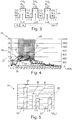
- Figure 3 schematically shows the second volume flow with an oscillating supply of air for carrying out the second combustion stage, which is arranged downstream of the first combustion stage in the direction of movement of the exhaust gas.
- the second reaction gas is fed to the first volume flow such as exhaust gas from the first combustion stage by means of the second supply device in a pulsating manner over time t.
- the mixing of the components is of little or no importance here. Rather, the first combustion stage is operated sub-stoichiometrically with oxygen, i.e. with a combustion air ratio ⁇ ⁇ 1, so that in the second combustion stage, due to the pulsating operation of the second reaction gas, no or less oxygen in first time periods ⁇ t 1 and more oxygen in alternating second time periods ⁇ t 2 is introduced to the first volume flow.
- first time periods ⁇ t 1 for example, components that are not completely oxidized, such as carbon monoxide (CO) and nitrogen compounds, such as ammonia (NH 3 ) and nitrogen oxides (NO x ), remain in the first volume flow from the first combustion stage, such as primary firing. If sufficient air or oxygen is added to the exhaust gas from the primary combustion in the second time periods ⁇ t 2 , so that the combustion air number ⁇ > 1 results, carbon monoxide becomes carbon dioxide (CO 2 ) and the nitrogen oxides with the ammonia in oxygen (O 2 ) and water ( H 2 O) implemented. If continuous operation with a combustion air ratio ⁇ > 1 is known, the nitrogen oxides are further oxidized and cannot be reduced.
- CO carbon monoxide
- nitrogen compounds such as ammonia (NH 3 ) and nitrogen oxides (NO x .
- the time segments .DELTA.t 1 and .DELTA.t 2 can be of different lengths, and the height of the amplitude .DELTA.A can vary.
- the residence time of the mixture of exhaust gas and second reaction gas can thus be set both over the time length of the time segments ⁇ t 1 , ⁇ t 2 , the amplitude ⁇ A and through the frequency, that is to say the repetition rate of the time segments ⁇ t 1 , ⁇ t 2 .
- the carbon monoxide content is used to control the oscillation frequency.
- a currently valid half-hourly mean value of 100 mg / Nm 3 for waste incineration plants or preferably about 50% of the limit value, that is to say less than 50 mg / Nm 3 CO, can be regulated become.
- the oscillation frequency is preferably adjusted so that a carbon monoxide content of less than 50 mg / Nm 3 is achieved and the nitrogen oxide content is reduced.
- FIG. 16 shows diagram 26 of one in the firing system 1a of FIG Figure 2 carried out model combustion process with different parameters over time t.
- Curve 27 shows the course of the volume flow of the first reaction gas - here air.
- Curve 28 shows the course of the second volume flow of the second reaction gas - here air.
- Curve 29 shows the curve of the oxygen content, curve 30 the curve of the carbon dioxide content, curve 31 the curve of the carbon monoxide content and curve 32 the curve of the nitrogen oxide content in each case at the measuring point 20a ( Figure 2 ).
- Curve 33 shows the course of the degree of nitrogen conversion from nitrogen oxide to nitrogen.
- the volume flow of the second reaction gas is operated in a pulsating manner.
- the oxygen content of the pulse minima decreases due to the system.
- the degree of nitrogen conversion increases.
- the nitrogen oxide content in the exhaust gas decreases significantly while the carbon monoxide content is low at the same time.
- the Figure 5 shows the diagram 34 with the bars 35, 36, 37 for the carbon monoxide content and with the bars 38, 39, 40 for the nitrogen oxide content over different oscillation frequencies f.
- a sufficient reduction in the carbon monoxide contents for example of approximately 10 mg / Nm 3 CO based on 11 volume percent oxygen, is possible.
- the nitrogen oxide levels remain at a high level of, for example, about 600 mg / Nm 3 NO x based on 11 volume percent oxygen.
Landscapes
- Engineering & Computer Science (AREA)
- Chemical & Material Sciences (AREA)
- Combustion & Propulsion (AREA)
- Mechanical Engineering (AREA)
- General Engineering & Computer Science (AREA)
Claims (15)
- Système de combustion (1, 1a) pour la combustion d'un combustible solide (5, 5a) amené sur un lit de combustible (6, 6a), comportant un étage de combustion primaire (7, 7a) avec un premier dispositif d'amenée (9) pour l'amenée d'un premier gaz de réaction (8) contenant de l'oxygène et pour la réalisation d'un processus de combustion incomplet avec génération d'un premier débit volumétrique et comportant un étage de combustion secondaire (12, 12a) en aval du premier étage de combustion (7, 7a), avec un deuxième débit volumétrique d'un deuxième gaz de réaction (14) contenant de l'oxygène, amené par un deuxième dispositif d'amenée (13) dans une chambre de gaz d'échappement au-dessus du lit de combustible (6, 6a), dans lequel un mélange de composants des débits volumétriques, qui est modifié de manière stœchiométrique dans le temps, est prévu au moyen du deuxième dispositif d'amenée (13) par le fait que le deuxième dispositif d'amenée (13) est commandé de manière pulsée dans le temps au moyen d'une commande, caractérisé en ce que la commande est configurée pour augmenter et diminuer le deuxième débit volumétrique du deuxième gaz de réaction (14) dans des intervalles de temps (Δt1, Δt2) alternés, de telle sorte qu'une fréquence d'oscillation (f) du deuxième débit volumétrique est commandée en fonction de la teneur en monoxyde de carbone du gaz d'échappement.
- Système de combustion (1, 1a) selon la revendication 1, caractérisé en ce que le débit volumétrique est réglable de manière oscillante.
- Système de combustion (1, 1a) selon la revendication 2, caractérisé en ce que le débit volumétrique est réglable par intermittence.
- Système de combustion (1, la) selon la revendication 2 ou 3, caractérisé en ce que le deuxième dispositif d'amenée (13) est muni d'une soupape à écrasement ou d'une soupape rotative cadencée dans le temps.
- Système de combustion (1, la) selon l'une des revendications 1 à 4, caractérisé en ce qu'au moins l'un des deux débits volumétriques contient de l'ammoniac et/ou de la vapeur d'eau.
- Procédé pour faire fonctionner un système de combustion (1, 1a) pour la combustion d'un combustible solide (5, 5a) amené sur un lit de combustible (6, 6a), comportant un premier étage de combustion (7, 7a) avec un premier dispositif d'amenée (9) pour l'amenée d'un premier gaz de réaction (8) contenant de l'oxygène et comportant un deuxième étage de combustion (12, 12a) avec un deuxième dispositif d'amenée (13) pour une amenée d'un deuxième gaz de réaction (14) contenant de l'oxygène dans une chambre de gaz d'échappement en aval du premier étage de combustion (7, 7a), dans lequel le combustible (5, 5a) est oxydé dans le premier étage de combustion (7, 7a), dans des conditions sous-stœchiométriques, de manière à obtenir un premier débit volumétrique et, par l'amenée d'un deuxième débit volumétrique, variant périodiquement, du deuxième gaz de réaction (14), une postcombustion de gaz dechappement du premier étage de combustion (7, 7a) est réalisée en alternance dans le temps dans des conditions de réaction sous-stœchiométriques et sur-stœchiométriques, caractérisé en ce que dans des intervalles de temps (Δt1, Δt2) alternés, le deuxième débit volumétrique du deuxième gaz de réaction (14) est augmenté et diminué, de telle sorte qu'une fréquence d'oscillation (f) du deuxième débit volumétrique est commandéeen fonction d'une teneur de monoxyde de carbone du gaz d'échappement.
- Procédé selon la revendication 6, caractérisé en ce que les intervalles de temps (Δt2) d'une augmentation du deuxième débit volumétrique sont égaux aux intervalles de temps (Δt1) d'une diminution du deuxième débit volumétrique.
- Procédé selon la revendication 6, caractérisé en ce que les intervalles de temps (Δt2) d'une augmentation du deuxième débit volumétrique sont inégaux par rapport aux intervalles de temps (Δt1) d'une diminution du deuxième débit volumétrique.
- Procédé selon l'une des revendications 6 à 8, caractérisé en ce que le deuxième débit volumétrique est modifié en fonction du temps en forme de rectangle ou en forme de dents de scie.
- Procédé selon l'une des revendications 6 à 9, caractérisé en ce que la fréquence est ajustée à une teneur en monoxyde de carbone inférieure à 100 mg/Nm3.
- Procédé selon la revendication 10, caractérisé en ce que la fréquence est ajustée à une teneur en monoxyde de carbone inférieure à 50 mg/Nm3.
- Procédé selon l'une quelconque des revendications 6 à 11, caractérisé en ce que la combustion incomplète du combustible (5, 5a) est régulée à une teneur résiduelle en ammoniac dans le premier débit volumétrique et/ou de l'ammoniac est ajouté au deuxième débit volumétrique.
- Procédé selon l'une des revendications 6 à 12, caractérisé en ce que de la vapeur d'eau est ajoutée au deuxième gaz de réaction (14).
- Procédé selon l'une des revendications 6 à 13, caractérisé en ce que des portions du premier débit volumétrique sont ajoutées au deuxième débit volumétrique.
- Procédé selon l'une des revendications 6 à 14, caractérisé en ce que le premier gaz de réaction (8) est exploité en modulation.
Applications Claiming Priority (2)
| Application Number | Priority Date | Filing Date | Title |
|---|---|---|---|
| DE102015117718.8A DE102015117718A1 (de) | 2015-10-19 | 2015-10-19 | Feuerungssystem und Verfahren zu dessen Betrieb |
| PCT/DE2016/100485 WO2017067540A1 (fr) | 2015-10-19 | 2016-10-19 | Système de chauffage et procédé de fonctionnement associé |
Publications (2)
| Publication Number | Publication Date |
|---|---|
| EP3365603A1 EP3365603A1 (fr) | 2018-08-29 |
| EP3365603B1 true EP3365603B1 (fr) | 2020-07-22 |
Family
ID=57345622
Family Applications (1)
| Application Number | Title | Priority Date | Filing Date |
|---|---|---|---|
| EP16797719.8A Active EP3365603B1 (fr) | 2015-10-19 | 2016-10-19 | Système de combustion et procédé de fonctionnement associé |
Country Status (3)
| Country | Link |
|---|---|
| EP (1) | EP3365603B1 (fr) |
| DE (1) | DE102015117718A1 (fr) |
| WO (1) | WO2017067540A1 (fr) |
Family Cites Families (9)
| Publication number | Priority date | Publication date | Assignee | Title |
|---|---|---|---|---|
| GB402934A (en) * | 1932-12-01 | 1933-12-14 | Kai Petersen | New or improved method of and apparatus for admitting secondary combustion air into the combustion chambers of furnaces |
| DE3712039A1 (de) * | 1987-04-09 | 1988-10-27 | Muellverbrennungsanlage Wupper | Verbrennungskessel, insbesondere zur muellverbrennung |
| DE4301082C2 (de) * | 1993-01-16 | 1997-11-27 | Steinmueller Gmbh L & C | Verfahren zur Zuführung eines O¶2¶-haltigen Verbrennungsgases zur Verbrennung von stückigem Brenngut in einem Feuerraum mit zugeordnetem Feuerungsrost einer Verbrennungsanlage und Vorrichtung zur Durchführung des Verfahrens |
| DE4313102A1 (de) * | 1993-04-22 | 1994-10-27 | Sbw Sonderabfallentsorgung Bad | Verfahren zum Reduzieren der Abgasmengen zur Eliminierung von NO¶x¶-Emissionen bei der Verbrennung, vorzugsweise bei der Abfallverbrennung |
| FR2837913B1 (fr) * | 2002-03-29 | 2004-11-19 | Air Liquide | Procede de dopage a l'oxygene utilisant la combustion pulsee |
| ES2275086T3 (es) * | 2002-04-03 | 2007-06-01 | Keppel Seghers Holdings Pte Ltd | Metodo y dispositivo para controlar la inyeccion de aire primario y secundario en un sistema de incineracion. |
| DE10347340A1 (de) | 2003-10-11 | 2005-05-19 | Forschungszentrum Karlsruhe Gmbh | Vorrichtung und Verfahren zur Optimierung des Abgasausbrandes in Verbrennungsanlagen |
| DE102006005464B3 (de) * | 2006-02-07 | 2007-07-05 | Forschungszentrum Karlsruhe Gmbh | Verfahren zur primärseitigen Stickoxidminderung in einem zweistufigen Verbrennungsprozess |
| DE102011002205A1 (de) * | 2011-04-20 | 2012-10-25 | Alstom Technology Ltd. | Abhitze-Dampferzeuger sowie ein Verfahren zum Betreiben eines Abhitze-Dampferzeugers |
-
2015
- 2015-10-19 DE DE102015117718.8A patent/DE102015117718A1/de not_active Ceased
-
2016
- 2016-10-19 WO PCT/DE2016/100485 patent/WO2017067540A1/fr not_active Ceased
- 2016-10-19 EP EP16797719.8A patent/EP3365603B1/fr active Active
Non-Patent Citations (1)
| Title |
|---|
| None * |
Also Published As
| Publication number | Publication date |
|---|---|
| EP3365603A1 (fr) | 2018-08-29 |
| DE102015117718A1 (de) | 2017-04-20 |
| WO2017067540A1 (fr) | 2017-04-27 |
Similar Documents
| Publication | Publication Date | Title |
|---|---|---|
| EP1982112B1 (fr) | Procede de reduction primaire d'oxyde d'azote dans un procede de combustion en deux etapes | |
| DE69210381T2 (de) | Verfahren zur Verminderung des Ausstosses bei der Verbrennung von stickstoffhaltigen Brennstoffen | |
| DE69806182T2 (de) | Klinkerproduktionskontrolle durch analyse des schwefelgehalts im endprodukt | |
| DE69515667T2 (de) | Verbrennungsverfahren | |
| EP1698827B1 (fr) | Procédé pour brûler des combustibles et plus particulièrement des déchets | |
| DE69420051T2 (de) | System mit niedrigem ausstoss und mit niedrigem luftüberschuss | |
| DE69111058T2 (de) | Verfahren zur Verminderung des Ausstosses von Distickstoffoxid bei der Verbrennung von stickstoffhaltigem Brennstoff in Wirbelschichtreaktoren. | |
| DE3331989A1 (de) | Verfahren zur verminderung der no(pfeil abwaerts)x(pfeil abwaerts)-emission bei der verbrennung von stickstoffhaltigen brennstoffen | |
| DE3915992A1 (de) | Verfahren zur reduktion von stickstoffoxiden | |
| EP1281026B1 (fr) | Procede et dispositif pour incinerer des sous-produits organiques | |
| WO1986006151A1 (fr) | Procede et installation d'incineration de dechets | |
| EP0132584A2 (fr) | Procédé et installation pour diminuer l'émission de la matière nocive dans les gaz d'échappement des installations de combustion | |
| DE69614379T2 (de) | NOx-Verminderung in einem Dampferzeuger mit zirkulierender Wirbelschicht | |
| EP3365603B1 (fr) | Système de combustion et procédé de fonctionnement associé | |
| EP0898688B1 (fr) | PROCEDE POUR REDUIRE AU MINIMUM LA TENEUR EN NOx DES GAZ DE FUMEE | |
| DD290042A5 (de) | Verbrennungsverfahren zum einschraenken einer bildung von stickstoffoxiden bei verbrennung und anordnung zum ausfuehren des verfahrens | |
| EP2691701A1 (fr) | Procédé d'optimisation de la combustion totale des gaz d'échappement d'une installation de combustion | |
| DE69309636T2 (de) | Vorrichtung und Verfahren für thermische Zerstörung von sauren Substanzen in Rauchgasen | |
| EP1077077A2 (fr) | Procédé de traitement thermique de matières solides | |
| DE60022298T2 (de) | Verfahren und Vorrichtung zur Verbesserung der Verbrennung in einer zirkulierenden Wirbelschichtanlage | |
| DE102009019118A1 (de) | Hausfeuerungsanlage mit kontinuierlicher Feststoffverbrennung und Verfahren zu deren Betrieb | |
| DE3009366A1 (de) | Einrichtung zur trocknen entfernung von schadstoffen aus rauchgasen | |
| CH673149A5 (fr) | ||
| EP1918015A1 (fr) | Equilibrage des gaz de fumées dans des installations de combustion de déchets | |
| EP0363812A2 (fr) | Procédé et installation pour la génération de vapeur dans une centrale de cogénération de puissance et de chaleur |
Legal Events
| Date | Code | Title | Description |
|---|---|---|---|
| STAA | Information on the status of an ep patent application or granted ep patent |
Free format text: STATUS: UNKNOWN |
|
| STAA | Information on the status of an ep patent application or granted ep patent |
Free format text: STATUS: THE INTERNATIONAL PUBLICATION HAS BEEN MADE |
|
| PUAI | Public reference made under article 153(3) epc to a published international application that has entered the european phase |
Free format text: ORIGINAL CODE: 0009012 |
|
| STAA | Information on the status of an ep patent application or granted ep patent |
Free format text: STATUS: REQUEST FOR EXAMINATION WAS MADE |
|
| 17P | Request for examination filed |
Effective date: 20180329 |
|
| AK | Designated contracting states |
Kind code of ref document: A1 Designated state(s): AL AT BE BG CH CY CZ DE DK EE ES FI FR GB GR HR HU IE IS IT LI LT LU LV MC MK MT NL NO PL PT RO RS SE SI SK SM TR |
|
| AX | Request for extension of the european patent |
Extension state: BA ME |
|
| DAV | Request for validation of the european patent (deleted) | ||
| DAX | Request for extension of the european patent (deleted) | ||
| GRAP | Despatch of communication of intention to grant a patent |
Free format text: ORIGINAL CODE: EPIDOSNIGR1 |
|
| STAA | Information on the status of an ep patent application or granted ep patent |
Free format text: STATUS: GRANT OF PATENT IS INTENDED |
|
| INTG | Intention to grant announced |
Effective date: 20191209 |
|
| GRAS | Grant fee paid |
Free format text: ORIGINAL CODE: EPIDOSNIGR3 |
|
| GRAJ | Information related to disapproval of communication of intention to grant by the applicant or resumption of examination proceedings by the epo deleted |
Free format text: ORIGINAL CODE: EPIDOSDIGR1 |
|
| GRAL | Information related to payment of fee for publishing/printing deleted |
Free format text: ORIGINAL CODE: EPIDOSDIGR3 |
|
| STAA | Information on the status of an ep patent application or granted ep patent |
Free format text: STATUS: REQUEST FOR EXAMINATION WAS MADE |
|
| GRAP | Despatch of communication of intention to grant a patent |
Free format text: ORIGINAL CODE: EPIDOSNIGR1 |
|
| STAA | Information on the status of an ep patent application or granted ep patent |
Free format text: STATUS: GRANT OF PATENT IS INTENDED |
|
| INTC | Intention to grant announced (deleted) | ||
| INTG | Intention to grant announced |
Effective date: 20200507 |
|
| GRAA | (expected) grant |
Free format text: ORIGINAL CODE: 0009210 |
|
| STAA | Information on the status of an ep patent application or granted ep patent |
Free format text: STATUS: THE PATENT HAS BEEN GRANTED |
|
| AK | Designated contracting states |
Kind code of ref document: B1 Designated state(s): AL AT BE BG CH CY CZ DE DK EE ES FI FR GB GR HR HU IE IS IT LI LT LU LV MC MK MT NL NO PL PT RO RS SE SI SK SM TR |
|
| REG | Reference to a national code |
Ref country code: GB Ref legal event code: FG4D Free format text: NOT ENGLISH |
|
| REG | Reference to a national code |
Ref country code: CH Ref legal event code: EP |
|
| REG | Reference to a national code |
Ref country code: DE Ref legal event code: R096 Ref document number: 502016010606 Country of ref document: DE |
|
| REG | Reference to a national code |
Ref country code: AT Ref legal event code: REF Ref document number: 1293740 Country of ref document: AT Kind code of ref document: T Effective date: 20200815 |
|
| REG | Reference to a national code |
Ref country code: IE Ref legal event code: FG4D Free format text: LANGUAGE OF EP DOCUMENT: GERMAN |
|
| REG | Reference to a national code |
Ref country code: LT Ref legal event code: MG4D |
|
| PG25 | Lapsed in a contracting state [announced via postgrant information from national office to epo] |
Ref country code: FI Free format text: LAPSE BECAUSE OF FAILURE TO SUBMIT A TRANSLATION OF THE DESCRIPTION OR TO PAY THE FEE WITHIN THE PRESCRIBED TIME-LIMIT Effective date: 20200722 Ref country code: GR Free format text: LAPSE BECAUSE OF FAILURE TO SUBMIT A TRANSLATION OF THE DESCRIPTION OR TO PAY THE FEE WITHIN THE PRESCRIBED TIME-LIMIT Effective date: 20201023 Ref country code: NO Free format text: LAPSE BECAUSE OF FAILURE TO SUBMIT A TRANSLATION OF THE DESCRIPTION OR TO PAY THE FEE WITHIN THE PRESCRIBED TIME-LIMIT Effective date: 20201022 Ref country code: SE Free format text: LAPSE BECAUSE OF FAILURE TO SUBMIT A TRANSLATION OF THE DESCRIPTION OR TO PAY THE FEE WITHIN THE PRESCRIBED TIME-LIMIT Effective date: 20200722 Ref country code: HR Free format text: LAPSE BECAUSE OF FAILURE TO SUBMIT A TRANSLATION OF THE DESCRIPTION OR TO PAY THE FEE WITHIN THE PRESCRIBED TIME-LIMIT Effective date: 20200722 Ref country code: PT Free format text: LAPSE BECAUSE OF FAILURE TO SUBMIT A TRANSLATION OF THE DESCRIPTION OR TO PAY THE FEE WITHIN THE PRESCRIBED TIME-LIMIT Effective date: 20201123 Ref country code: BG Free format text: LAPSE BECAUSE OF FAILURE TO SUBMIT A TRANSLATION OF THE DESCRIPTION OR TO PAY THE FEE WITHIN THE PRESCRIBED TIME-LIMIT Effective date: 20201022 Ref country code: LT Free format text: LAPSE BECAUSE OF FAILURE TO SUBMIT A TRANSLATION OF THE DESCRIPTION OR TO PAY THE FEE WITHIN THE PRESCRIBED TIME-LIMIT Effective date: 20200722 Ref country code: ES Free format text: LAPSE BECAUSE OF FAILURE TO SUBMIT A TRANSLATION OF THE DESCRIPTION OR TO PAY THE FEE WITHIN THE PRESCRIBED TIME-LIMIT Effective date: 20200722 |
|
| PG25 | Lapsed in a contracting state [announced via postgrant information from national office to epo] |
Ref country code: LV Free format text: LAPSE BECAUSE OF FAILURE TO SUBMIT A TRANSLATION OF THE DESCRIPTION OR TO PAY THE FEE WITHIN THE PRESCRIBED TIME-LIMIT Effective date: 20200722 Ref country code: PL Free format text: LAPSE BECAUSE OF FAILURE TO SUBMIT A TRANSLATION OF THE DESCRIPTION OR TO PAY THE FEE WITHIN THE PRESCRIBED TIME-LIMIT Effective date: 20200722 Ref country code: RS Free format text: LAPSE BECAUSE OF FAILURE TO SUBMIT A TRANSLATION OF THE DESCRIPTION OR TO PAY THE FEE WITHIN THE PRESCRIBED TIME-LIMIT Effective date: 20200722 Ref country code: IS Free format text: LAPSE BECAUSE OF FAILURE TO SUBMIT A TRANSLATION OF THE DESCRIPTION OR TO PAY THE FEE WITHIN THE PRESCRIBED TIME-LIMIT Effective date: 20201122 |
|
| PG25 | Lapsed in a contracting state [announced via postgrant information from national office to epo] |
Ref country code: NL Free format text: LAPSE BECAUSE OF FAILURE TO SUBMIT A TRANSLATION OF THE DESCRIPTION OR TO PAY THE FEE WITHIN THE PRESCRIBED TIME-LIMIT Effective date: 20200722 |
|
| REG | Reference to a national code |
Ref country code: DE Ref legal event code: R097 Ref document number: 502016010606 Country of ref document: DE |
|
| PG25 | Lapsed in a contracting state [announced via postgrant information from national office to epo] |
Ref country code: SM Free format text: LAPSE BECAUSE OF FAILURE TO SUBMIT A TRANSLATION OF THE DESCRIPTION OR TO PAY THE FEE WITHIN THE PRESCRIBED TIME-LIMIT Effective date: 20200722 Ref country code: EE Free format text: LAPSE BECAUSE OF FAILURE TO SUBMIT A TRANSLATION OF THE DESCRIPTION OR TO PAY THE FEE WITHIN THE PRESCRIBED TIME-LIMIT Effective date: 20200722 Ref country code: IT Free format text: LAPSE BECAUSE OF FAILURE TO SUBMIT A TRANSLATION OF THE DESCRIPTION OR TO PAY THE FEE WITHIN THE PRESCRIBED TIME-LIMIT Effective date: 20200722 Ref country code: RO Free format text: LAPSE BECAUSE OF FAILURE TO SUBMIT A TRANSLATION OF THE DESCRIPTION OR TO PAY THE FEE WITHIN THE PRESCRIBED TIME-LIMIT Effective date: 20200722 Ref country code: CZ Free format text: LAPSE BECAUSE OF FAILURE TO SUBMIT A TRANSLATION OF THE DESCRIPTION OR TO PAY THE FEE WITHIN THE PRESCRIBED TIME-LIMIT Effective date: 20200722 Ref country code: DK Free format text: LAPSE BECAUSE OF FAILURE TO SUBMIT A TRANSLATION OF THE DESCRIPTION OR TO PAY THE FEE WITHIN THE PRESCRIBED TIME-LIMIT Effective date: 20200722 |
|
| PLBE | No opposition filed within time limit |
Free format text: ORIGINAL CODE: 0009261 |
|
| STAA | Information on the status of an ep patent application or granted ep patent |
Free format text: STATUS: NO OPPOSITION FILED WITHIN TIME LIMIT |
|
| PG25 | Lapsed in a contracting state [announced via postgrant information from national office to epo] |
Ref country code: AL Free format text: LAPSE BECAUSE OF FAILURE TO SUBMIT A TRANSLATION OF THE DESCRIPTION OR TO PAY THE FEE WITHIN THE PRESCRIBED TIME-LIMIT Effective date: 20200722 |
|
| 26N | No opposition filed |
Effective date: 20210423 |
|
| PG25 | Lapsed in a contracting state [announced via postgrant information from national office to epo] |
Ref country code: SK Free format text: LAPSE BECAUSE OF FAILURE TO SUBMIT A TRANSLATION OF THE DESCRIPTION OR TO PAY THE FEE WITHIN THE PRESCRIBED TIME-LIMIT Effective date: 20200722 Ref country code: MC Free format text: LAPSE BECAUSE OF FAILURE TO SUBMIT A TRANSLATION OF THE DESCRIPTION OR TO PAY THE FEE WITHIN THE PRESCRIBED TIME-LIMIT Effective date: 20200722 Ref country code: LU Free format text: LAPSE BECAUSE OF NON-PAYMENT OF DUE FEES Effective date: 20201019 |
|
| REG | Reference to a national code |
Ref country code: BE Ref legal event code: MM Effective date: 20201031 |
|
| PG25 | Lapsed in a contracting state [announced via postgrant information from national office to epo] |
Ref country code: SI Free format text: LAPSE BECAUSE OF FAILURE TO SUBMIT A TRANSLATION OF THE DESCRIPTION OR TO PAY THE FEE WITHIN THE PRESCRIBED TIME-LIMIT Effective date: 20200722 Ref country code: BE Free format text: LAPSE BECAUSE OF NON-PAYMENT OF DUE FEES Effective date: 20201031 |
|
| REG | Reference to a national code |
Ref country code: NL Ref legal event code: MP Effective date: 20200722 |
|
| PG25 | Lapsed in a contracting state [announced via postgrant information from national office to epo] |
Ref country code: IE Free format text: LAPSE BECAUSE OF NON-PAYMENT OF DUE FEES Effective date: 20201019 |
|
| PG25 | Lapsed in a contracting state [announced via postgrant information from national office to epo] |
Ref country code: TR Free format text: LAPSE BECAUSE OF FAILURE TO SUBMIT A TRANSLATION OF THE DESCRIPTION OR TO PAY THE FEE WITHIN THE PRESCRIBED TIME-LIMIT Effective date: 20200722 Ref country code: MT Free format text: LAPSE BECAUSE OF FAILURE TO SUBMIT A TRANSLATION OF THE DESCRIPTION OR TO PAY THE FEE WITHIN THE PRESCRIBED TIME-LIMIT Effective date: 20200722 Ref country code: CY Free format text: LAPSE BECAUSE OF FAILURE TO SUBMIT A TRANSLATION OF THE DESCRIPTION OR TO PAY THE FEE WITHIN THE PRESCRIBED TIME-LIMIT Effective date: 20200722 |
|
| PG25 | Lapsed in a contracting state [announced via postgrant information from national office to epo] |
Ref country code: MK Free format text: LAPSE BECAUSE OF FAILURE TO SUBMIT A TRANSLATION OF THE DESCRIPTION OR TO PAY THE FEE WITHIN THE PRESCRIBED TIME-LIMIT Effective date: 20200722 |
|
| REG | Reference to a national code |
Ref country code: CH Ref legal event code: U11 Free format text: ST27 STATUS EVENT CODE: U-0-0-U10-U11 (AS PROVIDED BY THE NATIONAL OFFICE) Effective date: 20251101 |
|
| PGFP | Annual fee paid to national office [announced via postgrant information from national office to epo] |
Ref country code: DE Payment date: 20251020 Year of fee payment: 10 |
|
| PGFP | Annual fee paid to national office [announced via postgrant information from national office to epo] |
Ref country code: GB Payment date: 20251024 Year of fee payment: 10 |
|
| PGFP | Annual fee paid to national office [announced via postgrant information from national office to epo] |
Ref country code: AT Payment date: 20251021 Year of fee payment: 10 |
|
| PGFP | Annual fee paid to national office [announced via postgrant information from national office to epo] |
Ref country code: FR Payment date: 20251029 Year of fee payment: 10 |
|
| PGFP | Annual fee paid to national office [announced via postgrant information from national office to epo] |
Ref country code: CH Payment date: 20251101 Year of fee payment: 10 |