EP3366105B1 - Aufsitzmäher - Google Patents
Aufsitzmäher Download PDFInfo
- Publication number
- EP3366105B1 EP3366105B1 EP17204471.1A EP17204471A EP3366105B1 EP 3366105 B1 EP3366105 B1 EP 3366105B1 EP 17204471 A EP17204471 A EP 17204471A EP 3366105 B1 EP3366105 B1 EP 3366105B1
- Authority
- EP
- European Patent Office
- Prior art keywords
- end side
- portions
- protection structure
- rollover protection
- leading end
- Prior art date
- Legal status (The legal status is an assumption and is not a legal conclusion. Google has not performed a legal analysis and makes no representation as to the accuracy of the status listed.)
- Active
Links
Images


Classifications
-
- A—HUMAN NECESSITIES
- A01—AGRICULTURE; FORESTRY; ANIMAL HUSBANDRY; HUNTING; TRAPPING; FISHING
- A01D—HARVESTING; MOWING
- A01D43/00—Mowers combined with apparatus performing additional operations while mowing
- A01D43/06—Mowers combined with apparatus performing additional operations while mowing with means for collecting, gathering or loading mown material
- A01D43/063—Mowers combined with apparatus performing additional operations while mowing with means for collecting, gathering or loading mown material in or into a container carried by the mower; Containers therefor
- A01D43/0635—Mowers combined with apparatus performing additional operations while mowing with means for collecting, gathering or loading mown material in or into a container carried by the mower; Containers therefor with emptying means
Definitions
- This invention relates to a riding-type mower.
- a riding-type mower noted above includes a traveling vehicle body having a driver's seat, a rollover protection structure, also known as ROPS, mounted at a rear portion of the traveling vehicle body, a mower unit mounted on the traveling vehicle body, and a grass collecting container supported by the traveling vehicle body at a rear portion thereof and configured to store grass clippings cut by the mower unit.
- the grass collecting container is supported by the traveling vehicle body to be switchably and pivotally elevated/lowered between an elevated discharging posture realized when the container is pivotally elevated about a pivot axis disposed at an upper portion of this grass collecting container and extending along a lateral width direction of the traveling vehicle body, and a lowered storing posture realized when the container is pivotally lowered about the pivot axis.
- a grass collecting container is supported by a traveling vehicle body at a rear portion thereof, and a ROPS is mounted between a driver's seat and the grass collecting container.
- the ROPS consists of a pair of right and left base end portions and a portal-shaped frame portion extending continuously from upper ends of the right and left base end portions.
- the portal-shaped frame portion is formed to be collapsible to the rear side about a pivot point and can be switched between an erect posture oriented along the vertical direction and a rearwardly collapsed posture.
- the portal-shaped frame portion when switched to the rearwardly collapsed posture, assumes a posture aligned with an upper face of a container body of the grass collecting container which face is placed in a rearwardly and upwardly sloped state.
- the ROPS includes a pair of right and left base end side ROPS portions protruding upwards from the traveling vehicle body, and a leading end side ROPS portion which is supported to the leading end portions of the pair of right and left base end side ROPS portions to be pivotally raised/collapsed, and is switchable between a use posture in which the leading end side ROPS portion is raised relative to the base end side ROPS portions and a storage posture in which the leading end side ROPS portion is collapsed to the rear side of the traveling vehicle body relative to the base end side ROPS portions. Then, during a work effected near a tree, the leading end side ROPS portion will be set to the storage posture, thus reducing possibility of the ROPS being accidentally hooked with the tree.
- the leading end side ROPS portion when the leading end side ROPS portion is configured to be posture-changeable to the storage posture, the leading end side POPS portion assumes a posture aligned with the upper face of the grass collecting container. Therefore, with the above-described riding-type mower, when the leading end side ROPS posture is set to the storage posture and the grass collecting container is set to the elevated discharging posture, it is necessary to avoid accidental contact between the leading end side ROPS portion and the grass collecting container. For this reason, it is not possible to secure a large lower margin from the use posture of the leading end side ROPS portion when this ROPS posture is set to the storage posture. Namely, it is not possible to lower the leading end side ROPS portion sufficiently even when this leading end side ROPS posture is set to the storage posture.
- EP 2870855 discloses a riding type mower.
- a riding-type mower comprising:
- the arrangement still allows lower positioning of the leading end side ROPS portion when set to the storage posture. For instance, it is possible to effectively avoid accidental contact of the ROPS with a tree by setting the leading end side ROPS portion to the storage posture.
- leading end side ROPS portion is supported to be posture-changeable to a second storage posture in which the leading end side ROPS portion is further pivotally lowered than the storage posture and is located on the rear side of the pair of right and left base end side ROPS portions along the base end side ROPS portions.
- leading end side ROPS portion is located higher than the grass collecting container when the grass collecting container is set to the lowered storage posture and also the leading end side ROPS portion assumes the second storage posture.
- the mower further comprises a pair of right and left brackets that are attached to the traveling vehicle body and that support the pair of right and left base end side ROPS portions detachably/attachablly and independently of each other; and wherein the pair of right and left brackets include a holding portion configured to hold joint portions of the base end side ROPS portions when the joint portions are inserted into the pair of right and left brackets from above.
- a direction [F] is defined to designate a front direction of a traveling vehicle body
- a direction [B] is defined to designate a rear direction of the traveling vehicle body
- a direction on the near side of the illustrations is defined to designate a left side direction of the traveling vehicle body
- a direction on the far side of the illustrations is defined to designate a right side direction of the traveling vehicle body, respectively.
- a riding-type mower includes a traveling vehicle body that mounts a pair of left and front wheels 1 which are steerable and a pair of right and left rear wheels 2 which are drivable.
- an engine section 3 is formed at a front portion of the traveling vehicle body.
- An engine 4 is provided in the engine section 3.
- the traveling vehicle body travels as the rear wheels 2 are driven by power of the engine 4.
- a driving section 5 is formed at a rear portion of the traveling vehicle body.
- the traveling vehicle body is configured as a riding type as a person rides in the driving section 5 and steers the front wheels 1 by a rotational operation of the steering wheel 7.
- a rollover protection structure also known as ROPS 30, is provided at a rear portion of the traveling vehicle body.
- a mower unit 8 is supported at a portion of the traveling vehicle body between the front wheels 1 and the rear wheels 2.
- the mower unit 8 is supported by the traveling vehicle body via a link mechanism 9, so that in response to an elevating/lowering operation of the link mechanism 9, the mower unit 8 is operated up/down between a lowered work state and an elevated non-work state.
- a grass collecting container 10 To a rear portion of the traveling vehicle body, there is supported a grass collecting container 10.
- a duct 11 is provided between the mower unit 8 and the grass collecting container 10. The duct 11 extends between the right and left rear wheels 2.
- a grass cutting operation can be effected.
- a rotary cutter blade 8a is rotatably driven by the power of the engine 4, so that grass is cut by the rotary cutter blade 8a. Cut grass clippings are transported by conveying air current generated with the rotation of the rotary cutter blade 8a through the duct 1 into the grass collecting container 10 to be stored therein.
- a pair of right and left support frames 12 which extend along a vertical direction of the traveling vehicle body.
- the right and left support frames 12 are supported by a vehicle body frame 17 via a first joint frame 13, right/left second joint frames 14, a third joint frame 15 and right/left brackets 16.
- the first joint frame 13 joins lower portions of the right and left support frames 12.
- the third joint frame 15 joins the right and left brackets 16.
- the right/left second joint frame 14 join the first joint frame 13 to the third joint frame 15.
- Each bracket 16 is supported by the vehicle body frame 17 of the traveling vehicle boy via a joint members 16b.
- support portions 18 are formed at right and left corners at the upper portion on the front end side of the grass collecting container 10.
- a support shaft 19 extends between the right and left support portions 18.
- the right and left support portions 18 consist of support members 18a fixed to the corner portions of the grass collecting container 10 and pivot links 18b to whose free ends the support members 18a are coupled, respectively.
- the grass collecting container 10 is supported by the right and left support frames 12 via the support shaft 19 to be vertically pivotable about an axis P that extends along a lateral width direction of the traveling vehicle body.
- a coupling shaft 20 is operably coupled to the right and left pivot links 18b, and in turn the right and left pivot links 18b are operably coupled by the coupling shaft 20 to be pivotable together about the axis P acting as the pivot.
- Right and left lift cylinders 21 are operably coupled to the coupling shaft 20.
- the pivot links 18b are pivoted up/down about the axis P by the lift cylinder 21, whereby the grass collecting container 10 is pivoted up/down together with the pivot links 18b.
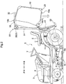
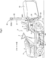
- the grass collecting container 10 can be switched over in its posture between an elevated discharging posture (see Fig. 2 ) and a lowered storing posture (see Fig. 1 ).
- the support members 18a and the pivot links 18b are connected to each other via connecting bolts. When the connection between the support members 18a and the pivot links 18b is released, the grass collecting container 10 can be detached from the support frames 12.
- the lift cylinder 21 will be operated in advance to the storage side to set the grass collecting container 10 to the lowered storing posture.
- the collector 10 will assume a mounted posture with its opening 10a facing forwardly of the vehicle body to face an exit of the duct 11, so that grass clippings cut by the mower unit 8 can be collected in the grass collecting container 10 to be stored therein.
- a hook 22 is supported at a lower portion of the support frame 12 to be pivotally operable.
- the lift cylinder 21 will be operated to the discharging side to set the grass collecting container 10 to an elevated discharging posture. Then, the rear side of the grass collecting container 10 will be elevated to assume a mounted posture with its opening 18b being oriented downwards. Then, the glass clippings inside the grass collecting container 10 will be allowed to drop under gravity to be discharged through the opening 10a.
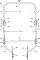
- the ROPS 30 includes a pair of right and left base end side ROPS portions 31 and one leading end side ROPS portion 32.
- a pair of right and left brackets 16 are supported via the joint members 16b by the right and left vehicle body frames 17 at the rear portions thereof.
- the brackets 16 are located more rearward than the rear wheels 2.
- the lower end portions of the right and left base end side ROPS portions 31 are supported by the brackets 16 at respective extension end portions thereof.
- the right and left base end side ROPS portions 31 are supported by the vehicle body frames 17 via the brackets 16, respectively, under a vertically oriented posture extending along the vertical direction of the traveling vehicle body.
- each joint portion 31a is formed at the base end portion of the base end side ROPS portion 31.
- a vertically oriented tubular holding portion 16a extending along the vertical direction of the traveling vehicle body.
- the leading end side ROPS portion 32 includes a pair of right and left strut portions 33, and a beam portion 34 connected to leading ends of the pair of right and left strut portions 33.
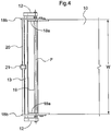
- the leading end side ROPS portion 32 as a whole is configured in U-shape, with a distance between the pair of right and left strut portions 33 being greater than a lateral width W of the grass collecting container 10 (see Fig. 4 ).
- right and left joint portions 33a are formed at respective lower ends of the right and left strut portions 33.
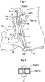
- Right and left support portions 31b are formed at respective upper ends of the right and left base end side ROPS portions 31. Between the right and left support portions 31b, the joint portions 33a are supported by the right and left support portions 31b via support shafts 35, respectively.
- the leading end side ROPS portion 32 is supported by the right and left support portions 31b at opposite ends thereof via the support shafts 35, to be pivotably operable about an axis X of the respective support shaft 35 extending in the lateral width direction of the traveling vehicle body.
- each joint portion 33a defines two lock holes 36.
- each support portion 31b defines four positioning holes 37.
- the leading end side ROPS portion 32 in response to a pivotal operation on the leading end side ROPS portion 32, when the two lock holes 36 are put into registry with a first positioning hole 37a and a second positioning hole 37b of the four positioning holes 37, the leading end side ROPS portion 32 will be raised relative to the base end side ROPS portions 31, thus assuming a use posture.
- a detachable lock pin 38 will be fitted to/between the first positioning hole 37a and one lock hole 36, and another detachable lock pin 38 will be fitted to/between the second positioning hole 37b and the other lock hole 36.
- the leading end side ROPS portion 32 can be locked under the use posture.
- a detachable lock pin 38 will be fitted to/between the second positioning hole 37b and one lock hole 36, and another detachable lock pin 38 will be fitted to/between the third positioning hole 37c and the other lock hole 36.
- the leading end side ROPS portion 32 can be locked under the first storage posture.
- the leading end side ROPS portion 32 is set to the first storage posture and the grass collecting container 10 is set to the elevated discharging posture, a free end portion 10b of the grass collecting container 10 enters the space between the right and left strut portions 33 and also the free end side portion 10b of the grass collecting container 10 will protrude upwards beyond the right and left strut portions 33.
- the leading end side ROPS portion 32 in response to a pivotal operation on the leading end side ROPS portion 32, when the two lock holes 36 are put into registry with the third positioning hole 37c and a fourth positioning hole 37d of the four positioning holes 37, the leading end side ROPS portion 32 will be positioned along the base end side ROPS portions 31 on the rear side of the base end side ROPS portion 31, thus assuming a second storage posture which is more lowered than the first storage posture.
- a detachable lock pin 38 will be fitted to/between the third positioning hole 37c and one lock hole 36, and another detachable lock pin 38 will be fitted to/between the fourth positioning hole 37d and the other lock hole 36.
- the leading end side ROPS portion 32 can be locked under the second storage posture.
- the leading end side ROPS portion 32 When the leading end side ROPS portion 32 is set to the second storage posture and the grass collecting container 10 is set to the lowered storage posture, the leading end side ROPS portion 32 will be located more upwards than the grass collecting container 10.
- the height of the ROPS 30 can be reduced, so that it becomes possible to carry out the cutting/mowing operation with readily avoiding accidental hooking of the tree with the ROPS 30.
- the free end side portion 10b of the grass collecting container 10 enters the space between the right and left strut portions 33 to prevent the grass collecting container 10 from coming into contact with the leading end side ROPS portion 32. Consequently, with setting the grass collecting container 10 to the elevated discharging posture, grass clippings can be discharged from this grass collecting container 10.
- a grass cutting operation can be carried out with securing a large empty space above the grass collecting container 10 assuming the lowed storage posture.
- the grass collecting container 10 can be elevated to its elevated discharging posture to allow the discharging.
Landscapes
- Life Sciences & Earth Sciences (AREA)
- Environmental Sciences (AREA)
- Harvester Elements (AREA)
Claims (4)
- Aufsitzmäher, umfassend:eine fahrende Fahrzeugkarosserie mit einem Fahrersitz (6),eine Überrollschutzstruktur (30), die an einem hinteren Abschnitt der fahrenden Fahrzeugkarosserie montiert ist,eine Mäheinheit (8), die an der fahrenden Fahrzeugkarosserie montiert ist,einen Grassammelbehälter (10), der von der fahrenden Fahrzeugkarosserie an einem hinteren Abschnitt davon getragen wird und dazu ausgestaltet ist, Grasabfälle zu lagern, die von der Mäheinheit (8) geschnitten werden,wobei der Grassammelbehälter (10) von der fahrenden Fahrzeugkarosserie getragen wird, um umschaltbar und schwenkbar zwischen einer angehobenen Abladestellung, die realisiert wird, wenn der Behälter (10) schwenkbar um eine Schwenkachse (P) angehoben wird, die oberhalb des Grassammelbehälters angeordnet ist und sich entlang einer seitlichen Breitenrichtung der fahrenden Fahrzeugkarosserie erstreckt, und einer abgesenkten Lagerungsstellung, die realisiert wird, wenn der Behälter (10) schwenkbar um die Schwenkachse (P) abgesenkt wird, angehoben/abgesenkt zu werden, unddie Überrollschutzstruktur (30) ein Paar von rechten und linken Basisendseiten-Überrollschutzstrukturabschnitten (31), die nach oben von der fahrenden Fahrzeugkarosserie vorstehen, und einen Vorderendseiten-Überrollschutzstrukturabschnitt (32) beinhaltet, der an den Vorderendabschnitten des Paares von rechten und linken Basisendseiten-Überrollschutzstrukturabschnitten (31) abgestützt ist, um schwenkbar erhöht/zusammengefaltet zu werden, und zwischen einer Benutzungsstellung, in welcher der Vorderendseiten-Überrollschutzstrukturabschnitt relativ zu den Basisendseiten-Überrollschutzstrukturabschnitten (31) erhöht ist, und einer Lagerungsstellung, in welcher der Vorderendseiten-Überrollschutzstrukturabschnitt (32) zu der hinteren Seite der fahrenden Fahrzeugkarosserie relativ zu den Basisendseiten-Überrollschutzstrukturabschnitten (31) zusammengefaltet ist, umschaltbar ist,wobei der Vorderendseiten-Überrollschutzstrukturabschnitt (32) ein Paar von rechten und linken Strebenabschnitten (33), die Basisendabschnitte aufweisen, die an den Vorderendabschnitten des Paares von rechten und linken Basisendseiten-Überrollschutzstrukturabschnitten (31) abgestützt sind, und einen Trägerabschnitt (34), der mit Vorderenden des Paares von rechten und linken Strebenabschnitten (33) verbunden ist, beinhaltet,dadurch gekennzeichnet, dass ein Abstand (D) zwischen dem Paar von rechten und linken Strebenabschnitten (33) größer ist als eine seitliche Breite (W) des Grassammelbehälters (10), undwobei eine freie Endseite des Grassammelbehälters (10) in einen Raum zwischen dem Paar von echten und linken Strebenabschnitten (33) eintritt, wenn der Vorderendseiten-Überrollschutzstrukturabschnitt (32) die Lagerungsstellung einnimmt und auch der Grassammelbehälter (10) die angehobene Abladestellung einnimmt.
- Aufsitzmäher nach Anspruch 1, wobei der Vorderendseiten-Überrollschutzstrukturabschnitt (32) dazu abgestützt ist, zu einer zweiten Lagerungsstellung stellungsänderbar zu sein, in welcher der Vorderendseiten-Überrollchutzstrukturabschnitt (32) weiter schwenkbar als die Lagerungsstellung abgesenkt wird und sich an der hinteren Seite des Paares von rechten und linken Basisendseiten-Überrollschutzstrukturabschnitten (31) entlang der Basisendseiten-Überrollschutzstrukturabschnitte (31) befindet.
- Aufsitzmäher nach Anspruch 2, wobei sich der Vorderendseiten-Überrollschutzstrukturabschnitt (32) höher als der Grassammelbehälter (10) befindet, wenn der Grassammelbehälter (10) auf die untere Lagerungsstellung gesetzt ist und auch der Vorderendseiten-Überrollschutzstrukturabschnitt (32) die zweite Lagerungsstellung einnimmt.
- Aufsitzmäher nach einem der vorhergehenden Ansprüche, wobei:
der Mäher ferner ein Paar von rechten und linken Halterungen (16) umfasst, die an der fahrenden Fahrzeugkarosserie angebracht sind und die das Paar von rechten und linken Basisendseiten-Überrollschutzstrukturabschnitten (31) abnehmbar/anbringbar und unabhängig voneinander tragen, und
wobei das Paar von rechten und linken Halterungen (16) einen Halteabschnitt (16a) umfasst, der dazu ausgestaltet ist, Verbindungsabschnitte (31a) der Basisendseiten-Überrollschutzstrukturabschnitte (31) zu halten, wenn die Verbindungsabschnitte (31a) in das Paar von rechten und linken Halterungen von oben eingesetzt werden.
Applications Claiming Priority (1)
| Application Number | Priority Date | Filing Date | Title |
|---|---|---|---|
| JP2017032214A JP6815223B2 (ja) | 2017-02-23 | 2017-02-23 | 乗用型草刈機 |
Publications (2)
| Publication Number | Publication Date |
|---|---|
| EP3366105A1 EP3366105A1 (de) | 2018-08-29 |
| EP3366105B1 true EP3366105B1 (de) | 2020-03-04 |
Family
ID=60515233
Family Applications (1)
| Application Number | Title | Priority Date | Filing Date |
|---|---|---|---|
| EP17204471.1A Active EP3366105B1 (de) | 2017-02-23 | 2017-11-29 | Aufsitzmäher |
Country Status (2)
| Country | Link |
|---|---|
| EP (1) | EP3366105B1 (de) |
| JP (1) | JP6815223B2 (de) |
Families Citing this family (1)
| Publication number | Priority date | Publication date | Assignee | Title |
|---|---|---|---|---|
| JP7239748B2 (ja) * | 2018-10-10 | 2023-03-14 | 株式会社クボタ | 乗用型草刈機 |
Family Cites Families (11)
| Publication number | Priority date | Publication date | Assignee | Title |
|---|---|---|---|---|
| JP3289327B2 (ja) * | 1992-07-31 | 2002-06-04 | 井関農機株式会社 | トラクターの安全フレーム |
| JP3830454B2 (ja) * | 2003-02-10 | 2006-10-04 | 株式会社クボタ | 乗用草刈機 |
| JP4439420B2 (ja) * | 2005-03-22 | 2010-03-24 | 株式会社クボタ | 草刈機 |
| US7971904B2 (en) * | 2006-06-20 | 2011-07-05 | Deere & Company | Rollover protection system |
| JP2008062743A (ja) * | 2006-09-06 | 2008-03-21 | Kubota Corp | 農用トラクタのフレーム構造 |
| JP5060466B2 (ja) * | 2008-12-24 | 2012-10-31 | 株式会社クボタ | 草刈り機の集草装置 |
| JP5091883B2 (ja) | 2009-02-03 | 2012-12-05 | 株式会社クボタ | 乗用型草刈機 |
| JP5422449B2 (ja) * | 2010-03-11 | 2014-02-19 | 三菱農機株式会社 | 作業用走行車の転倒保護フレーム |
| JP2015082988A (ja) * | 2013-10-25 | 2015-04-30 | 井関農機株式会社 | 薬剤散布車両 |
| JP6162577B2 (ja) * | 2013-11-11 | 2017-07-12 | 株式会社クボタ | 乗用草刈機 |
| JP6804184B2 (ja) * | 2015-05-27 | 2020-12-23 | 井関農機株式会社 | 乗用型芝刈り機 |
-
2017
- 2017-02-23 JP JP2017032214A patent/JP6815223B2/ja active Active
- 2017-11-29 EP EP17204471.1A patent/EP3366105B1/de active Active
Non-Patent Citations (1)
| Title |
|---|
| None * |
Also Published As
| Publication number | Publication date |
|---|---|
| JP6815223B2 (ja) | 2021-01-20 |
| EP3366105A1 (de) | 2018-08-29 |
| JP2018134055A (ja) | 2018-08-30 |
Similar Documents
| Publication | Publication Date | Title |
|---|---|---|
| CA2293158C (en) | Header for a harvester having an integral transport system | |
| US7992373B2 (en) | Lawn mower with grass collecting unit support | |
| US6237313B1 (en) | Grass catcher support assembly for reel mower cutting unit | |
| US5715667A (en) | Wing deck mounting and lift mechanism | |
| EP3440916B1 (de) | Liftsystem für triplex-grünflächenmäher | |
| KR102162051B1 (ko) | 승용형 예초기 | |
| US4882898A (en) | Connecting link structure for a lawn mower | |
| US7594378B2 (en) | Mower tractor with rear grass collector assembly | |
| EP3366105A1 (de) | Aufsitzmäher | |
| CA1282038C (en) | Device for removably attaching front loader to vehicle | |
| US8393136B1 (en) | Concave deck flexible hitch cutter | |
| JP2002101722A (ja) | 乗用型草刈り機 | |
| EP3440915B1 (de) | Offene fussplattform eines triplex-grünflächenmähers | |
| JP2001352822A (ja) | 支持アームに関節結合された少なくとも1つのくま手車輪を有する干草取入れ機 | |
| US20030024223A1 (en) | Electric vehicle and reel mower gang | |
| JP4601004B2 (ja) | 乗用型草刈機 | |
| US3455406A (en) | Agricultural machine with alternate caster wheel positions | |
| EP0192330A1 (de) | Anbaumähapparat an einen Traktor | |
| EP3646695B1 (de) | Offene fussplattformabdeckung eines triplex-grünflächenmähers | |
| EP2141978B1 (de) | Vorrichtung zur frontmontage eines instruments auf einem fahrzeug | |
| JP2018102238A (ja) | 乗用型芝刈機 | |
| JP7192607B2 (ja) | 乗用型芝刈機 | |
| JP3858424B2 (ja) | トラクタ用フロントモーア | |
| EP3922093B1 (de) | Nutzfahrzeug mit abnehmbarem ausgleichsgewicht | |
| JPH1075623A (ja) | トラクタのオフセットモーア |
Legal Events
| Date | Code | Title | Description |
|---|---|---|---|
| PUAI | Public reference made under article 153(3) epc to a published international application that has entered the european phase |
Free format text: ORIGINAL CODE: 0009012 |
|
| STAA | Information on the status of an ep patent application or granted ep patent |
Free format text: STATUS: THE APPLICATION HAS BEEN PUBLISHED |
|
| AK | Designated contracting states |
Kind code of ref document: A1 Designated state(s): AL AT BE BG CH CY CZ DE DK EE ES FI FR GB GR HR HU IE IS IT LI LT LU LV MC MK MT NL NO PL PT RO RS SE SI SK SM TR |
|
| AX | Request for extension of the european patent |
Extension state: BA ME |
|
| STAA | Information on the status of an ep patent application or granted ep patent |
Free format text: STATUS: REQUEST FOR EXAMINATION WAS MADE |
|
| 17P | Request for examination filed |
Effective date: 20190227 |
|
| RBV | Designated contracting states (corrected) |
Designated state(s): AL AT BE BG CH CY CZ DE DK EE ES FI FR GB GR HR HU IE IS IT LI LT LU LV MC MK MT NL NO PL PT RO RS SE SI SK SM TR |
|
| GRAP | Despatch of communication of intention to grant a patent |
Free format text: ORIGINAL CODE: EPIDOSNIGR1 |
|
| STAA | Information on the status of an ep patent application or granted ep patent |
Free format text: STATUS: GRANT OF PATENT IS INTENDED |
|
| INTG | Intention to grant announced |
Effective date: 20190923 |
|
| GRAS | Grant fee paid |
Free format text: ORIGINAL CODE: EPIDOSNIGR3 |
|
| GRAA | (expected) grant |
Free format text: ORIGINAL CODE: 0009210 |
|
| STAA | Information on the status of an ep patent application or granted ep patent |
Free format text: STATUS: THE PATENT HAS BEEN GRANTED |
|
| AK | Designated contracting states |
Kind code of ref document: B1 Designated state(s): AL AT BE BG CH CY CZ DE DK EE ES FI FR GB GR HR HU IE IS IT LI LT LU LV MC MK MT NL NO PL PT RO RS SE SI SK SM TR |
|
| REG | Reference to a national code |
Ref country code: GB Ref legal event code: FG4D |
|
| REG | Reference to a national code |
Ref country code: CH Ref legal event code: EP |
|
| REG | Reference to a national code |
Ref country code: AT Ref legal event code: REF Ref document number: 1239336 Country of ref document: AT Kind code of ref document: T Effective date: 20200315 |
|
| REG | Reference to a national code |
Ref country code: DE Ref legal event code: R096 Ref document number: 602017012529 Country of ref document: DE |
|
| REG | Reference to a national code |
Ref country code: IE Ref legal event code: FG4D |
|
| PG25 | Lapsed in a contracting state [announced via postgrant information from national office to epo] |
Ref country code: FI Free format text: LAPSE BECAUSE OF FAILURE TO SUBMIT A TRANSLATION OF THE DESCRIPTION OR TO PAY THE FEE WITHIN THE PRESCRIBED TIME-LIMIT Effective date: 20200304 Ref country code: NO Free format text: LAPSE BECAUSE OF FAILURE TO SUBMIT A TRANSLATION OF THE DESCRIPTION OR TO PAY THE FEE WITHIN THE PRESCRIBED TIME-LIMIT Effective date: 20200604 Ref country code: RS Free format text: LAPSE BECAUSE OF FAILURE TO SUBMIT A TRANSLATION OF THE DESCRIPTION OR TO PAY THE FEE WITHIN THE PRESCRIBED TIME-LIMIT Effective date: 20200304 |
|
| REG | Reference to a national code |
Ref country code: NL Ref legal event code: MP Effective date: 20200304 |
|
| PG25 | Lapsed in a contracting state [announced via postgrant information from national office to epo] |
Ref country code: GR Free format text: LAPSE BECAUSE OF FAILURE TO SUBMIT A TRANSLATION OF THE DESCRIPTION OR TO PAY THE FEE WITHIN THE PRESCRIBED TIME-LIMIT Effective date: 20200605 Ref country code: HR Free format text: LAPSE BECAUSE OF FAILURE TO SUBMIT A TRANSLATION OF THE DESCRIPTION OR TO PAY THE FEE WITHIN THE PRESCRIBED TIME-LIMIT Effective date: 20200304 Ref country code: SE Free format text: LAPSE BECAUSE OF FAILURE TO SUBMIT A TRANSLATION OF THE DESCRIPTION OR TO PAY THE FEE WITHIN THE PRESCRIBED TIME-LIMIT Effective date: 20200304 Ref country code: LV Free format text: LAPSE BECAUSE OF FAILURE TO SUBMIT A TRANSLATION OF THE DESCRIPTION OR TO PAY THE FEE WITHIN THE PRESCRIBED TIME-LIMIT Effective date: 20200304 Ref country code: BG Free format text: LAPSE BECAUSE OF FAILURE TO SUBMIT A TRANSLATION OF THE DESCRIPTION OR TO PAY THE FEE WITHIN THE PRESCRIBED TIME-LIMIT Effective date: 20200604 |
|
| REG | Reference to a national code |
Ref country code: LT Ref legal event code: MG4D |
|
| PG25 | Lapsed in a contracting state [announced via postgrant information from national office to epo] |
Ref country code: NL Free format text: LAPSE BECAUSE OF FAILURE TO SUBMIT A TRANSLATION OF THE DESCRIPTION OR TO PAY THE FEE WITHIN THE PRESCRIBED TIME-LIMIT Effective date: 20200304 |
|
| PG25 | Lapsed in a contracting state [announced via postgrant information from national office to epo] |
Ref country code: PT Free format text: LAPSE BECAUSE OF FAILURE TO SUBMIT A TRANSLATION OF THE DESCRIPTION OR TO PAY THE FEE WITHIN THE PRESCRIBED TIME-LIMIT Effective date: 20200729 Ref country code: ES Free format text: LAPSE BECAUSE OF FAILURE TO SUBMIT A TRANSLATION OF THE DESCRIPTION OR TO PAY THE FEE WITHIN THE PRESCRIBED TIME-LIMIT Effective date: 20200304 Ref country code: RO Free format text: LAPSE BECAUSE OF FAILURE TO SUBMIT A TRANSLATION OF THE DESCRIPTION OR TO PAY THE FEE WITHIN THE PRESCRIBED TIME-LIMIT Effective date: 20200304 Ref country code: CZ Free format text: LAPSE BECAUSE OF FAILURE TO SUBMIT A TRANSLATION OF THE DESCRIPTION OR TO PAY THE FEE WITHIN THE PRESCRIBED TIME-LIMIT Effective date: 20200304 Ref country code: SM Free format text: LAPSE BECAUSE OF FAILURE TO SUBMIT A TRANSLATION OF THE DESCRIPTION OR TO PAY THE FEE WITHIN THE PRESCRIBED TIME-LIMIT Effective date: 20200304 Ref country code: EE Free format text: LAPSE BECAUSE OF FAILURE TO SUBMIT A TRANSLATION OF THE DESCRIPTION OR TO PAY THE FEE WITHIN THE PRESCRIBED TIME-LIMIT Effective date: 20200304 Ref country code: LT Free format text: LAPSE BECAUSE OF FAILURE TO SUBMIT A TRANSLATION OF THE DESCRIPTION OR TO PAY THE FEE WITHIN THE PRESCRIBED TIME-LIMIT Effective date: 20200304 Ref country code: IS Free format text: LAPSE BECAUSE OF FAILURE TO SUBMIT A TRANSLATION OF THE DESCRIPTION OR TO PAY THE FEE WITHIN THE PRESCRIBED TIME-LIMIT Effective date: 20200704 Ref country code: SK Free format text: LAPSE BECAUSE OF FAILURE TO SUBMIT A TRANSLATION OF THE DESCRIPTION OR TO PAY THE FEE WITHIN THE PRESCRIBED TIME-LIMIT Effective date: 20200304 |
|
| REG | Reference to a national code |
Ref country code: AT Ref legal event code: MK05 Ref document number: 1239336 Country of ref document: AT Kind code of ref document: T Effective date: 20200304 |
|
| REG | Reference to a national code |
Ref country code: DE Ref legal event code: R097 Ref document number: 602017012529 Country of ref document: DE |
|
| PLBE | No opposition filed within time limit |
Free format text: ORIGINAL CODE: 0009261 |
|
| STAA | Information on the status of an ep patent application or granted ep patent |
Free format text: STATUS: NO OPPOSITION FILED WITHIN TIME LIMIT |
|
| PG25 | Lapsed in a contracting state [announced via postgrant information from national office to epo] |
Ref country code: IT Free format text: LAPSE BECAUSE OF FAILURE TO SUBMIT A TRANSLATION OF THE DESCRIPTION OR TO PAY THE FEE WITHIN THE PRESCRIBED TIME-LIMIT Effective date: 20200304 Ref country code: AT Free format text: LAPSE BECAUSE OF FAILURE TO SUBMIT A TRANSLATION OF THE DESCRIPTION OR TO PAY THE FEE WITHIN THE PRESCRIBED TIME-LIMIT Effective date: 20200304 Ref country code: DK Free format text: LAPSE BECAUSE OF FAILURE TO SUBMIT A TRANSLATION OF THE DESCRIPTION OR TO PAY THE FEE WITHIN THE PRESCRIBED TIME-LIMIT Effective date: 20200304 |
|
| 26N | No opposition filed |
Effective date: 20201207 |
|
| PG25 | Lapsed in a contracting state [announced via postgrant information from national office to epo] |
Ref country code: PL Free format text: LAPSE BECAUSE OF FAILURE TO SUBMIT A TRANSLATION OF THE DESCRIPTION OR TO PAY THE FEE WITHIN THE PRESCRIBED TIME-LIMIT Effective date: 20200304 Ref country code: SI Free format text: LAPSE BECAUSE OF FAILURE TO SUBMIT A TRANSLATION OF THE DESCRIPTION OR TO PAY THE FEE WITHIN THE PRESCRIBED TIME-LIMIT Effective date: 20200304 |
|
| REG | Reference to a national code |
Ref country code: DE Ref legal event code: R119 Ref document number: 602017012529 Country of ref document: DE |
|
| PG25 | Lapsed in a contracting state [announced via postgrant information from national office to epo] |
Ref country code: MC Free format text: LAPSE BECAUSE OF FAILURE TO SUBMIT A TRANSLATION OF THE DESCRIPTION OR TO PAY THE FEE WITHIN THE PRESCRIBED TIME-LIMIT Effective date: 20200304 |
|
| REG | Reference to a national code |
Ref country code: CH Ref legal event code: PL |
|
| PG25 | Lapsed in a contracting state [announced via postgrant information from national office to epo] |
Ref country code: LU Free format text: LAPSE BECAUSE OF NON-PAYMENT OF DUE FEES Effective date: 20201129 |
|
| REG | Reference to a national code |
Ref country code: BE Ref legal event code: MM Effective date: 20201130 |
|
| PG25 | Lapsed in a contracting state [announced via postgrant information from national office to epo] |
Ref country code: CH Free format text: LAPSE BECAUSE OF NON-PAYMENT OF DUE FEES Effective date: 20201130 Ref country code: LI Free format text: LAPSE BECAUSE OF NON-PAYMENT OF DUE FEES Effective date: 20201130 |
|
| REG | Reference to a national code |
Ref country code: IE Ref legal event code: MM4A |
|
| PG25 | Lapsed in a contracting state [announced via postgrant information from national office to epo] |
Ref country code: IE Free format text: LAPSE BECAUSE OF NON-PAYMENT OF DUE FEES Effective date: 20201129 |
|
| PG25 | Lapsed in a contracting state [announced via postgrant information from national office to epo] |
Ref country code: DE Free format text: LAPSE BECAUSE OF NON-PAYMENT OF DUE FEES Effective date: 20210601 |
|
| PG25 | Lapsed in a contracting state [announced via postgrant information from national office to epo] |
Ref country code: TR Free format text: LAPSE BECAUSE OF FAILURE TO SUBMIT A TRANSLATION OF THE DESCRIPTION OR TO PAY THE FEE WITHIN THE PRESCRIBED TIME-LIMIT Effective date: 20200304 Ref country code: MT Free format text: LAPSE BECAUSE OF FAILURE TO SUBMIT A TRANSLATION OF THE DESCRIPTION OR TO PAY THE FEE WITHIN THE PRESCRIBED TIME-LIMIT Effective date: 20200304 Ref country code: CY Free format text: LAPSE BECAUSE OF FAILURE TO SUBMIT A TRANSLATION OF THE DESCRIPTION OR TO PAY THE FEE WITHIN THE PRESCRIBED TIME-LIMIT Effective date: 20200304 |
|
| PG25 | Lapsed in a contracting state [announced via postgrant information from national office to epo] |
Ref country code: MK Free format text: LAPSE BECAUSE OF FAILURE TO SUBMIT A TRANSLATION OF THE DESCRIPTION OR TO PAY THE FEE WITHIN THE PRESCRIBED TIME-LIMIT Effective date: 20200304 Ref country code: AL Free format text: LAPSE BECAUSE OF FAILURE TO SUBMIT A TRANSLATION OF THE DESCRIPTION OR TO PAY THE FEE WITHIN THE PRESCRIBED TIME-LIMIT Effective date: 20200304 |
|
| GBPC | Gb: european patent ceased through non-payment of renewal fee |
Effective date: 20211129 |
|
| PG25 | Lapsed in a contracting state [announced via postgrant information from national office to epo] |
Ref country code: BE Free format text: LAPSE BECAUSE OF NON-PAYMENT OF DUE FEES Effective date: 20201130 |
|
| PG25 | Lapsed in a contracting state [announced via postgrant information from national office to epo] |
Ref country code: GB Free format text: LAPSE BECAUSE OF NON-PAYMENT OF DUE FEES Effective date: 20211129 |
|
| PGFP | Annual fee paid to national office [announced via postgrant information from national office to epo] |
Ref country code: FR Payment date: 20250930 Year of fee payment: 9 |