EP3366432A1 - Système de mesure et dispositif de transport - Google Patents
Système de mesure et dispositif de transport Download PDFInfo
- Publication number
- EP3366432A1 EP3366432A1 EP18154762.1A EP18154762A EP3366432A1 EP 3366432 A1 EP3366432 A1 EP 3366432A1 EP 18154762 A EP18154762 A EP 18154762A EP 3366432 A1 EP3366432 A1 EP 3366432A1
- Authority
- EP
- European Patent Office
- Prior art keywords
- traction means
- transport platform
- angle
- sensor
- measuring system
- Prior art date
- Legal status (The legal status is an assumption and is not a legal conclusion. Google has not performed a legal analysis and makes no representation as to the accuracy of the status listed.)
- Granted
Links
Images



Classifications
-
- B—PERFORMING OPERATIONS; TRANSPORTING
- B25—HAND TOOLS; PORTABLE POWER-DRIVEN TOOLS; MANIPULATORS
- B25J—MANIPULATORS; CHAMBERS PROVIDED WITH MANIPULATION DEVICES
- B25J9/00—Program-controlled manipulators
- B25J9/003—Program-controlled manipulators having parallel kinematics
- B25J9/0078—Program-controlled manipulators having parallel kinematics actuated by cables
-
- B—PERFORMING OPERATIONS; TRANSPORTING
- B25—HAND TOOLS; PORTABLE POWER-DRIVEN TOOLS; MANIPULATORS
- B25J—MANIPULATORS; CHAMBERS PROVIDED WITH MANIPULATION DEVICES
- B25J13/00—Controls for manipulators
- B25J13/08—Controls for manipulators by means of sensing devices, e.g. viewing or touching devices
- B25J13/088—Controls for manipulators by means of sensing devices, e.g. viewing or touching devices with position, velocity or acceleration sensors
Definitions
- the invention relates to a measuring system for determining a pose, in particular a position and an orientation, of an object suspended on limp traction means according to claim 1 and a conveying device for conveying objects and / or persons according to claim 10.
- traction means synonymously connotes a connecting cable, a belt or a chain
- actuator synonymously means a drive motor
- Such an application can be, for example, the positioning of a stadium camera as an object above a playing field.
- conveyors especially in the form of a so-called cable robot
- high-bay warehouses as an application for transporting objects from or into shelves in the high-bay warehouse.
- a transport platform is moved to the respective shelf, from or in which the object is loaded or unloaded.
- the transport platform is connected via connecting cables, which represent the pliable traction means, with actuators or drive motors, wherein the connecting cables are wound on winches and are deflected by means of pulleys.
- the drive motors rotate the winches so that the connecting cables are wound up or down, whereby the transport platform is moved in a corresponding position relative to the shelves of the high-bay warehouse.
- This conveyor has the immense advantage over conventional high-bay warehouse conveyors that a much better payload ratio to the total mass moved is achievable.
- Such a conveyor may also serve to convey a person seated on the transport platform.
- the transport platform as already explained, moved by winding or unwinding of the connecting cables on or from the winches in the intended position.
- connection cable lengths are determined from data of the drive motors, from which an absolute position of the transport platform in space is calculated.
- the connecting cable lengths calculated from the drive motor data also include the distance from the winch to the pulleys.
- the winding or unwinding of the connecting cable on the winch also flows into the connection cable length calculation and must be extrapolated later as far as possible.
- each connecting cable has its own elasticity, which causes a force-dependent and environmental condition-dependent change in length and thus has an influence on the calculation of the connecting cable length or the pose of the transport platform.
- ambient conditions may be, for example, temperature changes.
- the object is achieved by a measuring system with the features of claim 1.
- the measuring system for determining a pose, in particular a position and an orientation, of an object suspended on pliable traction means comprises the object which can be positioned in space, at least two traction means which are connected to the object and position the object, at least two actuators, which move the traction means, a controller which controls the actuators, and at least two angle sensors, wherein each angle sensor is arranged on a respective traction means and each angle sensor determines an angle between the respective traction means and a respective traction means associated reference axis as an angle signal and to the Control communicates.
- the reference axis comprises a gravitational normal or a vertical or horizontal edge of the object, whereby the angle sensor can be arbitrarily arranged on the traction means.
- the object comprises a camera, a cable robot, a simulation platform, a container crane or the like. This advantageously shows the versatility of the measuring system.
- the traction means comprises connecting cables, belts and chains.
- the angle sensor comprises a rotary encoder or an inertial measuring unit.
- the angle sensor comprises a rotary encoder or an inertial measuring unit.
- the rotary encoder comprises a single or multiturn absolute rotary encoder and the inertial measuring unit consists of a combination of a three-axis acceleration sensor, in particular a tilt sensor and a three-axis rotation rate sensor.
- the inertial measuring unit advantageously comprises a tilt-compensated tilt sensor which compensates for cross-sensitivity.
- the actuator comprises a drive motor with a motor feedback system, which supplies data for determining a moving length of the traction means.
- At least two rollers are provided on each roll a traction means up or is unwound, and at least two pulleys are provided, which deflect the respective traction means.
- the angle sensor is provided at one end of a respective traction means on the object or at a first end of a holder, wherein the holder with the first end holds the traction means slidably and is connected to a second end of the pulley.
- the object is further achieved by a conveying device for transporting objects and / or persons, with a transport platform on which the object and / or the person can be positioned, at least four drive motors that move the transport platform, at least six connecting ropes that the transport platform with connects the drive motors, wherein the transport platform by winding or unwinding of the respective connecting cables by means of the drive motors in a desired position is movable, a controller that drives the drive motors, and at least two angle sensors, wherein each angle sensor at a respective Vietnamesesseilende on the transport platform is arranged and each angle sensor one Angle between the respective connecting cable and a respective vertical edge of the transport platform communicates as an angle signal to the controller.
- connection cable lengths have no influence on the determination of the pose of the transport platform of the conveyor.
- the conveyor device comprises a cable robot, a simulation platform, a camera stand or a container trolley. This has the advantage that the conveying device has an outstanding payload ratio to the total mass moved and can be positioned very quickly and precisely.
- the controller is designed such that the data of the angle sensors, the motor feedback system and provided in the pulleys multi-turn encoders for determining the position of the transport platform can be combined. This results in the advantage that a possible tilting of the transport platform can be taken into account and thus an even more accurate determination of the pose of the transport platform is possible.
- the controller is also advantageously designed such that the transport platform is movable in predetermined positions and the angle sensors can be calibrated in the predetermined positions.
- an external reference detection system is provided which detects an accurate positioning of the transport platform in the predetermined positions and confirmed to the controller.
- the conveyor is accurately calibrated and can be accurately positioned during operation.
- the reference detection system comprises a camera and markers, wherein the camera is spaced from the transport platform and the markers are arranged on the transport platform or vice versa.
- the controller is designed such that data of the reference detection system can be applied in a table, a recalibration of the angle sensors by means of a comparison with current data is feasible and the data created in the table can be updated. As a result, a permanent accurate positioning of the transport platform is guaranteed.
- the conveying device according to the invention can be configured in a similar manner by further features and shows similar advantages. Such other features are exemplary, but not exhaustive, described in the subclaims appended to the independent claim.
- FIG. 1 a schematic representation of an alternative embodiment of the invention is shown, in which an object to be positioned in space O is shown, the object O belongs to a measuring system according to the invention and includes, for example, a stadium camera, a cable robot or the like.
- the object O is connected to at least two flexible traction means Z1, Z2, which position the object (O) in space.
- the traction means Z1, Z2, for example, a connecting cable, a belt, a chain or the like, wherein the traction means Z1, Z2 is tensioned or protected against sagging and a length of the traction means Z1, Z2 can change when positioning the object O.
- Each traction means Z1, Z2 is wound in each case on a respective winch W1, W2, which are driven by an actuator A1, A2. That is, the respective actuator A1, A2 drives the associated winch W1, W2 to move the respective pulling means Z1, Z2 by winding or unwinding from the respective winch W1, W2.
- the actuators A1, A2 are controlled by a controller S. As a result, the object O is positioned quickly and precisely in space.
- each traction means Z1, Z2 is advantageously deflected by a pulley 3 in the direction of the object O, so that the traction means Z1, Z2 are directed towards the object O.
- At least two angle sensors WS1, WS2 are provided, wherein one angle sensor WS1, WS2 is assigned to a respective traction means Z1, Z2.
- the angle sensor WS1, WS2 is disposed at one end of the traction means Z1, Z2 and represents a connection between the traction means Z1, Z2 and the object O.
- Each angle sensor WS1, WS2 determines an angle ⁇ 1, ⁇ 1 between the respective traction means Z1, Z2 and one of the respective traction means Z1, Z2 associated reference axis N1, N2 as an angle signal and communicates this to the controller S.
- the controller S can determine an orientation of the traction means Z1, Z2 exactly and from this the position of the object O. in the room without a negative influence by a possible change in length of the traction means Z1, Z2 calculate.
- the reference axis N1, N2 for the respective angle sensor WS1, WS2 is in the Figure 1A defined as gravitational normals.
- the reference axis N1, N2 can be arbitrarily selected to define a zero point axis for the angle to be determined ⁇ 1, ⁇ 1, so that the reference axis N1, N2, for example, a horizontal or vertical edge of the object O may be.
- the angle sensor WS1, WS2 comprises a rotary encoder or an inertial measuring unit, wherein the rotary encoder preferably comprises a single or multi-turn absolute rotary encoder and the inertial measuring unit preferably consists of a combination of a three-axis acceleration sensor, in particular a tilt sensor and a three-axis rotation rate sensor , Furthermore, the inertial measuring unit can advantageously comprise an acceleration-compensated inclination sensor in which cross-sensitivity is compensated. In this way, inexpensive sensors can be used to accurately detect the orientation of the traction means Z1, Z2 and thus the pose of the object O in space.
- the measuring system comprises three traction means Z1 - Z3, which are connected to the object O and hold the object O and position.
- Three rotary encoders WS1-WS3 are provided, with one angle sensor WS1-WS3 each being arranged on a respective traction means Z1-Z3.
- the angle sensors WS1 - WS3 are arranged at a distance from the object O.
- the three pulleys 3 each have a holder 10 which is connected to a second end with the respective pulley 3 and with a first end the respective traction means Z1 - Z3 holds sliding.
- the angle sensor WS1-WS3 is arranged at the first end of the holder 10, so that the angle sensor WS1-WS3 can precisely detect the orientation or a change in the orientation of the traction means Z1-Z3.
- the positioning of the object O in the space by means of the three traction means Z1 - Z3 is even more precise than in the previous embodiment, since a third angle y1 is determined by the third angle sensor WS3 and a third angle signal, for example, a tilt of the object O reproduces.
- the angles ⁇ 1 and ⁇ 1 between the respective traction means Z1 and Z2 and the associated gravitational normal are determined as reference axes N1 and N2 by the angle sensors WS1 and WS2.
- the third angle ⁇ 1 is determined, for example, between the respective traction means Z3 and a horizontal as the reference axis N3.
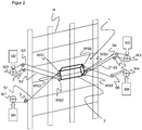
- FIG. 2 is a schematic representation of a second alternative embodiment of a conveyor device 1 according to the invention for conveying objects shown, which consists of a so-called cable robot.
- the conveying device 1 comprises a transport platform 2, on which an object can be positioned.
- the conveyor device 1 in the exemplary embodiment shown is shown as an end effector of a high-bay warehouse H, in which the transport platform 2 of the conveyor device 1 can be positioned in front of shelves of the high-bay warehouse H to unload objects from the transport platform 2 or loaded into the transport platform 2.
- the transport platform 2 is connected to four drive motors M1 to M4 by means of six connecting cables S1 to S6, the connecting cables S1 to S6 being wound onto respective winches W1 to W4.
- the drive motors M1 to M4 drive the respective winches W1 to W4 in such a way that the connecting cables S1 to S6 wound on the respective winches W1 to W4 are wound off or wound up so that the transport platform 2 is in a desired position relative to a shelf of the high-bay warehouse H is moved.
- connecting cables S2 and S3 are wound on the winch W2 and the connecting cables S4 and S5 on the winch W3.
- the winch W2 is driven by the drive motor M2 and the winch W3 is driven by the drive motor M3.
- the four named connecting cables S2, S3, S4 and S5 are arranged at four corners of a bottom plate of the transport platform 2, so that these connecting cables S2, S3, S4 and S5 essentially move the bottom plate of the transport platform 2.
- the connecting cable S1 is wound on the winch W1, which is driven by the drive motor M1.
- the connecting cable S6 is wound on the winch W4, which is also driven by its own drive motor M4.
- the six connecting cables S1 to S6 are each provided at a connecting cable end with an angle sensor WS1 to WS6 so that each connecting cable end has an angle sensor WS1 to WS6 on the transporting platform 2, respectively.
- each one angle sensor WS1 to WS6 is arranged on a respective connecting cable end to the transport platform 2.
- the angle sensor WS1 to WS6 can serve as a direct connection between the respective connecting cable end and the transport platform 2 or be integrated into a connecting unit between the respective connecting cable end and the transport platform 2.
- Each angle sensor WS1 to WS6 determines and communicates an angle between the respective connecting line S1 to S6 and a respective vertical edge of the transport platform 2 as an angle signal to a controller, not shown, which calculates an absolute pose and orientation of the transport platform 2 in three-dimensional space and the drive motors M1 to M4 accordingly controls, so that the transport platform 2 can be positioned precisely in front of a desired shelf of the high-bay warehouse H.
- the connecting cables S1 to S6 are deflected by pulleys 3a to 3f, so that a possible inaccuracy in the determination of the pose and orientation of the transport platform 2 due to the deflection can be neglected.
- the angle sensor WS1 to WS6 is a rotary encoder or an inertial measuring unit, the rotary encoder, in particular a single or multi-turn absolute encoder and the inertial measuring unit, in particular from a combination of a three-axis acceleration sensor, in particular a tilt sensor and a three-axis rotation rate sensor consists.
- the transport platform 2 of the embodiment shown comprises a cage in which the object can be loaded and unloaded by means of actuators.
- the transport platform 2 can according to an embodiment not shown also consist of a cage designed in this way, in which a person can take a seat. That is, the transport platform 2 serves as a so-called end effector of the conveyor device 1 or as a platform for a simulator.
- the transport platform 2 is connected by eight connecting cables S1 to S8 with four drive motors M1 to M4.
- connection cables S1 and S2, S3 and S4, S5 and S6 as well as S7 and S8 are wound as a pair on a respective winch W1 to W4, which are driven by the respective drive motors M1 to M4.
- the pairs of connection cables S1 and S2, S3 and S4, S5 and S6 and S7 and S8 are connected at corners of a common horizontal edge of the transport platform 2.
- an angle sensor WS1 to WS8 is arranged on the transport platform 2 at a respective connecting cable end of a connecting cable S1 to S8. That is, in this embodiment, eight angle sensors WS1 to WS8 are provided. The eight angle sensors WS1 to WS8 each supply an angle signal to the controller, not shown, so that the controller can determine the pose of the transport platform 2 even more precisely.
- each connecting cable S1 to S8 can advantageously be provided for each connecting cable S1 to S8 a separate winch with its own drive motor, so that in the embodiment of FIG. 3
- eight winches and eight drive motors instead of the illustrated four winches W1 to W4 and four drive motors M1 to M4 can be arranged.
- the completely independent control of the connecting cables S1 to S8 allows increased flexibility of the conveyor device 1 in space.
- Three-dimensional space requires six angle signals, ie six angle sensors.
- six angle sensors WS1 to WS6 are provided so that a precise determination of the pose and orientation of the transport platform 2 in three-dimensional space is possible.
- eight angle sensors WS1 to WS8 are provided, so that the overdetermined system allows a combination of the angle signals by means of suitable sensor data fusion algorithms to increase the accuracy of the determination of the pose and orientation of the transport platform 2.
- the angle signals of certain angle sensors WS1 - WS3 or WS4 - WS6 in FIG. 2 or WS1 - WS4 or WS5 - WS8 in FIG. 3 to use for determining the absolute position and orientation of the transport platform 2 in the room. That is, for example, the transport platform 2 is closer to a left side of the high-bay warehouse H and thus further away from a right side of the high-bay warehouse H, so are the angle signals of the arranged on the left side of the transport platform 2 angle sensors, WS1 to WS3 in FIG. 2 or WS1 - WS 4 in FIG.
- the transport platform 2 is suspended from the slippery traction means, which are shown in the form of the connecting cables S1 to S4, wherein the connecting cable lengths of the connecting cables S1 to S4 between the transport platform 2 and the pulleys 3 are shown.
- this system of equations can be solved numerically and accordingly supplies the absolute position and the tilt angle ⁇ of the transport platform 2.
- the determination of the pose and orientation of the transport platform 2 in three-dimensional space can be accurately determined by the provision of at least six angle sensors WS1 to WS6.
- the drive motors M1 to M4 each comprise an engine feedback system that provides data for determining the moving link pitch.
- a multi-turn rotary encoder can be provided in each pulley 3, which also provides data for determining the moving connection cable length between the transport platform 2 and the pulleys 3. These data can be taken into account when determining the pose and orientation of the transport platform 2, so that the determination can be even more accurate.
- the control is designed such that the transport platform 2 is moved in predetermined positions and the angle sensors WS1 to WS8 are calibrated in the predetermined positions.
- the transport platform 2 is moved to individual positions with respect to the high-bay warehouse H, where the angle sensors WS1 to WS8 are calibrated.
- an external reference detection system is provided which detects an accurate positioning of the transport platform 2 in the predetermined individual positions and confirmed to the controller.
- the reference detection system preferably includes a camera and markers.
- the camera may be spaced from the transport platform 2 and the markers may be disposed on the transport platform 2.
- the Camera also on the transport platform 2 and the markers can be arranged spaced from the transport platform 2.
- the data of the reference detection system can be created in a table, so that a one-time calibration is feasible.
- the data of the reference detection system can be used during operation for recalibration of the angle sensors WS1 to WS8.
- the current data can be compared with the stored data.
- the created data in the table can be updated.
- inertial measuring units in the form of three-axis acceleration sensors, can be used on the connecting cable ends on the transport platform 2, wherein the three-axis acceleration sensors each determine an angle relative to the normal force or gravitational acceleration.
- yaw rate sensors can be used to calculate by integration of the angular changes angular positions.
- an acceleration of the transport platform 2 in the xy plane can also be calculated from the data of the three-axis acceleration sensor and three-axis rotation rate sensor, so that this information can be taken into account for the position of the other connection cable ends. That is, especially in this case, only one additional rotation rate sensor is required for every six to eight connection lines S1 to S8 and six to eight acceleration sensors on the connection lines S1 to S8.
Landscapes
- Engineering & Computer Science (AREA)
- Robotics (AREA)
- Mechanical Engineering (AREA)
- Human Computer Interaction (AREA)
- Control Of Conveyors (AREA)
- Length Measuring Devices With Unspecified Measuring Means (AREA)
Applications Claiming Priority (1)
| Application Number | Priority Date | Filing Date | Title |
|---|---|---|---|
| EP17157443.7A EP3366430B1 (fr) | 2017-02-22 | 2017-02-22 | Dispositif de transport d'objets et/ou de personnes |
Publications (3)
| Publication Number | Publication Date |
|---|---|
| EP3366432A1 true EP3366432A1 (fr) | 2018-08-29 |
| EP3366432B1 EP3366432B1 (fr) | 2020-01-08 |
| EP3366432B8 EP3366432B8 (fr) | 2022-08-17 |
Family
ID=58191275
Family Applications (3)
| Application Number | Title | Priority Date | Filing Date |
|---|---|---|---|
| EP17157443.7A Active EP3366430B1 (fr) | 2017-02-22 | 2017-02-22 | Dispositif de transport d'objets et/ou de personnes |
| EP18154755.5A Active EP3366431B1 (fr) | 2017-02-22 | 2018-02-01 | Dispositif de transport d'objets et/ou de personnes |
| EP18154762.1A Active EP3366432B8 (fr) | 2017-02-22 | 2018-02-01 | Système de mesure et dispositif de transport |
Family Applications Before (2)
| Application Number | Title | Priority Date | Filing Date |
|---|---|---|---|
| EP17157443.7A Active EP3366430B1 (fr) | 2017-02-22 | 2017-02-22 | Dispositif de transport d'objets et/ou de personnes |
| EP18154755.5A Active EP3366431B1 (fr) | 2017-02-22 | 2018-02-01 | Dispositif de transport d'objets et/ou de personnes |
Country Status (1)
| Country | Link |
|---|---|
| EP (3) | EP3366430B1 (fr) |
Families Citing this family (3)
| Publication number | Priority date | Publication date | Assignee | Title |
|---|---|---|---|---|
| CN110817755A (zh) * | 2019-11-19 | 2020-02-21 | 西安电子科技大学 | 一种大范围立面作业索牵引平动运动平台及方法 |
| CN115741659A (zh) * | 2022-12-09 | 2023-03-07 | 哈尔滨工业大学(深圳) | 一种基于惯量飞轮姿态调节的绳驱无人机 |
| CN115818480B (zh) * | 2022-12-30 | 2026-03-27 | 北京史河科技有限公司 | 一种索驱机器人用卷扬机控制装置及其控制方法 |
Citations (4)
| Publication number | Priority date | Publication date | Assignee | Title |
|---|---|---|---|---|
| DE102010015530A1 (de) * | 2010-04-20 | 2010-10-14 | Sandra Wahle | Lagersystem, insbesondere Regallager |
| DE112011103897T5 (de) * | 2010-11-24 | 2013-08-22 | Samsung Heavy Ind. Co., Ltd. | System und Verfahren zum Steuern einer autonomen Plattform, die ein Seil verwendet |
| US20130292543A1 (en) * | 2010-11-12 | 2013-11-07 | Samsung Heavy Ind. Co., Ltd. | Moving apparatus and method of operating the same |
| WO2016126173A1 (fr) * | 2015-02-06 | 2016-08-11 | Teknikpatrullen Ab | Système permettant le positionnement d'un outil pointu par rapport à une paroi |
-
2017
- 2017-02-22 EP EP17157443.7A patent/EP3366430B1/fr active Active
-
2018
- 2018-02-01 EP EP18154755.5A patent/EP3366431B1/fr active Active
- 2018-02-01 EP EP18154762.1A patent/EP3366432B8/fr active Active
Patent Citations (4)
| Publication number | Priority date | Publication date | Assignee | Title |
|---|---|---|---|---|
| DE102010015530A1 (de) * | 2010-04-20 | 2010-10-14 | Sandra Wahle | Lagersystem, insbesondere Regallager |
| US20130292543A1 (en) * | 2010-11-12 | 2013-11-07 | Samsung Heavy Ind. Co., Ltd. | Moving apparatus and method of operating the same |
| DE112011103897T5 (de) * | 2010-11-24 | 2013-08-22 | Samsung Heavy Ind. Co., Ltd. | System und Verfahren zum Steuern einer autonomen Plattform, die ein Seil verwendet |
| WO2016126173A1 (fr) * | 2015-02-06 | 2016-08-11 | Teknikpatrullen Ab | Système permettant le positionnement d'un outil pointu par rapport à une paroi |
Also Published As
| Publication number | Publication date |
|---|---|
| EP3366431A1 (fr) | 2018-08-29 |
| EP3366432B1 (fr) | 2020-01-08 |
| EP3366432B8 (fr) | 2022-08-17 |
| EP3366430B1 (fr) | 2019-08-07 |
| EP3366431B1 (fr) | 2019-08-07 |
| EP3366430A1 (fr) | 2018-08-29 |
Similar Documents
| Publication | Publication Date | Title |
|---|---|---|
| DE102012220036B4 (de) | Bewegungssystem, das ausgestaltet ist, um eine nutzlast inmehrere richtungen zu bewegen | |
| DE102016012065B4 (de) | Robotersystem mit Funktion zum Berechnen von Position und Ausrichtung eines Sensors | |
| DE102014005434B4 (de) | Steuerungseinrichtung für einen Roboter zur Beförderung eines Werkstücks | |
| EP2910512B1 (fr) | Procédé d'étalonnage de scanners laser sur une grue de manutention de conteneurs | |
| DE102013204789B4 (de) | Verfahren zum folgern von absichten eines bedieners zum bewegen eines robotersystems | |
| DE202013012799U1 (de) | Vorrichtung zum Entlasten eines Körpergewichts eines Benutzers während körperlicher Aktivität des Benutzers, insbesondere für das Gangtraining | |
| WO2015158501A1 (fr) | Appareil de mesure de coordonnées et procédé permettant de faire fonctionner un appareil de mesure de coordonnées | |
| EP3366432B1 (fr) | Système de mesure et dispositif de transport | |
| EP3439834B1 (fr) | Commande cartésienne d'une pointe de mât d'un manipulateur de grande dimension, en particulier une pompe à béton | |
| DE102018114644B3 (de) | Manueller Anlernvorgang an einem Robotermanipulator mit Kraft-/Momentenvorgabe | |
| DE69805330T2 (de) | Treppenaufzug | |
| DE102009056582B4 (de) | Handhabungssystem zur Bewegung eines über biegeschlaffe Elemente geführten Gegenstandes, insbesondere Bandroboter sowie dazugehöriges Arbeitsverfahren | |
| DE102023128612A1 (de) | Robotersystem zur Entlastung von Robotereinrichtungen mittels Seilrobotersystem | |
| DE112018000496T5 (de) | Werkstücktransportsteuerung und Bewegungsführungsvorrichtung | |
| EP2789971A1 (fr) | Procédé de calibrage d'un dispositif de détection et dispositif de détection | |
| DE102010056607A1 (de) | Kontinuierliche oder quasikontinuierliche kinematische Kette mit einem sensorischen System | |
| DE102013022533B3 (de) | Verfahren zum robotergestützten Stapeln von Gegenständen | |
| DE102021121818A1 (de) | Turmdrehkran, Verfahren und Steuerungseinheit zum Betreiben eines Turmdrehkrans, Laufkatze und Katzfahrwerk | |
| WO2022028828A1 (fr) | Dispositif et procédé permettant de capturer des vitesses de segments de bras d'un robot | |
| WO2024084066A1 (fr) | Système de robot pour soulager des dispositifs de robot au moyen d'un système de robot à câbles | |
| DE10137955A1 (de) | Verfahren zur Bewegungskommandierung eines Serviceroboters | |
| DE102019102453A1 (de) | Verstellbares Gegengewicht für einen Robotermanipulator | |
| EP3589456A1 (fr) | Cinématique parallèle | |
| DE102024107151B3 (de) | Verfahren zum Berechnen der Qualität einer Roboterentlastungseinrichtung eines Robotersystem | |
| EP4367347B1 (fr) | Procede de reglage automatique d'une position variable d'un poteau de distribution reglable d'un dispositif de pompe de construction et/ou de pompe pour matieres epaisses et systeme |
Legal Events
| Date | Code | Title | Description |
|---|---|---|---|
| PUAI | Public reference made under article 153(3) epc to a published international application that has entered the european phase |
Free format text: ORIGINAL CODE: 0009012 |
|
| STAA | Information on the status of an ep patent application or granted ep patent |
Free format text: STATUS: THE APPLICATION HAS BEEN PUBLISHED |
|
| AK | Designated contracting states |
Kind code of ref document: A1 Designated state(s): AL AT BE BG CH CY CZ DE DK EE ES FI FR GB GR HR HU IE IS IT LI LT LU LV MC MK MT NL NO PL PT RO RS SE SI SK SM TR |
|
| AX | Request for extension of the european patent |
Extension state: BA ME |
|
| STAA | Information on the status of an ep patent application or granted ep patent |
Free format text: STATUS: REQUEST FOR EXAMINATION WAS MADE |
|
| 17P | Request for examination filed |
Effective date: 20181212 |
|
| RBV | Designated contracting states (corrected) |
Designated state(s): AL AT BE BG CH CY CZ DE DK EE ES FI FR GB GR HR HU IE IS IT LI LT LU LV MC MK MT NL NO PL PT RO RS SE SI SK SM TR |
|
| STAA | Information on the status of an ep patent application or granted ep patent |
Free format text: STATUS: EXAMINATION IS IN PROGRESS |
|
| 17Q | First examination report despatched |
Effective date: 20190319 |
|
| GRAP | Despatch of communication of intention to grant a patent |
Free format text: ORIGINAL CODE: EPIDOSNIGR1 |
|
| STAA | Information on the status of an ep patent application or granted ep patent |
Free format text: STATUS: GRANT OF PATENT IS INTENDED |
|
| GRAS | Grant fee paid |
Free format text: ORIGINAL CODE: EPIDOSNIGR3 |
|
| INTG | Intention to grant announced |
Effective date: 20191106 |
|
| GRAA | (expected) grant |
Free format text: ORIGINAL CODE: 0009210 |
|
| STAA | Information on the status of an ep patent application or granted ep patent |
Free format text: STATUS: THE PATENT HAS BEEN GRANTED |
|
| AK | Designated contracting states |
Kind code of ref document: B1 Designated state(s): AL AT BE BG CH CY CZ DE DK EE ES FI FR GB GR HR HU IE IS IT LI LT LU LV MC MK MT NL NO PL PT RO RS SE SI SK SM TR |
|
| REG | Reference to a national code |
Ref country code: GB Ref legal event code: FG4D Free format text: NOT ENGLISH |
|
| REG | Reference to a national code |
Ref country code: CH Ref legal event code: EP |
|
| RAP2 | Party data changed (patent owner data changed or rights of a patent transferred) |
Owner name: SICK STEGMANN GMBH Owner name: UNIVERSITAET DUISBURG-ESSEN |
|
| REG | Reference to a national code |
Ref country code: DE Ref legal event code: R096 Ref document number: 502018000598 Country of ref document: DE |
|
| REG | Reference to a national code |
Ref country code: CH Ref legal event code: PK Free format text: BERICHTIGUNG B8 |
|
| REG | Reference to a national code |
Ref country code: IE Ref legal event code: FG4D Free format text: LANGUAGE OF EP DOCUMENT: GERMAN |
|
| REG | Reference to a national code |
Ref country code: AT Ref legal event code: REF Ref document number: 1222118 Country of ref document: AT Kind code of ref document: T Effective date: 20200215 |
|
| REG | Reference to a national code |
Ref country code: NL Ref legal event code: MP Effective date: 20200108 |
|
| REG | Reference to a national code |
Ref country code: LT Ref legal event code: MG4D |
|
| PG25 | Lapsed in a contracting state [announced via postgrant information from national office to epo] |
Ref country code: NO Free format text: LAPSE BECAUSE OF FAILURE TO SUBMIT A TRANSLATION OF THE DESCRIPTION OR TO PAY THE FEE WITHIN THE PRESCRIBED TIME-LIMIT Effective date: 20200408 Ref country code: FI Free format text: LAPSE BECAUSE OF FAILURE TO SUBMIT A TRANSLATION OF THE DESCRIPTION OR TO PAY THE FEE WITHIN THE PRESCRIBED TIME-LIMIT Effective date: 20200108 Ref country code: RS Free format text: LAPSE BECAUSE OF FAILURE TO SUBMIT A TRANSLATION OF THE DESCRIPTION OR TO PAY THE FEE WITHIN THE PRESCRIBED TIME-LIMIT Effective date: 20200108 Ref country code: NL Free format text: LAPSE BECAUSE OF FAILURE TO SUBMIT A TRANSLATION OF THE DESCRIPTION OR TO PAY THE FEE WITHIN THE PRESCRIBED TIME-LIMIT Effective date: 20200108 Ref country code: LT Free format text: LAPSE BECAUSE OF FAILURE TO SUBMIT A TRANSLATION OF THE DESCRIPTION OR TO PAY THE FEE WITHIN THE PRESCRIBED TIME-LIMIT Effective date: 20200108 Ref country code: PT Free format text: LAPSE BECAUSE OF FAILURE TO SUBMIT A TRANSLATION OF THE DESCRIPTION OR TO PAY THE FEE WITHIN THE PRESCRIBED TIME-LIMIT Effective date: 20200531 |
|
| PG25 | Lapsed in a contracting state [announced via postgrant information from national office to epo] |
Ref country code: GR Free format text: LAPSE BECAUSE OF FAILURE TO SUBMIT A TRANSLATION OF THE DESCRIPTION OR TO PAY THE FEE WITHIN THE PRESCRIBED TIME-LIMIT Effective date: 20200409 Ref country code: BG Free format text: LAPSE BECAUSE OF FAILURE TO SUBMIT A TRANSLATION OF THE DESCRIPTION OR TO PAY THE FEE WITHIN THE PRESCRIBED TIME-LIMIT Effective date: 20200408 Ref country code: IS Free format text: LAPSE BECAUSE OF FAILURE TO SUBMIT A TRANSLATION OF THE DESCRIPTION OR TO PAY THE FEE WITHIN THE PRESCRIBED TIME-LIMIT Effective date: 20200508 Ref country code: SE Free format text: LAPSE BECAUSE OF FAILURE TO SUBMIT A TRANSLATION OF THE DESCRIPTION OR TO PAY THE FEE WITHIN THE PRESCRIBED TIME-LIMIT Effective date: 20200108 Ref country code: LV Free format text: LAPSE BECAUSE OF FAILURE TO SUBMIT A TRANSLATION OF THE DESCRIPTION OR TO PAY THE FEE WITHIN THE PRESCRIBED TIME-LIMIT Effective date: 20200108 Ref country code: HR Free format text: LAPSE BECAUSE OF FAILURE TO SUBMIT A TRANSLATION OF THE DESCRIPTION OR TO PAY THE FEE WITHIN THE PRESCRIBED TIME-LIMIT Effective date: 20200108 |
|
| REG | Reference to a national code |
Ref country code: DE Ref legal event code: R097 Ref document number: 502018000598 Country of ref document: DE |
|
| REG | Reference to a national code |
Ref country code: BE Ref legal event code: MM Effective date: 20200229 |
|
| PG25 | Lapsed in a contracting state [announced via postgrant information from national office to epo] |
Ref country code: MC Free format text: LAPSE BECAUSE OF FAILURE TO SUBMIT A TRANSLATION OF THE DESCRIPTION OR TO PAY THE FEE WITHIN THE PRESCRIBED TIME-LIMIT Effective date: 20200108 Ref country code: ES Free format text: LAPSE BECAUSE OF FAILURE TO SUBMIT A TRANSLATION OF THE DESCRIPTION OR TO PAY THE FEE WITHIN THE PRESCRIBED TIME-LIMIT Effective date: 20200108 Ref country code: LU Free format text: LAPSE BECAUSE OF NON-PAYMENT OF DUE FEES Effective date: 20200201 Ref country code: SK Free format text: LAPSE BECAUSE OF FAILURE TO SUBMIT A TRANSLATION OF THE DESCRIPTION OR TO PAY THE FEE WITHIN THE PRESCRIBED TIME-LIMIT Effective date: 20200108 Ref country code: RO Free format text: LAPSE BECAUSE OF FAILURE TO SUBMIT A TRANSLATION OF THE DESCRIPTION OR TO PAY THE FEE WITHIN THE PRESCRIBED TIME-LIMIT Effective date: 20200108 Ref country code: CZ Free format text: LAPSE BECAUSE OF FAILURE TO SUBMIT A TRANSLATION OF THE DESCRIPTION OR TO PAY THE FEE WITHIN THE PRESCRIBED TIME-LIMIT Effective date: 20200108 Ref country code: EE Free format text: LAPSE BECAUSE OF FAILURE TO SUBMIT A TRANSLATION OF THE DESCRIPTION OR TO PAY THE FEE WITHIN THE PRESCRIBED TIME-LIMIT Effective date: 20200108 Ref country code: DK Free format text: LAPSE BECAUSE OF FAILURE TO SUBMIT A TRANSLATION OF THE DESCRIPTION OR TO PAY THE FEE WITHIN THE PRESCRIBED TIME-LIMIT Effective date: 20200108 Ref country code: SM Free format text: LAPSE BECAUSE OF FAILURE TO SUBMIT A TRANSLATION OF THE DESCRIPTION OR TO PAY THE FEE WITHIN THE PRESCRIBED TIME-LIMIT Effective date: 20200108 |
|
| PLBE | No opposition filed within time limit |
Free format text: ORIGINAL CODE: 0009261 |
|
| STAA | Information on the status of an ep patent application or granted ep patent |
Free format text: STATUS: NO OPPOSITION FILED WITHIN TIME LIMIT |
|
| 26N | No opposition filed |
Effective date: 20201009 |
|
| PG25 | Lapsed in a contracting state [announced via postgrant information from national office to epo] |
Ref country code: IT Free format text: LAPSE BECAUSE OF FAILURE TO SUBMIT A TRANSLATION OF THE DESCRIPTION OR TO PAY THE FEE WITHIN THE PRESCRIBED TIME-LIMIT Effective date: 20200108 Ref country code: IE Free format text: LAPSE BECAUSE OF NON-PAYMENT OF DUE FEES Effective date: 20200201 |
|
| PG25 | Lapsed in a contracting state [announced via postgrant information from national office to epo] |
Ref country code: PL Free format text: LAPSE BECAUSE OF FAILURE TO SUBMIT A TRANSLATION OF THE DESCRIPTION OR TO PAY THE FEE WITHIN THE PRESCRIBED TIME-LIMIT Effective date: 20200108 Ref country code: SI Free format text: LAPSE BECAUSE OF FAILURE TO SUBMIT A TRANSLATION OF THE DESCRIPTION OR TO PAY THE FEE WITHIN THE PRESCRIBED TIME-LIMIT Effective date: 20200108 Ref country code: BE Free format text: LAPSE BECAUSE OF NON-PAYMENT OF DUE FEES Effective date: 20200229 |
|
| REG | Reference to a national code |
Ref country code: DE Ref legal event code: R081 Ref document number: 502018000598 Country of ref document: DE Owner name: UNIVERSITAET DUISBURG-ESSEN, KOERPERSCHAFT DES, DE Free format text: FORMER OWNER: SICK STEGMANN GMBH, 78166 DONAUESCHINGEN, DE Ref country code: DE Ref legal event code: R081 Ref document number: 502018000598 Country of ref document: DE Owner name: SICK AG, DE Free format text: FORMER OWNER: SICK STEGMANN GMBH, 78166 DONAUESCHINGEN, DE Ref country code: DE Ref legal event code: R082 Ref document number: 502018000598 Country of ref document: DE Representative=s name: LUDEWIGT, CHRISTOPH, DR., DE |
|
| PG25 | Lapsed in a contracting state [announced via postgrant information from national office to epo] |
Ref country code: LI Free format text: LAPSE BECAUSE OF NON-PAYMENT OF DUE FEES Effective date: 20210228 Ref country code: CH Free format text: LAPSE BECAUSE OF NON-PAYMENT OF DUE FEES Effective date: 20210228 |
|
| PG25 | Lapsed in a contracting state [announced via postgrant information from national office to epo] |
Ref country code: TR Free format text: LAPSE BECAUSE OF FAILURE TO SUBMIT A TRANSLATION OF THE DESCRIPTION OR TO PAY THE FEE WITHIN THE PRESCRIBED TIME-LIMIT Effective date: 20200108 Ref country code: MT Free format text: LAPSE BECAUSE OF FAILURE TO SUBMIT A TRANSLATION OF THE DESCRIPTION OR TO PAY THE FEE WITHIN THE PRESCRIBED TIME-LIMIT Effective date: 20200108 Ref country code: CY Free format text: LAPSE BECAUSE OF FAILURE TO SUBMIT A TRANSLATION OF THE DESCRIPTION OR TO PAY THE FEE WITHIN THE PRESCRIBED TIME-LIMIT Effective date: 20200108 |
|
| PGFP | Annual fee paid to national office [announced via postgrant information from national office to epo] |
Ref country code: FR Payment date: 20220221 Year of fee payment: 5 |
|
| PG25 | Lapsed in a contracting state [announced via postgrant information from national office to epo] |
Ref country code: MK Free format text: LAPSE BECAUSE OF FAILURE TO SUBMIT A TRANSLATION OF THE DESCRIPTION OR TO PAY THE FEE WITHIN THE PRESCRIBED TIME-LIMIT Effective date: 20200108 Ref country code: AL Free format text: LAPSE BECAUSE OF FAILURE TO SUBMIT A TRANSLATION OF THE DESCRIPTION OR TO PAY THE FEE WITHIN THE PRESCRIBED TIME-LIMIT Effective date: 20200108 |
|
| GRAT | Correction requested after decision to grant or after decision to maintain patent in amended form |
Free format text: ORIGINAL CODE: EPIDOSNCDEC |
|
| PLAA | Information modified related to event that no opposition was filed |
Free format text: ORIGINAL CODE: 0009299DELT |
|
| PLBE | No opposition filed within time limit |
Free format text: ORIGINAL CODE: 0009261 |
|
| REG | Reference to a national code |
Ref country code: CH Ref legal event code: PK Free format text: BERICHTIGUNG B8 Ref country code: CH Ref legal event code: PK Free format text: BERICHTIGUNGEN |
|
| R26N | No opposition filed (corrected) |
Effective date: 20201009 |
|
| RIN2 | Information on inventor provided after grant (corrected) |
Inventor name: REICHERT, CHRISTOPHER Inventor name: BRUCKMANN, TOBIAS Inventor name: HOFMANN, TOBIAS Inventor name: MERKLE, CLEMENS Inventor name: HUMMEL, MARTIN Inventor name: BRUGGER, SIMON Inventor name: SELLMER, CHRISTIAN |
|
| REG | Reference to a national code |
Ref country code: DE Ref legal event code: R081 Ref document number: 502018000598 Country of ref document: DE Owner name: UNIVERSITAET DUISBURG-ESSEN, KOERPERSCHAFT DES, DE Free format text: FORMER OWNER: SICK AG, 79183 WALDKIRCH, DE Ref country code: DE Ref legal event code: R081 Ref document number: 502018000598 Country of ref document: DE Owner name: SICK AG, DE Free format text: FORMER OWNER: SICK AG, 79183 WALDKIRCH, DE Ref country code: DE Ref legal event code: R082 Ref document number: 502018000598 Country of ref document: DE Representative=s name: LUDEWIGT, CHRISTOPH, DR., DE |
|
| GBPC | Gb: european patent ceased through non-payment of renewal fee |
Effective date: 20220201 |
|
| PG25 | Lapsed in a contracting state [announced via postgrant information from national office to epo] |
Ref country code: GB Free format text: LAPSE BECAUSE OF NON-PAYMENT OF DUE FEES Effective date: 20220201 |
|
| PG25 | Lapsed in a contracting state [announced via postgrant information from national office to epo] |
Ref country code: FR Free format text: LAPSE BECAUSE OF NON-PAYMENT OF DUE FEES Effective date: 20230228 |
|
| REG | Reference to a national code |
Ref country code: AT Ref legal event code: MM01 Ref document number: 1222118 Country of ref document: AT Kind code of ref document: T Effective date: 20230201 |
|
| PG25 | Lapsed in a contracting state [announced via postgrant information from national office to epo] |
Ref country code: AT Free format text: LAPSE BECAUSE OF NON-PAYMENT OF DUE FEES Effective date: 20230201 |
|
| PG25 | Lapsed in a contracting state [announced via postgrant information from national office to epo] |
Ref country code: AT Free format text: LAPSE BECAUSE OF NON-PAYMENT OF DUE FEES Effective date: 20230201 |
|
| PGFP | Annual fee paid to national office [announced via postgrant information from national office to epo] |
Ref country code: DE Payment date: 20260217 Year of fee payment: 9 |
|
| PGFP | Annual fee paid to national office [announced via postgrant information from national office to epo] |
Ref country code: AT Payment date: 20260410 Year of fee payment: 5 |