EP4367347B1 - Procede de reglage automatique d'une position variable d'un poteau de distribution reglable d'un dispositif de pompe de construction et/ou de pompe pour matieres epaisses et systeme - Google Patents
Procede de reglage automatique d'une position variable d'un poteau de distribution reglable d'un dispositif de pompe de construction et/ou de pompe pour matieres epaisses et systeme Download PDFInfo
- Publication number
- EP4367347B1 EP4367347B1 EP22738466.6A EP22738466A EP4367347B1 EP 4367347 B1 EP4367347 B1 EP 4367347B1 EP 22738466 A EP22738466 A EP 22738466A EP 4367347 B1 EP4367347 B1 EP 4367347B1
- Authority
- EP
- European Patent Office
- Prior art keywords
- boom
- actual
- determining
- mast
- variable
- Prior art date
- Legal status (The legal status is an assumption and is not a legal conclusion. Google has not performed a legal analysis and makes no representation as to the accuracy of the status listed.)
- Active
Links
Images


Classifications
-
- E—FIXED CONSTRUCTIONS
- E04—BUILDING
- E04G—SCAFFOLDING; FORMS; SHUTTERING; BUILDING IMPLEMENTS OR AIDS, OR THEIR USE; HANDLING BUILDING MATERIALS ON THE SITE; REPAIRING, BREAKING-UP OR OTHER WORK ON EXISTING BUILDINGS
- E04G21/00—Preparing, conveying, or working-up building materials or building elements in situ; Other devices or measures for constructional work
- E04G21/02—Conveying or working-up concrete or similar masses able to be heaped or cast
- E04G21/04—Devices for both conveying and distributing
- E04G21/0418—Devices for both conveying and distributing with distribution hose
- E04G21/0445—Devices for both conveying and distributing with distribution hose with booms
- E04G21/0463—Devices for both conveying and distributing with distribution hose with booms with boom control mechanisms, e.g. to automate concrete distribution
-
- B—PERFORMING OPERATIONS; TRANSPORTING
- B66—HOISTING; LIFTING; HAULING
- B66C—CRANES; LOAD-ENGAGING ELEMENTS OR DEVICES FOR CRANES, CAPSTANS, WINCHES, OR TACKLES
- B66C23/00—Cranes comprising essentially a beam, boom, or triangular structure acting as a cantilever and mounted for translatory of swinging movements in vertical or horizontal planes or a combination of such movements, e.g. jib-cranes, derricks, tower cranes
- B66C23/62—Constructional features or details
- B66C23/64—Jibs
- B66C23/68—Jibs foldable or otherwise adjustable in configuration
-
- B—PERFORMING OPERATIONS; TRANSPORTING
- B66—HOISTING; LIFTING; HAULING
- B66C—CRANES; LOAD-ENGAGING ELEMENTS OR DEVICES FOR CRANES, CAPSTANS, WINCHES, OR TACKLES
- B66C23/00—Cranes comprising essentially a beam, boom, or triangular structure acting as a cantilever and mounted for translatory of swinging movements in vertical or horizontal planes or a combination of such movements, e.g. jib-cranes, derricks, tower cranes
- B66C23/88—Safety gear
-
- E—FIXED CONSTRUCTIONS
- E04—BUILDING
- E04G—SCAFFOLDING; FORMS; SHUTTERING; BUILDING IMPLEMENTS OR AIDS, OR THEIR USE; HANDLING BUILDING MATERIALS ON THE SITE; REPAIRING, BREAKING-UP OR OTHER WORK ON EXISTING BUILDINGS
- E04G21/00—Preparing, conveying, or working-up building materials or building elements in situ; Other devices or measures for constructional work
- E04G21/02—Conveying or working-up concrete or similar masses able to be heaped or cast
- E04G21/04—Devices for both conveying and distributing
- E04G21/0418—Devices for both conveying and distributing with distribution hose
- E04G21/0436—Devices for both conveying and distributing with distribution hose on a mobile support, e.g. truck
Definitions
- the invention relates to a method for automatically adjusting a variable mast position of an adjustable distribution boom of a construction and/or thick matter pumping device and a system.
- the EP 2 813 643 A1 discloses a stability control system for pump trucks comprising a detection device and a control device, wherein the detection device is used to detect current pumping state parameters, boom posture parameters, landing posture parameters, pump truck body position state parameters, and current numerical signals of external load parameters acting on a boom system of the pump truck, and wherein the control device is used to receive the current numerical signals of the above parameters, calculate the overall machine center of gravity position of the concrete pump truck according to the parameters, and perform stability control for the pump truck according to the overall machine center of gravity position within a pump truck stability range.
- the stability control system comprehensively considers the pump truck's inherent factors and the influencing factors of external load, the calculation accuracy of the center of gravity is high, and the construction safety of the concrete pump truck is improved.
- the EP 2 813 643 A1 a method for stability control of a pump truck and a pump truck including the stability control system of the pump truck.
- the WO 2018/115270 A1 reveals a mobile large manipulator.
- the invention is based on the object of providing a method for automatically adjusting a variable mast position of an adjustable distribution boom of a construction and/or thick matter pumping device and a system, in particular which has improved properties in each case.
- the invention solves this problem by providing a method having the features of claim 1 and a system having the features of claim 7.
- Advantageous developments and/or embodiments of the invention are described in the dependent claims.
- the inventive, in particular automatic, method is designed, configured, or provided for automatically adjusting a variable mast position of a, in particular flexibly adjustable, distribution boom of a construction and/or slurry pumping device. At least one identical tip position of a mast tip of the distribution boom can be achieved through different mast positions or mast poses, in particular of the distribution boom.
- the method comprises or has the step of: determining, in particular automatically determining, and adjusting, in particular automatically adjusting, a mast position, in particular at least one value of the mast position, in particular of the distribution boom, depending on a predetermined variable or a parameter, in particular a value of the variable, determining a tip position, in particular a value of the tip position, in particular of the mast tip, and based on, in particular at least one optimization criterion.
- the optimization criterion is a minimized or reduced, particularly mechanical, tipping or load moment, in particular a minimized value of the tipping moment, of the placing boom in relation to a support system, in particular the placing boom, the construction and/or slurry pumping device.
- the tipping moment depends on the boom position.
- the distribution boom can be a construction and/or thick material distribution boom.
- the construction and/or thick matter pump device can be mobile, in particular mobile, in particular a car construction and/or thick matter pump.
- the construction and/or thick matter pump device can be designed to pump construction and/or thick matter.
- Building material can refer to mortar, cement, screed, concrete, and/or plaster. Additionally or alternatively, thick matter can refer to sludge.
- At least the same top position of the mast tip can be achieved by at least three, in particular at least ten, different mast positions.
- the mast tip can be a free end of the distribution boom.
- the variable determining the tip position can be a target variable and/or determining a target tip position, in particular of the mast tip. Additionally or alternatively, the variable can be a direction, in particular a target direction, and/or a speed, in particular a target speed, of a movement, in particular a target movement, of the mast tip. Further additionally or alternatively, the variable can be a travel command or travel command, in particular to reach the tip position. Further additionally or alternatively, the variable can be specified by an operator or user, in particular of the distribution boom and/or the construction and/or thick matter pump device. Further additionally or alternatively, the method can comprise the step of determining, in particular detecting, a specification of the variable, in particular by the operator.
- optimization criterion can be maintaining a distance from at least one obstacle, such as a remainder of the construction and/or thick matter pumping device and/or another distribution boom, by the distribution boom.
- the tipping moment of the placing boom can be relative to or at a base of the placing boom, particularly a four-point bearing. Additionally or alternatively, the tipping moment can be caused by the boom position.
- the step comprises: determining, in particular automatically determining and/or searching and/or calculating, and setting, in particular automatically setting, a Change, in particular of the mast position, in particular directly or without detours, starting from, in particular at, a, in particular instantaneous or current, actual mast position, in particular of the placing boom, in particular at least, based on, in particular to, a, in particular greatest, minimization, in particular of the tipping moment, in particular directly or without detours, starting from, in particular at, a, in particular instantaneous or current, actual tipping moment of the placing boom in relation to the support system.
- the actual tipping moment depends on the actual mast position.
- determining and setting a mast position to a, in particular nearest, locally minimized or minimum tipping moment This enables a local and/or, in particular thus, simple and/or rapid minimization of the tipping moment, in particular and thereby achieving and/or maintaining the peak position, in particular the target peak position.
- the tipping moment minimized in this way does not need to be or can be a globally minimized or minimum tipping moment.
- the phrase "a, in particular steepest, descent" can be used synonymously with the phrase "a, in particular greatest, minimization.”
- the method can be referred to as a gradient-based method.
- the method can comprise the step of determining, in particular recording, the actual mast position.
- the step comprises: controlling, in particular automatically controlling and/or regulating, the boom position to, in particular, reach and/or maintain the peak position, in particular the target peak position, in particular starting from the, in particular instantaneous or current, actual peak position of the distribution boom and/or during the determination and adjustment of the change and/or as long as the actual tipping moment is minimized, if provided.
- the method can comprise the step of: determining, in particular detecting, the actual peak position.
- the step comprises: determining and adjusting the change and controlling, in particular regulating, the mast position by determining, in particular automatically determining and/or searching and/or calculating, a solution, in particular a value of the solution, for a kinematic relationship, in particular at least the minimization of the actual tipping moment and the achievement and/or maintenance of the peak position.
- a solution in particular a value of the solution
- the kinematic relationship can Describe, in particular model, minimization of the tipping moment and the achievement and/or maintenance of the peak position.
- achieving and/or maintaining the peak position can take priority over, in particular further, minimization of the tipping moment.
- the mast tip can reach and/or maintain the peak position and the tipping moment does or cannot reach a, in particular the next, local minimum, in particular completely.
- the kinematic relationship can take into account, in particular have, adjustment ranges.
- the distribution boom comprises or has a plurality of, in particular flexibly, adjustable mast joints.
- the mast position can be changed by a changeable joint position combination or configuration of the mast joints.
- at least the same peak position can be achieved by different joint position combinations, in particular of the mast joints.
- the mast joints have or have different, in particular the different, adjustment ranges, in particular different values of the adjustment ranges.
- the step comprises: determining, in particular automatically determining, and setting, in particular automatically setting, a joint position combination, in particular at least one value of the joint position combination, in particular of the mast joints, depending on the predetermined variable and based on, in particular at least, the optimization criterion, in particular and taking into account the adjustment ranges.
- the tipping moment depends on the joint position combination.
- at least one of the mast joints can have, in particular be, an articulated, rotary and/or sliding joint.
- at least one of the adjustment ranges can have, in particular be, an angular range.
- at least one of the adjustment ranges can be defined, in particular limited, by at least one, in particular mechanical, stop of at least one of the mast joints.
- the construction and/or thick matter pump device, in particular the distribution boom can have several articulated drives for adjusting the mast joints or for changing or setting the joint position combination.
- one of the mast joints can be at a non-free or fixed end or the mast base of the distribution boom.
- the distribution boom is rollable and/or Z-foldable by means of the boom joints, in particular roll-Z-foldable.
- the distribution boom comprises or has a plurality of boom segments or sections that are adjustable, in particular relative to one another and/or flexibly.
- the mast position can be changed by a variable adjustment combination or configuration of the mast segments, in particular relative to one another.
- at least the same tip position can be achieved by different adjustment combinations, in particular of the mast segments relative to one another.
- the mast segments have or have different masses, in particular different mass values, and/or different lengths, in particular different length values, and/or different center of gravity positions or centers of gravity, in particular values of the center of gravity positions.
- the step comprises: determining, in particular automatically determining, and setting, in particular automatically setting, an adjustment combination, in particular at least one value of the adjustment combination, depending on the predetermined variable and based on, in particular at least, the optimization criterion, in particular and taking into account the masses and/or the lengths and/or the center of gravity positions.
- the tipping moment depends on the adjustment combination.
- the mast segments can be adjustable by means of the mast joints.
- the construction and/or thick matter pumping device, in particular the distribution boom can have several segment drives for adjusting the boom segments or for changing or adjusting the adjustment combination.
- the support system is adjustable, in particular flexibly.
- the method comprises or has the step of: locking, in particular automatically locking, mast positions, in particular values of the mast positions, and/or tipping moments, in particular values of the tipping moments, depending on a determined variable or a determined parameter, in particular a determined value of the variable, determining at least one variable support configuration or position, in particular at least one variable value of the support configuration and/or an actual support configuration, of the adjustable support system for counteracting the tipping moment, in particular the actual tipping moment.
- This in particular the adjustable support system, enables adaptation to a, in particular local, construction site condition, in particular to a small support area.
- this enables, in particular by locking the boom positions and/or the tipping moments depending on the determined value determining at least the variable support configuration, to minimize, reduce, or lower the risk of the construction and/or slurry pumping device tipping over and/or toppling over and/or, in particular, to increase safety when working with or operating the construction and/or slurry pumping device, in particular when adjusting the placing boom. Furthermore, this enables, in particular by minimizing the tipping moment, to maximize the available working space, in particular of the placing boom.
- the support system can have support booms, in particular support legs, adjustable in a support width and/or flexibly.
- the method can comprise the step of determining, in particular detecting, the support configuration, in particular the actual support configuration.
- the distribution boom comprises or has a conveyor line, in particular a flexibly adjustable one, for conveying construction and/or high-density material.
- the conveyor line can comprise, in particular be, a pipeline.
- the system according to the invention comprises or has an adjustment device.
- the adjustment device is designed or configured for, in particular, the automatic adjustment of a, in particular the, variable mast position of a, in particular the, adjustable placing boom of a, in particular the, construction and/or slurry pumping device. At least one identical, in particular the same, tip position of a, in particular the, mast tip of the placing boom can be achieved through different, in particular the different, mast positions.
- the adjustment device is designed or configured for, in particular, the determination and adjustment of a, in particular the, mast position as a function of a, in particular the, predetermined variable, determining a, in particular the, tip position and based on an, in particular the, optimization criterion.
- the optimization criterion is a minimized, in particular the minimized, tipping moment of the placing boom with respect to a, in particular the, support system of the construction and/or slurry pumping device.
- the tipping moment depends on the mast position.
- the adjustment device is designed or configured for, in particular, determining and adjusting a, in particular the, change starting from a, in particular the, actual boom position based on a, in particular the and/or greatest, minimization starting from a, in particular the, actual tipping moment of the distribution boom with respect to the support system.
- the actual tipping moment depends on the actual boom position.
- the adjustment device is designed or configured for, in particular, controlling, in particular regulating, the boom position to, in particular, reach and/or maintain the peak position, in particular starting from the actual peak position of the distribution boom and/or during the determination and adjustment of the change and/or as long as the actual tipping moment is minimized.
- the adjustment device is designed or configured for, in particular, determining and adjusting the change and designed or configured to, in particular, control, in particular regulate, the mast position by determining a, in particular the, solution for a, in particular the, kinematic relationship between minimizing the actual tipping moment and reaching and/or maintaining the tip position.
- the system in particular the adjustment device, can be designed or configured to, in particular automatically, execute a, in particular the, previously mentioned method.
- the system can comprise the distribution boom, in particular the construction and/or thick matter pump device.
- the adjustment device can be electrical, hydraulic and/or pneumatic.
- the adjustment device can comprise a computing unit, in particular a processor, and/or a memory unit.
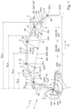
- Fig. 1 , 2 , and 3 to 10 show a system 1 according to the invention, in particular comprising an adjustment device 2, and a method according to the invention for automatically adjusting a variable mast position MS of an adjustable distribution boom 3 of a construction and/or thick matter pump device 4. At least one same tip position SPO of a mast tip 3S of the distribution boom 3 can be reached by different mast positions MS, MS'.
- the system 1, in particular the adjustment device 2 is designed, in particular determines and adjusts, a mast position MS as a function of a predetermined variable VG determining a peak position SPO and based on an optimization criterion OK.
- the method comprises the step of determining and adjusting the mast position MS as a function of the specified variable VG, determining the peak position SPO and based on the optimization criterion OK, in particular by means of the system 1, in particular the adjustment device 2.
- the optimization criterion OK is a minimized tipping moment KM of the placing boom 3 with respect to a support system 7 of the construction and/or thick matter pump device 4, in particular a boom base 3F of the placing boom 3.
- the tipping moment KM depends on the boom position MS.
- the system 1 comprises the distribution boom 3, in particular the construction and/or thick matter pump device 4.
- the distribution boom 3 has several adjustable boom joints 5a, 5b, 5c, 5d, 5e.
- the boom position MS can be changed by a variable joint position combination GSK of the boom joints 5a-e.
- the same peak position SPO can be achieved by different joint position combinations GSK, GSK'.
- the boom joints 5a, 5b, 5c, 5d, 5e have different adjustment ranges 5Va, 5Vb, 5Vc, 5Vd, 5Ve.
- This step comprises: determining and setting a joint position combination GSK depending on the specified variable VG and based on the optimization criterion OK, in particular and taking into account the adjustment ranges 5Va-e, in particular by means of the system 1, in particular the adjustment device 2.
- the tipping moment KM depends on the joint position combination GSK.
- the distribution boom 3 is rollable and/or Z-foldable, in particular roll-Z-foldable, by means of the boom joints 5a-e.
- the distribution boom 3 has several, in particular mutually adjustable, boom segments 6a, 6b, 6c, 6d, 6e.
- the boom position MS is adjustable by a variable Adjustment combination VSK of the mast segments 6a-e, in particular relative to one another, is variable.
- the same peak position SPO can be achieved by different adjustment combinations VSK, VSK'.
- the mast segments 6a, 6b, 6c, 6d, 6e have different masses ma, mb, mc, md, me and/or different lengths La, Lb, Lc, Ld, Le and/or different center of gravity positions GPa, GPb, GPc, GPd, GPe.
- the step comprises: determining and setting an adjustment combination VSK depending on the specified variable VG and based on the optimization criterion OK, in particular and taking into account the masses ma-e and/or the lengths La-e and/or the center of gravity positions GPa-e, in particular by means of the system 1, in particular the adjustment device 2.
- the tipping moment KM depends on the adjustment combination VSK.
- the distribution boom 3 has five adjustable boom joints 5a-e. In alternative embodiments, the distribution boom can have at least three boom joints.
- the distribution boom 3 has five boom segments 6a-e. In alternative embodiments, the distribution boom can have at least three boom segments.
- One mast joint and/or one mast segment enables/allows movement of the mast tip.
- Two mast joints and/or two mast segments enable free movement of the mast tip, in particular with height and radius being independent of each other, particularly within certain limits.
- At least three mast joints and/or at least three mast segments enable free movement of the mast tip and adjustment of the mast position via at least one degree of freedom.
- a radius or a distance r and/or a direction or an angle RI of the distribution boom 3, in particular its boom tip 3S, in particular with respect to its boom base 3F and/or the support system 7, can be changed by the changeable joint position combination GSK and/or the changeable adjustment combination VSK.
- the step includes: Determining and setting a change VMS starting from an actual mast position IMS based on a, in particular largest, minimization based on an actual tipping moment IKM of the distribution boom 3 in relation to the support system 7, in particular by means of the system 1, in particular the adjustment device 2.
- the actual tipping moment IKM depends on the actual boom position IMS.
- the greatest minimization of the tipping moment KM means, for example, deriving the function of the tipping moment KM after the change VMS of the mast position MS, in particular the adjustment coordinate or the angle of the mast joints 5a-e, in particular starting from the actual mast position IMS:
- the step further comprises: controlling, in particular regulating, the mast position MS to achieve and/or maintain the peak position SPO, in particular a target peak position SSPO, in particular starting from an actual peak position ISPO of the distribution boom 3 and/or during the determination and adjustment of the change VMS and/or as long as the actual tipping moment IKM is minimized, in particular by means of the system 1, in particular the adjustment device 2.
- v ⁇ SPO ⁇ r ⁇ SPO ⁇ ⁇ ⁇ G ⁇ ⁇ ⁇
- the step comprises: determining and adjusting the change VMS and controlling, in particular regulating, the mast position MS by determining a solution LS for a kinematic relationship KIZ between minimizing the actual tipping moment IKM and achieving and/or maintaining the peak position SPO, in particular by means of the system 1, in particular the adjustment device 2.
- KIZ represents an overdetermined system of equations that, in general, cannot be solved exactly. Instead, the best solution LS of this system of equations can be determined using the least squares method. To do this, the sum of the squares of the errors in the above equation can be minimized.
- the individual components of the method or process minimization of the tipping moment KM, achievement and/or maintenance of the target tip position SSPO, and implementation of the required speeds of the mast joints 5a-e
- these can be considered with different weightings in the cost functional K.
- the diagonal matrix W can have these weights, in particular contain them.
- ⁇ ⁇ opt ⁇ KM ⁇ ⁇ ⁇ G ⁇ r ⁇ SPO ⁇ ⁇ ⁇ G E N T ⁇ W ⁇ ⁇ KM ⁇ ⁇ ⁇ G ⁇ r ⁇ SPO ⁇ ⁇ ⁇ G E N ⁇ 1 ⁇ ⁇ KM ⁇ ⁇ ⁇ G ⁇ r ⁇ SPO ⁇ ⁇ ⁇ G E N T ⁇ W ⁇ C v ⁇ SPO ⁇ ⁇ gef
- the support system 7 is adjustable.
- the method comprises the step of locking mast positions MS" and/or tipping moments KM" as a function of a determined variable EG, determining at least one variable support configuration ASK of the adjustable support system 7 to counteract the tipping moment KM, in particular by means of the system 1, in particular the adjustment device 2.
- the distribution boom 3 has a conveying line 8 for conveying building and/or thick material BDS, in particular conveys.
- the distribution boom 3 has an end hose, in particular a freely hanging one.
- the end hose can be taken into account in the mass me and/or the center of gravity position GPe of the mast segment 6e, in particular the last one.
- the invention provides an advantageous method for automatically adjusting a variable boom position of an adjustable distribution boom of a construction and/or thick matter pumping device and an advantageous system, in particular which has improved properties in each case.
- the method and/or system for automatically minimizing the tipping moment enables the operator or user to maximize the utilization of the working area while releasing the working area based on the actual tipping moment.
- the placing boom can be adjusted at the simple push of a button to minimize the actual tipping moment, thereby releasing additional parts of the working area. This allows the operator or user, without requiring any knowledge of the relationship between tipping moment and boom position, to operate the construction and/or slurry pumping device within the maximum possible range with a minimum support width.
Landscapes
- Engineering & Computer Science (AREA)
- Architecture (AREA)
- Mechanical Engineering (AREA)
- Civil Engineering (AREA)
- Structural Engineering (AREA)
- On-Site Construction Work That Accompanies The Preparation And Application Of Concrete (AREA)
- Jib Cranes (AREA)
Claims (7)
- Procédé de réglage automatique d'une position de mât variable (MS) d'un mât de distribution réglable (3) d'un dispositif (4) de construction et/ou de pompage de matières épaisses, au moins une même position de pointe (SPO) d'une pointe de mât (3S) du mât de distribution (3) étant apte à être atteinte au moyen de différentes positions de mât (MS, MS'), le procédé comprenant l'étape consistant à :- déterminer et régler, au moyen d'un dispositif de réglage (2), une position de mât (MS) en fonction d'une grandeur prédéterminée (VG) déterminant une position de pointe (SPO) et en utilisant un critère d'optimisation (OK), le critère d'optimisation (OK) étant un couple de basculement minimisé (KM) du mât de distribution (3) par rapport à un système de support (7) du dispositif (4) de construction et/ou de pompage de matières épaisses, le couple de basculement (KM) étant dépendant de la position de mât (MS), caractérisé en ce que- l'étape comprend : le fait de déterminer et régler, au moyen du dispositif de réglage (2), une modification (VMS) à partir d'une position de mât réelle (IMS) basée sur une minimisation, notamment la plus grande, à partir d'un couple de basculement réel (IKM) du mât de distribution (3) par rapport au système de support (7), le couple de basculement réel (IKM) étant dépendant de la position de mât réelle (IMS),- l'étape comprenant : le fait de commander, en particulier de régler, au moyen du dispositif de réglage (2), la position du mât (MS) afin d'atteindre et/ou de maintenir la position de pointe (SPO), notamment à partir de la position de pointe réelle (ISPO) du mât de distribution (3) et/ou pendant la détermination et le réglage de la variation (VMS) et/ou tant que le couple de basculement réel (IKM) est minimisé, et- l'étape comprenant : le fait de déterminer et de régler, au moyen du dispositif de réglage (2), la modification (VMS), et de commander, en particulier de régler, la position du mât (MS) en déterminant une solution (LS) pour une relation cinématique (KIZ) de minimisation du couple de basculement réel (IKM) et d'obtention et/ou de maintien entre eux de la position de pointe (SPO).
- Procédé selon la revendication 1,- dans lequel le mât de distribution (3) présente plusieurs articulations de mât réglables (5a, 5b, 5c, 5d, 5e), la position du mât (MS) étant apte à être modifiée par une combinaison (GSK) de positions d'articulation modifiables des articulations de mât (5a-e), la même position de pointe (SPO) pouvant être obtenue par différentes combinaisons de positions d'articulation (GSK, GSK'), les articulations de mât (5a, 5b, 5c, 5d, 5e) présentant en particulier différentes plages de réglage (5Va, 5Vb, 5Vc, 5Vd, 5Ve),- l'étape comprenant : le fait de déterminer et de régler une combinaison (GSK) de positions d'articulation en fonction de la grandeur prédéterminée (VG) et en utilisant le critère d'optimisation (OK), le couple de basculement (KM) dépendant de la combinaison (GSK) de positions d'articulation, notamment et en tenant compte des plages de réglage (5Va-e).
- Procédé selon la revendication 2,- dans lequel le mât de distribution (3) est pliable en enroulement et/ou en Z, notamment en enroulement-Z, au moyen des articulations (5a-e) du mât.
- Procédé selon l'une des revendications précédentes,- dans lequel le mât de distribution (3) présente plusieurs segments de mât (6a, 6b, 6c, 6d, 6e) réglables, en particulier les uns par rapport aux autres, la position du mât (MS) étant modifiable par une combinaison de réglage (VSK) modifiable des segments de mât (6a-e), en particulier les uns par rapport aux autres, la même position de pointe (SPO) étant apte à être atteinte par différentes combinaisons de réglage (VSK, VSK'), en particulier les segments de mât (6a, 6b, 6c, 6d, 6e) présentant différentes masses (ma, mb, mc, md, me) et/ou différentes longueurs (La, Lb, Lc, Ld, Le) et/ou différentes positions de centre de gravité (GPa, GPb, GPc, GPd, GPe),- l'étape comprenant : le fait de déterminer et de régler une combinaison de réglage (VSK) en fonction de la grandeur prédéfinie (VG) et en utilisant le critère d'optimisation (OK), le couple de basculement (KM) étant dépendant de la combinaison de réglage (VSK), notamment et en tenant compte des masses (ma-e) et/ou des longueurs (La-e) et/ou des positions du centre de gravité (GPa-e).
- Procédé selon l'une des revendications précédentes,- dans lequel le système d'appui (7) est réglable,- ledit procédé comprenant l'étape consistant à : bloquer les positions de mât (MS'') et/ou des couples de basculement (KM") en fonction d'une grandeur déterminée (EG) déterminant au moins une configuration d'appui modifiable (ASK) du système d'appui réglable (7) pour s'opposer au couple de basculement (KM).
- Procédé selon l'une des revendications précédentes,- dans lequel le mât de distribution (3) comporte une conduite de transport (8) pour le transport de matériaux de construction et/ou de matériaux épais (BDS).
- Système (1), notamment pour la mise en œuvre d'un procédé selon l'une des revendications précédentes, ledit système (1) comprenant :- un dispositif de réglage (2),- le dispositif de réglage (2) étant conçu pour régler automatiquement une position de mât modifiable (MS) d'un mât de distribution réglable (3) d'un dispositif (4) de construction et/ou de pompage de matières épaisses, au moins une même position de pointe (SPO) d'une pointe de mât (3S) du mât de distribution (3) étant apte à être obtenue par différentes positions de mât (MS, MS'),- le dispositif de réglage (2) étant conçu pour déterminer et régler une position de mât (MS) en fonction d'une grandeur prédéfinie (VG) déterminant une position de pointe (SPO) et en utilisant un critère d'optimisation (OK), le critère d'optimisation (OK) étant un couple de basculement (KM) minimisé du mât de distribution (3) par rapport à un système d'appui (7) du dispositif de construction et/ou de pompage de matière épaisse (4), le couple de basculement (KM) étant dépendant de la position de mât (MS), caractérisé en ce que- le dispositif de réglage (2) est conçu pour déterminer et régler une modification (VMS) à partir d'une position de mât réelle (IMS) basée sur une minimisation, notamment la plus grande, à partir d'un couple de basculement réel (IKM) du mât de distribution (3) par rapport au système de support (7), le couple de basculement réel (IKM) étant dépendant de la position de mât réelle (IMS),- le dispositif de réglage (2) étant conçu pour commander, en particulier pour régler, la position du mât (MS) afin d'atteindre et/ou de maintenir la position de pointe (SPO), notamment à partir de la position de pointe réelle (ISPO) du mât de distribution (3) et/ou pendant la détermination et le réglage de la variation (VMS) et/ou tant que le couple de basculement réel (IKM) est minimisé, et- le dispositif de réglage (2) étant conçu pour déterminer et régler la modification (VMS) et pour commander, en particulier régler, la position du mât (MS) en déterminant une solution (LS) pour une relation cinématique (KIZ) de minimisation du couple de basculement réel (IKM) et d'obtention et/ou de maintien entre eux de la position de pointe (SPO).
Priority Applications (1)
| Application Number | Priority Date | Filing Date | Title |
|---|---|---|---|
| EP25157640.1A EP4530419A1 (fr) | 2021-07-06 | 2022-06-29 | Procédé de réglage automatique d'une position de mât modifiable d'un mât distributeur réglable d'un dispositif de pompe à vis pour matériaux de construction et/ou épais et système |
Applications Claiming Priority (2)
| Application Number | Priority Date | Filing Date | Title |
|---|---|---|---|
| DE102021207092.2A DE102021207092A1 (de) | 2021-07-06 | 2021-07-06 | Verfahren zum automatischen Einstellen einer veränderbaren Maststellung eines verstellbaren Verteilermasts einer Bau- und/oder Dickstoffpumpenvorrichtung und System |
| PCT/EP2022/067917 WO2023280657A1 (fr) | 2021-07-06 | 2022-06-29 | Procédé de réglage automatique d'une position de mât variable d'un mât distributeur réglable d'un ensemble pompe de matières de construction et/ou de matières épaisses et système correspondant |
Related Child Applications (2)
| Application Number | Title | Priority Date | Filing Date |
|---|---|---|---|
| EP25157640.1A Division EP4530419A1 (fr) | 2021-07-06 | 2022-06-29 | Procédé de réglage automatique d'une position de mât modifiable d'un mât distributeur réglable d'un dispositif de pompe à vis pour matériaux de construction et/ou épais et système |
| EP25157640.1A Division-Into EP4530419A1 (fr) | 2021-07-06 | 2022-06-29 | Procédé de réglage automatique d'une position de mât modifiable d'un mât distributeur réglable d'un dispositif de pompe à vis pour matériaux de construction et/ou épais et système |
Publications (2)
| Publication Number | Publication Date |
|---|---|
| EP4367347A1 EP4367347A1 (fr) | 2024-05-15 |
| EP4367347B1 true EP4367347B1 (fr) | 2025-03-26 |
Family
ID=82446523
Family Applications (2)
| Application Number | Title | Priority Date | Filing Date |
|---|---|---|---|
| EP22738466.6A Active EP4367347B1 (fr) | 2021-07-06 | 2022-06-29 | Procede de reglage automatique d'une position variable d'un poteau de distribution reglable d'un dispositif de pompe de construction et/ou de pompe pour matieres epaisses et systeme |
| EP25157640.1A Pending EP4530419A1 (fr) | 2021-07-06 | 2022-06-29 | Procédé de réglage automatique d'une position de mât modifiable d'un mât distributeur réglable d'un dispositif de pompe à vis pour matériaux de construction et/ou épais et système |
Family Applications After (1)
| Application Number | Title | Priority Date | Filing Date |
|---|---|---|---|
| EP25157640.1A Pending EP4530419A1 (fr) | 2021-07-06 | 2022-06-29 | Procédé de réglage automatique d'une position de mât modifiable d'un mât distributeur réglable d'un dispositif de pompe à vis pour matériaux de construction et/ou épais et système |
Country Status (7)
| Country | Link |
|---|---|
| US (1) | US20240287822A1 (fr) |
| EP (2) | EP4367347B1 (fr) |
| JP (1) | JP2024525570A (fr) |
| KR (1) | KR20240028471A (fr) |
| CN (1) | CN117616184A (fr) |
| DE (1) | DE102021207092A1 (fr) |
| WO (1) | WO2023280657A1 (fr) |
Family Cites Families (13)
| Publication number | Priority date | Publication date | Assignee | Title |
|---|---|---|---|---|
| JPS62225661A (ja) * | 1986-03-27 | 1987-10-03 | 株式会社竹中工務店 | コンクリ−ト分配装置の操縦方法 |
| JPH0741790Y2 (ja) * | 1990-12-26 | 1995-09-27 | 株式会社新潟鉄工所 | ブーム付コンクリートポンプ車における釣合い機構 |
| JP2002195208A (ja) * | 2000-12-28 | 2002-07-10 | Mitsubishi Heavy Ind Ltd | ブームを備えた車両 |
| DE10328769A1 (de) * | 2003-06-25 | 2005-01-20 | Putzmeister Ag | Knickmast für fahrbare Betonpumpen |
| DE102008017961A1 (de) * | 2008-04-08 | 2009-10-15 | Putzmeister Concrete Pumps Gmbh | Betonpumpe mit einer Steuereinheit für die Verteilermastbewegung und einer Regeleinheit für die Fördermengenregelung |
| CN102588505B (zh) | 2012-02-06 | 2014-01-15 | 三一汽车制造有限公司 | 泵车稳定性控制系统、控制方法及泵车 |
| DE102014215019A1 (de) * | 2014-07-30 | 2016-02-04 | Putzmeister Engineering Gmbh | Autobetonpumpe und Verfahren zu deren Arbeitsbetrieb |
| DE102016125450B4 (de) * | 2016-12-22 | 2025-12-31 | Schwing Gmbh | Fahrbarer Großmanipulator |
| CN106842954B (zh) * | 2017-03-14 | 2020-07-03 | 北京理工大学 | 一种半柔性机械臂系统的控制方法 |
| CN108098777B (zh) * | 2018-01-12 | 2021-04-30 | 华侨大学 | 一种冗余度机械臂力矩层重复运动控制方法 |
| CN108326852B (zh) * | 2018-01-16 | 2021-01-05 | 西北工业大学 | 一种多目标优化的空间机械臂轨迹规划方法 |
| DE102019105817A1 (de) | 2019-03-07 | 2020-09-10 | Liebherr-Mischtechnik Gmbh | Gelenkarm-Steuerung einer Betonpumpe |
| CN112157650B (zh) * | 2020-08-17 | 2022-10-25 | 盐城工学院 | 车载机械臂动力学建模与控制方法 |
-
2021
- 2021-07-06 DE DE102021207092.2A patent/DE102021207092A1/de active Pending
-
2022
- 2022-06-29 CN CN202280048184.1A patent/CN117616184A/zh active Pending
- 2022-06-29 JP JP2024500269A patent/JP2024525570A/ja active Pending
- 2022-06-29 KR KR1020247003629A patent/KR20240028471A/ko active Pending
- 2022-06-29 US US18/576,777 patent/US20240287822A1/en active Pending
- 2022-06-29 EP EP22738466.6A patent/EP4367347B1/fr active Active
- 2022-06-29 EP EP25157640.1A patent/EP4530419A1/fr active Pending
- 2022-06-29 WO PCT/EP2022/067917 patent/WO2023280657A1/fr not_active Ceased
Also Published As
| Publication number | Publication date |
|---|---|
| JP2024525570A (ja) | 2024-07-12 |
| CN117616184A (zh) | 2024-02-27 |
| US20240287822A1 (en) | 2024-08-29 |
| EP4367347A1 (fr) | 2024-05-15 |
| EP4530419A1 (fr) | 2025-04-02 |
| WO2023280657A1 (fr) | 2023-01-12 |
| KR20240028471A (ko) | 2024-03-05 |
| DE102021207092A1 (de) | 2023-01-12 |
Similar Documents
| Publication | Publication Date | Title |
|---|---|---|
| EP4013713B1 (fr) | Grue et procédé de commande d'une telle grue | |
| EP3733512B1 (fr) | Procédé et dispositif de levage d'une charge | |
| DE69025471T2 (de) | Verfahren und vorrichtung zur steuerung des abbremsens der drehbewegung des oberen drehteils von baumaschinen und rechengerät zur ermittlung des neigungswinkels | |
| EP3559374B1 (fr) | Manipulateur de grande taille avec structure de mât automatisée | |
| EP2502871B1 (fr) | Commande de grue, grue et procédé | |
| EP1537282B1 (fr) | Manipulateur de grande taille avec un mât articulé et avec un dispositif de réglage pour commander ledit mât | |
| EP4501839A2 (fr) | Grue et procédé de commande d'une telle grue | |
| DE102017114789A1 (de) | Kran und Verfahren zum Steuern eines solchen Krans | |
| EP3303732B1 (fr) | Manipulateur de grande taille présentant un mât articulé rapidement repliable et déployable | |
| AT520008B1 (de) | Verfahren zum Dämpfen von Drehschwingungen eines Lastaufnahmeelements einer Hebeeinrichtung | |
| DE102012220036A1 (de) | Bewegungssystem, das ausgestaltet ist, um eine nutzlast inmehrere richtungen zu bewegen | |
| EP1992583A2 (fr) | Commande de grue, grue et procédé | |
| EP3953287B1 (fr) | Dispositif pour la commande d'une charge suspendue à une corde | |
| DE102015100669A1 (de) | Anti-pendel-steuerverfahren mit einstellbarer unterstützung für den transport einer schwebenden last | |
| DE102014012457B4 (de) | Automatisches Aufrichten eines Krans | |
| EP4367347B1 (fr) | Procede de reglage automatique d'une position variable d'un poteau de distribution reglable d'un dispositif de pompe de construction et/ou de pompe pour matieres epaisses et systeme | |
| EP2151585B1 (fr) | Dispositif d'amortissement pour un manipulateur | |
| DE102010054502A1 (de) | Verfahren und Vorrichtung zur Positionierung einer an einer Seilaufhängung einer Krananlage hängenden Kranlast in Rotationsrichtung um deren vertikale Achse | |
| EP1834920B1 (fr) | Procédé pour la manipulation automatique d'une charge de grue avec amortissement d'oscillations pendulaires et commande de parcours | |
| EP3366430B1 (fr) | Dispositif de transport d'objets et/ou de personnes | |
| EP4190739B1 (fr) | Procédé de régulation du mouvement d'une charge dans un espace de travail d'un dispositif de transport de charge | |
| DE102021107139A1 (de) | Betriebsüberwachung für ein Dickstofffördersystem | |
| EP0321789B1 (fr) | Dispositif de commande de la compensation de niveau d'un engin de travail, en particulier d'une échelle de pompier orientable, déployable et mobile | |
| WO2023280656A1 (fr) | Procédé et système de commande d'un mouvement d'une flèche de distributeur réglable, et procédé de distribution de matériau de construction et/ou de matière épaisse au moyen d'un matériau de construction et/ou d'un dispositif de pompage de matière épaisse ayant une flèche de distributeur réglable | |
| DE102021128317A1 (de) | Verfahren und System zur Planung eines Einsatzes zum Heben einer Last mit einem Kran |
Legal Events
| Date | Code | Title | Description |
|---|---|---|---|
| STAA | Information on the status of an ep patent application or granted ep patent |
Free format text: STATUS: UNKNOWN |
|
| STAA | Information on the status of an ep patent application or granted ep patent |
Free format text: STATUS: THE INTERNATIONAL PUBLICATION HAS BEEN MADE |
|
| PUAI | Public reference made under article 153(3) epc to a published international application that has entered the european phase |
Free format text: ORIGINAL CODE: 0009012 |
|
| STAA | Information on the status of an ep patent application or granted ep patent |
Free format text: STATUS: REQUEST FOR EXAMINATION WAS MADE |
|
| 17P | Request for examination filed |
Effective date: 20240117 |
|
| AK | Designated contracting states |
Kind code of ref document: A1 Designated state(s): AL AT BE BG CH CY CZ DE DK EE ES FI FR GB GR HR HU IE IS IT LI LT LU LV MC MK MT NL NO PL PT RO RS SE SI SK SM TR |
|
| GRAP | Despatch of communication of intention to grant a patent |
Free format text: ORIGINAL CODE: EPIDOSNIGR1 |
|
| STAA | Information on the status of an ep patent application or granted ep patent |
Free format text: STATUS: GRANT OF PATENT IS INTENDED |
|
| DAV | Request for validation of the european patent (deleted) | ||
| DAX | Request for extension of the european patent (deleted) | ||
| INTG | Intention to grant announced |
Effective date: 20241014 |
|
| GRAS | Grant fee paid |
Free format text: ORIGINAL CODE: EPIDOSNIGR3 |
|
| GRAA | (expected) grant |
Free format text: ORIGINAL CODE: 0009210 |
|
| STAA | Information on the status of an ep patent application or granted ep patent |
Free format text: STATUS: THE PATENT HAS BEEN GRANTED |
|
| AK | Designated contracting states |
Kind code of ref document: B1 Designated state(s): AL AT BE BG CH CY CZ DE DK EE ES FI FR GB GR HR HU IE IS IT LI LT LU LV MC MK MT NL NO PL PT RO RS SE SI SK SM TR |
|
| REG | Reference to a national code |
Ref country code: GB Ref legal event code: FG4D Free format text: NOT ENGLISH |
|
| REG | Reference to a national code |
Ref country code: CH Ref legal event code: EP |
|
| REG | Reference to a national code |
Ref country code: DE Ref legal event code: R096 Ref document number: 502022003350 Country of ref document: DE |
|
| REG | Reference to a national code |
Ref country code: IE Ref legal event code: FG4D Free format text: LANGUAGE OF EP DOCUMENT: GERMAN |
|
| PG25 | Lapsed in a contracting state [announced via postgrant information from national office to epo] |
Ref country code: RS Free format text: LAPSE BECAUSE OF FAILURE TO SUBMIT A TRANSLATION OF THE DESCRIPTION OR TO PAY THE FEE WITHIN THE PRESCRIBED TIME-LIMIT Effective date: 20250626 |
|
| PG25 | Lapsed in a contracting state [announced via postgrant information from national office to epo] |
Ref country code: FI Free format text: LAPSE BECAUSE OF FAILURE TO SUBMIT A TRANSLATION OF THE DESCRIPTION OR TO PAY THE FEE WITHIN THE PRESCRIBED TIME-LIMIT Effective date: 20250326 |
|
| PGFP | Annual fee paid to national office [announced via postgrant information from national office to epo] |
Ref country code: DE Payment date: 20250624 Year of fee payment: 4 |
|
| REG | Reference to a national code |
Ref country code: LT Ref legal event code: MG9D |
|
| PG25 | Lapsed in a contracting state [announced via postgrant information from national office to epo] |
Ref country code: NO Free format text: LAPSE BECAUSE OF FAILURE TO SUBMIT A TRANSLATION OF THE DESCRIPTION OR TO PAY THE FEE WITHIN THE PRESCRIBED TIME-LIMIT Effective date: 20250626 |
|
| PG25 | Lapsed in a contracting state [announced via postgrant information from national office to epo] |
Ref country code: HR Free format text: LAPSE BECAUSE OF FAILURE TO SUBMIT A TRANSLATION OF THE DESCRIPTION OR TO PAY THE FEE WITHIN THE PRESCRIBED TIME-LIMIT Effective date: 20250326 |
|
| PG25 | Lapsed in a contracting state [announced via postgrant information from national office to epo] |
Ref country code: LV Free format text: LAPSE BECAUSE OF FAILURE TO SUBMIT A TRANSLATION OF THE DESCRIPTION OR TO PAY THE FEE WITHIN THE PRESCRIBED TIME-LIMIT Effective date: 20250326 |
|
| PG25 | Lapsed in a contracting state [announced via postgrant information from national office to epo] |
Ref country code: GR Free format text: LAPSE BECAUSE OF FAILURE TO SUBMIT A TRANSLATION OF THE DESCRIPTION OR TO PAY THE FEE WITHIN THE PRESCRIBED TIME-LIMIT Effective date: 20250627 Ref country code: BG Free format text: LAPSE BECAUSE OF FAILURE TO SUBMIT A TRANSLATION OF THE DESCRIPTION OR TO PAY THE FEE WITHIN THE PRESCRIBED TIME-LIMIT Effective date: 20250326 |
|
| PGFP | Annual fee paid to national office [announced via postgrant information from national office to epo] |
Ref country code: AT Payment date: 20250721 Year of fee payment: 4 |
|
| PGFP | Annual fee paid to national office [announced via postgrant information from national office to epo] |
Ref country code: TR Payment date: 20250625 Year of fee payment: 4 |
|
| REG | Reference to a national code |
Ref country code: NL Ref legal event code: MP Effective date: 20250326 |
|
| PG25 | Lapsed in a contracting state [announced via postgrant information from national office to epo] |
Ref country code: NL Free format text: LAPSE BECAUSE OF FAILURE TO SUBMIT A TRANSLATION OF THE DESCRIPTION OR TO PAY THE FEE WITHIN THE PRESCRIBED TIME-LIMIT Effective date: 20250326 |
|
| PG25 | Lapsed in a contracting state [announced via postgrant information from national office to epo] |
Ref country code: SE Free format text: LAPSE BECAUSE OF FAILURE TO SUBMIT A TRANSLATION OF THE DESCRIPTION OR TO PAY THE FEE WITHIN THE PRESCRIBED TIME-LIMIT Effective date: 20250326 |
|
| PG25 | Lapsed in a contracting state [announced via postgrant information from national office to epo] |
Ref country code: SM Free format text: LAPSE BECAUSE OF FAILURE TO SUBMIT A TRANSLATION OF THE DESCRIPTION OR TO PAY THE FEE WITHIN THE PRESCRIBED TIME-LIMIT Effective date: 20250326 |
|
| PG25 | Lapsed in a contracting state [announced via postgrant information from national office to epo] |
Ref country code: PT Free format text: LAPSE BECAUSE OF FAILURE TO SUBMIT A TRANSLATION OF THE DESCRIPTION OR TO PAY THE FEE WITHIN THE PRESCRIBED TIME-LIMIT Effective date: 20250728 Ref country code: ES Free format text: LAPSE BECAUSE OF FAILURE TO SUBMIT A TRANSLATION OF THE DESCRIPTION OR TO PAY THE FEE WITHIN THE PRESCRIBED TIME-LIMIT Effective date: 20250326 |
|
| PG25 | Lapsed in a contracting state [announced via postgrant information from national office to epo] |
Ref country code: PL Free format text: LAPSE BECAUSE OF FAILURE TO SUBMIT A TRANSLATION OF THE DESCRIPTION OR TO PAY THE FEE WITHIN THE PRESCRIBED TIME-LIMIT Effective date: 20250326 |
|
| PGFP | Annual fee paid to national office [announced via postgrant information from national office to epo] |
Ref country code: IT Payment date: 20250630 Year of fee payment: 4 |
|
| PG25 | Lapsed in a contracting state [announced via postgrant information from national office to epo] |
Ref country code: EE Free format text: LAPSE BECAUSE OF FAILURE TO SUBMIT A TRANSLATION OF THE DESCRIPTION OR TO PAY THE FEE WITHIN THE PRESCRIBED TIME-LIMIT Effective date: 20250326 |
|
| PG25 | Lapsed in a contracting state [announced via postgrant information from national office to epo] |
Ref country code: RO Free format text: LAPSE BECAUSE OF FAILURE TO SUBMIT A TRANSLATION OF THE DESCRIPTION OR TO PAY THE FEE WITHIN THE PRESCRIBED TIME-LIMIT Effective date: 20250326 |
|
| PG25 | Lapsed in a contracting state [announced via postgrant information from national office to epo] |
Ref country code: SK Free format text: LAPSE BECAUSE OF FAILURE TO SUBMIT A TRANSLATION OF THE DESCRIPTION OR TO PAY THE FEE WITHIN THE PRESCRIBED TIME-LIMIT Effective date: 20250326 |
|
| PG25 | Lapsed in a contracting state [announced via postgrant information from national office to epo] |
Ref country code: IS Free format text: LAPSE BECAUSE OF FAILURE TO SUBMIT A TRANSLATION OF THE DESCRIPTION OR TO PAY THE FEE WITHIN THE PRESCRIBED TIME-LIMIT Effective date: 20250726 |
|
| REG | Reference to a national code |
Ref country code: DE Ref legal event code: R097 Ref document number: 502022003350 Country of ref document: DE |
|
| PG25 | Lapsed in a contracting state [announced via postgrant information from national office to epo] |
Ref country code: DK Free format text: LAPSE BECAUSE OF FAILURE TO SUBMIT A TRANSLATION OF THE DESCRIPTION OR TO PAY THE FEE WITHIN THE PRESCRIBED TIME-LIMIT Effective date: 20250326 |
|
| PG25 | Lapsed in a contracting state [announced via postgrant information from national office to epo] |
Ref country code: CZ Free format text: LAPSE BECAUSE OF FAILURE TO SUBMIT A TRANSLATION OF THE DESCRIPTION OR TO PAY THE FEE WITHIN THE PRESCRIBED TIME-LIMIT Effective date: 20250326 |
|
| REG | Reference to a national code |
Ref country code: CH Ref legal event code: H13 Free format text: ST27 STATUS EVENT CODE: U-0-0-H10-H13 (AS PROVIDED BY THE NATIONAL OFFICE) Effective date: 20260127 |
|
| PG25 | Lapsed in a contracting state [announced via postgrant information from national office to epo] |
Ref country code: MC Free format text: LAPSE BECAUSE OF FAILURE TO SUBMIT A TRANSLATION OF THE DESCRIPTION OR TO PAY THE FEE WITHIN THE PRESCRIBED TIME-LIMIT Effective date: 20250326 |
|
| PLBE | No opposition filed within time limit |
Free format text: ORIGINAL CODE: 0009261 |
|
| STAA | Information on the status of an ep patent application or granted ep patent |
Free format text: STATUS: NO OPPOSITION FILED WITHIN TIME LIMIT |
|
| REG | Reference to a national code |
Ref country code: CH Ref legal event code: L10 Free format text: ST27 STATUS EVENT CODE: U-0-0-L10-L00 (AS PROVIDED BY THE NATIONAL OFFICE) Effective date: 20260211 |
|
| PG25 | Lapsed in a contracting state [announced via postgrant information from national office to epo] |
Ref country code: LU Free format text: LAPSE BECAUSE OF NON-PAYMENT OF DUE FEES Effective date: 20250629 |
|
| REG | Reference to a national code |
Ref country code: BE Ref legal event code: MM Effective date: 20250630 |
|
| 26N | No opposition filed |
Effective date: 20260105 |