EP3366932A1 - Einsatz zum crimpen, befestigungselement und -einheit, die einen solchen einsatz umfassen, und herstellungsverfahren von solchen teilen - Google Patents
Einsatz zum crimpen, befestigungselement und -einheit, die einen solchen einsatz umfassen, und herstellungsverfahren von solchen teilen Download PDFInfo
- Publication number
- EP3366932A1 EP3366932A1 EP18157053.2A EP18157053A EP3366932A1 EP 3366932 A1 EP3366932 A1 EP 3366932A1 EP 18157053 A EP18157053 A EP 18157053A EP 3366932 A1 EP3366932 A1 EP 3366932A1
- Authority
- EP
- European Patent Office
- Prior art keywords
- insert
- support
- crimping
- flange
- seal
- Prior art date
- Legal status (The legal status is an assumption and is not a legal conclusion. Google has not performed a legal analysis and makes no representation as to the accuracy of the status listed.)
- Granted
Links
Images

Classifications
-
- F—MECHANICAL ENGINEERING; LIGHTING; HEATING; WEAPONS; BLASTING
- F16—ENGINEERING ELEMENTS AND UNITS; GENERAL MEASURES FOR PRODUCING AND MAINTAINING EFFECTIVE FUNCTIONING OF MACHINES OR INSTALLATIONS; THERMAL INSULATION IN GENERAL
- F16B—DEVICES FOR FASTENING OR SECURING CONSTRUCTIONAL ELEMENTS OR MACHINE PARTS TOGETHER, e.g. NAILS, BOLTS, CIRCLIPS, CLAMPS, CLIPS OR WEDGES; JOINTS OR JOINTING
- F16B19/00—Bolts without screw-thread; Pins, including deformable elements; Rivets
- F16B19/008—Bolts without screw-thread; Pins, including deformable elements; Rivets with sealing means
-
- F—MECHANICAL ENGINEERING; LIGHTING; HEATING; WEAPONS; BLASTING
- F16—ENGINEERING ELEMENTS AND UNITS; GENERAL MEASURES FOR PRODUCING AND MAINTAINING EFFECTIVE FUNCTIONING OF MACHINES OR INSTALLATIONS; THERMAL INSULATION IN GENERAL
- F16B—DEVICES FOR FASTENING OR SECURING CONSTRUCTIONAL ELEMENTS OR MACHINE PARTS TOGETHER, e.g. NAILS, BOLTS, CIRCLIPS, CLAMPS, CLIPS OR WEDGES; JOINTS OR JOINTING
- F16B17/00—Connecting constructional elements or machine parts by a part of or on one member entering a hole in the other and involving plastic deformation
-
- F—MECHANICAL ENGINEERING; LIGHTING; HEATING; WEAPONS; BLASTING
- F16—ENGINEERING ELEMENTS AND UNITS; GENERAL MEASURES FOR PRODUCING AND MAINTAINING EFFECTIVE FUNCTIONING OF MACHINES OR INSTALLATIONS; THERMAL INSULATION IN GENERAL
- F16B—DEVICES FOR FASTENING OR SECURING CONSTRUCTIONAL ELEMENTS OR MACHINE PARTS TOGETHER, e.g. NAILS, BOLTS, CIRCLIPS, CLAMPS, CLIPS OR WEDGES; JOINTS OR JOINTING
- F16B37/00—Nuts or like thread-engaging members
- F16B37/04—Devices for fastening nuts to surfaces, e.g. sheets, plates
- F16B37/048—Non-releasable devices
-
- F—MECHANICAL ENGINEERING; LIGHTING; HEATING; WEAPONS; BLASTING
- F16—ENGINEERING ELEMENTS AND UNITS; GENERAL MEASURES FOR PRODUCING AND MAINTAINING EFFECTIVE FUNCTIONING OF MACHINES OR INSTALLATIONS; THERMAL INSULATION IN GENERAL
- F16B—DEVICES FOR FASTENING OR SECURING CONSTRUCTIONAL ELEMENTS OR MACHINE PARTS TOGETHER, e.g. NAILS, BOLTS, CIRCLIPS, CLAMPS, CLIPS OR WEDGES; JOINTS OR JOINTING
- F16B19/00—Bolts without screw-thread; Pins, including deformable elements; Rivets
- F16B19/04—Rivets; Spigots or the like fastened by riveting
- F16B19/08—Hollow rivets; Multi-part rivets
-
- F—MECHANICAL ENGINEERING; LIGHTING; HEATING; WEAPONS; BLASTING
- F16—ENGINEERING ELEMENTS AND UNITS; GENERAL MEASURES FOR PRODUCING AND MAINTAINING EFFECTIVE FUNCTIONING OF MACHINES OR INSTALLATIONS; THERMAL INSULATION IN GENERAL
- F16B—DEVICES FOR FASTENING OR SECURING CONSTRUCTIONAL ELEMENTS OR MACHINE PARTS TOGETHER, e.g. NAILS, BOLTS, CIRCLIPS, CLAMPS, CLIPS OR WEDGES; JOINTS OR JOINTING
- F16B19/00—Bolts without screw-thread; Pins, including deformable elements; Rivets
- F16B19/04—Rivets; Spigots or the like fastened by riveting
- F16B19/08—Hollow rivets; Multi-part rivets
- F16B19/10—Hollow rivets; Multi-part rivets fastened by expanding mechanically
- F16B19/1027—Multi-part rivets
- F16B19/1036—Blind rivets
- F16B19/1045—Blind rivets fastened by a pull - mandrel or the like
- F16B19/1072—Blind rivets fastened by a pull - mandrel or the like the pull-mandrel or the like comprising a thread and being rotated with respect to the rivet, thereby mechanically expanding and fastening the rivet
-
- F—MECHANICAL ENGINEERING; LIGHTING; HEATING; WEAPONS; BLASTING
- F16—ENGINEERING ELEMENTS AND UNITS; GENERAL MEASURES FOR PRODUCING AND MAINTAINING EFFECTIVE FUNCTIONING OF MACHINES OR INSTALLATIONS; THERMAL INSULATION IN GENERAL
- F16B—DEVICES FOR FASTENING OR SECURING CONSTRUCTIONAL ELEMENTS OR MACHINE PARTS TOGETHER, e.g. NAILS, BOLTS, CIRCLIPS, CLAMPS, CLIPS OR WEDGES; JOINTS OR JOINTING
- F16B33/00—Features common to bolt and nut
- F16B33/004—Sealing; Insulation
-
- F—MECHANICAL ENGINEERING; LIGHTING; HEATING; WEAPONS; BLASTING
- F16—ENGINEERING ELEMENTS AND UNITS; GENERAL MEASURES FOR PRODUCING AND MAINTAINING EFFECTIVE FUNCTIONING OF MACHINES OR INSTALLATIONS; THERMAL INSULATION IN GENERAL
- F16B—DEVICES FOR FASTENING OR SECURING CONSTRUCTIONAL ELEMENTS OR MACHINE PARTS TOGETHER, e.g. NAILS, BOLTS, CIRCLIPS, CLAMPS, CLIPS OR WEDGES; JOINTS OR JOINTING
- F16B37/00—Nuts or like thread-engaging members
- F16B37/04—Devices for fastening nuts to surfaces, e.g. sheets, plates
- F16B37/06—Devices for fastening nuts to surfaces, e.g. sheets, plates by means of welding or riveting
- F16B37/062—Devices for fastening nuts to surfaces, e.g. sheets, plates by means of welding or riveting by means of riveting
- F16B37/065—Devices for fastening nuts to surfaces, e.g. sheets, plates by means of welding or riveting by means of riveting by deforming the material of the nut
- F16B37/067—Devices for fastening nuts to surfaces, e.g. sheets, plates by means of welding or riveting by means of riveting by deforming the material of the nut the material of the nut being deformed by a threaded member generating axial movement of the threaded part of the nut, e.g. blind rivet type
Definitions
- the invention relates to the inserts to crimp on a support, and more particularly the seal between an insert and a support.
- crimping inserts are used on a support and joints adapted to the inserts to seal between the insert and the support.
- inserts having a barrel, a collar, also called head support, and a seal overmolded on the insert.
- a seal is deposited around the barrel and under the head of the insert, and is integral with the insert.
- the seal is sensitive and can be damaged when inserting the insert into its destination housing.
- such a seal can be detached when mounting the insert on a support. Indeed, the mounting of the inserts can generate vibrations and friction that tend to move the seal resulting in a loss of the desired seal. This phenomenon is further amplified when the inserts are lubricated for the needs of the automobile, or when the inserts are subjected, after their installation, to surface treatments in a bath at high temperature, or to the application of a paint or varnish.
- Inserts may also be mentioned which have a flange provided with a groove located under the head in order to accommodate a seal, such as, for example, the blind riveting nut described in the European patent application. EP1557577 .
- these inserts do not provide sufficient mechanical strength to the support. Indeed, the insert crimped on the support exerts a pressure on the seal, which deforms due to its elasticity, but which, by a spring effect, transmits normal forces to the surface of the support which tend to slightly take off the flange vis-à-vis the surface of the support. Due to the vibrations encountered during the use of the insert crimped to the support, an inadvertent detachment of the insert may appear, mechanically characterized by a loss of tension in the assembly.
- An object of the invention is to overcome these disadvantages, and more particularly to provide particularly suitable means to obtain an effective mechanical strength between an insert and a support.
- Another object of the invention is to provide means for ensuring an effective seal between the insert and the support.
- the collar has a constant thickness and has a fold forming a groove on the surface and intended to receive a seal.
- an insert adapted to house a seal which ensures contact of the flange with the support.
- the surface may have a first portion on which the groove is located and a second portion located at one end of the flange opposite the barrel, the second portion being located in front of the first portion relative to the orientation of the surface.
- the thickness of the flange may be greater than or equal to 0.5 mm and strictly less than 2 mm.
- a fixing element comprising an insert, as defined above, and a seal housed within the groove of the insert.
- a fixing assembly comprising a fixing element, as defined above, and a support on which the fastening element is crimped.
- the support may have a thickness of between 0.5 and 8 mm included.
- the method comprises a step of folding the flange so as to maintain a constant thickness of the flange and to form a groove located on the surface.
- a method of manufacturing a fastener assembly comprising a manufacture of a fastener element as defined above and a step of crimping the fastener element on a support.
- the support 2 may be made of metal or of composite material.
- the insert 1 and the support 2 are made of metal, for example steel.
- the insert 1 can be a nut, a rivet, a screw or stud, or a spacer.
- a nut is a threaded hollow piece, that is to say which has an internal thread, intended to receive another threaded piece.
- a rivet is an element assembly of flat parts, swollen at one end and which is crushed the other end.
- a screw or stud is a threaded piece, that is to say which has an external thread.
- a spacer is a connecting piece intended to be placed transversely between the support 2 and a secondary part. A spacer allows, in particular, to maintain a constant spacing between the support 2 and the secondary part.
- the spacer may also comprise a threaded section provided with an internal thread.
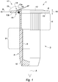
- the insert 1 comprises a body 3 having a shank 4 and a flange 5.
- the body 3 is in one piece.
- the shaft 4 extends along a longitudinal axis A and has a crimping section 6 configured to deform into a crimping bead 7, illustrated in FIG. figure 2 .
- the crimping bead 7 crimps the insert 1 on the support 2.
- the barrel 4 has a generally cylindrical shape.
- the term "cylinder” is here understood to mean a solid bounded by a cylindrical surface generated by a line, referred to as a generator, running through a closed planar curve, denoted as a director, and two planes intersecting the generatrices.
- the cylindrical surface of the barrel 4 may have one or more faces, so as to have a section whose outer edge is polygonal, for example hexagonal or square.
- the cylindrical surface of the barrel 4 may have a section whose outer edge is oblong, for example elliptical.
- the body 3 is in the form of a hollow cylinder delimiting a through or blind orifice 7 at a distal end of the barrel 4.
- the barrel 4 may further comprise a threaded section 8 adjacent to the crimping section 6.
- the threaded section 8 has an internal thread 9 for receiving a threaded piece to be aimed at the insert 1.
- the insert 1 thus comprises, in the order in a direction of the longitudinal axis A, the flange 5, the crimping section 6, the threaded portion 8 and a distal end 10 of the barrel 4.
- the flange 5 is intended to come into contact with a receiving surface 11 of the support 2 when the insert 1 is crimped to the support 2.
- the flange 5 extends along a transverse axis B.
- the transverse axis B is perpendicular to the longitudinal axis A.
- the flange 5 has a proximal surface 12 and a distal surface 13 opposite the proximal surface 12.
- the proximal surface 12 is oriented in a direction opposite to the direction of the longitudinal axis A of the barrel 4.
- the distal surface 13 is oriented in the direction of the longitudinal axis A. In other words, the distal surface 13 is directed towards the crimping portion 6.
- the collar 5 has a fold 14 forming a groove 15 located on the distal surface 13.
- the groove 15 is intended to receive a seal 16.
- the seal 16 provides a seal a fixing assembly comprising the support 2, the insert 1 and the seal 16.
- the seal 16 provides a seal to fluids, such as water, oil, glycol, and more usually to gases, like air.
- the seal 16 is intended to be interposed between the receiving surface 11 of the support 2 and the distal surface 13.
- the seal 16 is made of a material different from that of the insert 1.
- the seal 16 is made of a deformable material, for example plastic or elastomeric material, for example natural or synthetic rubbers.
- the seal 16 has a generally toric shape.
- the seal 16 may be mounted on the insert 1 to form a fastening element 17.
- the fold 14 of the flange 5 allows the flange 5 to be in contact with the receiving surface 11 of the support 2 when the insert 1 is crimped to the support 2.
- the distal surface 13 comprises a first part 13a on which the groove 15 is located, and a second part 13b located at one end of the collar 5 opposite the barrel 4.
- the flange 5 has another opposite end in contact with the barrel 4.
- the groove 15 is located between the 4 and the second portion 13b of the distal surface 13.
- the groove 15 accommodates the seal 16 while maintaining contact between the two facing surfaces 13b, 11 and prevents the phenomenon of lifting the flange 5 due to the spring effect of the seal 16 when the latter is compressed during crimping. So we improves the mechanical strength of the insert 1 while ensuring an effective seal.
- the flange 5 has a constant thickness 18.
- the groove 15 can be made by folding the collar 5.
- the folding also forms the fold 14.
- the collar 5 is deformed to form the fold 14 at an angle 19 determined relative to the transverse axis B.
- the folding can be achieved by compressing the flange 5 along the transverse axis B. It can also be used a matrix placed opposite the distal surface to promote the formation of the groove 15 during folding. Thanks to folding, it is possible to make the groove 15 without using a particular striking step of the flange 5.
- constant thickness of the flange 5 is meant a thickness whose value is maintained along the transverse axis B.
- a first flange portion 5 joining the barrel 4 to the ply 14 has the same thickness as a second flange portion 5 joining the ply 14 to the end of the flange 5 opposite the barrel 4.
- a suitable matrix may, when folding and using a suitable matrix, create radial folds located on the distal surface 13 extending from the barrel 4 to the opposite end of the collar 5. These radial folds make it possible to stiffen the collar 5 while maintaining a constant thickness along the transverse axis B.
- Such folding is particularly suitable when the flange 5 has a small thickness.
- low thickness is meant a thickness 18 greater than or equal to 0.5 mm and strictly less than 2 mm.
- the thickness 18 is strictly less than 1.5 mm.
- the striking tool when forming a groove by striking a flange having a small thickness, the striking tool can break because it is not suitable for small thicknesses. Indeed, the stresses generated by the striking tool intended for high thicknesses may be greater than the breaking strength of the tool because the thickness of the flange is small and does not sufficiently absorb the energy generated by deformation. such constraints.
- the insert 1 is crimped, that is to say it is mounted on the support 2 by a crimping operation.
- Crimping consists of deforming the insert 1, by traction or by pressing, for example in press, at the distal end of the barrel 4, to form the crimping bead 7 which comes into contact with the support 2 in order to wedge the support 2 between the flange 5 of the insert 1 and the bead crimping device 7, which makes it possible to fix the insert 1 to the support 2. More particularly, the crimping bead 7 comes into contact with a surface 20 of the support 2 opposite to the receiving surface 11.
- an attachment assembly 21 comprising the support 2 and the fastening element 17 crimped on the support 2.
- an orifice is previously formed in the support 2 to introduce the insert 1 to crimp.
- the support 2 has a thickness 22 of between 0.5 and 8 mm inclusive.
- the method further comprises a step of folding the flange so as to maintain a constant thickness of the flange and to form a groove on the surface.
- the method of manufacturing the fastening element 17 comprises a step of housing a seal 16 within the groove 15 of the insert 1.
- the method of manufacturing the fastening assembly 21 comprises a step of crimping the fastening element 21 on the support 2.
Landscapes
- Engineering & Computer Science (AREA)
- General Engineering & Computer Science (AREA)
- Mechanical Engineering (AREA)
- Connection Of Plates (AREA)
- Gasket Seals (AREA)
- Insertion Pins And Rivets (AREA)
- Clamps And Clips (AREA)
- Snaps, Bayonet Connections, Set Pins, And Snap Rings (AREA)
- Automotive Seat Belt Assembly (AREA)
Applications Claiming Priority (1)
| Application Number | Priority Date | Filing Date | Title |
|---|---|---|---|
| FR1751385A FR3063121B1 (fr) | 2017-02-22 | 2017-02-22 | Insert a sertir, element et ensemble de fixation comprenant un tel insert et procedes de fabrication de telles pieces. |
Publications (2)
| Publication Number | Publication Date |
|---|---|
| EP3366932A1 true EP3366932A1 (de) | 2018-08-29 |
| EP3366932B1 EP3366932B1 (de) | 2021-10-27 |
Family
ID=58707771
Family Applications (1)
| Application Number | Title | Priority Date | Filing Date |
|---|---|---|---|
| EP18157053.2A Active EP3366932B1 (de) | 2017-02-22 | 2018-02-16 | Einsatz zum crimpen, befestigungselement und -einheit, die einen solchen einsatz umfassen, und herstellungsverfahren von solchen teilen |
Country Status (4)
| Country | Link |
|---|---|
| US (1) | US10920813B2 (de) |
| EP (1) | EP3366932B1 (de) |
| CN (1) | CN108457969A (de) |
| FR (1) | FR3063121B1 (de) |
Cited By (2)
| Publication number | Priority date | Publication date | Assignee | Title |
|---|---|---|---|---|
| EP3885589A1 (de) * | 2020-03-25 | 2021-09-29 | Bollhoff Otalu S.A. | Blindnieteinsatz, bauteil mit eingebautem blindnieteinsatz und verfahren zum einbau eines solchen blindnieteinsatzes in eine bauteilöffnung |
| FR3153008A1 (fr) * | 2023-09-20 | 2025-03-21 | Safran Aircraft Engines | Insert désaxé à sertir et son procédé de sertissage |
Families Citing this family (7)
| Publication number | Priority date | Publication date | Assignee | Title |
|---|---|---|---|---|
| ES2985140T3 (es) * | 2017-11-27 | 2024-11-04 | Sps Tech Llc | Elemento de fijación ciego de dos piezas |
| CN109780037B (zh) * | 2019-03-08 | 2024-04-30 | 宾科精密部件(中国)有限公司 | 一种铆接系统的防水连接件及铆接系统 |
| CN109780038B (zh) * | 2019-03-08 | 2024-07-16 | 宾科精密部件(中国)有限公司 | 铆接系统的防水连接件及铆接系统 |
| EP3969766B1 (de) * | 2019-05-14 | 2024-10-16 | Topaz Trading Pty Ltd | Gewindebolzenpaar, pfostenverankerungssystem und verfahren zum befestigen eines pfostens an einem pfostenanker |
| CA3145831A1 (en) | 2019-07-05 | 2021-01-14 | Topaz Trading Pty Ltd | Post support and related methods |
| CN111894956A (zh) * | 2020-07-15 | 2020-11-06 | 常金华 | 一种高强度密封拉铆钉 |
| US11441588B1 (en) * | 2021-03-31 | 2022-09-13 | Bright Power Inc. | Equipment mounting systems and processes thereof |
Citations (5)
| Publication number | Priority date | Publication date | Assignee | Title |
|---|---|---|---|---|
| DE2700665A1 (de) * | 1976-01-30 | 1977-08-04 | Textron Inc | Befestiger-satz zum verbinden einer zusammengesetzten platte o.dgl. mit einem rahmenabschnitt |
| US6283691B1 (en) * | 1998-01-27 | 2001-09-04 | B & B Hardware, Inc. | Headed fastener with precisely calculated groove under head to accomodate o'ring sealing member as a self-sealing assembly |
| US20050019129A1 (en) * | 2003-07-22 | 2005-01-27 | Wolfgang Hesse | Joining assembly for joining a pair of structural members |
| EP1557577A2 (de) * | 2004-01-21 | 2005-07-27 | Newfrey LLC | Blindnietmutter |
| EP1953398A1 (de) * | 2007-02-05 | 2008-08-06 | Honsel Umformtechnik GmbH | Blindnietmutter oder -gewindebolzen |
Family Cites Families (26)
| Publication number | Priority date | Publication date | Assignee | Title |
|---|---|---|---|---|
| FR1080808A (fr) * | 1952-05-17 | 1954-12-14 | Goodrich Co B F | Perfectionnements apportés aux rivets tubulaires et aux procédés et dispositifs pour fabriquer ces rivets |
| FR1444261A (fr) * | 1965-05-21 | 1966-07-01 | Textron Ind Inc | Perfectionnements aux rivets borgnes et procédé de pose de ces rivets |
| US4170920A (en) * | 1975-11-17 | 1979-10-16 | Olympic Fastening Systems, Inc. | Blind spacer fastener |
| CA1061614A (en) * | 1975-11-17 | 1979-09-04 | George Siebol | Blind spacer fastener |
| US4170919A (en) * | 1975-11-17 | 1979-10-16 | Olympic Fastening Systems, Inc. | Blind spacer fastener |
| US4182216A (en) * | 1978-03-02 | 1980-01-08 | Textron, Inc. | Collapsible threaded insert device for plastic workpieces |
| GB2120741A (en) * | 1982-05-21 | 1983-12-07 | Avdel Ltd | Blind rivets |
| GB2136075B (en) * | 1983-03-07 | 1986-11-05 | Avdel Ltd | Rivet |
| GB2163823A (en) | 1984-08-31 | 1986-03-05 | Avdel Ltd | Self-plugging blind rivet |
| DE3513644A1 (de) * | 1985-04-16 | 1986-10-16 | Ludwig 8761 Mönchberg Kraemer | Nietmutter |
| DE4019193A1 (de) * | 1990-06-15 | 1991-12-19 | Audi Ag | Blindniet und verwendung des blindniets |
| DE9304575U1 (de) * | 1992-09-23 | 1993-05-27 | Gesellschaft für Befestigungstechnik Gebr. Titgemeyer GmbH & Co. KG, 4500 Osnabrück | Nietverbindung |
| BE1007284A3 (nl) * | 1993-07-12 | 1995-05-09 | Dejond Naamloze Vennootschap E | Blindklinkbout. |
| GB2368107B (en) | 2000-10-19 | 2004-01-21 | Textron Fastening Syst Ltd | Blind fastener |
| CN1590785A (zh) * | 2003-08-29 | 2005-03-09 | 章敏 | 铆接螺母 |
| DE102004003240A1 (de) * | 2004-01-21 | 2005-08-11 | Newfrey Llc, Newark | Blindnietmutter |
| EP1918596B1 (de) * | 2006-11-03 | 2012-03-21 | Herbert Schruff | Blindnietelement sowie Verwendung hierfür |
| CN201588861U (zh) * | 2009-11-09 | 2010-09-22 | 宁波市镇海合鑫标准件有限公司 | 铆接螺母 |
| CN202284593U (zh) * | 2011-10-24 | 2012-06-27 | 湖南省金为型材有限公司 | 防水抽芯铆钉 |
| EP2594813B1 (de) * | 2011-11-21 | 2015-06-17 | Dregischan, Simone | Blindnietelement |
| DE102012016592A1 (de) * | 2012-08-16 | 2014-02-20 | Newfrey Llc | Blindnietanordnung |
| JP6349609B2 (ja) * | 2014-05-22 | 2018-07-04 | ポップリベット・ファスナー株式会社 | ブラインドナット |
| FR3042829B1 (fr) * | 2015-10-27 | 2018-03-09 | A Raymond Et Cie | Rivet auto-perceur a haute resistance mecanique |
| CN205744777U (zh) * | 2016-06-17 | 2016-11-30 | 江苏省艾维德紧固件有限公司 | 一种防水拉丝铆钉 |
| CN105909655A (zh) * | 2016-06-21 | 2016-08-31 | 无锡安欣达科技有限公司 | 一种复合可卸式台阶铆接螺母 |
| EP3263921B1 (de) * | 2016-07-01 | 2019-11-06 | Ford Global Technologies, LLC | Blindnietmutter, befestigungsanordnung mit einer blindnietmutter und befestigungsverfahren |
-
2017
- 2017-02-22 FR FR1751385A patent/FR3063121B1/fr active Active
-
2018
- 2018-02-02 US US15/887,100 patent/US10920813B2/en active Active
- 2018-02-09 CN CN201810133145.7A patent/CN108457969A/zh active Pending
- 2018-02-16 EP EP18157053.2A patent/EP3366932B1/de active Active
Patent Citations (5)
| Publication number | Priority date | Publication date | Assignee | Title |
|---|---|---|---|---|
| DE2700665A1 (de) * | 1976-01-30 | 1977-08-04 | Textron Inc | Befestiger-satz zum verbinden einer zusammengesetzten platte o.dgl. mit einem rahmenabschnitt |
| US6283691B1 (en) * | 1998-01-27 | 2001-09-04 | B & B Hardware, Inc. | Headed fastener with precisely calculated groove under head to accomodate o'ring sealing member as a self-sealing assembly |
| US20050019129A1 (en) * | 2003-07-22 | 2005-01-27 | Wolfgang Hesse | Joining assembly for joining a pair of structural members |
| EP1557577A2 (de) * | 2004-01-21 | 2005-07-27 | Newfrey LLC | Blindnietmutter |
| EP1953398A1 (de) * | 2007-02-05 | 2008-08-06 | Honsel Umformtechnik GmbH | Blindnietmutter oder -gewindebolzen |
Cited By (6)
| Publication number | Priority date | Publication date | Assignee | Title |
|---|---|---|---|---|
| EP3885589A1 (de) * | 2020-03-25 | 2021-09-29 | Bollhoff Otalu S.A. | Blindnieteinsatz, bauteil mit eingebautem blindnieteinsatz und verfahren zum einbau eines solchen blindnieteinsatzes in eine bauteilöffnung |
| WO2021190951A1 (en) | 2020-03-25 | 2021-09-30 | Bollhoff Otalu S.A. | Blind rivet insert, a component with an installed blind rivet insert and method for installing such a blind rivet insert in a component opening |
| JP2022547743A (ja) * | 2020-03-25 | 2022-11-15 | ベルホフ オタル エス.エー | ブラインドリベットインサート、ブラインドリベットインサートが装着された部材およびこのようなブラインドリベットインサートを部材開口部内に装着する方法 |
| JP7198390B2 (ja) | 2020-03-25 | 2022-12-28 | ベルホフ オタル エス.エー | ブラインドリベットインサート、ブラインドリベットインサートが装着された部材およびこのようなブラインドリベットインサートを部材開口部内に装着する方法 |
| US11686338B2 (en) | 2020-03-25 | 2023-06-27 | Bollhoff Otalu S.A. | Blind rivet insert, a component with an installed blind rivet insert and method for installing such a blind rivet insert in a component opening |
| FR3153008A1 (fr) * | 2023-09-20 | 2025-03-21 | Safran Aircraft Engines | Insert désaxé à sertir et son procédé de sertissage |
Also Published As
| Publication number | Publication date |
|---|---|
| US10920813B2 (en) | 2021-02-16 |
| US20180238369A1 (en) | 2018-08-23 |
| FR3063121A1 (fr) | 2018-08-24 |
| EP3366932B1 (de) | 2021-10-27 |
| CN108457969A (zh) | 2018-08-28 |
| FR3063121B1 (fr) | 2019-03-29 |
Similar Documents
| Publication | Publication Date | Title |
|---|---|---|
| EP3366932B1 (de) | Einsatz zum crimpen, befestigungselement und -einheit, die einen solchen einsatz umfassen, und herstellungsverfahren von solchen teilen | |
| EP2265828B1 (de) | Montageverfahren für verbundwerkstoffe und nietelement zu seiner durchführung | |
| EP2917969B1 (de) | Vorrichtung zum fixieren einer elektrischen anschlussklemme an einem träger | |
| EP3553331B1 (de) | Verbindungsvorrichtung, die zwischen mindestens zwei teilen schwenkbar ist, luftfahrzeug, das eine abdeckung umfasst, die mit dieser schwenkbaren verbindungsvorrichtung ausgestattet ist | |
| EP2960531B1 (de) | Werkstück zum festklemmen auf einer halterung, vorrichtung, die ein solches werkstück umfasst, und herstellungsverfahren eines solchen werkstücks und einer solchen vorrichtung | |
| FR2491562A1 (fr) | Rivet en deux parties | |
| FR2995372A1 (fr) | Dispositif de fixation | |
| EP2552622B1 (de) | Niet und nietsetzvorrichtung | |
| EP3030797B1 (de) | Strukturbefestigungsvorrichtung | |
| EP2344775B1 (de) | Blindbefestigungsvorrichtung | |
| EP1941167B1 (de) | Blindniet und verfahren zu dessen entfernung | |
| EP2549592B1 (de) | Spitzeneinsatz und Vorrichtung, die einen solchen Einsatz umsetzt | |
| FR3017429A1 (fr) | Ecrou a sertir en aveugle sur un support | |
| FR2945088A1 (fr) | Systeme d'ecrou noye a sertir en aveugle avec axe ajustable | |
| FR3117049A1 (fr) | Procédé de pose d’une fixation au travers d’un assemblage de pièces structurales avec fluage d’un mastic interposé | |
| EP3199405A1 (de) | Dachlastenträger für kraftfahrzeug, und entsprechendes befestigungssystem | |
| EP1958715A1 (de) | Verfahren zum Zusammenbau von mindestens zwei Elementen mit Hilfe eines Blindniets | |
| FR2979401A1 (fr) | Dispositif a sertir pour fixer un element en plastique, et installation mettant en oeuvre ledit dispositif | |
| EP0382638B1 (de) | Blindnietmutter und das Einsetzen in irgendeine Wand | |
| EP3061979B1 (de) | Einsatz zum bördeln eines werkstücks, das auf einer halterung befestigt werden soll, und einen solchen einsatz umfassende befestigungseinheit | |
| EP1598567B1 (de) | Verfahren zum Zusammenbau einer Pressniete und Pressniete hergestellt durch ein solches Verfahren | |
| EP2497965B1 (de) | Befestigungsvorrichtung, die mit einem mobilen Klemmelement zum Anpressen gegen eine Mutter der Vorrichtung ausgestattet ist, und Festklemmverfahren der Vorrichtung | |
| FR3024507A1 (fr) | Goujon a sertir dans un support | |
| WO2025153782A1 (fr) | Element de jonction assurant un assemblage multi-materiaux de trois epaisseurs | |
| EP4174330A1 (de) | Verfahren und befestigung zum zusammenbau mindestens zweier elementarer bauteile |
Legal Events
| Date | Code | Title | Description |
|---|---|---|---|
| PUAI | Public reference made under article 153(3) epc to a published international application that has entered the european phase |
Free format text: ORIGINAL CODE: 0009012 |
|
| STAA | Information on the status of an ep patent application or granted ep patent |
Free format text: STATUS: THE APPLICATION HAS BEEN PUBLISHED |
|
| AK | Designated contracting states |
Kind code of ref document: A1 Designated state(s): AL AT BE BG CH CY CZ DE DK EE ES FI FR GB GR HR HU IE IS IT LI LT LU LV MC MK MT NL NO PL PT RO RS SE SI SK SM TR |
|
| AX | Request for extension of the european patent |
Extension state: BA ME |
|
| STAA | Information on the status of an ep patent application or granted ep patent |
Free format text: STATUS: REQUEST FOR EXAMINATION WAS MADE |
|
| 17P | Request for examination filed |
Effective date: 20190524 |
|
| RBV | Designated contracting states (corrected) |
Designated state(s): AL AT BE BG CH CY CZ DE DK EE ES FI FR GB GR HR HU IE IS IT LI LT LU LV MC MK MT NL NO PL PT RO RS SE SI SK SM TR |
|
| STAA | Information on the status of an ep patent application or granted ep patent |
Free format text: STATUS: EXAMINATION IS IN PROGRESS |
|
| 17Q | First examination report despatched |
Effective date: 20200618 |
|
| GRAP | Despatch of communication of intention to grant a patent |
Free format text: ORIGINAL CODE: EPIDOSNIGR1 |
|
| STAA | Information on the status of an ep patent application or granted ep patent |
Free format text: STATUS: GRANT OF PATENT IS INTENDED |
|
| INTG | Intention to grant announced |
Effective date: 20210302 |
|
| RIN1 | Information on inventor provided before grant (corrected) |
Inventor name: BEGEL, NICOLAS Inventor name: PERROUD, NORBERT |
|
| GRAJ | Information related to disapproval of communication of intention to grant by the applicant or resumption of examination proceedings by the epo deleted |
Free format text: ORIGINAL CODE: EPIDOSDIGR1 |
|
| RAP3 | Party data changed (applicant data changed or rights of an application transferred) |
Owner name: BOLLHOFF OTALU |
|
| STAA | Information on the status of an ep patent application or granted ep patent |
Free format text: STATUS: EXAMINATION IS IN PROGRESS |
|
| GRAS | Grant fee paid |
Free format text: ORIGINAL CODE: EPIDOSNIGR3 |
|
| STAA | Information on the status of an ep patent application or granted ep patent |
Free format text: STATUS: GRANT OF PATENT IS INTENDED |
|
| GRAP | Despatch of communication of intention to grant a patent |
Free format text: ORIGINAL CODE: EPIDOSNIGR1 |
|
| INTC | Intention to grant announced (deleted) | ||
| INTG | Intention to grant announced |
Effective date: 20210707 |
|
| GRAA | (expected) grant |
Free format text: ORIGINAL CODE: 0009210 |
|
| STAA | Information on the status of an ep patent application or granted ep patent |
Free format text: STATUS: THE PATENT HAS BEEN GRANTED |
|
| AK | Designated contracting states |
Kind code of ref document: B1 Designated state(s): AL AT BE BG CH CY CZ DE DK EE ES FI FR GB GR HR HU IE IS IT LI LT LU LV MC MK MT NL NO PL PT RO RS SE SI SK SM TR |
|
| REG | Reference to a national code |
Ref country code: GB Ref legal event code: FG4D Free format text: NOT ENGLISH |
|
| REG | Reference to a national code |
Ref country code: CH Ref legal event code: EP |
|
| REG | Reference to a national code |
Ref country code: AT Ref legal event code: REF Ref document number: 1442050 Country of ref document: AT Kind code of ref document: T Effective date: 20211115 |
|
| REG | Reference to a national code |
Ref country code: DE Ref legal event code: R096 Ref document number: 602018025522 Country of ref document: DE |
|
| REG | Reference to a national code |
Ref country code: IE Ref legal event code: FG4D Free format text: LANGUAGE OF EP DOCUMENT: FRENCH |
|
| REG | Reference to a national code |
Ref country code: LT Ref legal event code: MG9D |
|
| REG | Reference to a national code |
Ref country code: NL Ref legal event code: MP Effective date: 20211027 |
|
| REG | Reference to a national code |
Ref country code: AT Ref legal event code: MK05 Ref document number: 1442050 Country of ref document: AT Kind code of ref document: T Effective date: 20211027 |
|
| PG25 | Lapsed in a contracting state [announced via postgrant information from national office to epo] |
Ref country code: RS Free format text: LAPSE BECAUSE OF FAILURE TO SUBMIT A TRANSLATION OF THE DESCRIPTION OR TO PAY THE FEE WITHIN THE PRESCRIBED TIME-LIMIT Effective date: 20211027 Ref country code: LT Free format text: LAPSE BECAUSE OF FAILURE TO SUBMIT A TRANSLATION OF THE DESCRIPTION OR TO PAY THE FEE WITHIN THE PRESCRIBED TIME-LIMIT Effective date: 20211027 Ref country code: FI Free format text: LAPSE BECAUSE OF FAILURE TO SUBMIT A TRANSLATION OF THE DESCRIPTION OR TO PAY THE FEE WITHIN THE PRESCRIBED TIME-LIMIT Effective date: 20211027 Ref country code: BG Free format text: LAPSE BECAUSE OF FAILURE TO SUBMIT A TRANSLATION OF THE DESCRIPTION OR TO PAY THE FEE WITHIN THE PRESCRIBED TIME-LIMIT Effective date: 20220127 Ref country code: AT Free format text: LAPSE BECAUSE OF FAILURE TO SUBMIT A TRANSLATION OF THE DESCRIPTION OR TO PAY THE FEE WITHIN THE PRESCRIBED TIME-LIMIT Effective date: 20211027 |
|
| PG25 | Lapsed in a contracting state [announced via postgrant information from national office to epo] |
Ref country code: IS Free format text: LAPSE BECAUSE OF FAILURE TO SUBMIT A TRANSLATION OF THE DESCRIPTION OR TO PAY THE FEE WITHIN THE PRESCRIBED TIME-LIMIT Effective date: 20220227 Ref country code: SE Free format text: LAPSE BECAUSE OF FAILURE TO SUBMIT A TRANSLATION OF THE DESCRIPTION OR TO PAY THE FEE WITHIN THE PRESCRIBED TIME-LIMIT Effective date: 20211027 Ref country code: PT Free format text: LAPSE BECAUSE OF FAILURE TO SUBMIT A TRANSLATION OF THE DESCRIPTION OR TO PAY THE FEE WITHIN THE PRESCRIBED TIME-LIMIT Effective date: 20220228 Ref country code: PL Free format text: LAPSE BECAUSE OF FAILURE TO SUBMIT A TRANSLATION OF THE DESCRIPTION OR TO PAY THE FEE WITHIN THE PRESCRIBED TIME-LIMIT Effective date: 20211027 Ref country code: NO Free format text: LAPSE BECAUSE OF FAILURE TO SUBMIT A TRANSLATION OF THE DESCRIPTION OR TO PAY THE FEE WITHIN THE PRESCRIBED TIME-LIMIT Effective date: 20220127 Ref country code: NL Free format text: LAPSE BECAUSE OF FAILURE TO SUBMIT A TRANSLATION OF THE DESCRIPTION OR TO PAY THE FEE WITHIN THE PRESCRIBED TIME-LIMIT Effective date: 20211027 Ref country code: LV Free format text: LAPSE BECAUSE OF FAILURE TO SUBMIT A TRANSLATION OF THE DESCRIPTION OR TO PAY THE FEE WITHIN THE PRESCRIBED TIME-LIMIT Effective date: 20211027 Ref country code: HR Free format text: LAPSE BECAUSE OF FAILURE TO SUBMIT A TRANSLATION OF THE DESCRIPTION OR TO PAY THE FEE WITHIN THE PRESCRIBED TIME-LIMIT Effective date: 20211027 Ref country code: GR Free format text: LAPSE BECAUSE OF FAILURE TO SUBMIT A TRANSLATION OF THE DESCRIPTION OR TO PAY THE FEE WITHIN THE PRESCRIBED TIME-LIMIT Effective date: 20220128 Ref country code: ES Free format text: LAPSE BECAUSE OF FAILURE TO SUBMIT A TRANSLATION OF THE DESCRIPTION OR TO PAY THE FEE WITHIN THE PRESCRIBED TIME-LIMIT Effective date: 20211027 |
|
| REG | Reference to a national code |
Ref country code: DE Ref legal event code: R026 Ref document number: 602018025522 Country of ref document: DE |
|
| PLBI | Opposition filed |
Free format text: ORIGINAL CODE: 0009260 |
|
| PG25 | Lapsed in a contracting state [announced via postgrant information from national office to epo] |
Ref country code: SM Free format text: LAPSE BECAUSE OF FAILURE TO SUBMIT A TRANSLATION OF THE DESCRIPTION OR TO PAY THE FEE WITHIN THE PRESCRIBED TIME-LIMIT Effective date: 20211027 Ref country code: SK Free format text: LAPSE BECAUSE OF FAILURE TO SUBMIT A TRANSLATION OF THE DESCRIPTION OR TO PAY THE FEE WITHIN THE PRESCRIBED TIME-LIMIT Effective date: 20211027 Ref country code: RO Free format text: LAPSE BECAUSE OF FAILURE TO SUBMIT A TRANSLATION OF THE DESCRIPTION OR TO PAY THE FEE WITHIN THE PRESCRIBED TIME-LIMIT Effective date: 20211027 Ref country code: EE Free format text: LAPSE BECAUSE OF FAILURE TO SUBMIT A TRANSLATION OF THE DESCRIPTION OR TO PAY THE FEE WITHIN THE PRESCRIBED TIME-LIMIT Effective date: 20211027 Ref country code: DK Free format text: LAPSE BECAUSE OF FAILURE TO SUBMIT A TRANSLATION OF THE DESCRIPTION OR TO PAY THE FEE WITHIN THE PRESCRIBED TIME-LIMIT Effective date: 20211027 Ref country code: CZ Free format text: LAPSE BECAUSE OF FAILURE TO SUBMIT A TRANSLATION OF THE DESCRIPTION OR TO PAY THE FEE WITHIN THE PRESCRIBED TIME-LIMIT Effective date: 20211027 |
|
| PLAB | Opposition data, opponent's data or that of the opponent's representative modified |
Free format text: ORIGINAL CODE: 0009299OPPO |
|
| PLAX | Notice of opposition and request to file observation + time limit sent |
Free format text: ORIGINAL CODE: EPIDOSNOBS2 |
|
| 26 | Opposition filed |
Opponent name: AVDEL UK LIMITED Effective date: 20220720 |
|
| R26 | Opposition filed (corrected) |
Opponent name: AVDEL UK LIMITED Effective date: 20220720 |
|
| PG25 | Lapsed in a contracting state [announced via postgrant information from national office to epo] |
Ref country code: MC Free format text: LAPSE BECAUSE OF FAILURE TO SUBMIT A TRANSLATION OF THE DESCRIPTION OR TO PAY THE FEE WITHIN THE PRESCRIBED TIME-LIMIT Effective date: 20211027 |
|
| REG | Reference to a national code |
Ref country code: CH Ref legal event code: PL |
|
| REG | Reference to a national code |
Ref country code: BE Ref legal event code: MM Effective date: 20220228 |
|
| PG25 | Lapsed in a contracting state [announced via postgrant information from national office to epo] |
Ref country code: LU Free format text: LAPSE BECAUSE OF NON-PAYMENT OF DUE FEES Effective date: 20220216 Ref country code: AL Free format text: LAPSE BECAUSE OF FAILURE TO SUBMIT A TRANSLATION OF THE DESCRIPTION OR TO PAY THE FEE WITHIN THE PRESCRIBED TIME-LIMIT Effective date: 20211027 |
|
| PG25 | Lapsed in a contracting state [announced via postgrant information from national office to epo] |
Ref country code: SI Free format text: LAPSE BECAUSE OF FAILURE TO SUBMIT A TRANSLATION OF THE DESCRIPTION OR TO PAY THE FEE WITHIN THE PRESCRIBED TIME-LIMIT Effective date: 20211027 |
|
| PLBB | Reply of patent proprietor to notice(s) of opposition received |
Free format text: ORIGINAL CODE: EPIDOSNOBS3 |
|
| PG25 | Lapsed in a contracting state [announced via postgrant information from national office to epo] |
Ref country code: LI Free format text: LAPSE BECAUSE OF NON-PAYMENT OF DUE FEES Effective date: 20220228 Ref country code: IE Free format text: LAPSE BECAUSE OF NON-PAYMENT OF DUE FEES Effective date: 20220216 Ref country code: CH Free format text: LAPSE BECAUSE OF NON-PAYMENT OF DUE FEES Effective date: 20220228 |
|
| PG25 | Lapsed in a contracting state [announced via postgrant information from national office to epo] |
Ref country code: BE Free format text: LAPSE BECAUSE OF NON-PAYMENT OF DUE FEES Effective date: 20220228 |
|
| PG25 | Lapsed in a contracting state [announced via postgrant information from national office to epo] |
Ref country code: IT Free format text: LAPSE BECAUSE OF FAILURE TO SUBMIT A TRANSLATION OF THE DESCRIPTION OR TO PAY THE FEE WITHIN THE PRESCRIBED TIME-LIMIT Effective date: 20211027 |
|
| PG25 | Lapsed in a contracting state [announced via postgrant information from national office to epo] |
Ref country code: HU Free format text: LAPSE BECAUSE OF FAILURE TO SUBMIT A TRANSLATION OF THE DESCRIPTION OR TO PAY THE FEE WITHIN THE PRESCRIBED TIME-LIMIT; INVALID AB INITIO Effective date: 20180216 |
|
| PG25 | Lapsed in a contracting state [announced via postgrant information from national office to epo] |
Ref country code: MK Free format text: LAPSE BECAUSE OF FAILURE TO SUBMIT A TRANSLATION OF THE DESCRIPTION OR TO PAY THE FEE WITHIN THE PRESCRIBED TIME-LIMIT Effective date: 20211027 Ref country code: CY Free format text: LAPSE BECAUSE OF FAILURE TO SUBMIT A TRANSLATION OF THE DESCRIPTION OR TO PAY THE FEE WITHIN THE PRESCRIBED TIME-LIMIT Effective date: 20211027 |
|
| PLAB | Opposition data, opponent's data or that of the opponent's representative modified |
Free format text: ORIGINAL CODE: 0009299OPPO |
|
| R26 | Opposition filed (corrected) |
Opponent name: AVDEL UK LIMITED Effective date: 20220720 |
|
| PG25 | Lapsed in a contracting state [announced via postgrant information from national office to epo] |
Ref country code: TR Free format text: LAPSE BECAUSE OF FAILURE TO SUBMIT A TRANSLATION OF THE DESCRIPTION OR TO PAY THE FEE WITHIN THE PRESCRIBED TIME-LIMIT Effective date: 20211027 |
|
| PG25 | Lapsed in a contracting state [announced via postgrant information from national office to epo] |
Ref country code: MT Free format text: LAPSE BECAUSE OF FAILURE TO SUBMIT A TRANSLATION OF THE DESCRIPTION OR TO PAY THE FEE WITHIN THE PRESCRIBED TIME-LIMIT Effective date: 20211027 |
|
| REG | Reference to a national code |
Ref country code: DE Ref legal event code: R100 Ref document number: 602018025522 Country of ref document: DE |
|
| PLCK | Communication despatched that opposition was rejected |
Free format text: ORIGINAL CODE: EPIDOSNREJ1 |
|
| PLBN | Opposition rejected |
Free format text: ORIGINAL CODE: 0009273 |
|
| STAA | Information on the status of an ep patent application or granted ep patent |
Free format text: STATUS: OPPOSITION REJECTED |
|
| 27O | Opposition rejected |
Effective date: 20241009 |
|
| PGFP | Annual fee paid to national office [announced via postgrant information from national office to epo] |
Ref country code: GB Payment date: 20260225 Year of fee payment: 9 |
|
| PGFP | Annual fee paid to national office [announced via postgrant information from national office to epo] |
Ref country code: DE Payment date: 20260226 Year of fee payment: 9 |
|
| PGFP | Annual fee paid to national office [announced via postgrant information from national office to epo] |
Ref country code: FR Payment date: 20260225 Year of fee payment: 9 |