EP3367015A1 - Climatiseur - Google Patents
Climatiseur Download PDFInfo
- Publication number
- EP3367015A1 EP3367015A1 EP16857180.0A EP16857180A EP3367015A1 EP 3367015 A1 EP3367015 A1 EP 3367015A1 EP 16857180 A EP16857180 A EP 16857180A EP 3367015 A1 EP3367015 A1 EP 3367015A1
- Authority
- EP
- European Patent Office
- Prior art keywords
- wind direction
- air conditioner
- direction plate
- air
- plate unit
- Prior art date
- Legal status (The legal status is an assumption and is not a legal conclusion. Google has not performed a legal analysis and makes no representation as to the accuracy of the status listed.)
- Withdrawn
Links
- 238000004891 communication Methods 0.000 claims description 5
- 239000000428 dust Substances 0.000 description 15
- 230000007246 mechanism Effects 0.000 description 13
- 238000001816 cooling Methods 0.000 description 9
- 238000010438 heat treatment Methods 0.000 description 9
- 238000003780 insertion Methods 0.000 description 8
- 230000037431 insertion Effects 0.000 description 8
- 238000004140 cleaning Methods 0.000 description 7
- 230000008859 change Effects 0.000 description 6
- 230000004308 accommodation Effects 0.000 description 5
- 230000001143 conditioned effect Effects 0.000 description 5
- 238000001514 detection method Methods 0.000 description 4
- 230000006872 improvement Effects 0.000 description 4
- 238000007664 blowing Methods 0.000 description 3
- 210000000078 claw Anatomy 0.000 description 3
- 238000003825 pressing Methods 0.000 description 3
- 230000036541 health Effects 0.000 description 2
- 238000009434 installation Methods 0.000 description 2
- 230000002093 peripheral effect Effects 0.000 description 2
- 239000004743 Polypropylene Substances 0.000 description 1
- 230000015556 catabolic process Effects 0.000 description 1
- 230000008878 coupling Effects 0.000 description 1
- 238000010168 coupling process Methods 0.000 description 1
- 238000005859 coupling reaction Methods 0.000 description 1
- 238000006731 degradation reaction Methods 0.000 description 1
- 230000000694 effects Effects 0.000 description 1
- 239000011159 matrix material Substances 0.000 description 1
- 239000002184 metal Substances 0.000 description 1
- 230000004048 modification Effects 0.000 description 1
- 238000012986 modification Methods 0.000 description 1
- -1 polypropylene Polymers 0.000 description 1
- 229920001155 polypropylene Polymers 0.000 description 1
- 238000005057 refrigeration Methods 0.000 description 1
- 229920005989 resin Polymers 0.000 description 1
- 239000011347 resin Substances 0.000 description 1
- 229910001220 stainless steel Inorganic materials 0.000 description 1
- 239000010935 stainless steel Substances 0.000 description 1
- 229920003002 synthetic resin Polymers 0.000 description 1
- 239000000057 synthetic resin Substances 0.000 description 1
- 238000011144 upstream manufacturing Methods 0.000 description 1
- 238000003466 welding Methods 0.000 description 1
Images


Classifications
-
- F—MECHANICAL ENGINEERING; LIGHTING; HEATING; WEAPONS; BLASTING
- F24—HEATING; RANGES; VENTILATING
- F24F—AIR-CONDITIONING; AIR-HUMIDIFICATION; VENTILATION; USE OF AIR CURRENTS FOR SCREENING
- F24F13/00—Details common to, or for air-conditioning, air-humidification, ventilation or use of air currents for screening
- F24F13/20—Casings or covers
-
- F—MECHANICAL ENGINEERING; LIGHTING; HEATING; WEAPONS; BLASTING
- F24—HEATING; RANGES; VENTILATING
- F24F—AIR-CONDITIONING; AIR-HUMIDIFICATION; VENTILATION; USE OF AIR CURRENTS FOR SCREENING
- F24F11/00—Control or safety arrangements
- F24F11/30—Control or safety arrangements for purposes related to the operation of the system, e.g. for safety or monitoring
- F24F11/49—Control or safety arrangements for purposes related to the operation of the system, e.g. for safety or monitoring ensuring correct operation, e.g. by trial operation or configuration checks
-
- F—MECHANICAL ENGINEERING; LIGHTING; HEATING; WEAPONS; BLASTING
- F24—HEATING; RANGES; VENTILATING
- F24F—AIR-CONDITIONING; AIR-HUMIDIFICATION; VENTILATION; USE OF AIR CURRENTS FOR SCREENING
- F24F13/00—Details common to, or for air-conditioning, air-humidification, ventilation or use of air currents for screening
- F24F13/08—Air-flow control members, e.g. louvres, grilles, flaps or guide plates
- F24F13/10—Air-flow control members, e.g. louvres, grilles, flaps or guide plates movable, e.g. dampers
- F24F13/14—Air-flow control members, e.g. louvres, grilles, flaps or guide plates movable, e.g. dampers built up of tilting members, e.g. louvre
- F24F13/15—Air-flow control members, e.g. louvres, grilles, flaps or guide plates movable, e.g. dampers built up of tilting members, e.g. louvre with parallel simultaneously tiltable lamellae
-
- F—MECHANICAL ENGINEERING; LIGHTING; HEATING; WEAPONS; BLASTING
- F24—HEATING; RANGES; VENTILATING
- F24F—AIR-CONDITIONING; AIR-HUMIDIFICATION; VENTILATION; USE OF AIR CURRENTS FOR SCREENING
- F24F2120/00—Control inputs relating to users or occupants
- F24F2120/10—Occupancy
- F24F2120/12—Position of occupants
Definitions
- the present invention relates to an air conditioner including a wind direction plate which changes the direction of air discharged from an outlet in the left-right direction.
- the conventional air conditioner includes a housing which has an inlet and an outlet for air, and which is attached to an upper part of a side wall of a room. Inside the housing, an air passage is formed to allow mutual communication between the inlet and the outlet. In the air passage, an air blower and a heat exchanger are disposed. On an upper wall of the air passage on a downstream side of the air blower, there is disposed a wind direction plate unit which is attachable and detachable.
- the wind direction plate unit has a base part, a plurality of vertical wind direction plates, a connection part, and an operation member.
- the base part has an engagement part which engages with the upper wall of the air passage.
- the vertical wind direction plates stand on the base part to be aligned with each other in the left-right direction, and rotatable in the left-right direction.
- the connection part connects the plurality of wind direction plates with each other.
- the operation member is disposed at a center part of the connection part in the left-right direction, and the user can rotate the wind direction plates in the left-right direction by operating the operation member.
- a plurality of lateral wind direction plates which are attachable and detachable with respect to the housing, are arranged parallel to each other in the up-down direction.
- the lateral wind direction plates are rotatable in the up-down direction to change the direction of air discharged from the outlet in the up-down direction.
- the user can detach the wind direction plate unit by removing the lateral wind direction plates, then releasing the engagement of the engagement part with the upper wall of the air passage, and then holding and pulling the wind direction plate unit downward. This allows the user easy cleaning of the wind direction plates, and further, easy cleaning of the air passage and the air blower via the outlet.
- Patent Document 1 Japanese Patent No. 3306250 (Page 4 , Page 5, FIG. 3 )
- the present invention aims to provide an air conditioner with improved user-friendliness.
- a blower includes a housing which has an inlet and an outlet for air, an air passage which is disposed in the housing to allow mutual communication between the inlet and the outlet, an air blower which is disposed in the air passage, and a wind direction plate unit which is attachable and detachable, and has a wind direction plate which changes a direction of air discharged from the outlet in a left-right direction.
- the wind direction plate unit includes a base part which is constituted by a downstream-side end part of a lower wall of the air passage, and a bottom wall part which constitutes a bottom wall of the housing.
- the wind direction plate unit in the air conditioner having the above configuration, it is preferable for the wind direction plate unit to be attached and detached by being moved to slide along a direction in which air is discharged from the outlet.
- the air conditioner having the above configuration further include a wind direction plate motor which is disposed inside the housing, and a connection part which is rotatably fitted to the base part, and connects a shaft of the wind direction plate motor to the wind direction plate.
- the connection part has a groove which is open at a rear end thereof such that the shaft is allowed to enter the groove through the rear end, and the connection part is supported by being loosely fitted in a through hole of the base part.
- both side walls of the groove in the air conditioner having the above configuration, it is preferable for both side walls of the groove to be inclined in directions such that the both side walls are more away from each other toward rear ends thereof.
- the through hole in the air conditioner having the above configuration, it is preferable for the through hole to be formed in an elliptical shape with a major axis thereof extending in the left-right direction.
- the air conditioner having the above configuration to further include an engagement part which is disposed in the housing, a movable member which is disposed between the bottom wall part and the base part of the wind direction plate unit, and which is biased by a biasing part into engagement with the engagement part, and a press member which is pressable via an opening formed in the bottom wall part.
- the press member when the press member is pressed, the movable member is caused to move to release the engagement of the movable member with the engagement part.
- the base part in the air conditioner having the above configuration, it is preferable for the base part to include an uneven part disposed on an outer surface thereof such that a position of the press member coincides with a position of the uneven part in the left-right direction.
- the air conditioner having the above configuration to further include an attachment/detachment detecting sensor which detects attachment and detachment of the wind direction plate unit.
- the air blower is prohibited from being driven when the wind direction plate unit has been detached.
- the attachment/detachment detecting sensor be a push button switch including a push button and an arm member disposed facing the push button, and that the wind direction plate unit be attached to the housing by being moved to slide on the arm member to cause the arm member to press the push button.
- the air conditioner having the above configuration to further include an occupancy sensor which detects a human body existing in a room.
- air is discharged from the outlet avoiding the human body by means of the wind direction plate.
- the air conditioner having the above configuration to further include an operation lever which is coupled to the occupancy sensor to change the direction of the occupancy sensor in the left-right direction, and a lid which is openable and closable, and covers the operation lever.
- a recess be disposed in a leading end of the operation lever, that a projection be disposed on the lid to be fitted in the recess, and that a direction of the occupancy sensor is variable between three directions by selectively holding one of the following three states: a first state where a right side surface of the operation lever inclined leftward is caught by the projection; a second state where the projection fits in the recess of the operation lever; and a third state where a left side surface of the operation lever inclined rightward is caught by the projection.
- an air conditioner includes a housing which has an inlet and an outlet for air, an air passage which is disposed in the housing to allow mutual communication between the inlet and the outlet, an air blower which is disposed in the air passage, an occupancy sensor which detects a human body existing in a room, and a wind direction plate which changes a direction of air discharged from the outlet in a left-right direction based on a result of detection performed by the occupancy sensor.
- the air conditioner further includes an operation lever which is coupled to the occupancy sensor and changes a direction of the occupancy sensor in the left-right direction, and a lid which is openable and closable, and covers the operation lever.
- a wind direction plate unit which is attachable and detachable and has a wind direction plate which changes a direction of air discharged from the outlet in a left-right direction, includes a base part constituted by a downstream-side end part of a lower wall of an air passage, and a bottom wall part which constitutes a bottom wall of the housing.
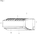
- FIG. 1 shows a perspective view of an air conditioner of a first embodiment.
- An air conditioner 1 which is installed on a wall inside a room, is an indoor unit connected to an outdoor unit (not shown) installed outdoors.
- the air conditioner 1 receives instructions, including those for starting operation and stopping operation, from a remote controller (not shown) operated by a user.
- the air conditioner 1 includes a housing 2 which is attached to a side wall W (see FIG. 2 ) inside a room, and a front panel 3, which constitutes a front face of the housing 2, is detachably attached with respect to the housing 2.
- the housing 2 engages a claw part (not shown) with, and thereby is supported on, an attachment plate (not shown), which is attached to the side wall W at a height close to a ceiling S (see FIG. 2 ).
- an inlet 4 is formed to extend in the left-right direction, and an outlet 5 is formed in a lower part of the housing 2.
- the outlet 5 has a substantially rectangular shape extending in the left-right direction of the housing 2, and faces downward.
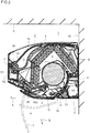
- FIG. 2 shows a side sectional view of the air conditioner 1.
- an air passage 6 is disposed which allows mutual communication between the inlet 4 and the outlet 5.
- an air blower 7 is disposed which blows out air. When the air blower 7 is driven, air in the room is drawn into the air passage 6 through the inlet 4, and is then blown out into the room through the outlet 5.
- a cross flow fan is preferably used, but other kinds of air blowers may be used instead.
- a heat exchanger 8 is disposed between the inlet 4 and the air blower 7 inside the air passage 6, a heat exchanger 8 is disposed.
- the heat exchanger 8 is connected to a compressor (not shown) disposed in the outdoor unit to operate a refrigeration cycle, and exchanges heat with air in the air passage 6.
- the wind guide panel 80 is opened, and cool air and warm air, respectively, are blown out into the room through the outlet 5.
- a drain pan 9 is disposed under the heat exchanger 8.
- a blow-out passage 63 is formed in the air passage 6, between the air blower 7 and the outlet 5, a blow-out passage 63 is formed.
- Upper and lower surfaces of the blow-out passage 63 are respectively constituted by an upper wall 63a and a lower wall 63b, and left and right surfaces of the blow-out passage 63 are constituted by side walls (not shown) on which a shaft of the air blower 7 is supported.
- the upper wall 63a and the lower wall 63b are both inclined downward toward their front ends, and guide air in a front downward direction.
- a wind direction plate unit 10 is disposed to be attachable and detachable with respect to the housing 2.
- the wind direction plate unit 10 includes a plurality of wind direction plates 12 which are rotatable in the left-right direction. Thereby, the direction of air discharged through the outlet 5 is changed in the left-right direction.
- a guide member (not shown) is disposed which guides the wind direction plate unit 10 to its fitting position. For attachment and detachment of the wind direction plate unit 10, the guide member guides the wind direction plate unit 10 to slide along a blowing-out direction of the outlet 5. A detailed description of the wind direction plate unit 10 will be given later.
- the wind guide panel 80 is supported, by an extendable arm member (not shown) disposed in the housing 2, to be rotatable in the up-down direction. As illustrated in FIG. 2 , the wind guide panel 80 closes the outlet 5 when the air conditioner 1 is not operating. Thereby, an inside of the air passage 6 becomes invisible, and as a result, the appearance of the air conditioner 1 is improved.
- the wind guide panel 80 rotates into a position indicated by an alternate long and short dash line X, and guides conditioned air discharged through the outlet 5 in a horizontal or upper direction, as indicated by an arrow A.
- the wind guide panel 80 rotates into a position indicated by an alternate long and two short dashes line Y, and guides conditioned air discharged through the outlet 5 in a downward direction as indicated by an arrow B.
- the direction of conditioned air discharged through the outlet 5 is changed in the up-down direction by the wind guide panel 80.
- a filter 70 is disposed which extends in the left-right direction and faces the inlet 4.
- the filter 70 is arranged from a front end part to a rear end part of the housing 2, and captures dust in the air drawn into the air passage 6 through the inlet 4.
- the filter 70 is formed by joining a polypropylene mesh (not shown), by welding, to a rectangular frame (not shown) which is formed of a synthetic resin such as ABS or the like and which has window parts arranged in a plurality of lines and columns.
- racks At left and right end parts of the frame of the filter 70, there are formed racks (not shown) which respectively mesh with pinions (not shown) disposed in the housing 2.
- a filter cleaner 50 is disposed which removes dust from the filter 70 and collects the removed dust.
- the filter cleaner 50 includes a filter motor (not shown), a rotary brush 51, a dust box 52, and a guide frame 53.
- the filter motor drives and rotates the pinions meshing with the racks of the filter 70.
- the guide frame 53 is disposed in an upper part of an inside of the housing 2, and guides the filter 70, which is caused to move when the filter motor is driven.
- the filter motor is driven, the filter 70 moves to and fro between a capture position C at which the filter 70 faces the inlet 4 and an inversion position D at which the filter 70 is turned upside down.
- the dust box 52 is disposed below the guide frame 53, and is attachable and detachable with respect to the housing 2.
- the rotary brush 51 is disposed over the dust box 52, and is driven to rotate by a brush motor (not shown). The rotary brush 51 removes dust from the filter 70 while the filter 70 is moving, and the removed dust is collected in the dust box 52.
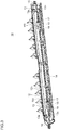
- FIG. 3 shows a perspective view of the wind direction plate unit 10, as seen from a rear face side.
- FIG. 4 shows a side sectional view of the wind direction plate unit 10, illustrating how the wind direction plate unit 10 is attached to the housing 2.
- FIG. 5 shows a top view of the wind direction plate unit 10.
- FIG. 6 shows a rear sectional view of the wind direction plate unit 10.
- the wind direction plate unit 10 includes a base part 11, a plurality of wind direction plates 12, a connection part 13, and a bottom wall part 14.
- the base part 11 is constituted by a downstream-side end part of the lower wall 63b of the air passage 6.
- an upper surface of the base part 11 is flush with an upper surface of such a part of the lower wall 63b as is on the upstream side of the base part 11.
- the through hole 11a is formed in a substantially elliptical shape which has a major axis thereof extending in the left-right direction, and cut parts 11g (see FIG. 11 ) are disposed one at each of left and right end parts of the through hole 11a.
- the plurality of wind direction plates 12 are stood on the base part 11 to be aligned with each other in the left-right direction, and are rotatable, in the left-right direction.
- the connection part 13 has an insertion part 13c (see FIG. 10 ) which has a groove 13a and is inserted in the through hole 11a, and a connection bar 13b which is connected to the insertion part 13c and couples the plurality of wind direction plates 12 to each other.
- a later-described cap 22 which is disposed on a shaft 21 of a wind direction plate motor 20, is fitted to be attachable and detachable.
- the insertion part 13c is substantially circular shaped in horizontal section, and has two engagement parts 13d (see FIG. 11 ) projecting from a circumferential surface of the insertion part 13c, and a flange 13e (see FIG.
- the engagement parts 13d are respectively inserted in the cut parts 11g, and then the insertion part 13c is turned. Thereby, the peripheral part of the through hole 11a is disposed between the engagement parts 13d and the flange 13e, and the insertion part 13c is rotatably supported at the base part 11 by being loosely fitted in the through hole 11a.
- the bottom wall part 14 is connected to a front end of the base part 11 (a terminal end of the lower wall 63b of the air passage 6), and constitutes a bottom wall of the housing 2. Further, in right and left parts of the wind direction plate unit 10, lock mechanisms 100 are disposed for locking the wind direction plate unit 10 onto the housing 2.
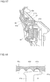
- FIG. 7 and FIG. 8 show rear sectional views of one of the lock mechanisms 100 that is disposed in the left part of the wind direction plate unit 10.
- FIG. 7 illustrates a locked state
- FIG. 8 illustrates an unlocked state.
- the right-side one of the lock mechanisms 100 has the same configuration as the left-side one, and thus the following description of the lock mechanisms 100 will be given by taking the left-side lock mechanism 100 as a representative example of the lock mechanisms 100.
- the lock mechanism 100 has an engagement part 16 (see FIG. 9 ), a biasing part 17, a movable member 18, and a press member 19.
- FIG. 9 shows a top sectional view of a left end part of a lower end part of the housing 2.
- the engagement part 16 is a recess formed in the left end part of the lower end part of the housing 2 to have an opening on a side face.
- Anterior to the engagement part 16, a slope 25 is disposed which is inclined such that a rearer part of the slope 25 is closer to a center part of the housing 2 in the left-right direction.
- the movable member 18 is disposed between the bottom wall part 14 and the base part 11 of the wind direction plate unit 10, and biased, by the biasing part 17 which is a coil spring or the like, in a direction toward engagement of a leading end part 18a of the movable member 18 with the engagement part 16.
- the biasing part 17 which is a coil spring or the like
- the press member 19 is pressable via an opening 14a formed in the bottom wall part 14.
- a leading end part 19a of the press member 19 slides on the slope 18 of the movable member 18 to cause the movable member 18 to move rightward (leftward in the figure).
- the leading end part 18a moves rightward such that the engagement between the leading end part 18a and the engagement part 16 is released, and the wind direction plate unit 10 is unlocked from the housing 2.
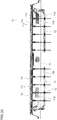
- FIG. 10 and FIG. 11 show a front sectional view and a bottom sectional view, respectively, of the insertion part 13c of the connection part 13.
- the wind direction plate motor 20 Behind a front end part of the lower wall 63b inside the housing 2, the wind direction plate motor 20 is disposed.
- the cap 22 To a leading end part of the shaft 21 of the wind direction plate motor 20, the cap 22 is fitted which is rectangular shaped in section.
- the groove 13a has a rear end thereof opened, such that the cap 22 is allowed to enter and exit the groove 13a via the open rear end. Thereby, it is easy to couple and uncouple the wind direction plate unit 10 to and from the shaft 21 of the wind direction plate motor 20.
- the connection part 13 is coupled to the shaft 21 to allow the rotation of the shaft 21 to be transferred to the wind direction plates 12.
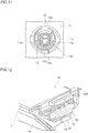
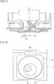
- FIG. 12 and FIG. 13 are a perspective sectional view and a top sectional view, respectively, of a right end part of the wind direction plate unit 10. Note that FIG. 12 and FIG. 13 show the wind direction plate unit 10 in a state where it is attached in the housing 2. At each of left and right end parts of the lower end part of the housing 2, an attachment/detachment detecting sensor 30 is disposed.
- the attachment/detachment detecting sensor 30 is a push-button switch, and includes a push button 31 and an arm member 32.
- the arm member 32 is made of a thin-rectangular shaped plate of a metal such as stainless steel or the like, and disposed, with a front end thereof as a fulcrum, so as to be biased in a direction away from the push button 31, and face the push button 31.
- a rear end of the arm member 32 is curved to be convex upward to form a curved part 32a.
- FIG. 14 shows a side view of the arm member 32 of the attachment/detachment detecting sensor 30.
- the projection 15 slides on the arm member 32 rearward from the front side. Then, when the projection 15 reaches a position indicated by an alternate long and short dash line 15', it moves onto the curved part 32a to push the arm member 32 down into a position indicated by an alternate long and short dash line 32'. Meanwhile, the push button 31 is pushed by the arm member 32 down into a position indicated by an alternate long and short dash line 31'.
- the air conditioner 1 thereby determines that the wind direction plate unit 10 has been attached to the housing 2.
- the pressing of the push button 31 by the projection 15 via the arm member 32 is released.
- the air conditioner 1 thereby determines that the wind direction plate unit 10 has been detached from the housing 2. At this time, driving of the air blower 7 is prohibited. This allows safe cleaning of the air blower 7 and the air passage 6 to be performed with the wind direction plate unit 10 detached.
- the above-configured air conditioner 1 starts the cooling or heating operation when the user operates the remote controller.
- the wind guide panel 80 rotates into a position indicated by the alternate long and short dash line X (see FIG. 2 ), such that conditioned air is discharged through the outlet 5 in the horizontal or upper direction, as indicated by the arrow A.
- the wind guide panel 80 rotates into a position indicated by the alternate long and two short dashes line Y (see FIG. 2 ), such that conditioned air is discharged downward through the outlet 5, as indicated by the arrow B.
- heating of the room is performed.
- the filter motor of the filter cleaner 50 is driven to cause the pinions to turn.
- the filter 70 is caused to move, along the guide frame 53, from the capture position C toward the inversion position D, and on reaching the inversion position D, the filter 70 moves toward the capture position C.
- the rotary brush 51 is caused to rotate by the brush motor, and dust on the filter 70 is removed by the rotary brush 51.
- the dust removed from the filter 70 is accumulated in the dust box 52.
- the dust box 52 is detachable from the housing 2 to dump the dust accumulated therein.
- the wind direction plates 12 are arranged to be perpendicular to a width direction (the left-right direction) of the housing 2 (a state illustrated in FIG. 5 ). In this state, a long side of the cap 22 of the wind direction plate motor 20 is perpendicular to the width direction of the housing 2. Further, the wind guide panel 80 is disposed in the position indicated by the alternate long and two short dashes line Y (see FIG. 2 ).
- the wind direction plate unit 10 includes the base part 11 which is constituted by the downstream-side end part of the lower wall 63b of the air passage 6, and the bottom wall part 14 constituting the bottom wall of the housing 2. Thereby, the user is allowed to easily detach the wind direction plate unit 10, without performing any detachment operation inside the air passage 6 far away from the outlet 5. This contributes to the improvement of user-friendliness of the air conditioner 1.
- the lock mechanism 100 since the lock mechanism 100 is disposed outside the air passage 6, the lock mechanism 100 does not interfere with the air flowing in the air passage 6. Accordingly, it is possible to prevent air flow disturbance which would otherwise be caused by the lock mechanism 100, and thus to prevent degradation of the blowing performance of the air conditioner 1.
- the user With the wind direction plate unit 10 detached, the user can easily reach the inside of the air passage 6 and the air blower 7 via the outlet 5 for cleaning. It is also easy for the user to clean the wind direction plates 12. This contributes to the improvement of the cleanability of the air conditioner 1.
- the air blower 7 since the air blower 7 is prohibited from being driven at this time, safe cleaning of the air blower 7 and the air passage 6 is ensured.
- the notification for prompting the user to attach the wind direction plate unit 10 may be given by lighting an indicator (not shown) disposed on the front face of the housing 2.
- the user After cleaning the air passage 6 and the air blower 7, the user attaches the wind direction plate unit 10 to the housing 2. At this time, the leading end part 18a of the movable member 18 is pressed against the slope 25 (see FIG. 9 ) of the housing 2, and thus moves against the biasing force of the biasing part 17 to reach the engagement part 16, and then the leading end part 18a engages with the engagement part 16. Thus, just by moving the wind direction plate unit 10 to slide along the blowing-out direction of the outlet 5 without pressing the press member 19, the leading end part 18a is brought into engagement with the engagement part 16, and the wind direction plate unit 10 is locked to the housing 2.
- the wind direction plate unit 10 which is attachable and detachable, and has the wind direction plates 12, includes the base part 11, which is constituted by the downstream-side end part of the lower wall of the air passage 6, and the bottom wall part 14, which constitutes the bottom wall of the housing 2.
- This configuration allows the user to easily detach the wind direction plate unit 10 without performing any detachment operation inside the air passage 6 away from the outlet 5. This contributes to the improvement of user-friendliness of the air conditioner 1.
- connection part 13 of the wind direction plate unit 10 has the groove 13a, which is open at a rear end thereof such that the shaft 21 of the wind direction plate motor 20 is allowed to enter the groove 13a through the rear end, and the connection part 13 is loosely fitted in the through hole 11a disposed in the base part 11.
- connection part 13 is supported by being loosely fitted in the through hole 11a, it is possible to allow the shaft 21 to make an exit from the groove 13a with ease, and also to allow the shaft 21 to make an entry into the groove 13a with ease.
- both side walls of the groove 13a are inclined in directions such that the both side walls are more away from each other toward rear ends thereof.
- the through hole 11a of the base part 11 is formed in an elliptical shape with the major axis thereof extending in the left-right direction, it is possible to easily achieve movement of the insertion part 13c of the connection part 13 in the left-right direction.
- the engagement part 16 which is disposed inside the housing 2
- the movable member 18 which is disposed between the bottom wall part 14 and the base part 11 of the wind direction plate unit 10 and biased by the biasing part 17 into engagement with the engagement part
- the press member 19 which is pressable via the opening 14a formed in the bottom wall part 14.
- attachment/detachment detecting sensor 30 which detects the attachment and the detachment of the wind direction plate unit 10, and when the wind direction plate unit 10 is detached, driving of the air blower 7 is prohibited. This allows safe cleaning of the air blower 7 and the air passage 6, with the wind direction plate unit 10 detached.
- the attachment/detachment detecting sensor 30 is a push button switch, and the arm member 32 is disposed which faces the push button 31 of the attachment/detachment detecting sensor 30, such that, when the wind direction plate unit 10 is attached, the projection 15 slides on the arm member 32 to press the push button 31.
- the push button 31 securely pressed on attaching the wind direction plate unit 10 to the housing 2, even in a case where the stroke (moving distance) of the push button 31 is short.
- FIG. 15 shows a perspective view of an air conditioner of the second embodiment.
- the second embodiment is different from the first embodiment in that the second embodiment includes an occupancy sensor 40. In the other respects, the second embodiment is similar to the first embodiment.
- an occupancy sensor 40 which detects a human body existing in a room, to point in a lower frontward direction with respect to the housing 2.
- the occupancy sensor 40 is an infrared sensor, and detects a human body existing in the room.
- the occupancy sensor 40 has a predetermined view angle (for example, 60°) in the left-right direction.
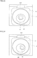
- FIG. 16 and FIG. 17 show a perspective view and a side sectional view, respectively, of the occupancy sensor 40.
- the occupancy sensor 40 is disposed inside an opening 40a of the housing 2. Over the opening 40a, there is disposed an accommodation chamber 40c which has an opening 40b in a front face thereof, and an operation lever 41 is disposed in the accommodation chamber 40c.
- the operation lever 41 is coupled to the occupancy sensor 40 via a rotation shaft 41a disposed at a rear end of the operation lever 41.
- the operation lever 41 and the occupancy sensor 40 are both rotatable about the rotation shaft 41a in the left-right direction.
- a recess 41a is formed, and in a front part of the operation lever 41, a convex part 41b is disposed behind the recess 41a to project upward in a hemispherical shape. As illustrated in FIG.
- a plurality (three, in the present embodiment) of concave parts 40d are aligned in the left-right direction, in each of which the convex part 41b is fittable.
- a lid 42 which is made of resin, openable and closable, and covers the operation lever 41.
- a lower end of the lid 42 is pivotally supported on the housing 2 via a horizontal shaft, and on a back of an upper end part of the lid 42, a projection 42a is disposed to project rearward to fit in the recess 41a of the operation lever 41.
- the lid 42 has an engagement claw 42b disposed at each side end part of the lid 42 to engage in one of engagement holes 42c of the housing 2, and, at an upper end of the lid 42, a handle 42d is disposed.
- a step part 40g is disposed, with a predetermined gap between the handle 42d and the step part 40g when the lid 42 is in a closed state. With this configuration, it is possible to easily hold the handle 42d of the lid 42 in the close state.
- the lid 42 has an opening 42f formed at a position opposing the occupancy sensor 40.
- a person who installs the air conditioner 1 holds the handle 42d and opens the lid 42. At this time, the engagement claw 42b is elastically deformed such that the engagement thereof with the engagement hole 42c is released.
- the operation lever 41 is rotated about the rotation shaft 41a in the left-right direction to fit the convex part 41b in a left one of the concave parts 40d. As a result, as illustrated in FIG. 19 , the operation lever 41 is inclined leftward such that a left side surface of the operation lever 41 contacts a left side surface of the accommodation chamber 40c. And, when the lid 42 is closed, a right side surface of the operation lever 41 is caught by the projection 42a, such that the occupancy sensor 40 is held pointing in a leftward direction as illustrated in FIG. 22 .
- the operation lever 41 is rotated to fit the convex part 41b in a middle one of the concave parts 40d. And, when the lid 42 is closed, as illustrated in FIG. 20 , the projection 42a of the lid 42 fits in the recess 41a of the operation lever 41, such that the occupancy sensor 40 is held pointing in a frontward direction as illustrated in FIG. 23 .
- the operation lever 41 is rotated to fit the convex part 41b in a right one of the concave parts 40d.
- the operation lever 41 is inclined rightward such that the right side surface of the operation lever 41 contacts a right side surface of the accommodation chamber 40c.
- the lid 42 is closed, the left side surface of the operation lever 41 is caught by the projection 42a, such that the occupancy sensor 40 is held pointing in a rightward direction as illustrated in FIG. 24 .
- the pointing operation of the occupancy sensor 40 is changeable in the left-right direction by operating the operation lever 41. This makes it possible to optimize the detection range of the occupancy sensor 40 in accordance with the installation position of the air conditioner 1 to allow secure detection of a human body existing in the room.
- the person who installs the air conditioner 1 does not need to touch the occupancy sensor 40 to change its direction. This helps protect the occupancy sensor 40 from being touched with a finger to be soiled.
- the wind direction plates 12 of the wind direction plate unit 10 rotates in the left-right direction such that air is discharged through the outlet 5 avoiding the detected human body. Thereby, it is possible to prevent the user from continuously receiving wind directly from the air conditioner 1, and this helps reduce damage to the user's health.
- the air conditioner 1 further includes the occupancy sensor 40 which detects a human body existing in the room, and discharges air through the outlet 5, avoiding the human body by means of the wind direction plates 12 of the wind direction plate unit 10. Thereby, it is possible to prevent wind from continuously blowing directly to the user, and thus to reduce damage to his or her health.
- the air conditioner 1 further includes the operation lever 41, which is coupled to the occupancy sensor 40, and makes it possible to change the direction of the occupancy sensor 40 in the left-right direction. This allows a person who installs the air conditioner 1 to change the direction of the occupancy sensor 40 without touching the occupancy sensor 40. Thus, it is possible to reduce soiling of the occupancy sensor 40 caused by being touched with a finger. Further, since the operation lever 41 is covered by the lid 42, the direction of the occupancy sensor 40 is prevented from being unintendedly changed by, for example, the person who installs the air conditioner 1, the user, or the like.
- the direction of the occupancy sensor 40 is variable between three directions by selectively holding one of the following three states: a state where the operation lever 41 is inclined leftward, with the right side surface thereof caught by the projection 42a (first state); a state where the projection 42a fits in the recess 41a of the operation lever 41 (second state); and a state where the operation lever 41 is inclined rightward, with the left side surface thereof caught by the projection 42a (third state).
- FIG. 25 shows a top view of a wind direction plate unit 10 of an air conditioner 1 of the third embodiment.
- a base part 11 of the wind direction plate unit 10 has a configuration different from its counterpart in the first embodiment.
- the third embodiment is similar to the first embodiment.
- a plurality of projections 11b are arranged parallel to each other at predetermined intervals in a front-rear direction.
- the position of the press member 19 coincides with the position of the projections 11b in the left-right direction.
- the projections 11b project upward from a flat surface 11c of the base part 11 such that a height (an amount of projection from the flat surface 11c) of each projection 11b is approximately 0.5 mm.
- the projections 11b and the flat surface 11c between adjacent ones of the projections 11b together form an uneven 11d.
- the uneven part 11d functions as an anti-slip surface when the user holds the wind direction plate unit 10 with his or her fingers at the position of the press member 19 in the up-down direction, and allows the user to securely hold the wind direction plate unit 10 while pressing the press member 19 upward. This further improves the user-friendliness of the air conditioner 1.
- the projections 11b do not become a large resistance to air flowing in the air passage 6, and thus does not very much hinder the blowing performance of the air conditioner 1.
- the uneven part 11d is disposed on the outer surface of the base part 11 such that the position of the press member 19 and that of the uneven part 11d coincide with each other in the left-right direction. Thereby, it is possible for the user to securely hold the wind direction plate unit 10 in detaching the wind direction plate unit 10.
- an uneven part may be formed by arranging dotted projections, instead of the linear projections 11b, in a matrix pattern on the outer surface of the base part 11.
- an uneven part similar to the uneven part 11d of the present embodiment may be disposed in the air conditioner 1 of the second embodiment.
- the present invention is applicable to air conditioners having a wind direction plate which changes the direction of air discharged through an outlet in the left-right direction.
Landscapes
- Engineering & Computer Science (AREA)
- Chemical & Material Sciences (AREA)
- Combustion & Propulsion (AREA)
- Mechanical Engineering (AREA)
- General Engineering & Computer Science (AREA)
- Air-Flow Control Members (AREA)
- Air Filters, Heat-Exchange Apparatuses, And Housings Of Air-Conditioning Units (AREA)
- Air Conditioning Control Device (AREA)
Applications Claiming Priority (2)
| Application Number | Priority Date | Filing Date | Title |
|---|---|---|---|
| JP2015209257A JP6633345B2 (ja) | 2015-10-23 | 2015-10-23 | 空気調和機 |
| PCT/JP2016/075200 WO2017068862A1 (fr) | 2015-10-23 | 2016-08-29 | Climatiseur |
Publications (2)
| Publication Number | Publication Date |
|---|---|
| EP3367015A1 true EP3367015A1 (fr) | 2018-08-29 |
| EP3367015A4 EP3367015A4 (fr) | 2019-09-11 |
Family
ID=58557233
Family Applications (1)
| Application Number | Title | Priority Date | Filing Date |
|---|---|---|---|
| EP16857180.0A Withdrawn EP3367015A4 (fr) | 2015-10-23 | 2016-08-29 | Climatiseur |
Country Status (4)
| Country | Link |
|---|---|
| EP (1) | EP3367015A4 (fr) |
| JP (1) | JP6633345B2 (fr) |
| CN (1) | CN108139111B (fr) |
| WO (1) | WO2017068862A1 (fr) |
Families Citing this family (8)
| Publication number | Priority date | Publication date | Assignee | Title |
|---|---|---|---|---|
| CN107702307B (zh) * | 2017-09-12 | 2023-07-14 | 珠海格力电器股份有限公司 | 导风板机构及具有其的空调器 |
| JP7037575B2 (ja) * | 2017-10-18 | 2022-03-16 | シャープ株式会社 | 空調機 |
| JP7033934B2 (ja) * | 2018-01-22 | 2022-03-11 | 三菱電機株式会社 | コントローラ、冷却システム、冷却装置の制御方法、及び、プログラム |
| EP3786542B1 (fr) * | 2018-04-24 | 2023-10-25 | Mitsubishi Electric Corporation | Mécanisme de réglage de direction du vent, unité intérieure de climatiseur et climatiseur |
| CN109654599B (zh) * | 2018-10-26 | 2021-03-16 | 青岛海尔空调器有限总公司 | 一种壁挂式空调室内机及控制方法 |
| JP7246911B2 (ja) * | 2018-12-17 | 2023-03-28 | シャープ株式会社 | 空気調和機 |
| CN111336676A (zh) * | 2018-12-18 | 2020-06-26 | 奥克斯空调股份有限公司 | 一种扫风叶片装配机构及相应扫风叶片与空调器 |
| JP7579165B2 (ja) * | 2021-02-04 | 2024-11-07 | シャープ株式会社 | 空気調和機 |
Family Cites Families (11)
| Publication number | Priority date | Publication date | Assignee | Title |
|---|---|---|---|---|
| JPH10253146A (ja) * | 1997-03-14 | 1998-09-25 | Hitachi Ltd | 風向調節装置及びそれを用いた空気調和機 |
| JP2001227812A (ja) * | 2000-02-17 | 2001-08-24 | Sharp Corp | 空気調和機 |
| JP2004219049A (ja) * | 2002-12-25 | 2004-08-05 | Sanyo Electric Co Ltd | 空気調和機 |
| JP2005127671A (ja) * | 2003-10-27 | 2005-05-19 | Sharp Corp | 空気調和機 |
| JP3952035B2 (ja) * | 2004-04-22 | 2007-08-01 | 三菱電機株式会社 | 空気調和機、空気調和機の清掃方法 |
| JP5009049B2 (ja) * | 2007-05-23 | 2012-08-22 | パナソニック株式会社 | 空気調和機 |
| CN103017300B (zh) * | 2008-02-08 | 2015-04-15 | 松下电器产业株式会社 | 空气调节机 |
| KR101356650B1 (ko) * | 2008-02-12 | 2014-02-05 | 삼성전자주식회사 | 공기조화기의 실내기 |
| JP4698747B2 (ja) * | 2009-08-19 | 2011-06-08 | シャープ株式会社 | 壁掛け形空気調和機 |
| JP4965618B2 (ja) * | 2009-09-15 | 2012-07-04 | シャープ株式会社 | 空気調節装置の風向変更装置 |
| CN103528175B (zh) * | 2013-10-09 | 2017-09-15 | Tcl空调器(中山)有限公司 | 空调器及其导风装置 |
-
2015
- 2015-10-23 JP JP2015209257A patent/JP6633345B2/ja active Active
-
2016
- 2016-08-29 WO PCT/JP2016/075200 patent/WO2017068862A1/fr not_active Ceased
- 2016-08-29 CN CN201680051080.0A patent/CN108139111B/zh active Active
- 2016-08-29 EP EP16857180.0A patent/EP3367015A4/fr not_active Withdrawn
Also Published As
| Publication number | Publication date |
|---|---|
| EP3367015A4 (fr) | 2019-09-11 |
| WO2017068862A1 (fr) | 2017-04-27 |
| JP6633345B2 (ja) | 2020-01-22 |
| JP2017083040A (ja) | 2017-05-18 |
| CN108139111A (zh) | 2018-06-08 |
| CN108139111B (zh) | 2021-06-29 |
Similar Documents
| Publication | Publication Date | Title |
|---|---|---|
| EP3367015A1 (fr) | Climatiseur | |
| JP5108119B2 (ja) | ダストボックス、フィルタ清掃装置および空気調和機 | |
| JP5108121B2 (ja) | フィルタ保持装置、フィルタ清掃装置および空気調和機 | |
| JP2011064353A (ja) | 空気調和機 | |
| KR20150039399A (ko) | 카세트형 공기조화기의 실내기 | |
| JP5489956B2 (ja) | 空気調和機 | |
| WO2016199459A1 (fr) | Dispositif de nettoyage électrique | |
| CN102934536B (zh) | 通风设备 | |
| JP2003049812A (ja) | 脱着装置及び、それを用いた空気調和機 | |
| JP5108118B2 (ja) | フィルタ清掃装置、ダストボックスおよび空気調和機 | |
| JP5175943B2 (ja) | フィルタ清掃装置、ダストボックスおよび空気調和機 | |
| JP6726561B2 (ja) | 空気調和機 | |
| CN103250006A (zh) | 过滤器保持装置、过滤器清扫装置和空气调节机 | |
| JP2012145257A (ja) | フィルタ保持装置、フィルタ清掃装置および空気調和機 | |
| JP5777963B2 (ja) | レンジフード | |
| JP6469523B2 (ja) | 空気調和機 | |
| TWI609667B (zh) | 電動吸塵器 | |
| JP6124847B2 (ja) | 空気調和機用のフィルター清掃装置及び空気調和機 | |
| JP2020046091A (ja) | 風向き変更部材 | |
| KR20160015622A (ko) | 청소기 | |
| JP4969665B2 (ja) | 電気掃除機の吸込具及びその吸込具を備えた電気掃除機 | |
| JP2016038167A (ja) | 空気調和機用のフィルター清掃装置及び空気調和機 | |
| JP2007170789A (ja) | 空気調和機 | |
| CN212987436U (zh) | 吸顶式空调室内机 | |
| CN113940581B (zh) | 一种手持式吸尘装置及吸尘设备 |
Legal Events
| Date | Code | Title | Description |
|---|---|---|---|
| STAA | Information on the status of an ep patent application or granted ep patent |
Free format text: STATUS: THE INTERNATIONAL PUBLICATION HAS BEEN MADE |
|
| PUAI | Public reference made under article 153(3) epc to a published international application that has entered the european phase |
Free format text: ORIGINAL CODE: 0009012 |
|
| STAA | Information on the status of an ep patent application or granted ep patent |
Free format text: STATUS: REQUEST FOR EXAMINATION WAS MADE |
|
| 17P | Request for examination filed |
Effective date: 20180228 |
|
| AK | Designated contracting states |
Kind code of ref document: A1 Designated state(s): AL AT BE BG CH CY CZ DE DK EE ES FI FR GB GR HR HU IE IS IT LI LT LU LV MC MK MT NL NO PL PT RO RS SE SI SK SM TR |
|
| AX | Request for extension of the european patent |
Extension state: BA ME |
|
| DAV | Request for validation of the european patent (deleted) | ||
| DAX | Request for extension of the european patent (deleted) | ||
| RIC1 | Information provided on ipc code assigned before grant |
Ipc: F24F 13/20 20060101AFI20170508BHEP Ipc: F24F 11/02 20060101ALI20170508BHEP Ipc: F24F 13/15 20060101ALI20170508BHEP |
|
| RIC1 | Information provided on ipc code assigned before grant |
Ipc: F24F 11/49 20180101ALI20190416BHEP Ipc: F24F 13/20 20060101AFI20190416BHEP Ipc: F24F 13/15 20060101ALI20190416BHEP Ipc: F24F 120/12 20180101ALI20190416BHEP |
|
| A4 | Supplementary search report drawn up and despatched |
Effective date: 20190812 |
|
| RIC1 | Information provided on ipc code assigned before grant |
Ipc: F24F 13/20 20060101AFI20190806BHEP Ipc: F24F 120/12 20180101ALI20190806BHEP Ipc: F24F 11/49 20180101ALI20190806BHEP Ipc: F24F 13/15 20060101ALI20190806BHEP |
|
| STAA | Information on the status of an ep patent application or granted ep patent |
Free format text: STATUS: THE APPLICATION IS DEEMED TO BE WITHDRAWN |
|
| 18D | Application deemed to be withdrawn |
Effective date: 20210302 |