EP3367128B1 - Dispositif de surveillance - Google Patents
Dispositif de surveillance Download PDFInfo
- Publication number
- EP3367128B1 EP3367128B1 EP17157309.0A EP17157309A EP3367128B1 EP 3367128 B1 EP3367128 B1 EP 3367128B1 EP 17157309 A EP17157309 A EP 17157309A EP 3367128 B1 EP3367128 B1 EP 3367128B1
- Authority
- EP
- European Patent Office
- Prior art keywords
- sensor
- arrangement according
- surveillance
- data
- control data
- Prior art date
- Legal status (The legal status is an assumption and is not a legal conclusion. Google has not performed a legal analysis and makes no representation as to the accuracy of the status listed.)
- Active
Links
Images
Classifications
-
- G—PHYSICS
- G01—MEASURING; TESTING
- G01S—RADIO DIRECTION-FINDING; RADIO NAVIGATION; DETERMINING DISTANCE OR VELOCITY BY USE OF RADIO WAVES; LOCATING OR PRESENCE-DETECTING BY USE OF THE REFLECTION OR RERADIATION OF RADIO WAVES; ANALOGOUS ARRANGEMENTS USING OTHER WAVES
- G01S17/00—Systems using the reflection or reradiation of electromagnetic waves other than radio waves, e.g. lidar systems
- G01S17/02—Systems using the reflection of electromagnetic waves other than radio waves
- G01S17/06—Systems determining position data of a target
-
- G—PHYSICS
- G01—MEASURING; TESTING
- G01D—MEASURING NOT SPECIALLY ADAPTED FOR A SPECIFIC VARIABLE; ARRANGEMENTS FOR MEASURING TWO OR MORE VARIABLES NOT COVERED IN A SINGLE OTHER SUBCLASS; TARIFF METERING APPARATUS; MEASURING OR TESTING NOT OTHERWISE PROVIDED FOR
- G01D5/00—Mechanical means for transferring the output of a sensing member; Means for converting the output of a sensing member to another variable where the form or nature of the sensing member does not constrain the means for converting; Transducers not specially adapted for a specific variable
- G01D5/26—Mechanical means for transferring the output of a sensing member; Means for converting the output of a sensing member to another variable where the form or nature of the sensing member does not constrain the means for converting; Transducers not specially adapted for a specific variable characterised by optical transfer means, i.e. using infrared, visible, or ultraviolet light
- G01D5/32—Mechanical means for transferring the output of a sensing member; Means for converting the output of a sensing member to another variable where the form or nature of the sensing member does not constrain the means for converting; Transducers not specially adapted for a specific variable characterised by optical transfer means, i.e. using infrared, visible, or ultraviolet light with attenuation or whole or partial obturation of beams of light
- G01D5/34—Mechanical means for transferring the output of a sensing member; Means for converting the output of a sensing member to another variable where the form or nature of the sensing member does not constrain the means for converting; Transducers not specially adapted for a specific variable characterised by optical transfer means, i.e. using infrared, visible, or ultraviolet light with attenuation or whole or partial obturation of beams of light the beams of light being detected by photocells
- G01D5/347—Mechanical means for transferring the output of a sensing member; Means for converting the output of a sensing member to another variable where the form or nature of the sensing member does not constrain the means for converting; Transducers not specially adapted for a specific variable characterised by optical transfer means, i.e. using infrared, visible, or ultraviolet light with attenuation or whole or partial obturation of beams of light the beams of light being detected by photocells using displacement encoding scales
- G01D5/34746—Linear encoders
-
- G—PHYSICS
- G01—MEASURING; TESTING
- G01D—MEASURING NOT SPECIALLY ADAPTED FOR A SPECIFIC VARIABLE; ARRANGEMENTS FOR MEASURING TWO OR MORE VARIABLES NOT COVERED IN A SINGLE OTHER SUBCLASS; TARIFF METERING APPARATUS; MEASURING OR TESTING NOT OTHERWISE PROVIDED FOR
- G01D5/00—Mechanical means for transferring the output of a sensing member; Means for converting the output of a sensing member to another variable where the form or nature of the sensing member does not constrain the means for converting; Transducers not specially adapted for a specific variable
- G01D5/26—Mechanical means for transferring the output of a sensing member; Means for converting the output of a sensing member to another variable where the form or nature of the sensing member does not constrain the means for converting; Transducers not specially adapted for a specific variable characterised by optical transfer means, i.e. using infrared, visible, or ultraviolet light
- G01D5/32—Mechanical means for transferring the output of a sensing member; Means for converting the output of a sensing member to another variable where the form or nature of the sensing member does not constrain the means for converting; Transducers not specially adapted for a specific variable characterised by optical transfer means, i.e. using infrared, visible, or ultraviolet light with attenuation or whole or partial obturation of beams of light
- G01D5/34—Mechanical means for transferring the output of a sensing member; Means for converting the output of a sensing member to another variable where the form or nature of the sensing member does not constrain the means for converting; Transducers not specially adapted for a specific variable characterised by optical transfer means, i.e. using infrared, visible, or ultraviolet light with attenuation or whole or partial obturation of beams of light the beams of light being detected by photocells
- G01D5/347—Mechanical means for transferring the output of a sensing member; Means for converting the output of a sensing member to another variable where the form or nature of the sensing member does not constrain the means for converting; Transducers not specially adapted for a specific variable characterised by optical transfer means, i.e. using infrared, visible, or ultraviolet light with attenuation or whole or partial obturation of beams of light the beams of light being detected by photocells using displacement encoding scales
- G01D5/34776—Absolute encoders with analogue or digital scales
- G01D5/34792—Absolute encoders with analogue or digital scales with only digital scales or both digital and incremental scales
-
- G—PHYSICS
- G01—MEASURING; TESTING
- G01S—RADIO DIRECTION-FINDING; RADIO NAVIGATION; DETERMINING DISTANCE OR VELOCITY BY USE OF RADIO WAVES; LOCATING OR PRESENCE-DETECTING BY USE OF THE REFLECTION OR RERADIATION OF RADIO WAVES; ANALOGOUS ARRANGEMENTS USING OTHER WAVES
- G01S17/00—Systems using the reflection or reradiation of electromagnetic waves other than radio waves, e.g. lidar systems
- G01S17/02—Systems using the reflection of electromagnetic waves other than radio waves
- G01S17/06—Systems determining position data of a target
- G01S17/42—Simultaneous measurement of distance and other co-ordinates
-
- G—PHYSICS
- G01—MEASURING; TESTING
- G01S—RADIO DIRECTION-FINDING; RADIO NAVIGATION; DETERMINING DISTANCE OR VELOCITY BY USE OF RADIO WAVES; LOCATING OR PRESENCE-DETECTING BY USE OF THE REFLECTION OR RERADIATION OF RADIO WAVES; ANALOGOUS ARRANGEMENTS USING OTHER WAVES
- G01S17/00—Systems using the reflection or reradiation of electromagnetic waves other than radio waves, e.g. lidar systems
- G01S17/88—Lidar systems specially adapted for specific applications
- G01S17/89—Lidar systems specially adapted for specific applications for mapping or imaging
-
- G—PHYSICS
- G01—MEASURING; TESTING
- G01S—RADIO DIRECTION-FINDING; RADIO NAVIGATION; DETERMINING DISTANCE OR VELOCITY BY USE OF RADIO WAVES; LOCATING OR PRESENCE-DETECTING BY USE OF THE REFLECTION OR RERADIATION OF RADIO WAVES; ANALOGOUS ARRANGEMENTS USING OTHER WAVES
- G01S7/00—Details of systems according to groups G01S13/00, G01S15/00, G01S17/00
- G01S7/48—Details of systems according to groups G01S13/00, G01S15/00, G01S17/00 of systems according to group G01S17/00
- G01S7/497—Means for monitoring or calibrating
Definitions
- the invention relates to a monitoring arrangement according to the preamble of claim 1.
- the monitoring arrangement generally comprises a sensor that is assigned to a system.
- the sensor is used to detect an object that can be used in particular to control the system.
- Such a monitoring arrangement is from DE 102 11 779 B1 known.
- the monitoring arrangement described there has an optical sensor with a transmitter emitting transmitted light rays, a receiver receiving received light rays, means for guiding the transmitted light rays within a scanning area and an evaluation unit for evaluating the received signals at the output of the receiver.
- the optical sensor is used to detect marks, which form a position measurement system. By detecting marks of the position measuring system at two different points in time, the speed of the optical sensor is also determined relative to the position measuring system.
- the optical sensor is particularly advantageously attached to a vehicle, the position measurement system being arranged in a stationary manner on the roadway along which the vehicle is moved.
- a position measurement system can also be moved with respect to a stationary optoelectronic device. Due to the continuous detection of the marks of the position measuring system, the current speed and position measurement values are continuously determined in the optical sensor and transmitted to the control of the vehicle. These measured values can be used in the control without further evaluation and in particular, can be used directly to control the vehicle without any synchronization effort.
- compliance with predetermined speed profiles for the vehicle can be continuously monitored in the controller. Together with the current information about the position of the vehicle, it can be retracted reproducibly and precisely to specified target positions.
- the EP 1 345 031 A2 relates to an optoelectronic device for detecting marks and has a transmitter emitting transmitted light rays, a receiver receiving received light rays, means for guiding the transmitted light rays within a scanning area and an evaluation unit for evaluating the received signals at the output of the receiver.
- the marks to be recorded form a position measurement system.
- the U.S. 4,901,073 A relates to an optical sensor system for determining the absolute position of a moving object relative to a stationary object.
- the sensor system comprises a barcode scanner by means of which barcodes arranged on a belt are recorded. Their absolute position in the tape is coded in the barcodes.
- the barcodes can also contain control characters such as start or stop characters. This allows the scanning direction in which the barcode scanner scans the barcodes to be detected.
- the DE 10 2006 025 045 A1 relates to an optoelectronic device comprising a sensor with a transmitter emitting a transmission light beam, a receiving light beam receiving receiver, means for guiding the transmission light beams within a scanning area and an evaluation unit for evaluating the received signals at the output of the receiver and a position measurement system formed from an arrangement of marks.
- the sensor's position relative to the position measurement system can be determined.
- the transmitter of the sensor is switched off during predetermined time intervals.
- the US 2017/0018188 A1 relates to a detection system on a vehicle that is designed to determine the orientation to a lane boundary.
- the invention is based on the object of providing a monitoring arrangement with increased functionality.
- the invention relates to a monitoring arrangement with a sensor assigned to a system.
- the sensor has at least one sensor element and an evaluation unit, the sensor element being designed to detect objects within a monitoring area assigned to the system and the evaluation unit being designed to generate object detection data as a function of sensor signals from the sensor element.
- a memory unit is provided in which control data generated as a function of the object detection data are stored in a tamper-proof manner by means of a checksum. The function of the system and the sensor can be controlled using the control data.
- the basic idea of the invention is therefore to use the sensor of the monitoring arrangement not only for object detection.
- the functionality of the sensor and thus of the monitoring arrangement is increased by the fact that control data are generated by means of the sensor or a further unit as a function of the object detection data of the sensor and are stored in a tamper-proof manner, i.e. falsification of the control data can be safely recognized.
- the control data thus form fail-safe data that in particular, form a time-resolved sequence of control data, on the basis of which the function of the system and also the function of the sensor can be checked.
- control function which runs automatically as a result, makes manual interventions to control the system and the sensor largely superfluous, which considerably increases the functionality of the monitoring arrangement.
- the senor can advantageously be designed as a safety sensor.
- the safety sensor has an evaluation unit with a redundant structure, in particular in the form of two computer units that monitor each other cyclically.
- the sensor is used in particular for positioning tasks. This is particularly useful when the system is a vehicle, such as a driverless transport system.
- the sensor is arranged on the vehicle and detects defined, stationary cooperative targets arranged in the monitoring area. Based on the detection of the cooperative targets, the sensor generates object detection data that can be used to position the vehicle.
- the senor is an optical sensor.
- the senor is designed as a distance sensor, by means of which the distances to cooperative targets are determined, which can be designed, for example, in the form of reflectors.
- the position of the vehicle and also its speed can be determined on the basis of the distance values.
- the distance sensor can have a transmitter and a receiver, the transmitter having light beams in a fixed, predetermined direction emitted, which are reflected back to the receiver by a cooperative target, which can be formed by a photodiode.
- the distance measurement can take place, for example, according to a pulse transit time method.
- the distance sensor can be expanded in such a way that it not only has a single receiver such as a photodiode, but can also have a line-shaped or matrix-shaped arrangement of receiving elements, that is, the receiver is formed by a camera. In this case, a distance measurement is carried out with each receiving element so that a 3D measurement of objects is possible.
- the distance sensor can be developed as an alternative to a scanning distance sensor, that is, the light beams emitted by the transmitter are periodically guided in a detection area.
- this can be realized in that the transmitter and the receiver are integrated in a rotating measuring head, so that the light beams are periodically guided in the detection area by the rotary movement of the measuring head.
- the transmitter and receiver can be housed stationary in a housing of the sensor, with a deflection unit, for example in the form of a motor-driven rotating mirror, assigned to them, so that the light beams are periodically guided in the detection area by means of the deflection unit.
- the cooperative goals are formed by marks of a position measurement system. Their position in the monitoring area is then coded in the individual marks, so that the totality of the marks forms a measuring tape.
- the sensor is designed as a code reader. By detecting the marks by means of the code reader, the position of the code reader and thus of the vehicle on which the code reader is arranged is determined.
- the correct arrangement of the cooperative targets in particular the position measurement system, can be checked, so that a complex manual check of the cooperative targets is not necessary.
- control data are stored in a manipulation-proof manner by means of a checksum.
- control data stored as a time-resolved sequence of data can advantageously be identified and individualized in that they are stored with at least one assignment feature.
- allocation features allow the stored control data to be clearly allocated to individual data records.
- These allocation features can for example be entered by a user via an input unit.
- the allocation features can also be generated automatically in the system.
- the assignment features can be formed by trigger signals that a control unit of the system generates.
- the allocation features are formed by time stamps.
- time stamps clearly identify the control data in that the times at which these control data were generated are documented. This allows the function of the sensor and the entire monitoring arrangement to be checked in a time-resolved manner.
- the storage unit is particularly advantageously integrated in a control unit of the system.
- control data can be obtained from the object detection data of the sensor and stored in the memory unit.
- control and monitoring functions can still be carried out on the basis of the control data.
- control data can then in particular be used directly as maintenance data.
- maintenance data are generated in the control unit as a function of the control data. It is advantageous here that such maintenance data, which can be used for maintenance of the system, can be generated while the system is in operation, that is, the system no longer has to be switched to maintenance mode for this purpose, which can significantly reduce system downtimes.
- control data or maintenance data can be transmitted from the control unit of the system to external units via suitable interfaces, such as bus systems, for example.
- suitable interfaces such as bus systems, for example.
- Such an external unit can be formed by a recording device in which the control data or maintenance data are recorded. Furthermore, a further evaluation of the control data or maintenance data can also take place in an external unit.
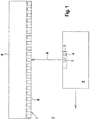
- FIG 1 shows schematically an embodiment of the monitoring arrangement 1 according to the invention.
- the monitoring arrangement 1 has a sensor in the form of an optical sensor 2 with a sensor element 3 and an evaluation unit 4.
- the optical sensor 2 is designed as a safety sensor.
- the evaluation unit 4 has a redundant structure, for example in the form of two computer units that monitor each other cyclically.
- the optical sensor 2 is mounted on a vehicle 5 forming a system, which in the present exemplary embodiment is formed by a track-guided sliding carriage.
- vehicle 5 can be formed by an overhead conveyor, a storage and retrieval unit, a crane or the like.
- the roadway is laterally delimited by a roadway delimitation 6, such as a guardrail, for example.
- a position measurement system 7 is applied, which forms an arrangement with cooperative goals.
- the position measuring system 7 is designed as a measuring tape which can be glued to a base.
- the measuring tape consists of a sequence of marks in the form of barcodes 8 arranged one behind the other in the longitudinal direction of the position scale 7.
- Each barcode 8 is applied to a separate segment of the measuring tape, with adjacent segments being separated by a cutting gap.
- the segments each have an identical width. The widths of the cutting gaps between the individual segments are also constant.
- the individual segments thus form identical scale modules, so that a given length of the tape measure is given by the number of segments multiplied by the width of the segments and the width of the respective subsequent cutting gap.
- the segments within the measuring tape are numbered consecutively so that each number of a segment encodes the position within the measuring tape.
- the number of a segment is coded in the respective barcode 8.
- the barcodes 8 of the position measurement system 7 are scanned and recorded one after the other as the vehicle 5 drives past.
- the barcodes 8 are decoded in the evaluation unit 4.
- the position of the vehicle 5 relative to the position measurement system 7 is continuously determined with the optical sensor 2.
- the speed of the vehicle 5 can also be determined from the time sequence of the signals detected by the optical sensor 2.
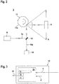
- FIG. 2 shows an embodiment of the sensor elements 3 of the optical sensor 2.
- the optical sensor 2 is designed in this case as a scanning code reader and comprises a transmitter 9 emitting transmitted light beams 9a and a receiver 10 which receives received light beams 10a.
- the transmitted light beams 9a emitted by the transmitter 9 and those from a Received light beams 10a reflected back from the barcode 8 are guided via a deflection unit in the form of a polygonal mirror wheel 11 which has a plurality of reflective facets 11a and can be rotated about an axis of rotation.
- a deflecting mirror 12 By means of a deflecting mirror 12, a coaxial beam guidance of transmitted light rays 9a and received light rays 10a is achieved.
- the transmitted light beams 9a are periodically guided within a scanning area A.
- Figure 3 shows a control unit 13 of the vehicle 5 or generally of the system.
- the vehicle 5 is controlled as a function of the position values detected with the optical sensor 2; in particular, the vehicle 5 is positioned at specific positions along the roadway.
- the control unit 13 has a memory unit 14 in which control data a are stored in a tamper-proof manner. Tamper-proof storage takes place with a checksum b.
- the control data a are assigned assignment features c, which are also secured with the checksum b.
- control data a are derived directly from the object detection data of the optical sensor 2.
- a time sequence of determined position and / or speed values of the vehicle 5, which were determined with the optical sensor 2 can be stored as control data a in the memory unit 14.
- These measured values are advantageously stored with assignment features c in the form of time stamps, so that the times of the measured value generation are stored with the control data a.
- other association features c characterizing the control data a can also be specified, for example by user inputs or by the control unit 13 itself.
- control and monitoring functions can be carried out in the control unit 13. For example, the position and / or speed values forming the control data a can be compared with predefined setpoint values. If the control data a deviate from the setpoint values by a predetermined amount, an emergency stop of the vehicle 5 can be triggered in the control unit 13, for example.
- maintenance data for the vehicle 5 can be derived from the control data a in the control unit 13.
- the object detection data of the optical sensor 2 and, if necessary, external data of the vehicle 5 (indicated by the arrow c) and internal data of the control unit 13 (indicated by the arrow d) are evaluated in the control unit 13, in particular in order to describe or analyze specific system situations.
- the control data a can be used to record an emergency braking of the vehicle 5 as a specific system situation, whereby, in addition to the position and speed values of the optical sensor 2, vehicle parameters or internal control parameters are also used to generate the maintenance data.
- Such maintenance data can, for example, document the braking distance of the vehicle 5 during a braking process.
- the maintenance data can document whether the position measuring system 7 is correctly arranged or whether it is damaged.
- the control data a which are stored in the memory unit 14, can be read out to an external unit via an interface 15 such as a bus system.
- the external unit can be, for example, a recording device, where the control data a is permanently stored for documentation purposes. Alternatively, further evaluations of the control data a can take place in the external unit.
Landscapes
- Physics & Mathematics (AREA)
- Engineering & Computer Science (AREA)
- General Physics & Mathematics (AREA)
- Electromagnetism (AREA)
- Computer Networks & Wireless Communication (AREA)
- Radar, Positioning & Navigation (AREA)
- Remote Sensing (AREA)
- Length Measuring Devices By Optical Means (AREA)
- Traffic Control Systems (AREA)
Claims (16)
- Dispositif de surveillance (1) avec un capteur associé à une installation, le capteur présentant au moins un élément capteur (3) et une unité d'évaluation (4), l'élément capteur (3) étant conçu pour détecter des objets dans une zone desurveillance associée à l'installation et l'unité d'évaluation (4) étant conçue pourdétecter des objets dans une zone desurveillance associée à l'installation,pour générer des données dedétection d'objet en fonction des signaux de capteur de l'élément capteur (3), caractérisé en ce qu'il est prévu une unité de mémoire (14) dans laquelle des données de commande (a) générées en fonction des données de détection d'objet sont restituées de manière inviolable au moyen d'une somme de contrôle (b), le fonctionnement du système et du capteur pouvant être vérifié au moyen des données de commande (a).
- Dispositif de surveillance selon la revendication 1, caractérisé par le fait que les cibles coopératives peuvent être détectées au moyen du capteur.
- Dispositif de surveillance selon l'une des revendications 1 ou 2, caractérisé en ce que le capteur est un capteur de distance.
- Dispositif de surveillance selon la revendication 2, caractérisé en ce que les objectifs de coopération des marques sont d'un système de mesure de position (7).
- Dispositif de surveillance selon la revendication 4,caractérisé en ce que le capteur est un lecteur de code.
- Dispositif de surveillance selon l'une des revendications 1 à 5, caractérisé en ce que le dispositif est un véhicule (5), en particulier un système de transport sans conducteur .
- Dispositif de surveillance selon l'une des revendications 1 à 6, caractérisé en ce que le capteur est relié à l'installation.
- Dispositif de surveillance selon l'une des revendications 2 à 7, caractérisé en ce que les cibles coopératives sont disposéesde manière stationnaire dans la zone de surveillance.
- Dispositif de surveillance selon l'une des revendications 1 à 8, caractérisé en ce que les données de surveillance (a) sont stockées avec au moins une caractéristique d'attribution (c).
- Dispositif de surveillance selon la revendication 9, caractérisé en ce que les caractéristiques d'attribution (c) sont générées par les entrées de l'opérateur ou automatiquement par l'installation.
- Dispositif de surveillance selon la revendication 9, caractérisé en ce que les caractéristiques d'attribution (c) sont formées par des estampilles temporelles.
- Dispositif de surveillance selon l'une des revendications 9 à 11, indique ainsi que les données de contrôle (a) avec les caractéristiques d'affectation (c) sont stockées de manière inviolable au moyen d'une somme de contrôle.
- Dispositif de surveillance selon l'une des revendications 1 à 12, caractérisé en ce que l'unité de mémoire (14) est intégrée dans une unité de commande (13) de l'installation.
- Dispositif de surveillance selon l'une des revendications 1 à 13, caractérisé en ce que les données de contrôle (a) sont des données de maintenance ou que les données de maintenance sont obtenues par l'évaluation des données de contrôle (a).
- Dispositif de surveillance selon la revendication 14, caractérisé en ce qu'une distance de freinage d'un véhicule (5) ou l'état d'un système de mesure de position (7) est documenté avec les données de maintenance.
- Dispositif de surveillance selon la revendication 14, caractérisé en ce que les données de contrôle (a) ou les données de maintenance sont évaluées et/ou enregistrées dans une unité externe .
Priority Applications (1)
| Application Number | Priority Date | Filing Date | Title |
|---|---|---|---|
| EP17157309.0A EP3367128B1 (fr) | 2017-02-22 | 2017-02-22 | Dispositif de surveillance |
Applications Claiming Priority (1)
| Application Number | Priority Date | Filing Date | Title |
|---|---|---|---|
| EP17157309.0A EP3367128B1 (fr) | 2017-02-22 | 2017-02-22 | Dispositif de surveillance |
Publications (2)
| Publication Number | Publication Date |
|---|---|
| EP3367128A1 EP3367128A1 (fr) | 2018-08-29 |
| EP3367128B1 true EP3367128B1 (fr) | 2020-10-28 |
Family
ID=58192103
Family Applications (1)
| Application Number | Title | Priority Date | Filing Date |
|---|---|---|---|
| EP17157309.0A Active EP3367128B1 (fr) | 2017-02-22 | 2017-02-22 | Dispositif de surveillance |
Country Status (1)
| Country | Link |
|---|---|
| EP (1) | EP3367128B1 (fr) |
Families Citing this family (3)
| Publication number | Priority date | Publication date | Assignee | Title |
|---|---|---|---|---|
| DE102021103952A1 (de) * | 2021-02-19 | 2022-08-25 | Sick Ag | Optoelektronische Sicherheitsvorrichtung |
| EP4403881A1 (fr) * | 2023-01-19 | 2024-07-24 | Leuze electronic GmbH + Co. KG | Agencement de capteur et procédé de fonctionnement d'un agencement de capteur |
| DE202024104318U1 (de) * | 2024-08-01 | 2025-11-20 | Leuze Electronic Gmbh + Co. Kg | Sensoranordnung |
Family Cites Families (4)
| Publication number | Priority date | Publication date | Assignee | Title |
|---|---|---|---|---|
| US4901073A (en) * | 1986-12-04 | 1990-02-13 | Regent Of The University Of California | Encoder for measuring the absolute position of moving elements |
| DE10211779B4 (de) * | 2002-03-16 | 2005-03-31 | Leuze Electronic Gmbh & Co Kg | Optoelektronische Vorrichtung |
| DE102006025045B4 (de) * | 2006-05-30 | 2008-08-07 | Leuze Electronic Gmbh + Co. Kg | Verfahren zum Betrieb einer optoelektronischen Vorrichtung |
| JP6374695B2 (ja) * | 2014-04-28 | 2018-08-15 | 日立建機株式会社 | 路肩検出システムおよび鉱山用運搬車両 |
-
2017
- 2017-02-22 EP EP17157309.0A patent/EP3367128B1/fr active Active
Non-Patent Citations (1)
| Title |
|---|
| None * |
Also Published As
| Publication number | Publication date |
|---|---|
| EP3367128A1 (fr) | 2018-08-29 |
Similar Documents
| Publication | Publication Date | Title |
|---|---|---|
| EP2728305B1 (fr) | Procédé et motif lumineux pour mesurer la hauteur ou le trajet en hauteur d'un objet | |
| EP1494048B1 (fr) | Rideau de lumière | |
| EP1788467B1 (fr) | Dispositif de protection | |
| EP1548351A2 (fr) | Dispositif de surveillance d'une zone de couverture près d'une machine | |
| DE10312972B3 (de) | Optischer Sensor | |
| EP2083209A1 (fr) | Système de sécurité destiné à la mesure sans contact de voies et/ou de vitesses | |
| EP3401702B1 (fr) | Système de capteur | |
| EP3587894B1 (fr) | Agencement de capteurs et procédé de fonctionnement d'un agencement de capteurs | |
| WO2009000727A1 (fr) | Capteur optique pour opérations de positionnement | |
| DE10211779B4 (de) | Optoelektronische Vorrichtung | |
| EP3270114B1 (fr) | Système de détection | |
| EP3367128A1 (fr) | Dispositif de surveillance | |
| EP3882505B1 (fr) | Dispositif de surveillance et procédé de fonctionnement d'un dispositif de surveillance | |
| EP3808687A1 (fr) | Système de surveillance de l'état d'un convoyeur et convoyeur avec système de surveillance | |
| EP3910547A1 (fr) | Détection des objets mobiles | |
| DE102005047658B4 (de) | Vorrichtung zur Positionsbestimmung | |
| DE102008032786A1 (de) | Vorrichtung und Verfahren zum Bestimmen einer Position eines Fahrzeugs | |
| EP2306145B1 (fr) | Capteur optique | |
| EP3640522B1 (fr) | Dispositif de surveillance | |
| EP3588130B1 (fr) | Capteur optique | |
| DE4424008C2 (de) | Optoelektronische Vorrichtung zum Erkennen von Marken | |
| DE102024131596B3 (de) | Vorrichtung und Verfahren zur Bestimmung einer Position | |
| EP4279946A1 (fr) | Capteur et procédé de détection des objets au moyen d'un capteur | |
| EP3655934B1 (fr) | Concept de surveillance d'un espace de stationnement | |
| DE10218665B4 (de) | Optoelektronische Vorrichtung |
Legal Events
| Date | Code | Title | Description |
|---|---|---|---|
| PUAI | Public reference made under article 153(3) epc to a published international application that has entered the european phase |
Free format text: ORIGINAL CODE: 0009012 |
|
| STAA | Information on the status of an ep patent application or granted ep patent |
Free format text: STATUS: REQUEST FOR EXAMINATION WAS MADE |
|
| 17P | Request for examination filed |
Effective date: 20171020 |
|
| AK | Designated contracting states |
Kind code of ref document: A1 Designated state(s): AL AT BE BG CH CY CZ DE DK EE ES FI FR GB GR HR HU IE IS IT LI LT LU LV MC MK MT NL NO PL PT RO RS SE SI SK SM TR |
|
| AX | Request for extension of the european patent |
Extension state: BA ME |
|
| GRAP | Despatch of communication of intention to grant a patent |
Free format text: ORIGINAL CODE: EPIDOSNIGR1 |
|
| STAA | Information on the status of an ep patent application or granted ep patent |
Free format text: STATUS: GRANT OF PATENT IS INTENDED |
|
| GRAS | Grant fee paid |
Free format text: ORIGINAL CODE: EPIDOSNIGR3 |
|
| GRAA | (expected) grant |
Free format text: ORIGINAL CODE: 0009210 |
|
| STAA | Information on the status of an ep patent application or granted ep patent |
Free format text: STATUS: THE PATENT HAS BEEN GRANTED |
|
| INTG | Intention to grant announced |
Effective date: 20200903 |
|
| AK | Designated contracting states |
Kind code of ref document: B1 Designated state(s): DE |
|
| RBV | Designated contracting states (corrected) |
Designated state(s): DE |
|
| REG | Reference to a national code |
Ref country code: DE Ref legal event code: R096 Ref document number: 502017007893 Country of ref document: DE |
|
| REG | Reference to a national code |
Ref country code: DE Ref legal event code: R097 Ref document number: 502017007893 Country of ref document: DE |
|
| PLBE | No opposition filed within time limit |
Free format text: ORIGINAL CODE: 0009261 |
|
| STAA | Information on the status of an ep patent application or granted ep patent |
Free format text: STATUS: NO OPPOSITION FILED WITHIN TIME LIMIT |
|
| 26N | No opposition filed |
Effective date: 20210729 |
|
| P01 | Opt-out of the competence of the unified patent court (upc) registered |
Free format text: CASE NUMBER: UPC_APP_0013915_3367128/2025 Effective date: 20251119 |
|
| PGFP | Annual fee paid to national office [announced via postgrant information from national office to epo] |
Ref country code: DE Payment date: 20260218 Year of fee payment: 10 |