EP3367181A1 - Dispositif d'affichage de réserve de marche - Google Patents
Dispositif d'affichage de réserve de marche Download PDFInfo
- Publication number
- EP3367181A1 EP3367181A1 EP18157996.2A EP18157996A EP3367181A1 EP 3367181 A1 EP3367181 A1 EP 3367181A1 EP 18157996 A EP18157996 A EP 18157996A EP 3367181 A1 EP3367181 A1 EP 3367181A1
- Authority
- EP
- European Patent Office
- Prior art keywords
- roller
- pattern
- zone
- projection surface
- rotation
- Prior art date
- Legal status (The legal status is an assumption and is not a legal conclusion. Google has not performed a legal analysis and makes no representation as to the accuracy of the status listed.)
- Granted
Links
Images


Classifications
-
- G—PHYSICS
- G04—HOROLOGY
- G04B—MECHANICALLY-DRIVEN CLOCKS OR WATCHES; MECHANICAL PARTS OF CLOCKS OR WATCHES IN GENERAL; TIME PIECES USING THE POSITION OF THE SUN, MOON OR STARS
- G04B9/00—Supervision of the state of winding, e.g. indicating the amount of winding
- G04B9/005—Supervision of the state of winding, e.g. indicating the amount of winding by optical indication of the amount of winding
-
- G—PHYSICS
- G04—HOROLOGY
- G04B—MECHANICALLY-DRIVEN CLOCKS OR WATCHES; MECHANICAL PARTS OF CLOCKS OR WATCHES IN GENERAL; TIME PIECES USING THE POSITION OF THE SUN, MOON OR STARS
- G04B1/00—Driving mechanisms
- G04B1/10—Driving mechanisms with mainspring
- G04B1/22—Compensation of changes in the motive power of the mainspring
-
- G—PHYSICS
- G04—HOROLOGY
- G04B—MECHANICALLY-DRIVEN CLOCKS OR WATCHES; MECHANICAL PARTS OF CLOCKS OR WATCHES IN GENERAL; TIME PIECES USING THE POSITION OF THE SUN, MOON OR STARS
- G04B19/00—Indicating the time by visual means
- G04B19/20—Indicating by numbered bands, drums, discs, or sheets
- G04B19/21—Drums
-
- G—PHYSICS
- G04—HOROLOGY
- G04B—MECHANICALLY-DRIVEN CLOCKS OR WATCHES; MECHANICAL PARTS OF CLOCKS OR WATCHES IN GENERAL; TIME PIECES USING THE POSITION OF THE SUN, MOON OR STARS
- G04B45/00—Time pieces of which the indicating means or cases provoke special effects, e.g. aesthetic effects
- G04B45/0007—Light-, colour-, line-, or spot-effects caused by parts or pictures moved by the clockwork
Definitions
- the present invention relates to the field of watchmaking. It relates, more particularly, a display mechanism for a timepiece.
- a differential mechanism controlled on the one hand, by the shaft of the barrel and, on the other hand, by the drum of the barrel, is intended to move a needle above a graduation of the dial or a graduated disc in a window of the dial.
- this movable member is a disk placed under the dial or a needle moving above the dial
- the differential mechanism for controlling it is arranged so that the mobile indicator member occupies, relative to the dial, a determined extreme angular position when the mainspring of the watch is fully armed and another extreme angular position determined when the spring is disarmed.
- the document CH336760 describes a power reserve indicator device that occupies very little space on a watch dial and which allows the wearer of the watch to realize at a glance the winding state of the mainspring.
- a window of the dial has the shape of a slot and the indicator device comprises a movable member constituted by a rotating disk placed under the dial. The disc is colored in two different hues and a sector of this disc appears in the slot so that a line of demarcation between these two hues that appears in the slot when the disc moves between two extreme positions.
- the document EP2869137 discloses a power reserve indicator mechanism, in particular for a timepiece with a rocket, comprising a threaded shaft intended to be mounted integral with a frame element of the timepiece, a cam having an external surface inclined with respect to the shaft and arranged to cooperate by screwing with the threaded shaft, a movable driving the cam to be rotated in both directions of rotation by means of a barrel, and a probe in contact with the outer surface of the cam and in kinematic connection with a power reserve indicator.
- the present invention relates to a display device for a watch movement, the device comprising a roller drivable in rotation around an axis of rotation by a gear train and comprising a pattern on its periphery; and at least one reflecting surface arranged to project an image of the pattern onto a projection surface, the pattern varying around the periphery of the roll so that the visual appearance of the image of the projected pattern on the projection surface varies according to the angular position of the roller.
- the roller is rotated by a drive cylinder of the motion by a gear train configured to cinematically couple the engine cylinder with the roller.
- the device comprises a rocket which is kinematically coupled to the engine cylinder so that the rocket is pivoted when the engine cylinder is raised and when it discharges and that the roller is rotated by the rocket.
- the predetermined duration corresponds to the power reserve of the engine cylinder, so as to display the power reserve of the engine cylinder.
- the invention also relates to a watch movement comprising the device.
- the movement may include a dial, and the reflective surface may be configured so that the projection surface is visible on the surface of the dial.
- the present invention relates to a "bar" type display mechanism comprising a prism and a "two-color” roller forming part of a kinematic chain connected to the barrel.
- the display device of the invention has the advantage over the prior art of making it possible to display an indication by means of a pattern change which occupies very little space, for example on the surface of the surface. a dial.
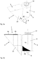
- the figure 1 shows a display device for a watch movement of a timepiece (not shown), according to one embodiment of the invention.
- the display device comprises in particular a roller 3 drivable in rotation around an axis of rotation 8 by a kinematic connection such as a gear train, the roller 3 comprising a pattern 4 on its periphery.
- the device also comprises at least one reflecting surface 5 arranged to project an image of the pattern 4 onto a projection surface 7, this surface preferably being substantially perpendicular to the axis of rotation 8.
- the pattern 4 varies. around the periphery of the roll 3 so that the visual appearance of the image 4 projected on the projection surface 7 varies according to the angular position of the roll 3 to change the indication of the display.
- the display device may indicate any relevant information of the timepiece such as the power reserve of the watch engine, the duration of a counter, an astronomical indication (for example, a day / night effect or the moon phase) or a status indication (for example the on / off status of an alarm clock or chrono or the position of a crown rod).
- the timepiece such as the power reserve of the watch engine, the duration of a counter, an astronomical indication (for example, a day / night effect or the moon phase) or a status indication (for example the on / off status of an alarm clock or chrono or the position of a crown rod).
- the device displays the power reserve and preferably comprises a rocket 1 intended to be kinematically coupled to a motor cylinder (not shown) of movement by the neck of a chain 2, so that the rocket 1 is pivoted when the engine cylinder is raised and when it discharges.
- the roller 3 is rotated by the rocket 1.
- the roller 3 is driven by the rocket 1 through a gear train 6 so that the roller 3 rotates in rotation.
- a given display angle ⁇ (which is typically at most 360 °, see FIG. figure 3a ) between the fully reassembled state and the fully discharged state of the engine cylinder spring.
- this surface 7 is substantially perpendicular to the axis of rotation 8
- the projected image then makes it possible to display the power reserve of the engine cylinder according to this embodiment.
- the use of the rocket 1 advantageously allows to constantly distribute the energy contained in the barrel as it discharges, but in variants the rocket can be removed.
- the rocket 1 is of generally frustoconical shape and provided with a helical groove (or ramp) 17 on which the chain 2 is wound.
- the chain may be replaced by a rope, or the like.
- the rocket can take other forms insofar as it can drive the roller 3 so that the latter rotates to indicate the power reserve of the engine cylinder.
- the reflecting surface 5 is a planar face of a right angle prism 10 disposed near the roller 3.
- the figure 2 illustrates a detail of the prism 10 and the roller 3 driven by the gear train 6.
- the gear train 6 comprises a rocket pinion 11 rotating with the rocket 1 and meshing with a succession of a first wheel 12 meshing with a second wheel 13 via a first pinion 12 '.
- the second wheel 13 meshes with a roller pinion 14, integral with the roller 3, through a second pinion 13 'integral with the second wheel 13.
- the diameter of the wheels 12, 13 and the ratio of the number of teeth on each of Wheels 12, 13 are adjusted so that the roller 3 is rotated by the given display angle ⁇ between the loaded and unloaded states of the engine cylinder.
- any other gear train or other means of kinematic cooperation between the rocket 1 and the roller 3 can be implemented to drive the roller 3 in rotation.
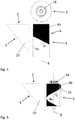
- the Figures 3a and 3b show a perspective view ( figure 3a ) a side view ( figure 3b ) of a portion of the power reserve display device, in which the prism 10 and the roller 3 are visible.
- the pattern 4 comprises a first clear area 4a and a second dark area 4b.
- the reflecting surface 5 of the prism 10 reflects the pattern 4 on the projection surface 7 which corresponds to the upper surface of the prism 10 and which is preferably parallel to the dial of the timepiece.
- the figure 4 shows an example of roller 3 in which the pattern 4 comprises a first clear area 4a and a second dark area 4b, the demarcation between the two areas 4a, 4b forming a straight line making an angle ⁇ with the axis of rotation 8 greater than 0 ° and less than 90 °.
- the image projected onto the projection surface 7 shows a proportion of the first zone (4a) clear more that increases relative to the second dark zone 4b.
- the pattern 4 can be arranged so that, in an initial angular position of the roll 3 which corresponds to the fully raised engine cylinder, the pattern 4 has only the second dark zone 4b with respect to the prism 10 and that the second zone 4b is gradually replaced by the first zone 4a clear as the engine cylinder discharges. In a final angular position of the roller 3 which corresponds to the fully discharged motor barrel, the pattern 4 has only the first zone 4a clear vis-à-vis the prism 10.
- the image projected on the projection surface 7 displays a dark bar (corresponding to the second zone 4b) indicating a maximum power reserve, when the engine cylinder is completely reassembled.
- the dark bar displayed on the projection surface 7 is gradually replaced by a light bar, in proportion with the residual power reserve, and a clear bar is displayed when the engine cylinder is completely discharged.
- the colors chosen for the first and second zones 4a and 4b are preferably such as to establish a good contrast between the two zones 4a and 4b.
- the first zone 4a visually differs from the second zone 4b, preferably, so that the two zones 4a, 4b are easily distinguishable from each other.
- the first area 4a may be of one color (such as red) and the second area 4b of another color (such as black). It is then possible to display on the projection surface 7 an entirely black strip when the watch (of the engine cylinder) is fully charged, the band filling up more and more red as the watch is discharged. .
- the demarcation between the first zone 4a and the second zone 4b is rather helical.
- the dividing line between the first and the second zone 4a, 4b forms any function whose slope of the tangent 15 forms an angle ⁇ with the axis of rotation 8 greater than 0 ° and smaller than 90 ° on at least a portion of the line.
- the image projected on the projection surface 7 displays the first and the second zone 4a, 4b in a proportion that varies continuously according to the angular position of the roller 3, and therefore of the power reserve in the illustrative example.
- the demarcation line separating the first and the second zone 4a, 4b moves on the projection surface 7 according to the angular position of the roll 3.
- the pattern 4 appearing on the periphery of the roll 3 is not limited to two visually distinct zones 4a, 4b, as in the examples above, but may take other forms. allowing the projected image on the projection surface 7 to display any indication.
- the pattern 4 may comprise a plurality of areas, each of the areas having a visual appearance that differs from other areas.
- the zones are arranged around the periphery of the roll 3 so that the visual appearance of the image 4 projected on the projection surface 7 varies according to the angular position of the roll.
- the reflecting surface 5 of the prism 10 makes an angle ⁇ of about 45 ° with the axis of rotation 8 of the roll 3 so as to project the image on the projection surface 7 substantially perpendicular to the axis of rotation 8.
- the angle ⁇ may be non-zero and smaller than 90 ° with the axis of rotation 8.
- the reflecting surface 5 may be formed of a plane mirror at an angle ⁇ with the axis of rotation 8 of the roller 3.
- the reflecting surface 5 may also be the face of a triangular prism.
- the reflecting surface 5 may comprise two reflective surfaces of a pentaprism.
- the image can be projected onto the projection surface 7 substantially perpendicular to the axis of rotation 8 of the roll 3.
- the F igures 6a to 6c represent the device for the power reserve display included in a watch movement, according to one embodiment.
- the movement is only partially visible.
- These elements are, for example, mounted on a plate 16 of the movement.
- the projection surface 7 is arranged substantially parallel to the plane of the plate.
- the movement may comprise a dial (not shown) so that the projection surface 7 is visible on the surface of the dial by example through a window (not shown) practiced in the dial or by transparency.
- figure 6a shows the power reserve display device when the engine cylinder is loaded.
- the chain 2 is completely wound on the rocket 1.
- the roller is in an initial angular position in which the image projected by the pattern 4 on the projection surface 7 displays a completely dark bar indicating a maximum power reserve.
- the figure 6b shows the power reserve display device when the engine cylinder is partially unloaded.
- the chain 2 unrolls the rocket 1 and gradually winds on the barrel by pulling on the rocket 1 with a lever arm continuously increasing so as to compensate for the reduction of the spring force of the barrel engine.
- the roller is in an intermediate angular position in which the image projected by the pattern 4 on the projection surface 7 displays a bar in dark part and partly clear, indicating an intermediate power reserve.
- the Figure 6c shows the power reserve display device when the engine cylinder is fully discharged.
- the chain 2 is completely unrolled from the rocket 1 and the roller is in a final angular position in which the image projected by the pattern 4 on the projection surface 7 displays a bar completely clear, indicating a zero power reserve.
- the device of the invention can be used for displays other than the power reserve poster.
- the roller 3 can be rotated by a display angle given by a kinematic connection so that the visual appearance of the image of the pattern 4 projected on the projection surface 7 varies according to the angular position of the roller 3 to change the indication of the display in the desired manner.
- the roller 3 can be kinematically linked to the engine cylinder other than via a rocket, for example by means of a gear train.
- the angular position of the roller can be controlled by the user, for example in the case of an indicator of the position of the crown rod.
- the roller 3 and the reflecting surface 5 can also be configured so that the projection surface 7 is located at a middle of a watch case comprising the movement or still at the bottom of the case.
Landscapes
- Physics & Mathematics (AREA)
- General Physics & Mathematics (AREA)
- Electromechanical Clocks (AREA)
Abstract
Description
- La présente invention se rapporte au domaine de l'horlogerie. Elle concerne, plus particulièrement, un mécanisme d'affichage pour une pièce d'horlogerie.
- Il est connu d'avoir un mécanisme d'affichage horloger mécanique où l'indicateur est constitué par un changement de motif, tel qu'un changement de teint ou de couleur, à la place d'un pointeur ou une aiguille.
- Par exemple, pour permettre aux porteurs de montre comportant un mouvement mécanique de se rendre compte de l'état de tension du ressort moteur d'un ou plusieurs barillets moteurs, il existe des constructions dans lesquelles un mécanisme différentiel commandé, d'une part, par l'arbre du barillet et, d'autre part, par le tambour du barillet, est destiné à déplacer une aiguille au-dessus d'une graduation du cadran ou un disque gradué dans un guichet du cadran. Que cet organe mobile soit un disque placé sous le cadran ou une aiguille se déplaçant au-dessus du cadran, le mécanisme différentiel destiné à le commander est agencé de façon que cet organe indicateur mobile occupe, par rapport au cadran, une position angulaire extrême déterminée quand le ressort moteur de la montre est complètement armé et une autre position angulaire extrême déterminée quand le ressort est désarmé.
- Même en utilisant un disque mobile sous le cadran, il faut prévoir un guichet qui occupe une place relativement importante du cadran sinon les graduations du disque ne seront plus lisibles.
- Le document
CH336760 - Le document
EP2869137 décrit un mécanisme indicateur de réserve de marche, notamment pour pièce d'horlogerie avec une fusée, comprenant un axe fileté destiné à être monté solidaire à un élément de bâti de la pièce d'horlogerie, une came présentant une surface extérieure inclinée par rapport à l'axe et agencée pour coopérer par vissage avec l'axe fileté, un mobile entraîneur de la came destiné à être mis en rotation dans les deux sens de rotation au moyen d'un barillet, et un palpeur en contact avec la surface extérieure de la came et en liaison cinématique avec un indicateur de réserve de marche. - La présente invention concerne un dispositif d'affichage pour un mouvement de montre, le dispositif comprenant un rouleau entraînable en rotation atour d'une axe de rotation par un train de rouages et comprenant un motif sur son pourtour; et au moins une surface réfléchissante arrangée de manière à projeter une image du motif sur une surface de projection, le motif variant sur le pourtour du rouleau de manière à ce que l'aspect visuel de l'image du motif projetée sur la surface de projection varie selon la position angulaire du rouleau.
- Dans un mode de réalisation, le rouleau est entraîné en rotation par un barillet moteur du mouvement par un train de rouages configuré pour coupler cinématiquement le barillet moteur avec le rouleau.
- Dans un mode de réalisation, le dispositif comprend une fusée qui est cinématiquement couplée au barillet moteur de sorte à ce que la fusée est entraînée en pivotement lorsque le barillet moteur est remonté et lorsqu'il se décharge et à ce que le rouleau est entraîné en rotation par la fusée.
- Selon une forme d'exécution, la durée prédéterminée correspond à la réserve de marche du barillet moteur, de sorte à afficher la réserve de marche du barillet moteur.
- L'invention concerne également un mouvement de montre comprenant le dispositif. Le mouvement peut comprendre un cadran, et la surface réfléchissante peut être configurée pour que la surface de projection soit visible à la surface du cadran.
- La présente invention concerne un mécanisme d'affichage de type « barre » comprenant un prisme et un rouleau « bicolore » faisant partie d'une chaine cinématique lié au barillet.
- Le dispositif d'affichage de l'invention présente notamment l'avantage par rapport à l'art antérieur de permettre d'afficher une indication par le biais d'un changement de motif qui occupe très peu de place, par exemple sur la surface d'un cadran.
- Des exemples de mise en oeuvre de l'invention sont indiqués dans la description illustrée par les figures annexées dans lesquelles :
- la
figure 1 montre un dispositif d'affichage de réserve de marche pour un mouvement de montre mécanique, selon un mode de réalisation; - la
figure 2 illustre un détail du dispositif d'affichage, selon un mode de réalisation; - Les
figures 3a et 3b montrent une vue en perspective (figure 3a ) une vue de côté (figure 3b ) d'un rouleau et d'un prisme d'affichage de réserve de marche, selon un mode de réalisation; - la
figure 4 montre un motif du rouleau, selon un mode de réalisation; - la
figure 5 montre un motif du rouleau, selon un autre mode de réalisation; et - les
figures 6a à 6c montrent le dispositif d'affichage de réserve de marche lorsque le barillet moteur est chargé (figure 6a ), partiellement déchargé (figure 6b ) et complètement déchargé (figure 6c ), selon un mode de réalisation. - La
figure 1 montre un dispositif d'affichage pour un mouvement de montre d'une pièce d'horlogerie(non représenté), selon un mode de réalisation de l'invention. Le dispositif d'affichage comprend notamment un rouleau 3 entraînable en rotation atour d'une axe de rotation 8 par une liaison cinématique tel qu'un train de rouages, le rouleau 3 comprenant un motif 4 sur son pourtour. Le dispositif comprend également au moins une surface réfléchissante 5 arrangée de manière à projeter une image du motif 4 sur une surface de projection 7, cette surface étant de préférence substantiellement perpendiculaire à l'axe de rotation 8. De cette manière, le motif 4 varie sur le pourtour du rouleau 3 de manière à ce que l'aspect visuel de l'image 4 projetée sur la surface de projection 7 varie selon la position angulaire du rouleau 3 pour changer l'indication de l'affichage. - Le dispositif d'affichage peut indiquer n'importante quelle information pertinente de la pièce d'horlogerie telle que la réserve de marche du moteur horloger, la durée d'un compteur, une indication astronomique (par exemple, un effet jour/nuit ou la phase de lune) ou une indication d'état (par exemple l'état on/off d'un réveil ou d'un chrono ou la position d'une tige de couronne).
- Dans le mode de réalisation de la
figure 1 , le dispositif affiche la réserve de marche et comprend de préférence une fusée 1 destinée à être cinématiquement couplée à un barillet moteur (non représenté) du mouvement par le bais d'une chaine 2, de sorte à ce que la fusée 1 soit entraînée en pivotement lorsque le barillet moteur est remonté et lorsqu'il se décharge. Dans ce mode, le rouleau 3 est entraîné en rotation par la fusée 1. En particulier, le rouleau 3 est entraîné par la fusée 1 par le biais d'un train de rouages 6 de manière à ce que le rouleau 3 tourne en rotation d'un angle d'affichage donné β (qui est typiquement au maximum 360°, voir lafigure 3a ) entre l'état entièrement remonté et l'état entièrement déchargé du ressort du barillet moteur. La surface réfléchissante 5 qui de préférence fait partie d'un prisme 10, est disposée de manière à réfléchir le motif 4 du rouleau 3 sur une surface de projection 7. De préférence, cette surface 7 est substantiellement perpendiculaire à l'axe de rotation 8 du rouleau 3. L'image projetée permet alors d'afficher la réserve de marche du barillet moteur selon ce mode de réalisation. - L'utilisation de la fusée 1 permet avantageusement de distribuer de façon constante l'énergie contenue dans le barillet au fur et à mesure que ce dernier se décharge, mais dans des variantes la fusée peut être supprimée. La fusée 1 est de forme généralement tronconique et munie d'une rainure (or rampe) hélicoïdale 17 sur laquelle s'enroule la chaine 2. La chaine peut être remplacée par une corde, ou similaire. La fusée peut prendre d'autres formes dans la mesure où elle peut entrainer le rouleau 3 de manière à ce que ce dernier tourne en rotation pour indiquer la réserve de marche du barillet moteur.
- Dans la forme d'exécution montrée à la
figure 1 , la surface réfléchissante 5 est une face plane d'un prisme 10 à angle droit, disposé à proximité du rouleau 3. - La
figure 2 illustre un détail du prisme 10 et du rouleau 3 entraîné par le train de rouages 6. Dans cet exemple, le train de rouages 6 comprend un pignon de fusée 11 tournant avec la fusée 1 et engrenant avec une succession d'une première roue 12 engrenant avec une seconde roue 13 par l'intermédiaire d'un premier pignon 12'. La seconde roue 13 engrène avec un pignon de rouleau 14, solidaire du rouleau 3, par le biais d'un second pignon 13' solidaire de la seconde roue 13. Le diamètre des roues 12, 13 ainsi que le rapport du nombre des dents sur chacune des roues 12,13 sont ajustés de manière à ce que le rouleau 3 soit entraîné en rotation par l'angle d'affichage donné β entre les états chargé et déchargé du barillet moteur. On comprendra que tout autre trains de rouages ou autre moyens de coopération cinématique entre la fusée 1 et le rouleau 3 peuvent être mis en oeuvre pour entraîner le rouleau 3 en rotation. - Les
figures 3a et 3b montrent une vue en perspective (figure 3a ) une vue de côté (figure 3b ) d'une partie du dispositif d'affichage de réserve de marche, dans laquelle le prisme 10 et le rouleau 3 sont visibles. Dans l'exemple illustré auxfigures 3a et 3b , le motif 4 comprend une première zone 4a claire et une seconde zone 4b foncée. La surface réfléchissante 5 du prisme 10 réfléchie le motif 4 sur la surface de projection 7 qui correspond à la surface supérieure du prisme 10 et qui est de préférence parallèle au cadran de la pièce d'horlogerie. - La
figure 4 montre un exemple de rouleau 3 dans lequel le motif 4 comprend une première zone 4a claire et une seconde zone 4b foncée, la démarcation entre les deux zones 4a, 4b formant une ligne droite faisant un angle θ avec l'axe de rotation 8 plus grand que 0° et plus petit que 90°. De la sorte, lors de la rotation du rouleau 3, l'image projetée sur la surface de projection 7 montre une proportion de la première zone (4a) claire de plus qui augmente par rapport à la seconde zone 4b foncée. En particulier, le motif 4 peut être arrangé pour que, dans une position angulaire initiale du rouleau 3 qui correspond au barillet moteur complètement remonté, le motif 4 ne présente que la seconde zone 4b foncée vis-à-vis du prisme 10 et que la seconde zone 4b soit graduellement remplacée par la première zone 4a claire à mesure que le barillet moteur se décharge. Dans une position angulaire finale du rouleau 3 qui correspond au barillet moteur complètement déchargé, le motif 4 ne présente que la première zone 4a claire vis-à-vis du prisme 10. - De la sorte, l'image projetée sur la surface de projection 7 affiche une barre foncée (correspondant à la seconde zone 4b) indiquant une réserve de marche maximale, lorsque le barillet moteur est complètement remonté. A mesure que le barillet moteur se décharge, la barre foncée affichée sur la surface de projection 7 est graduellement remplacée par une barre claire, en proportion avec la réserve de marche résiduelle, et une barre claire est affichée lorsque le barillet moteur est complètement déchargé.
- Les teintes choisies pour les première et seconde zones 4a et 4b sont de préférence telles à établir un bon contraste entre les deux zones 4a et 4b. De manière générale, la première zone 4a diffère visuellement de la seconde zone 4b, préférablement, de sorte à ce que les deux zones 4a, 4b soient facilement distinguable l'une de l'autre. Par exemple, la première zone 4a peut être d'une couleur (tel que le rouge) et la seconde zone 4b d'une autre couleur (tel que le noir). Il est alors possible d'afficher sur la surface de projection 7 une bande entièrement noire lorsque la montre (du barillet moteur) est complètement chargée, la bande se remplissant de plus en plus de rouge au fur et à mesure de la décharge de la montre.
- Selon la forme d'exécution montrée à la
figure 5 , la démarcation entre la première zone 4a et la seconde zone 4b a plutôt une forme hélicoïdale . De manière générale, la ligne de démarcation entre la première et la seconde zone 4a, 4b forme une fonction quelconque dont la pente de la tangente 15 forme un angle θ avec l'axe de rotation 8 plus grand que 0° et plus petit que 90° sur au moins une portion de la ligne. De la sorte, l'image projetée sur la surface de projection 7 affiche la première et la seconde zone 4a, 4b dans une proportion qui varie de manière continue selon la position angulaire du rouleau 3, et donc de la réserve de marche dans l'exemple illustratif. - La ligne de démarcation séparant la première et la seconde zone 4a, 4b se déplace sur la surface de projection 7 selon la position angulaire du rouleau 3.
- On comprendra que le motif 4 apparaissant sur le pourtour du rouleau 3 n'est pas limité à deux zones 4a, 4b visuellement distinctes comme dans les exemples ci-dessus mais peut prendre d'autres formes permettant à l'image projetée sur la surface de projection 7 d'afficher une indication quelconque.
- Par exemple, le motif 4 peut comprendre une pluralité de zones, chacune des zones ayant un aspect visuel qui diffère des autres zones. Les zones sont arrangées sur le pourtour du rouleau 3 de manière à ce que l'aspect visuel de l'image 4 projetée sur la surface de projection 7 varie selon la position angulaire du rouleau.
- De manière préférée, la surface réfléchissante 5 du prisme 10 fait un angle α d'environ 45° avec l'axe de rotation 8 du rouleau 3 se sorte à projeter l'image sur la surface de projection 7 sensiblement perpendiculaire à l'axe de rotation 8. Alternativement, l'angle α peut être non nul et plus petit que 90° avec l'axe de rotation 8.
- D'autres configurations sont également possibles. Par exemple, la surface réfléchissante 5 peut être formée d'un miroir plan faisant un angle α avec l'axe de rotation 8 du rouleau 3. La surface réfléchissante 5 peut également être la face d'un prisme à base triangulaire. La surface réfléchissante 5 peut comprendre deux surfaces réfléchissante d'un pentaprisme. Ainsi, l'image peut être projetée sur la surface de projection 7 sensiblement perpendiculaire avec l'axe de rotation 8 du rouleau 3.
- Les f
igures 6a à 6c représentent le dispositif pour l'affichage de réserve de marche compris dans un mouvement de montre, selon un mode de réalisation. Dans lesfigures 6a à 6c , le mouvement n'est que partiellement visible. On voit néanmoins la fusée 1 entraînant le rouleau 3 par l'intermédiaire du train de rouages 6, ainsi que le prisme 10 et la surface de projection 7. Ces éléments sont, par exemple, montés sur une platine 16 du mouvement. La surface de projection 7 est arrangée sensiblement parallèle au plan de la platine. - Le mouvement peut comprendre un cadran (non représenté) de sorte que la surface de projection 7 est visible à la surface du cadran, par exemple au travers d'un guichet (non représenté) pratiqué dans le cadran ou par transparence.
- En particulier, la
figure 6a montre le dispositif d'affichage de réserve de marche lorsque le barillet moteur est chargé. La chaine 2 est complètement enroulée sur la fusée 1. Le rouleau est dans une position angulaire initiale dans laquelle l'image projetée par le motif 4 sur la surface de projection 7 affiche une barre complètement foncée indiquant une réserve de marche maximale. - La
figure 6b montre le dispositif d'affichage de réserve de marche lorsque le barillet moteur est partiellement déchargé. Lors du désarmage du ressort moteur, la chaîne 2 se déroule de la fusée 1 et s'enroule progressivement sur le barillet en tirant sur la fusée 1 avec un bras de levier continuellement croissant de manière à compenser la réduction de la force du ressort du barillet moteur. Le rouleau est dans une position angulaire intermédiaire dans laquelle l'image projetée par le motif 4 sur la surface de projection 7 affiche une barre en partie foncée et en partie claire, indiquant une réserve de marche intermédiaire. - La
figure 6c montre le dispositif d'affichage de réserve de marche lorsque le barillet moteur est complètement déchargé. La chaîne 2 est complètement déroulée de la fusée 1 et le rouleau est dans une position angulaire finale dans laquelle l'image projetée par le motif 4 sur la surface de projection 7 affiche une barre complètement claire, indiquant une réserve de marche nulle. - Il va de soi que la présente invention n'est pas limitée au mode de réalisation qui vient d'être décrit et que diverses modifications et variantes simples peuvent être envisagées par l'homme de métier sans sortir du cadre de la présente invention.
- En effet, le dispositif de l'invention peut être utilisé pour des affichages autres que l'affiche de réserve de marche. A cette fin, le rouleau 3 peut être entrainé en rotation d'un angle d'affichage donné par une liaison cinématique de manière à ce que l'aspect visuel de l'image du motif 4 projetée sur la surface de projection 7 varie selon la position angulaire du rouleau 3 pour changer l'indication de l'affichage dans la manière voulue.
- D'autre part, le rouleau 3 peut être lié cinématiquement au barillet moteur autrement que par l'intermédiaire d'une fusée, par exemple par l'intermédiaire d'un train de rouage. Dans d'autres formes d'exécution la position angulaire du rouleau peut être commandée par l'utilisateur, par exemple dans le cas d'un indicateur de la position de la tige de couronne.
- Le rouleau 3 et la surface réfléchissante 5 (fournie par un prisme ou un autre arrangement) peuvent également être configurés de manière à ce que la surface de projection 7 soit localisée au niveau d'une carrure d'un boitier de montre comprenant le mouvement ou encore au niveau du fond du boitier.
-
- 1
- fusée
- 2
- chaine
- 3
- rouleau
- 4
- motif
- 5
- surface réfléchissante
- 6
- train de rouages
- 7
- surface de projection
- 8
- axe de rotation
- 9
- image
- 10
- prisme
- 11
- pignon de fusée
- 12
- première roue
- 12'
- premier pignon
- 13
- seconde roue
- 13'
- second pignon
- 14
- pignon de rouleau
- 15
- tangente
- 16
- platine
- 17
- rainure hélicoïdale
- α
- angle
- β
- angle
- θ
- angle
Claims (14)
- Dispositif d'affichage pour un mouvement de montre, le dispositif comprenant:un rouleau (3) entraînable en rotation atour d'une axe de rotation (8) par un train de rouages et comprenant un motif (4) sur son pourtour; etau moins une surface réfléchissante (5) arrangée de manière à projeter une image du motif (4) sur une surface de projection (7),le motif (4) variant sur le pourtour du rouleau (3) de manière à ce que l'aspect visuel de l'image du motif (4) projetée sur la surface de projection (7) varie selon la position angulaire du rouleau (3).
- Le dispositif selon la revendication 1,
le rouleau (3) étant entraîné en rotation par un barillet moteur du mouvement par un train de rouages configuré pour coupler cinématiquement le barillet moteur avec le rouleau (3). - Le dispositif selon la revendication 2,
comprenant une fusée (1) destinée à être cinématiquement couplée au barillet moteur de sorte à ce que la fusée (1) soit entraînée en pivotement lorsque le barillet moteur est remonté et lorsqu'il se décharge, le rouleau (3) étant entraîné en rotation par la fusée (1). - Le dispositif selon la revendication 3,
comprenant en outre un train de rouages (6) entre la fusée (1) et le rouleau (3) de manière à ce que le rouleau (3) tourne en rotation d'un angle d'affichage donné entre l'état entièrement remonté et l'état entièrement déchargé du ressort du barillet moteur. - Le dispositif selon l'une des revendications 1 à 4,
dans lequel à le dispositif affiche la réserve de marche du barillet moteur. - Le dispositif selon l'une des revendications 1 à 5,
dans lequel le motif (4) comprend une pluralité de zones (4a, 4b), chacune des zones ayant un aspect visuel qui diffère des autres zones. - Le dispositif selon la revendication 6,
dans lequel le motif (4) comprend une première zone (4a) et une seconde zone (4b) d'aspect visuel différent de celui de la première zone (4a) de sorte que la proportion visible de la première zone (4a) et de la seconde zone (4b) sur la surface (7) change selon la position angulaire du rouleau (3). - Le dispositif selon la revendication 7,
dans lequel une ligne de démarcation entre la première et la seconde zone (4a, 4b) forme une ligne droite faisant un angle (θ) avec l'axe de rotation (8) plus grand que 0° et plus petit que 90°. - Le dispositif selon la revendication 7,
dans lequel une ligne de démarcation entre la première et la seconde zone (4a, 4b) forme une fonction quelconque dont la pente de la tangente forme un angle (θ) avec l'axe de rotation (8) plus grand que 0° et plus petit que 90° sur au moins une portion de la ligne. - Le dispositif selon l'une des revendications 1 à 9,
dans lequel ladite au moins une surface réfléchissante (5) comprend une face plane d'un prisme (10). - Le dispositif selon l'une des revendications 1 à 10,
dans lequel ladite surface de projection (7) est substantiellement perpendiculaire à l'axe de rotation (8) du rouleau (3). - Pièce d'horlogerie comprenant le dispositif selon l'une des revendications 1 à 11.
- La pièce d'horlogerie selon la revendication 12,
comprenant un cadran, ladite au moins une surface réfléchissante (5) étant configurée pour que la surface de projection (7) soit visible à la surface du cadran. - La pièce d'horlogerie selon la revendication 13,
dans lequel la surface de projection (7) apparaît au travers d'un guichet pratiqué dans le cadran.
Applications Claiming Priority (1)
| Application Number | Priority Date | Filing Date | Title |
|---|---|---|---|
| CH00214/17A CH713484A1 (fr) | 2017-02-24 | 2017-02-24 | Dispositif d'affichage pour un mouvement de montre, notamment d'affichage de réserve de marche. |
Publications (2)
| Publication Number | Publication Date |
|---|---|
| EP3367181A1 true EP3367181A1 (fr) | 2018-08-29 |
| EP3367181B1 EP3367181B1 (fr) | 2019-10-02 |
Family
ID=58212862
Family Applications (1)
| Application Number | Title | Priority Date | Filing Date |
|---|---|---|---|
| EP18157996.2A Active EP3367181B1 (fr) | 2017-02-24 | 2018-02-22 | Dispositif d'affichage de réserve de marche |
Country Status (2)
| Country | Link |
|---|---|
| EP (1) | EP3367181B1 (fr) |
| CH (1) | CH713484A1 (fr) |
Citations (7)
| Publication number | Priority date | Publication date | Assignee | Title |
|---|---|---|---|---|
| DE1377059U (fr) * | ||||
| CH336760A (fr) * | 1957-02-22 | 1959-02-28 | Schild Sa A | Dispositif indicateur de réserve de marche |
| US3587222A (en) * | 1969-06-20 | 1971-06-28 | Robert Mestrovic | Linear clock |
| WO2007107204A2 (fr) * | 2006-03-17 | 2007-09-27 | Marblia Ltd. | Module de base pour piece d'horlogerie, notamment montre-bracelet |
| WO2012134411A1 (fr) * | 2011-04-01 | 2012-10-04 | Yildirim Cuma Evren | Cadran de montre à réflexion de miroir |
| CH705336B1 (fr) * | 2007-09-01 | 2013-02-15 | Christophe Claret Sa | Mécanisme d'affichage des phases de lune. |
| CH706209A2 (fr) * | 2012-03-07 | 2013-09-13 | Montres Romain Gauthier Sa | Mouvement de montre comprenant un barillet à couple constant. |
-
2017
- 2017-02-24 CH CH00214/17A patent/CH713484A1/fr not_active Application Discontinuation
-
2018
- 2018-02-22 EP EP18157996.2A patent/EP3367181B1/fr active Active
Patent Citations (7)
| Publication number | Priority date | Publication date | Assignee | Title |
|---|---|---|---|---|
| DE1377059U (fr) * | ||||
| CH336760A (fr) * | 1957-02-22 | 1959-02-28 | Schild Sa A | Dispositif indicateur de réserve de marche |
| US3587222A (en) * | 1969-06-20 | 1971-06-28 | Robert Mestrovic | Linear clock |
| WO2007107204A2 (fr) * | 2006-03-17 | 2007-09-27 | Marblia Ltd. | Module de base pour piece d'horlogerie, notamment montre-bracelet |
| CH705336B1 (fr) * | 2007-09-01 | 2013-02-15 | Christophe Claret Sa | Mécanisme d'affichage des phases de lune. |
| WO2012134411A1 (fr) * | 2011-04-01 | 2012-10-04 | Yildirim Cuma Evren | Cadran de montre à réflexion de miroir |
| CH706209A2 (fr) * | 2012-03-07 | 2013-09-13 | Montres Romain Gauthier Sa | Mouvement de montre comprenant un barillet à couple constant. |
Also Published As
| Publication number | Publication date |
|---|---|
| CH713484A1 (fr) | 2018-08-31 |
| EP3367181B1 (fr) | 2019-10-02 |
Similar Documents
| Publication | Publication Date | Title |
|---|---|---|
| EP2360535B1 (fr) | Masse oscillante pour montre à remontage automatique, comportant un dispositif indicateur de la réserve de marche intégré dans ladite masse oscillante | |
| EP3267267B1 (fr) | Mécanisme d'affichage de phase de lune | |
| EP3627240B1 (fr) | Mécanisme d'affichage à rouleau pour montre | |
| WO2007110446A2 (fr) | Piece d'horlogerie a affichage par ruban | |
| WO2014095728A1 (fr) | Piece d'horlogerie a affichage de l'heure universelle | |
| CH699276B1 (fr) | Pièce d'horlogerie comportant un mécanisme de remontage automatique. | |
| EP3570119B1 (fr) | Mecanisme d'affichage d'un evenement periodique et piece d'horlogerie comportant un tel mecanisme | |
| CH703361A2 (fr) | Mouvement horloger presentant des fonctions de chronographe et de compte-a-rebours. | |
| EP3367181B1 (fr) | Dispositif d'affichage de réserve de marche | |
| WO2014177290A1 (fr) | Piece d'horlogerie comprenant un dispositif d'affichage de quantieme | |
| EP3696617A1 (fr) | Mecanisme d'affichage de mois et d'annee bissextile pour piece d'horlogerie | |
| CH700958A2 (fr) | Montre a mouvement mobile. | |
| EP3629101B1 (fr) | Mécanisme d'affichage horloger | |
| EP1612625B1 (fr) | Mécanisme indicateur de la réserve de marche d'une montre mécanique | |
| EP0504623A1 (fr) | Double fuseau horaire à axe traversant avec mise à l'heure sur la couronne | |
| CH715842A2 (fr) | Mécanisme d'affichage de mois et d'année bissextile pour pièce d'horlogerie. | |
| WO2024178518A1 (fr) | Dispositif d'affichage de réserve de marche pour pièce d'horlogerie | |
| EP3769159B1 (fr) | Système horloger de transmission | |
| EP0509403A1 (fr) | Mouvement d'horlogerie | |
| CH721836A2 (fr) | Mécanisme indicateur de la réserve de marche agencé pour éviter un désindexage | |
| EP2254007B1 (fr) | Dispositif d'affichage de la réserve de marche pour une pièce d'horlogerie | |
| CH711593B1 (fr) | Dispositif d'affichage et pièce d'horlogerie comportant un tel dispositif d'affichage | |
| CH700744A1 (fr) | Ruban sans fin et piece d'horlogerie a affichage par un tel ruban. | |
| CH705336B1 (fr) | Mécanisme d'affichage des phases de lune. | |
| CH717539B1 (fr) | Mécanisme d'affichage horloger rétrograde de type traînant équipé d'une bascule de débrayage de l'affichage. |
Legal Events
| Date | Code | Title | Description |
|---|---|---|---|
| PUAI | Public reference made under article 153(3) epc to a published international application that has entered the european phase |
Free format text: ORIGINAL CODE: 0009012 |
|
| STAA | Information on the status of an ep patent application or granted ep patent |
Free format text: STATUS: THE APPLICATION HAS BEEN PUBLISHED |
|
| AK | Designated contracting states |
Kind code of ref document: A1 Designated state(s): AL AT BE BG CH CY CZ DE DK EE ES FI FR GB GR HR HU IE IS IT LI LT LU LV MC MK MT NL NO PL PT RO RS SE SI SK SM TR |
|
| AX | Request for extension of the european patent |
Extension state: BA ME |
|
| STAA | Information on the status of an ep patent application or granted ep patent |
Free format text: STATUS: REQUEST FOR EXAMINATION WAS MADE |
|
| 17P | Request for examination filed |
Effective date: 20190206 |
|
| RBV | Designated contracting states (corrected) |
Designated state(s): AL AT BE BG CH CY CZ DE DK EE ES FI FR GB GR HR HU IE IS IT LI LT LU LV MC MK MT NL NO PL PT RO RS SE SI SK SM TR |
|
| GRAP | Despatch of communication of intention to grant a patent |
Free format text: ORIGINAL CODE: EPIDOSNIGR1 |
|
| STAA | Information on the status of an ep patent application or granted ep patent |
Free format text: STATUS: GRANT OF PATENT IS INTENDED |
|
| RIC1 | Information provided on ipc code assigned before grant |
Ipc: G04B 19/21 20060101ALI20190328BHEP Ipc: G04B 9/00 20060101AFI20190328BHEP |
|
| INTG | Intention to grant announced |
Effective date: 20190424 |
|
| RIN1 | Information on inventor provided before grant (corrected) |
Inventor name: HOURIET, ARNAUD Inventor name: RANERI, GIONATAN Inventor name: CASSE, ARNAUD Inventor name: DREYER-GONZALES, FREDERIC |
|
| GRAS | Grant fee paid |
Free format text: ORIGINAL CODE: EPIDOSNIGR3 |
|
| GRAA | (expected) grant |
Free format text: ORIGINAL CODE: 0009210 |
|
| STAA | Information on the status of an ep patent application or granted ep patent |
Free format text: STATUS: THE PATENT HAS BEEN GRANTED |
|
| AK | Designated contracting states |
Kind code of ref document: B1 Designated state(s): AL AT BE BG CH CY CZ DE DK EE ES FI FR GB GR HR HU IE IS IT LI LT LU LV MC MK MT NL NO PL PT RO RS SE SI SK SM TR |
|
| REG | Reference to a national code |
Ref country code: GB Ref legal event code: FG4D Free format text: NOT ENGLISH |
|
| REG | Reference to a national code |
Ref country code: CH Ref legal event code: EP Ref country code: CH Ref legal event code: NV Representative=s name: P&TS SA, CH Ref country code: AT Ref legal event code: REF Ref document number: 1186877 Country of ref document: AT Kind code of ref document: T Effective date: 20191015 |
|
| REG | Reference to a national code |
Ref country code: DE Ref legal event code: R096 Ref document number: 602018000748 Country of ref document: DE |
|
| REG | Reference to a national code |
Ref country code: IE Ref legal event code: FG4D Free format text: LANGUAGE OF EP DOCUMENT: FRENCH |
|
| REG | Reference to a national code |
Ref country code: NL Ref legal event code: MP Effective date: 20191002 |
|
| REG | Reference to a national code |
Ref country code: LT Ref legal event code: MG4D |
|
| REG | Reference to a national code |
Ref country code: AT Ref legal event code: MK05 Ref document number: 1186877 Country of ref document: AT Kind code of ref document: T Effective date: 20191002 |
|
| PG25 | Lapsed in a contracting state [announced via postgrant information from national office to epo] |
Ref country code: LT Free format text: LAPSE BECAUSE OF FAILURE TO SUBMIT A TRANSLATION OF THE DESCRIPTION OR TO PAY THE FEE WITHIN THE PRESCRIBED TIME-LIMIT Effective date: 20191002 Ref country code: PL Free format text: LAPSE BECAUSE OF FAILURE TO SUBMIT A TRANSLATION OF THE DESCRIPTION OR TO PAY THE FEE WITHIN THE PRESCRIBED TIME-LIMIT Effective date: 20191002 Ref country code: GR Free format text: LAPSE BECAUSE OF FAILURE TO SUBMIT A TRANSLATION OF THE DESCRIPTION OR TO PAY THE FEE WITHIN THE PRESCRIBED TIME-LIMIT Effective date: 20200103 Ref country code: NO Free format text: LAPSE BECAUSE OF FAILURE TO SUBMIT A TRANSLATION OF THE DESCRIPTION OR TO PAY THE FEE WITHIN THE PRESCRIBED TIME-LIMIT Effective date: 20200102 Ref country code: AT Free format text: LAPSE BECAUSE OF FAILURE TO SUBMIT A TRANSLATION OF THE DESCRIPTION OR TO PAY THE FEE WITHIN THE PRESCRIBED TIME-LIMIT Effective date: 20191002 Ref country code: SE Free format text: LAPSE BECAUSE OF FAILURE TO SUBMIT A TRANSLATION OF THE DESCRIPTION OR TO PAY THE FEE WITHIN THE PRESCRIBED TIME-LIMIT Effective date: 20191002 Ref country code: LV Free format text: LAPSE BECAUSE OF FAILURE TO SUBMIT A TRANSLATION OF THE DESCRIPTION OR TO PAY THE FEE WITHIN THE PRESCRIBED TIME-LIMIT Effective date: 20191002 Ref country code: BG Free format text: LAPSE BECAUSE OF FAILURE TO SUBMIT A TRANSLATION OF THE DESCRIPTION OR TO PAY THE FEE WITHIN THE PRESCRIBED TIME-LIMIT Effective date: 20200102 Ref country code: PT Free format text: LAPSE BECAUSE OF FAILURE TO SUBMIT A TRANSLATION OF THE DESCRIPTION OR TO PAY THE FEE WITHIN THE PRESCRIBED TIME-LIMIT Effective date: 20200203 Ref country code: FI Free format text: LAPSE BECAUSE OF FAILURE TO SUBMIT A TRANSLATION OF THE DESCRIPTION OR TO PAY THE FEE WITHIN THE PRESCRIBED TIME-LIMIT Effective date: 20191002 Ref country code: ES Free format text: LAPSE BECAUSE OF FAILURE TO SUBMIT A TRANSLATION OF THE DESCRIPTION OR TO PAY THE FEE WITHIN THE PRESCRIBED TIME-LIMIT Effective date: 20191002 Ref country code: NL Free format text: LAPSE BECAUSE OF FAILURE TO SUBMIT A TRANSLATION OF THE DESCRIPTION OR TO PAY THE FEE WITHIN THE PRESCRIBED TIME-LIMIT Effective date: 20191002 |
|
| PG25 | Lapsed in a contracting state [announced via postgrant information from national office to epo] |
Ref country code: IS Free format text: LAPSE BECAUSE OF FAILURE TO SUBMIT A TRANSLATION OF THE DESCRIPTION OR TO PAY THE FEE WITHIN THE PRESCRIBED TIME-LIMIT Effective date: 20200224 Ref country code: CZ Free format text: LAPSE BECAUSE OF FAILURE TO SUBMIT A TRANSLATION OF THE DESCRIPTION OR TO PAY THE FEE WITHIN THE PRESCRIBED TIME-LIMIT Effective date: 20191002 Ref country code: HR Free format text: LAPSE BECAUSE OF FAILURE TO SUBMIT A TRANSLATION OF THE DESCRIPTION OR TO PAY THE FEE WITHIN THE PRESCRIBED TIME-LIMIT Effective date: 20191002 Ref country code: RS Free format text: LAPSE BECAUSE OF FAILURE TO SUBMIT A TRANSLATION OF THE DESCRIPTION OR TO PAY THE FEE WITHIN THE PRESCRIBED TIME-LIMIT Effective date: 20191002 |
|
| PG25 | Lapsed in a contracting state [announced via postgrant information from national office to epo] |
Ref country code: AL Free format text: LAPSE BECAUSE OF FAILURE TO SUBMIT A TRANSLATION OF THE DESCRIPTION OR TO PAY THE FEE WITHIN THE PRESCRIBED TIME-LIMIT Effective date: 20191002 |
|
| REG | Reference to a national code |
Ref country code: DE Ref legal event code: R097 Ref document number: 602018000748 Country of ref document: DE |
|
| PG2D | Information on lapse in contracting state deleted |
Ref country code: IS |
|
| PG25 | Lapsed in a contracting state [announced via postgrant information from national office to epo] |
Ref country code: RO Free format text: LAPSE BECAUSE OF FAILURE TO SUBMIT A TRANSLATION OF THE DESCRIPTION OR TO PAY THE FEE WITHIN THE PRESCRIBED TIME-LIMIT Effective date: 20191002 Ref country code: EE Free format text: LAPSE BECAUSE OF FAILURE TO SUBMIT A TRANSLATION OF THE DESCRIPTION OR TO PAY THE FEE WITHIN THE PRESCRIBED TIME-LIMIT Effective date: 20191002 Ref country code: DK Free format text: LAPSE BECAUSE OF FAILURE TO SUBMIT A TRANSLATION OF THE DESCRIPTION OR TO PAY THE FEE WITHIN THE PRESCRIBED TIME-LIMIT Effective date: 20191002 Ref country code: IS Free format text: LAPSE BECAUSE OF FAILURE TO SUBMIT A TRANSLATION OF THE DESCRIPTION OR TO PAY THE FEE WITHIN THE PRESCRIBED TIME-LIMIT Effective date: 20200202 |
|
| PLBE | No opposition filed within time limit |
Free format text: ORIGINAL CODE: 0009261 |
|
| STAA | Information on the status of an ep patent application or granted ep patent |
Free format text: STATUS: NO OPPOSITION FILED WITHIN TIME LIMIT |
|
| PG25 | Lapsed in a contracting state [announced via postgrant information from national office to epo] |
Ref country code: SM Free format text: LAPSE BECAUSE OF FAILURE TO SUBMIT A TRANSLATION OF THE DESCRIPTION OR TO PAY THE FEE WITHIN THE PRESCRIBED TIME-LIMIT Effective date: 20191002 Ref country code: SK Free format text: LAPSE BECAUSE OF FAILURE TO SUBMIT A TRANSLATION OF THE DESCRIPTION OR TO PAY THE FEE WITHIN THE PRESCRIBED TIME-LIMIT Effective date: 20191002 |
|
| 26N | No opposition filed |
Effective date: 20200703 |
|
| REG | Reference to a national code |
Ref country code: BE Ref legal event code: MM Effective date: 20200229 |
|
| PG25 | Lapsed in a contracting state [announced via postgrant information from national office to epo] |
Ref country code: LU Free format text: LAPSE BECAUSE OF NON-PAYMENT OF DUE FEES Effective date: 20200222 Ref country code: MC Free format text: LAPSE BECAUSE OF FAILURE TO SUBMIT A TRANSLATION OF THE DESCRIPTION OR TO PAY THE FEE WITHIN THE PRESCRIBED TIME-LIMIT Effective date: 20191002 |
|
| PG25 | Lapsed in a contracting state [announced via postgrant information from national office to epo] |
Ref country code: SI Free format text: LAPSE BECAUSE OF FAILURE TO SUBMIT A TRANSLATION OF THE DESCRIPTION OR TO PAY THE FEE WITHIN THE PRESCRIBED TIME-LIMIT Effective date: 20191002 |
|
| PG25 | Lapsed in a contracting state [announced via postgrant information from national office to epo] |
Ref country code: IE Free format text: LAPSE BECAUSE OF NON-PAYMENT OF DUE FEES Effective date: 20200222 |
|
| PG25 | Lapsed in a contracting state [announced via postgrant information from national office to epo] |
Ref country code: BE Free format text: LAPSE BECAUSE OF NON-PAYMENT OF DUE FEES Effective date: 20200229 |
|
| PG25 | Lapsed in a contracting state [announced via postgrant information from national office to epo] |
Ref country code: TR Free format text: LAPSE BECAUSE OF FAILURE TO SUBMIT A TRANSLATION OF THE DESCRIPTION OR TO PAY THE FEE WITHIN THE PRESCRIBED TIME-LIMIT Effective date: 20191002 Ref country code: MT Free format text: LAPSE BECAUSE OF FAILURE TO SUBMIT A TRANSLATION OF THE DESCRIPTION OR TO PAY THE FEE WITHIN THE PRESCRIBED TIME-LIMIT Effective date: 20191002 Ref country code: CY Free format text: LAPSE BECAUSE OF FAILURE TO SUBMIT A TRANSLATION OF THE DESCRIPTION OR TO PAY THE FEE WITHIN THE PRESCRIBED TIME-LIMIT Effective date: 20191002 |
|
| PG25 | Lapsed in a contracting state [announced via postgrant information from national office to epo] |
Ref country code: MK Free format text: LAPSE BECAUSE OF FAILURE TO SUBMIT A TRANSLATION OF THE DESCRIPTION OR TO PAY THE FEE WITHIN THE PRESCRIBED TIME-LIMIT Effective date: 20191002 |
|
| REG | Reference to a national code |
Ref country code: DE Ref legal event code: R081 Ref document number: 602018000748 Country of ref document: DE Owner name: RICHEMONT INTERNATIONAL SA, CH Free format text: FORMER OWNER: OFFICINE PANERAI AG, STEINHAUSEN, CH |
|
| REG | Reference to a national code |
Ref country code: GB Ref legal event code: 732E Free format text: REGISTERED BETWEEN 20241114 AND 20241120 |
|
| PGFP | Annual fee paid to national office [announced via postgrant information from national office to epo] |
Ref country code: CH Payment date: 20250301 Year of fee payment: 8 |
|
| REG | Reference to a national code |
Ref country code: CH Ref legal event code: U11 Free format text: ST27 STATUS EVENT CODE: U-0-0-U10-U11 (AS PROVIDED BY THE NATIONAL OFFICE) Effective date: 20260301 |
|
| PGFP | Annual fee paid to national office [announced via postgrant information from national office to epo] |
Ref country code: GB Payment date: 20260219 Year of fee payment: 9 |
|
| PGFP | Annual fee paid to national office [announced via postgrant information from national office to epo] |
Ref country code: DE Payment date: 20260218 Year of fee payment: 9 |
|
| PGFP | Annual fee paid to national office [announced via postgrant information from national office to epo] |
Ref country code: IT Payment date: 20260224 Year of fee payment: 9 |
|
| PGFP | Annual fee paid to national office [announced via postgrant information from national office to epo] |
Ref country code: FR Payment date: 20260218 Year of fee payment: 9 |