EP3367181B1 - Anzeigevorrichtung der gangreserve - Google Patents
Anzeigevorrichtung der gangreserve Download PDFInfo
- Publication number
- EP3367181B1 EP3367181B1 EP18157996.2A EP18157996A EP3367181B1 EP 3367181 B1 EP3367181 B1 EP 3367181B1 EP 18157996 A EP18157996 A EP 18157996A EP 3367181 B1 EP3367181 B1 EP 3367181B1
- Authority
- EP
- European Patent Office
- Prior art keywords
- roller
- zone
- rotation
- projection surface
- motif
- Prior art date
- Legal status (The legal status is an assumption and is not a legal conclusion. Google has not performed a legal analysis and makes no representation as to the accuracy of the status listed.)
- Active
Links
Images


Classifications
-
- G—PHYSICS
- G04—HOROLOGY
- G04B—MECHANICALLY-DRIVEN CLOCKS OR WATCHES; MECHANICAL PARTS OF CLOCKS OR WATCHES IN GENERAL; TIME PIECES USING THE POSITION OF THE SUN, MOON OR STARS
- G04B9/00—Supervision of the state of winding, e.g. indicating the amount of winding
- G04B9/005—Supervision of the state of winding, e.g. indicating the amount of winding by optical indication of the amount of winding
-
- G—PHYSICS
- G04—HOROLOGY
- G04B—MECHANICALLY-DRIVEN CLOCKS OR WATCHES; MECHANICAL PARTS OF CLOCKS OR WATCHES IN GENERAL; TIME PIECES USING THE POSITION OF THE SUN, MOON OR STARS
- G04B1/00—Driving mechanisms
- G04B1/10—Driving mechanisms with mainspring
- G04B1/22—Compensation of changes in the motive power of the mainspring
-
- G—PHYSICS
- G04—HOROLOGY
- G04B—MECHANICALLY-DRIVEN CLOCKS OR WATCHES; MECHANICAL PARTS OF CLOCKS OR WATCHES IN GENERAL; TIME PIECES USING THE POSITION OF THE SUN, MOON OR STARS
- G04B19/00—Indicating the time by visual means
- G04B19/20—Indicating by numbered bands, drums, discs, or sheets
- G04B19/21—Drums
-
- G—PHYSICS
- G04—HOROLOGY
- G04B—MECHANICALLY-DRIVEN CLOCKS OR WATCHES; MECHANICAL PARTS OF CLOCKS OR WATCHES IN GENERAL; TIME PIECES USING THE POSITION OF THE SUN, MOON OR STARS
- G04B45/00—Time pieces of which the indicating means or cases provoke special effects, e.g. aesthetic effects
- G04B45/0007—Light-, colour-, line-, or spot-effects caused by parts or pictures moved by the clockwork
Definitions
- the present invention relates to the field of watchmaking. It relates, more particularly, a display mechanism for a timepiece.
- a differential mechanism controlled on the one hand, by the shaft of the barrel and, on the other hand, by the drum of the barrel, is intended to move a needle above a graduation of the dial or a graduated disc in a window of the dial.
- this movable member is a disk placed under the dial or a needle moving above the dial
- the differential mechanism for controlling it is arranged so that the mobile indicator member occupies, relative to the dial, a determined extreme angular position when the mainspring of the watch is fully armed and another extreme angular position determined when the spring is disarmed.
- the document CH336760 describes a power reserve indicator device that occupies very little space on a watch dial and which allows the wearer of the watch to realize at a glance the winding state of the mainspring.
- a window of the dial has the shape of a slot and the indicator device comprises a movable member constituted by a rotating disk placed under the dial. The disc is colored in two different hues and a sector of this disc appears in the slot so that a line of demarcation between these two hues that appears in the slot when the disc moves between two extreme positions.
- the document EP2869137 discloses a power reserve indicator mechanism, in particular for a timepiece with a rocket, comprising a threaded shaft intended to be mounted integral with a frame element of the timepiece, a cam having an external surface inclined with respect to the shaft and arranged to cooperate by screwing with the threaded shaft, a movable driving the cam to be rotated in both directions of rotation by means of a barrel, and a probe in contact with the outer surface of the cam and in kinematic connection with a power reserve indicator.
- the document US3587222 discloses a display device for a watch movement, the device comprising: a roller drivable in rotation about an axis of rotation by a gear train and comprising a pattern on its periphery.
- the document WO2012 / 134411 discloses a display device comprising a reflective surface arranged to project an image of a pattern.
- the present invention relates to a display device for a watch movement, the device comprising a roller drivable in rotation around an axis of rotation by a gear train and comprising a pattern on its periphery; and at least one reflecting surface arranged to project an image of the pattern onto a projection surface, the pattern varying around the periphery of the roll so that the visual appearance of the image of the projected pattern on the projection surface varies according to the angular position of the roller.
- the roller is rotated by a drive cylinder of the motion by a gear train configured to cinematically couple the engine cylinder with the roller.
- the device comprises a rocket which is kinematically coupled to the engine cylinder so that the rocket is pivoted when the engine cylinder is raised and when it discharges and that the roller is rotated by the rocket.
- the predetermined duration corresponds to the power reserve of the engine cylinder, so as to display the power reserve of the engine cylinder.
- the invention also relates to a watch movement comprising the device.
- the movement may include a dial, and the reflective surface may be configured so that the projection surface is visible on the surface of the dial.
- the present invention relates to a "bar" type display mechanism comprising a prism and a "two-color” roller forming part of a kinematic chain connected to the barrel.
- the display device of the invention has the advantage over the prior art of making it possible to display an indication by means of a pattern change which occupies very little space, for example on the surface of the surface. a dial.
- the figure 1 shows a display device for a watch movement of a timepiece (not shown), according to one embodiment of the invention.
- the display device comprises in particular a roller 3 drivable in rotation around an axis of rotation 8 by a kinematic connection such as a gear train, the roller 3 comprising a pattern 4 on its periphery.
- the device also comprises at least one reflecting surface 5 arranged to project an image of the pattern 4 onto a projection surface 7, this surface preferably being substantially perpendicular to the axis of rotation 8.
- the pattern 4 varies. around the periphery of the roll 3 so that the visual appearance of the image 4 projected on the projection surface 7 varies according to the angular position of the roll 3 to change the indication of the display.
- the display device may indicate any relevant information of the timepiece such as the power reserve of the watch engine, the duration of a counter, an astronomical indication (for example, a day / night effect or the moon phase) or a status indication (for example the on / off status of an alarm clock or chrono or the position of a crown rod).
- the timepiece such as the power reserve of the watch engine, the duration of a counter, an astronomical indication (for example, a day / night effect or the moon phase) or a status indication (for example the on / off status of an alarm clock or chrono or the position of a crown rod).
- the device displays the power reserve and preferably comprises a rocket 1 intended to be kinematically coupled to a motor cylinder (not shown) of movement by the neck of a chain 2, so that the rocket 1 is pivoted when the engine cylinder is raised and when it discharges.
- the roller 3 is rotated by the rocket 1.
- the roller 3 is driven by the rocket 1 through a gear train 6 so that the roller 3 rotates in rotation.
- a given display angle ⁇ (which is typically at most 360 °, see FIG. figure 3a ) between the fully reassembled state and the fully discharged state of the engine cylinder spring.
- this surface 7 is substantially perpendicular to the axis of rotation 8
- the projected image then makes it possible to display the power reserve of the engine cylinder according to this embodiment.
- the use of the rocket 1 advantageously allows to constantly distribute the energy contained in the barrel as it discharges, but in variants the rocket can be removed.
- the rocket 1 is of generally frustoconical shape and provided with a helical groove (or ramp) 17 on which the chain 2 is wound.
- the chain may be replaced by a rope, or the like.
- the rocket can take other forms insofar as it can drive the roller 3 so that the latter rotates to indicate the power reserve of the engine cylinder.
- the reflecting surface 5 is a planar face of a right angle prism 10 disposed near the roller 3.
- the figure 2 illustrates a detail of the prism 10 and the roller 3 driven by the gear train 6.
- the gear train 6 comprises a rocket pinion 11 rotating with the rocket 1 and meshing with a succession of a first wheel 12 meshing with a second wheel 13 via a first pinion 12 '.
- the second wheel 13 meshes with a roller pinion 14, integral with the roller 3, through a second pinion 13 'integral with the second wheel 13.
- the diameter of the wheels 12, 13 and the ratio of the number of teeth on each of Wheels 12, 13 are adjusted so that the roller 3 is rotated by the given display angle ⁇ between the loaded and unloaded states of the engine cylinder.
- any other gear train or other means of kinematic cooperation between the rocket 1 and the roller 3 can be implemented to drive the roller 3 in rotation.
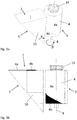
- the Figures 3a and 3b show a perspective view ( figure 3a ) a side view ( figure 3b ) of a portion of the power reserve display device, in which the prism 10 and the roller 3 are visible.
- the pattern 4 comprises a first clear area 4a and a second dark area 4b.
- the reflecting surface 5 of the prism 10 reflects the pattern 4 on the projection surface 7 which corresponds to the upper surface of the prism 10 and which is preferably parallel to the dial of the timepiece.
- the figure 4 shows an example of roller 3 in which the pattern 4 comprises a first clear area 4a and a second dark area 4b, the demarcation between the two areas 4a, 4b forming a straight line making an angle ⁇ with the axis of rotation 8 greater than 0 ° and less than 90 °.
- the image projected onto the projection surface 7 shows a proportion of the first zone (4a) clear more that increases relative to the second dark zone 4b.
- the pattern 4 can be arranged so that, in an initial angular position of the roll 3 which corresponds to the fully raised engine cylinder, the pattern 4 has only the second dark zone 4b with respect to the prism 10 and that the second zone 4b is gradually replaced by the first zone 4a clear as the engine cylinder discharges. In a final angular position of the roller 3 which corresponds to the fully discharged motor barrel, the pattern 4 has only the first zone 4a clear vis-à-vis the prism 10.
- the image projected on the projection surface 7 displays a dark bar (corresponding to the second zone 4b) indicating a maximum power reserve, when the engine cylinder is completely reassembled.
- the dark bar displayed on the projection surface 7 is gradually replaced by a light bar, in proportion with the residual power reserve, and a clear bar is displayed when the engine cylinder is completely discharged.
- the colors chosen for the first and second zones 4a and 4b are preferably such as to establish a good contrast between the two zones 4a and 4b.
- the first zone 4a visually differs from the second zone 4b, preferably, so that the two zones 4a, 4b are easily distinguishable from each other.
- the first area 4a may be of one color (such as red) and the second area 4b of another color (such as black). It is then possible to display on the projection surface 7 an entirely black strip when the watch (of the engine cylinder) is fully charged, the band filling up more and more red as the watch is discharged. .
- the demarcation between the first zone 4a and the second zone 4b is rather helical.
- the dividing line between the first and the second zone 4a, 4b forms any function whose slope of the tangent 15 forms an angle ⁇ with the axis of rotation 8 greater than 0 ° and smaller than 90 ° on at least a portion of the line.
- the image projected on the projection surface 7 displays the first and the second zone 4a, 4b in a proportion that varies continuously according to the angular position of the roller 3, and therefore of the power reserve in the illustrative example.
- the demarcation line separating the first and the second zone 4a, 4b moves on the projection surface 7 according to the angular position of the roll 3.
- the pattern 4 appearing on the periphery of the roll 3 is not limited to two visually distinct zones 4a, 4b, as in the examples above, but may take other forms. allowing the projected image on the projection surface 7 to display any indication.
- the pattern 4 may comprise a plurality of areas, each of the areas having a visual appearance that differs from other areas.
- the zones are arranged around the periphery of the roll 3 so that the visual appearance of the image 4 projected on the projection surface 7 varies according to the angular position of the roll.
- the reflecting surface 5 of the prism 10 makes an angle ⁇ of about 45 ° with the axis of rotation 8 of the roll 3 so as to project the image on the projection surface 7 substantially perpendicular to the axis of rotation 8.
- the angle ⁇ may be non-zero and smaller than 90 ° with the axis of rotation 8.
- the reflecting surface 5 may be formed of a plane mirror at an angle ⁇ with the axis of rotation 8 of the roller 3.
- the reflecting surface 5 may also be the face of a triangular prism.
- the reflecting surface 5 may comprise two reflective surfaces of a pentaprism.
- the image can be projected onto the projection surface 7 substantially perpendicular to the axis of rotation 8 of the roll 3.
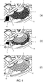
- the Figures 6a to 6c represent the device for the power reserve display included in a watch movement, according to one embodiment.
- the movement is only partially visible.
- the rocket 1 driving the roller 3 through the gear train 6, and the prism 10 and the projection surface 7.
- These elements are, for example, mounted on a plate 16 of the movement.
- the projection surface 7 is arranged substantially parallel to the plane of the plate.
- the movement may comprise a dial (not shown) so that the projection surface 7 is visible on the surface of the dial by example through a window (not shown) practiced in the dial or by transparency.
- figure 6a shows the power reserve display device when the engine cylinder is loaded.
- the chain 2 is completely wound on the rocket 1.
- the roller is in an initial angular position in which the image projected by the pattern 4 on the projection surface 7 displays a completely dark bar indicating a maximum power reserve.
- the figure 6b shows the power reserve display device when the engine cylinder is partially unloaded.
- the chain 2 unrolls the rocket 1 and gradually winds on the barrel by pulling on the rocket 1 with a lever arm continuously increasing so as to compensate for the reduction of the spring force of the barrel engine.
- the roller is in an intermediate angular position in which the image projected by the pattern 4 on the projection surface 7 displays a bar in dark part and partly clear, indicating an intermediate power reserve.
- the Figure 6c shows the power reserve display device when the engine cylinder is fully discharged.
- the chain 2 is completely unrolled from the rocket 1 and the roller is in a final angular position in which the image projected by the pattern 4 on the projection surface 7 displays a bar completely clear, indicating a zero power reserve.
- the device of the invention can be used for displays other than the power reserve poster.
- the roller 3 can be rotated by a display angle given by a kinematic connection so that the visual appearance of the image of the pattern 4 projected on the projection surface 7 varies according to the angular position of the roller 3 to change the indication of the display in the desired manner.
- the roller 3 can be kinematically linked to the engine cylinder other than via a rocket, for example by means of a gear train.
- the angular position of the roller can be controlled by the user, for example in the case of an indicator of the position of the crown rod.
- the roller 3 and the reflecting surface 5 can also be configured so that the projection surface 7 is located at a middle of a watch case comprising the movement or still at the bottom of the case.
Landscapes
- Physics & Mathematics (AREA)
- General Physics & Mathematics (AREA)
- Electromechanical Clocks (AREA)
Claims (14)
- Anzeigevorrichtung für ein Uhrwerk, wobei die Vorrichtung umfasst:
eine Rolle (3), welche angeordnet ist, um durch einen Getriebezug drehend um eine Drehachse (8) angetrieben zu werden, und mit einem Muster (4) an ihrem Umfang; und dadurch gekennzeichnet, dass die Vorrichtung umfasst:mindestens eine reflektierende Oberfläche (5), welche angeordnet ist, um ein Bild des Musters (4) auf eine Projektionsfläche (7) zu projizieren,wobei das Muster (4) auf dem Umfang der Rolle (3) herum variiert, so dass das visuelle Erscheinungsbild des auf die Projektionsfläche (7) projizierten Bildes des Musters (4) in Abhängigkeit von der Winkelposition der Rolle (3) variiert. - Vorrichtung gemäss Anspruch 1, wobei die Rolle (3) durch ein Antriebsfederhaus des Uhrwerks in Drehung angetrieben wird, durch einen Getriebezug, welcher konfiguriert ist, um das Antriebsfederhaus mit der Rolle (3) kinematisch zu koppeln.
- Vorrichtung gemäss Anspruch 2, mit einer Schnecke (1), die dazu bestimmt ist, kinematisch mit dem Antriebsfederhaus gekoppelt zu werden, so dass die Schnecke (1) schwenkbar angetrieben wird, wenn das Antriebsfederhaus aufgewunden und entladen wird, wobei die Rolle (3) von der Schnecke (1) in Drehung angetrieben wird.
- Vorrichtung gemäss Anspruch 3, zudem mit einem Getriebezug (6) zwischen der Schnecke (1) und der Rolle (3), so dass sich die Rolle (3) um einen vorgegebenen Anzeigewinkel zwischen dem vollständig aufgewundenen Zustand und dem vollständig entladenen Zustand des Antriebsfederhauses dreht.
- Vorrichtung gemäss einem der Ansprüche 1 bis 4, worin die Vorrichtung die Gangreserve des Antriebsfederhauses anzeigt.
- Vorrichtung gemäss einem der Ansprüche 1 bis 5, worin das Muster (4) eine Vielzahl von Zonen (4a, 4b) umfasst, wobei jede der Zonen jeweils ein von anderen Zonen verschiedenes visuelles Erscheinungsbild aufweist.
- Vorrichtung gemäss Anspruch 6, worin das Muster (4) eine erste Zone (4a) und eine zweite Zone (4b) mit einem anderen visuellen Erscheinungsbild als das der ersten Zone (4a) aufweist, so dass sich der sichtbare Anteil der ersten Zone (4a) und der zweiten Zone (4b) auf der Oberfläche (7) entsprechend der Winkelposition der Rolle (3) ändert.
- Vorrichtung gemäss Anspruch 7, worin eine Abgrenzungslinie zwischen der ersten und der zweiten Zone (4a, 4b) eine gerade Linie in einem Winkel (θ) mit der Drehachse (8) grösser als 0° und kleiner als 90° bildet.
- Vorrichtung gemäss Anspruch 7, worin eine Abgrenzungslinie zwischen der ersten und der zweiten Zone (4a, 4b) irgendeine Funktion bildet, deren Neigung der Tangente einen Winkel (θ) mit der Drehachse (8) grösser als 0° und kleiner als 90° auf mindestens einem Teil der Linie bildet.
- Vorrichtung gemäss einem der Ansprüche 1 bis 9, worin die besagte mindestens eine reflektierende Oberfläche (5) eine ebene Fläche eines Prismas (10) aufweist.
- Vorrichtung gemäss einem der Ansprüche 1 bis 10, worin die besagte Projektionsfläche (7) im Wesentlichen senkrecht zur Drehachse (8) der Rolle (3) ist.
- Uhr mit der Vorrichtung gemäss einem der Ansprüche 1 bis 11.
- Uhr gemäss Anspruch 12, mit einem Zifferblatt, wobei die besagte mindestens eine reflektierende Oberfläche (5) so konfiguriert ist, dass die Projektionsfläche (7) auf der Oberfläche des Zifferblatts sichtbar ist.
- Uhr gemäss Anspruch 13, worin die Projektionsfläche (7) durch ein Fenster im Zifferblatt erscheint.
Applications Claiming Priority (1)
| Application Number | Priority Date | Filing Date | Title |
|---|---|---|---|
| CH00214/17A CH713484A1 (fr) | 2017-02-24 | 2017-02-24 | Dispositif d'affichage pour un mouvement de montre, notamment d'affichage de réserve de marche. |
Publications (2)
| Publication Number | Publication Date |
|---|---|
| EP3367181A1 EP3367181A1 (de) | 2018-08-29 |
| EP3367181B1 true EP3367181B1 (de) | 2019-10-02 |
Family
ID=58212862
Family Applications (1)
| Application Number | Title | Priority Date | Filing Date |
|---|---|---|---|
| EP18157996.2A Active EP3367181B1 (de) | 2017-02-24 | 2018-02-22 | Anzeigevorrichtung der gangreserve |
Country Status (2)
| Country | Link |
|---|---|
| EP (1) | EP3367181B1 (de) |
| CH (1) | CH713484A1 (de) |
Family Cites Families (7)
| Publication number | Priority date | Publication date | Assignee | Title |
|---|---|---|---|---|
| DE1377059U (de) * | ||||
| CH336760A (fr) * | 1957-02-22 | 1959-02-28 | Schild Sa A | Dispositif indicateur de réserve de marche |
| US3587222A (en) * | 1969-06-20 | 1971-06-28 | Robert Mestrovic | Linear clock |
| CH699021B1 (fr) * | 2006-03-17 | 2010-01-15 | Bnb Concept Sa | Module de base pour pièce d'horlogerie, notamment montre-bracelet. |
| CH705336B1 (fr) * | 2007-09-01 | 2013-02-15 | Christophe Claret Sa | Mécanisme d'affichage des phases de lune. |
| TR201103182A2 (tr) * | 2011-04-01 | 2011-09-21 | Evren Yildirim Cuma | Ayna yansımalı saat kadranı. |
| CH706209B1 (fr) * | 2012-03-07 | 2016-06-30 | Montres Romain Gauthier Sa | Mouvement de montre comprenant un barillet à couple constant. |
-
2017
- 2017-02-24 CH CH00214/17A patent/CH713484A1/fr not_active Application Discontinuation
-
2018
- 2018-02-22 EP EP18157996.2A patent/EP3367181B1/de active Active
Non-Patent Citations (1)
| Title |
|---|
| None * |
Also Published As
| Publication number | Publication date |
|---|---|
| CH713484A1 (fr) | 2018-08-31 |
| EP3367181A1 (de) | 2018-08-29 |
Similar Documents
| Publication | Publication Date | Title |
|---|---|---|
| EP3267267B1 (de) | Anzeigemechanismus der mondphasen | |
| EP3627240B1 (de) | Walzenanzeigemechanismus für armbanduhr | |
| EP2360535A1 (de) | Gangreserve-Anzeigevorrichtung, die in der Schwungmasse eines Uhrwerks mit automatischem Aufzug integriert ist | |
| EP2013667B1 (de) | Bandanzeige-uhr | |
| EP3830649A1 (de) | Elastischer uhrzeiger | |
| WO2014095728A1 (fr) | Piece d'horlogerie a affichage de l'heure universelle | |
| CH699276B1 (fr) | Pièce d'horlogerie comportant un mécanisme de remontage automatique. | |
| EP3570119B1 (de) | Anzeigemechanismus eines sich periodisch wiederholenden ereignisses, und mit einem solchen mechanismus ausgestattete uhr | |
| EP3696617A1 (de) | Monats- und schaltjahr-anzeigemechanismus für uhr | |
| EP3367181A1 (de) | Anzeigevorrichtung der gangreserve | |
| CH700958A2 (fr) | Montre a mouvement mobile. | |
| EP3629101B1 (de) | Uhranzeigemechanismus | |
| EP1612625B1 (de) | Gangreserveanzeige für eine mechanische Uhr | |
| CH705806B1 (fr) | Dispositif d'affichage pour une pièce d'horlogerie. | |
| EP0509403A1 (de) | Uhrwerk | |
| CH702733A2 (fr) | Dispositif indicateur de réserve de marche intégré dans la masse oscillante d'un mouvement à remontage automatique. | |
| CH681190B5 (de) | ||
| CH715842A2 (fr) | Mécanisme d'affichage de mois et d'année bissextile pour pièce d'horlogerie. | |
| WO2024178518A1 (fr) | Dispositif d'affichage de réserve de marche pour pièce d'horlogerie | |
| EP3769159B1 (de) | Zeitmessendes übertragungssystem | |
| EP2088481A2 (de) | Vorrichtung zur Anzeige einer Zeiteinheit | |
| EP1866708B1 (de) | Uhr | |
| CH721836A2 (fr) | Mécanisme indicateur de la réserve de marche agencé pour éviter un désindexage | |
| EP2254007B1 (de) | Anzeigevorrichtung der Gangreserve für Uhr | |
| CH718037A2 (fr) | Mécanisme d'affichage numérique pour chronographe à rattrapante et chronographe comportant un tel mécanisme. |
Legal Events
| Date | Code | Title | Description |
|---|---|---|---|
| PUAI | Public reference made under article 153(3) epc to a published international application that has entered the european phase |
Free format text: ORIGINAL CODE: 0009012 |
|
| STAA | Information on the status of an ep patent application or granted ep patent |
Free format text: STATUS: THE APPLICATION HAS BEEN PUBLISHED |
|
| AK | Designated contracting states |
Kind code of ref document: A1 Designated state(s): AL AT BE BG CH CY CZ DE DK EE ES FI FR GB GR HR HU IE IS IT LI LT LU LV MC MK MT NL NO PL PT RO RS SE SI SK SM TR |
|
| AX | Request for extension of the european patent |
Extension state: BA ME |
|
| STAA | Information on the status of an ep patent application or granted ep patent |
Free format text: STATUS: REQUEST FOR EXAMINATION WAS MADE |
|
| 17P | Request for examination filed |
Effective date: 20190206 |
|
| RBV | Designated contracting states (corrected) |
Designated state(s): AL AT BE BG CH CY CZ DE DK EE ES FI FR GB GR HR HU IE IS IT LI LT LU LV MC MK MT NL NO PL PT RO RS SE SI SK SM TR |
|
| GRAP | Despatch of communication of intention to grant a patent |
Free format text: ORIGINAL CODE: EPIDOSNIGR1 |
|
| STAA | Information on the status of an ep patent application or granted ep patent |
Free format text: STATUS: GRANT OF PATENT IS INTENDED |
|
| RIC1 | Information provided on ipc code assigned before grant |
Ipc: G04B 19/21 20060101ALI20190328BHEP Ipc: G04B 9/00 20060101AFI20190328BHEP |
|
| INTG | Intention to grant announced |
Effective date: 20190424 |
|
| RIN1 | Information on inventor provided before grant (corrected) |
Inventor name: HOURIET, ARNAUD Inventor name: RANERI, GIONATAN Inventor name: CASSE, ARNAUD Inventor name: DREYER-GONZALES, FREDERIC |
|
| GRAS | Grant fee paid |
Free format text: ORIGINAL CODE: EPIDOSNIGR3 |
|
| GRAA | (expected) grant |
Free format text: ORIGINAL CODE: 0009210 |
|
| STAA | Information on the status of an ep patent application or granted ep patent |
Free format text: STATUS: THE PATENT HAS BEEN GRANTED |
|
| AK | Designated contracting states |
Kind code of ref document: B1 Designated state(s): AL AT BE BG CH CY CZ DE DK EE ES FI FR GB GR HR HU IE IS IT LI LT LU LV MC MK MT NL NO PL PT RO RS SE SI SK SM TR |
|
| REG | Reference to a national code |
Ref country code: GB Ref legal event code: FG4D Free format text: NOT ENGLISH |
|
| REG | Reference to a national code |
Ref country code: CH Ref legal event code: EP Ref country code: CH Ref legal event code: NV Representative=s name: P&TS SA, CH Ref country code: AT Ref legal event code: REF Ref document number: 1186877 Country of ref document: AT Kind code of ref document: T Effective date: 20191015 |
|
| REG | Reference to a national code |
Ref country code: DE Ref legal event code: R096 Ref document number: 602018000748 Country of ref document: DE |
|
| REG | Reference to a national code |
Ref country code: IE Ref legal event code: FG4D Free format text: LANGUAGE OF EP DOCUMENT: FRENCH |
|
| REG | Reference to a national code |
Ref country code: NL Ref legal event code: MP Effective date: 20191002 |
|
| REG | Reference to a national code |
Ref country code: LT Ref legal event code: MG4D |
|
| REG | Reference to a national code |
Ref country code: AT Ref legal event code: MK05 Ref document number: 1186877 Country of ref document: AT Kind code of ref document: T Effective date: 20191002 |
|
| PG25 | Lapsed in a contracting state [announced via postgrant information from national office to epo] |
Ref country code: LT Free format text: LAPSE BECAUSE OF FAILURE TO SUBMIT A TRANSLATION OF THE DESCRIPTION OR TO PAY THE FEE WITHIN THE PRESCRIBED TIME-LIMIT Effective date: 20191002 Ref country code: PL Free format text: LAPSE BECAUSE OF FAILURE TO SUBMIT A TRANSLATION OF THE DESCRIPTION OR TO PAY THE FEE WITHIN THE PRESCRIBED TIME-LIMIT Effective date: 20191002 Ref country code: GR Free format text: LAPSE BECAUSE OF FAILURE TO SUBMIT A TRANSLATION OF THE DESCRIPTION OR TO PAY THE FEE WITHIN THE PRESCRIBED TIME-LIMIT Effective date: 20200103 Ref country code: NO Free format text: LAPSE BECAUSE OF FAILURE TO SUBMIT A TRANSLATION OF THE DESCRIPTION OR TO PAY THE FEE WITHIN THE PRESCRIBED TIME-LIMIT Effective date: 20200102 Ref country code: AT Free format text: LAPSE BECAUSE OF FAILURE TO SUBMIT A TRANSLATION OF THE DESCRIPTION OR TO PAY THE FEE WITHIN THE PRESCRIBED TIME-LIMIT Effective date: 20191002 Ref country code: SE Free format text: LAPSE BECAUSE OF FAILURE TO SUBMIT A TRANSLATION OF THE DESCRIPTION OR TO PAY THE FEE WITHIN THE PRESCRIBED TIME-LIMIT Effective date: 20191002 Ref country code: LV Free format text: LAPSE BECAUSE OF FAILURE TO SUBMIT A TRANSLATION OF THE DESCRIPTION OR TO PAY THE FEE WITHIN THE PRESCRIBED TIME-LIMIT Effective date: 20191002 Ref country code: BG Free format text: LAPSE BECAUSE OF FAILURE TO SUBMIT A TRANSLATION OF THE DESCRIPTION OR TO PAY THE FEE WITHIN THE PRESCRIBED TIME-LIMIT Effective date: 20200102 Ref country code: PT Free format text: LAPSE BECAUSE OF FAILURE TO SUBMIT A TRANSLATION OF THE DESCRIPTION OR TO PAY THE FEE WITHIN THE PRESCRIBED TIME-LIMIT Effective date: 20200203 Ref country code: FI Free format text: LAPSE BECAUSE OF FAILURE TO SUBMIT A TRANSLATION OF THE DESCRIPTION OR TO PAY THE FEE WITHIN THE PRESCRIBED TIME-LIMIT Effective date: 20191002 Ref country code: ES Free format text: LAPSE BECAUSE OF FAILURE TO SUBMIT A TRANSLATION OF THE DESCRIPTION OR TO PAY THE FEE WITHIN THE PRESCRIBED TIME-LIMIT Effective date: 20191002 Ref country code: NL Free format text: LAPSE BECAUSE OF FAILURE TO SUBMIT A TRANSLATION OF THE DESCRIPTION OR TO PAY THE FEE WITHIN THE PRESCRIBED TIME-LIMIT Effective date: 20191002 |
|
| PG25 | Lapsed in a contracting state [announced via postgrant information from national office to epo] |
Ref country code: IS Free format text: LAPSE BECAUSE OF FAILURE TO SUBMIT A TRANSLATION OF THE DESCRIPTION OR TO PAY THE FEE WITHIN THE PRESCRIBED TIME-LIMIT Effective date: 20200224 Ref country code: CZ Free format text: LAPSE BECAUSE OF FAILURE TO SUBMIT A TRANSLATION OF THE DESCRIPTION OR TO PAY THE FEE WITHIN THE PRESCRIBED TIME-LIMIT Effective date: 20191002 Ref country code: HR Free format text: LAPSE BECAUSE OF FAILURE TO SUBMIT A TRANSLATION OF THE DESCRIPTION OR TO PAY THE FEE WITHIN THE PRESCRIBED TIME-LIMIT Effective date: 20191002 Ref country code: RS Free format text: LAPSE BECAUSE OF FAILURE TO SUBMIT A TRANSLATION OF THE DESCRIPTION OR TO PAY THE FEE WITHIN THE PRESCRIBED TIME-LIMIT Effective date: 20191002 |
|
| PG25 | Lapsed in a contracting state [announced via postgrant information from national office to epo] |
Ref country code: AL Free format text: LAPSE BECAUSE OF FAILURE TO SUBMIT A TRANSLATION OF THE DESCRIPTION OR TO PAY THE FEE WITHIN THE PRESCRIBED TIME-LIMIT Effective date: 20191002 |
|
| REG | Reference to a national code |
Ref country code: DE Ref legal event code: R097 Ref document number: 602018000748 Country of ref document: DE |
|
| PG2D | Information on lapse in contracting state deleted |
Ref country code: IS |
|
| PG25 | Lapsed in a contracting state [announced via postgrant information from national office to epo] |
Ref country code: RO Free format text: LAPSE BECAUSE OF FAILURE TO SUBMIT A TRANSLATION OF THE DESCRIPTION OR TO PAY THE FEE WITHIN THE PRESCRIBED TIME-LIMIT Effective date: 20191002 Ref country code: EE Free format text: LAPSE BECAUSE OF FAILURE TO SUBMIT A TRANSLATION OF THE DESCRIPTION OR TO PAY THE FEE WITHIN THE PRESCRIBED TIME-LIMIT Effective date: 20191002 Ref country code: DK Free format text: LAPSE BECAUSE OF FAILURE TO SUBMIT A TRANSLATION OF THE DESCRIPTION OR TO PAY THE FEE WITHIN THE PRESCRIBED TIME-LIMIT Effective date: 20191002 Ref country code: IS Free format text: LAPSE BECAUSE OF FAILURE TO SUBMIT A TRANSLATION OF THE DESCRIPTION OR TO PAY THE FEE WITHIN THE PRESCRIBED TIME-LIMIT Effective date: 20200202 |
|
| PLBE | No opposition filed within time limit |
Free format text: ORIGINAL CODE: 0009261 |
|
| STAA | Information on the status of an ep patent application or granted ep patent |
Free format text: STATUS: NO OPPOSITION FILED WITHIN TIME LIMIT |
|
| PG25 | Lapsed in a contracting state [announced via postgrant information from national office to epo] |
Ref country code: SM Free format text: LAPSE BECAUSE OF FAILURE TO SUBMIT A TRANSLATION OF THE DESCRIPTION OR TO PAY THE FEE WITHIN THE PRESCRIBED TIME-LIMIT Effective date: 20191002 Ref country code: SK Free format text: LAPSE BECAUSE OF FAILURE TO SUBMIT A TRANSLATION OF THE DESCRIPTION OR TO PAY THE FEE WITHIN THE PRESCRIBED TIME-LIMIT Effective date: 20191002 |
|
| 26N | No opposition filed |
Effective date: 20200703 |
|
| REG | Reference to a national code |
Ref country code: BE Ref legal event code: MM Effective date: 20200229 |
|
| PG25 | Lapsed in a contracting state [announced via postgrant information from national office to epo] |
Ref country code: LU Free format text: LAPSE BECAUSE OF NON-PAYMENT OF DUE FEES Effective date: 20200222 Ref country code: MC Free format text: LAPSE BECAUSE OF FAILURE TO SUBMIT A TRANSLATION OF THE DESCRIPTION OR TO PAY THE FEE WITHIN THE PRESCRIBED TIME-LIMIT Effective date: 20191002 |
|
| PG25 | Lapsed in a contracting state [announced via postgrant information from national office to epo] |
Ref country code: SI Free format text: LAPSE BECAUSE OF FAILURE TO SUBMIT A TRANSLATION OF THE DESCRIPTION OR TO PAY THE FEE WITHIN THE PRESCRIBED TIME-LIMIT Effective date: 20191002 |
|
| PG25 | Lapsed in a contracting state [announced via postgrant information from national office to epo] |
Ref country code: IE Free format text: LAPSE BECAUSE OF NON-PAYMENT OF DUE FEES Effective date: 20200222 |
|
| PG25 | Lapsed in a contracting state [announced via postgrant information from national office to epo] |
Ref country code: BE Free format text: LAPSE BECAUSE OF NON-PAYMENT OF DUE FEES Effective date: 20200229 |
|
| PG25 | Lapsed in a contracting state [announced via postgrant information from national office to epo] |
Ref country code: TR Free format text: LAPSE BECAUSE OF FAILURE TO SUBMIT A TRANSLATION OF THE DESCRIPTION OR TO PAY THE FEE WITHIN THE PRESCRIBED TIME-LIMIT Effective date: 20191002 Ref country code: MT Free format text: LAPSE BECAUSE OF FAILURE TO SUBMIT A TRANSLATION OF THE DESCRIPTION OR TO PAY THE FEE WITHIN THE PRESCRIBED TIME-LIMIT Effective date: 20191002 Ref country code: CY Free format text: LAPSE BECAUSE OF FAILURE TO SUBMIT A TRANSLATION OF THE DESCRIPTION OR TO PAY THE FEE WITHIN THE PRESCRIBED TIME-LIMIT Effective date: 20191002 |
|
| PG25 | Lapsed in a contracting state [announced via postgrant information from national office to epo] |
Ref country code: MK Free format text: LAPSE BECAUSE OF FAILURE TO SUBMIT A TRANSLATION OF THE DESCRIPTION OR TO PAY THE FEE WITHIN THE PRESCRIBED TIME-LIMIT Effective date: 20191002 |
|
| REG | Reference to a national code |
Ref country code: DE Ref legal event code: R081 Ref document number: 602018000748 Country of ref document: DE Owner name: RICHEMONT INTERNATIONAL SA, CH Free format text: FORMER OWNER: OFFICINE PANERAI AG, STEINHAUSEN, CH |
|
| REG | Reference to a national code |
Ref country code: GB Ref legal event code: 732E Free format text: REGISTERED BETWEEN 20241114 AND 20241120 |
|
| REG | Reference to a national code |
Ref country code: CH Ref legal event code: U11 Free format text: ST27 STATUS EVENT CODE: U-0-0-U10-U11 (AS PROVIDED BY THE NATIONAL OFFICE) Effective date: 20260301 |
|
| PGFP | Annual fee paid to national office [announced via postgrant information from national office to epo] |
Ref country code: GB Payment date: 20260219 Year of fee payment: 9 |
|
| PGFP | Annual fee paid to national office [announced via postgrant information from national office to epo] |
Ref country code: DE Payment date: 20260218 Year of fee payment: 9 |
|
| PGFP | Annual fee paid to national office [announced via postgrant information from national office to epo] |
Ref country code: IT Payment date: 20260224 Year of fee payment: 9 |
|
| PGFP | Annual fee paid to national office [announced via postgrant information from national office to epo] |
Ref country code: FR Payment date: 20260218 Year of fee payment: 9 |
|
| PGFP | Annual fee paid to national office [announced via postgrant information from national office to epo] |
Ref country code: CH Payment date: 20260301 Year of fee payment: 9 |