EP3368730B1 - Équipement grimpant pour la construction de bâtiments - Google Patents
Équipement grimpant pour la construction de bâtiments Download PDFInfo
- Publication number
- EP3368730B1 EP3368730B1 EP16801580.8A EP16801580A EP3368730B1 EP 3368730 B1 EP3368730 B1 EP 3368730B1 EP 16801580 A EP16801580 A EP 16801580A EP 3368730 B1 EP3368730 B1 EP 3368730B1
- Authority
- EP
- European Patent Office
- Prior art keywords
- scaffold
- coupling
- traction device
- under construction
- building
- Prior art date
- Legal status (The legal status is an assumption and is not a legal conclusion. Google has not performed a legal analysis and makes no representation as to the accuracy of the status listed.)
- Active
Links
Images









Classifications
-
- E—FIXED CONSTRUCTIONS
- E04—BUILDING
- E04G—SCAFFOLDING; FORMS; SHUTTERING; BUILDING IMPLEMENTS OR AIDS, OR THEIR USE; HANDLING BUILDING MATERIALS ON THE SITE; REPAIRING, BREAKING-UP OR OTHER WORK ON EXISTING BUILDINGS
- E04G3/00—Scaffolds essentially supported by building constructions, e.g. adjustable in height
- E04G3/28—Mobile scaffolds; Scaffolds with mobile platforms
-
- E—FIXED CONSTRUCTIONS
- E04—BUILDING
- E04G—SCAFFOLDING; FORMS; SHUTTERING; BUILDING IMPLEMENTS OR AIDS, OR THEIR USE; HANDLING BUILDING MATERIALS ON THE SITE; REPAIRING, BREAKING-UP OR OTHER WORK ON EXISTING BUILDINGS
- E04G11/00—Forms, shutterings, or falsework for making walls, floors, ceilings, or roofs
- E04G11/06—Forms, shutterings, or falsework for making walls, floors, ceilings, or roofs for walls, e.g. curved end panels for wall shutterings; filler elements for wall shutterings; shutterings for vertical ducts
- E04G11/20—Movable forms; Movable forms for moulding cylindrical, conical or hyperbolical structures; Templates serving as forms for positioning blocks or the like
- E04G11/28—Climbing forms, i.e. forms which are not in contact with the poured concrete during lifting from layer to layer and which are anchored in the hardened concrete
-
- E—FIXED CONSTRUCTIONS
- E04—BUILDING
- E04G—SCAFFOLDING; FORMS; SHUTTERING; BUILDING IMPLEMENTS OR AIDS, OR THEIR USE; HANDLING BUILDING MATERIALS ON THE SITE; REPAIRING, BREAKING-UP OR OTHER WORK ON EXISTING BUILDINGS
- E04G3/00—Scaffolds essentially supported by building constructions, e.g. adjustable in height
- E04G3/20—Scaffolds essentially supported by building constructions, e.g. adjustable in height supported by walls
-
- E—FIXED CONSTRUCTIONS
- E04—BUILDING
- E04G—SCAFFOLDING; FORMS; SHUTTERING; BUILDING IMPLEMENTS OR AIDS, OR THEIR USE; HANDLING BUILDING MATERIALS ON THE SITE; REPAIRING, BREAKING-UP OR OTHER WORK ON EXISTING BUILDINGS
- E04G3/00—Scaffolds essentially supported by building constructions, e.g. adjustable in height
- E04G3/28—Mobile scaffolds; Scaffolds with mobile platforms
- E04G2003/286—Mobile scaffolds; Scaffolds with mobile platforms mobile vertically
Definitions
- the present invention relates to climbing equipment for the construction of buildings, even for buildings of particular height extension, such as skyscrapers or high-rise blocks.
- the present invention relates to self-climbing equipment for the construction of a building.
- the present invention relates to climbing equipment for the construction of buildings preferably having a steel supporting structure.
- Equipment for the construction of buildings even of considerable height, e.g. skyscrapers or high-rise blocks, are known, comprising at least one scaffold which by resting on the ground or on the building base extends over the entire height of the building under construction.
- Scaffold solutions anchored to portions of the building under construction are also known. Solutions of this type are invasive and require long times to construct a height increase of the scaffold as the building under construction increases in height.
- document JP-H-0776934-A shows a steel skeleton adapted to hang from the structure of a skyscraper under construction, comprising a winch, adapted to cooperate with a crane for lifting building materials and deliver them to the level of the floor to be built.
- This solution requires to hang said steel skeleton at a much higher level than the level of the floor to be built.
- Equipment is also known for the construction of buildings, comprising a scaffold and a scaffold ascent system, adapted to climb up the building under construction.
- Korean patent No. KR-100862275-B1 shows a scaffold for the construction of skyscrapers comprising a scaffold ascent system with respect to the building under construction comprising a screw actuator.
- European patent No. EP-2365159-B1 shows ascending equipment for the construction of buildings comprising a scaffold adapted to climb up the building under construction.
- Said scaffold comprises at least one pair of anchors which are screwed to at least two floors of the building arranged at different heights, so as to allow the sliding of the scaffold with respect to guide rings connected to said anchors.
- a jack moves the scaffold upwards.
- a platform projects like a cantilever from said movable scaffold outwards, i.e. in an opposite direction with respect to the extension of said at least one pair of anchors.
- the solution described above requires to spend time to screw the anchors to the upper floors of the building under construction.
- including a platform which projects like a cantilever from the movable scaffold towards the opposite side with respect to the side of said anchors to the building under construction offers neither satisfactory safety for operators nor sufficient protection from the danger of falling objects or construction materials.
- document US-2015-101887-A1 shows a lifting device of a movable scaffold which comprises a jack which is anchored to the building under construction and pushes the scaffold upwards.
- a solution of this type requires to anchor and free the jack to and from the building under construction to allow the scaffold to ascend as new floors of the building under construction are constructed.
- Further examples of equipment for the construction of buildings are known from documents KR-2013-0077176-A and JP-2002-194893-A .
- document NL-8004572-A which discloses the features of the preamble of claim 1, shows a telescopically extensible scaffolding system for curved walled towers made of reinforced concrete, in which brackets are embedded in the concrete of the tower to serve as support for said scaffolding system.
- This solution requires a laborious preparation and a slow telescopic extension process of the scaffolding system which must be fixed by means of pins to the brackets embedded in the concrete of the tower.
- the aforesaid solutions do not provide adequate protection for operators and at the same time fail in preventing the falling of equipment and debris from the scaffolding in a satisfactory manner.
- the mentioned solutions require long moving times of the scaffolding in vertical or subvertical direction and thus impose long waits before making even only part of the building usable.
- climbing equipment for the construction of a building, or of a building under construction comprising a plurality of building floors, comprises at least one scaffold, adapted to surround at least partially the perimeter of at least one building floor, wherein said scaffold comprises at least one work platform, adapted to form a walkable surface and adapted to project like a cantilever from said scaffold towards said building under construction, wherein at least some of said at least one work platforms being adapted to close the open space between said scaffold and said building under construction.
- climbing equipment further comprises a traction device comprising at least a first portion, or first portion, integral with said scaffold, and at least a second portion, or second portion, connected to said first portion, wherein said at least a first portion comprises at least a first coupling element and said at least a second portion comprises at least a second coupling element, and wherein said first coupling element is adapted to grip a first coupling portion of said building under construction and wherein said second coupling element is adapted to grip a second coupling portion of said building under construction, and wherein said first coupling portion is arranged at a different level than said second coupling portion, and wherein said climbing equipment further comprises a moving system, adapted to perform a relative movement between said first portion and said second portion of said traction device, and wherein when at least a first coupling element is released from the respective coupling portion of said building under construction, said moving system is adapted to perform a relative movement between said first portion and said second portion of said traction device, so as to move said scaffold by a pre
- the extension of said scaffold parallel to the direction of relative movement X is greater than said first portion by a predetermined amount.
- said predetermined amount is greater than the height of a building floor.
- climbing equipment for the construction of buildings comprising a scaffold which at least partially, or even entirely, surrounds the side perimeter of a building under construction, avoiding to have a supporting structure which is arranged by the side of the building also extending beyond the floor temporarily under construction so as to ensure the safety of workers even during the construction of new floors.
- a scaffold which at least partially, or even entirely, surrounds the side perimeter of a building under construction, avoiding to have a supporting structure which is arranged by the side of the building also extending beyond the floor temporarily under construction so as to ensure the safety of workers even during the construction of new floors.
- such climbing equipment for the construction of buildings is adapted to provide the building to be constructed rapidly and discreetly, and this allows to use the floors already built of the building under construction.
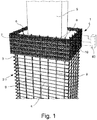
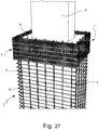
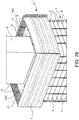
- climbing equipment 1 for the construction of a building 2, or building under construction 2 comprises at least one scaffold 7, or scaffolding 7.
- said climbing equipment 1 is self-climbing equipment for the construction of a building 2.
- said building under construction 2 is a building having a particular height extension, such as a skyscraper or a high-rise block, for example.
- said building under construction 2 comprises a metal frame structure, e.g. made of steel, iron or the like. More preferably, said frame structure of said building under construction 2 comprises a plurality of metal uprights, e.g. made of steel, iron or the like.
- Said building 2, or building under construction 2 comprises a plurality of floors 3.
- "height of a floor 90" means the measurement of the substantially vertical distance between the flooring of a floor and the ceiling of the consecutive, upper floor of said building.
- the height of a building floor 90 may be comprised between about 2 meters and about 4 meters, and preferably comprised between about 2.5 meters and 3.5 meters. Therefore, the height of two building floors is substantially equal to double the height of one floor 90 of said building 2.
- Said scaffold 7 comprises at least one work platform 8, adapted to form a walkable surface and adapted to project like a cantilever from said scaffold 7 towards said building under construction 2, in which at least some of said at least one work platform 8 being adapted to close the open space between said scaffold 7 and said building under construction 2.
- said work platform is overturnable.
- said work platform 8 is overturnable and can pass from at least one extended position, in which it forms a walkable surface which projects like a cantilever from said scaffold 7 towards said building under construction 2, to at least one retracted position, in which it is substantially contained within the clearance of said scaffold 7.
- Including said at least one work platform 8 confers a high degree of safety for operators and a high degree of protection against the accidental falling of objects, debris or other building materials. Furthermore, including such an extensible work platform 8, when in folded position, prevents interfering with the ascending movement of the climbing equipment 1.
- said scaffold 7 comprises at least one scaffolding which defines a walkable surface within the clearance of said scaffolding 7.
- said work platform 8 when it is in extended position, creates a continuous walkable surface with said scaffolding.
- continuous walkable surface does not mean that there is a seamless surface between scaffolding and work platform 8, but that said scaffolding and said work platform 8 form a walkable portion so that an operator can easily and safely move from the work platform 8 to the scaffolding, and vice versa.
- a theoretical peripheral facade surface is defined, comprising one or more theoretical facade surfaces oriented substantially in either vertical or subvertical direction and coinciding with the extension of the previously constructed facades of the building under construction.
- said scaffold 7 comprises at least one protective barrier 36 which extends along the outer edge of said scaffold 7.
- said scaffold 7 comprises a protective cage which extends along the outer edge of said scaffold 7.
- Said climbing equipment 1 further comprises a traction device 10 comprising at least a first portion 11, or first ascending portion 11, integral with said scaffold 7, and at least a second portion 12, or second ascending portion 12, connected to said first portion 11.
- said at least a second portion 12 is slidingly connected to said first portion 11.
- said scaffold 7 is associated with said first portion 11 and said first portion 11 is fitted in a sliding manner on said second portion 12 of said traction device 10.
- said first portion 11 associated with said scaffold 7 embraces said second portion 12 of said traction device 10.
- said first portion 11 of the traction device 10 comprises mutually shaped sliding guides with respect to sliding runners provided on said second portion 12 of the traction device 10.
- said second portion 12 of the traction device 10 comprises mutually shaped sliding guides with respect to sliding runners provided on said first portion 11 of the traction device 10.
- said scaffold 7 is associated with said first portion 11 so as to project like a cantilever forming at least one attachment portion to said first portion 11 of said traction device 10 and at least one suspended cantilevered portion. Said suspended cantilevered portion of said scaffold 7 extends from said first portion 11 in opposite direction with respect to said building under construction 2.
- the extension of said scaffold 7 parallel to the direction of relative movement X is greater than said first portion 11 by a predetermined amount 14.
- said scaffold 7 comprises an excess portion 17, which extends surrounding at least one portion of said theoretical peripheral facade surface.
- said predetermined amount 14 is substantially equal to the height of a building floor 90.
- said predetermined amount 14 is greater than the height of a building floor 90.
- said predetermined amount is substantially equal to the height of two building floors. In other words, said predetermined amount is substantially equal to twice the height of a building floor 90.
- the height extension of said scaffold 7 is greater than said second portion 12 of the traction device 10.
- said second portion 12 of the traction device 10 extends higher up than said first portion 11 of the traction device 10 both during the building ascending climbing movement and when the traction device 10 is stopped.
- said at least a second portion 12 is freely movable with respect to said first portion 11 while being constrained to it at least in one portion thereof.
- said traction device 10 comprises at least one low-friction material layer 13 interposed between said first portion 11 of the traction device 10 and said second portion 12 of the traction device 10 to promote the sliding between said first portion 11 and said second portion 12 of the traction device 10.
- said low-friction material layer is made of Polizene.
- Said at least a first portion 11 comprises at least a first coupling element 21.
- Said at least a second portion 12 comprises at least a second coupling element 22.
- Said first coupling element 21 is adapted to grip a first coupling portion 31 of said building under construction 2.
- Said second coupling element 22 is adapted to grip a second coupling portion 32 of said building under construction 2.
- said frame structure of said building under construction 2 comprises both said at least a first coupling portion 31 and said at least a second coupling portion 32.
- said uprights of the frame structure comprise both said first coupling portion 31 and said second coupling portion 32.
- said uprights of the frame structure comprise a plurality of first coupling portions 31 and a plurality of second coupling portions 32.
- the section of each of said uprights decreases upwards.
- more than one of either said first coupling portion 31 and more than one of said at least a second coupling portion 32 are provided for each floor of building under construction.
- the pitch of the climbing equipment 1 is so determined.
- the traction device 10 performs two extension cycles to ascend each floor, during the climbing movement.
- said climbing equipment 1 comprises further coupling elements 20, adapted to grip further coupling portions 30 of said building under construction 2.
- each of said first coupling element 21 and said second coupling element 22 may also be indicated by reference numeral 20, where said first coupling element 21 and said second coupling element 22 are functionally indistinguishable.
- reference numeral 20 may generally indicate a coupling element.
- each said first coupling portion 31 and said second coupling portion 32 could also be indicated by reference numeral 30, where said first coupling element 31 and said second coupling element 32 are functionally indistinguishable.
- reference numeral 30 may generally indicate a coupling portion.
- said first coupling portion 31 is arranged at a different level than said second coupling portion 32.
- said first coupling portion 31 is connected at a lower level than said second coupling portion 32.
- said second coupling portion 32 is arranged higher than said first coupling portion 31.
- a same coupling portion 30 may work either as a first coupling portion 31 or as second coupling portion 32, preferably at different times.
- said first coupling portion 31 is connected at a higher level than said second coupling portion 32.
- Said climbing equipment 1 further comprises a moving system 15, adapted to perform a relative movement between said first portion 11 and said second portion 12 of said traction device 10.
- said moving system 15 when at least either said first coupling element 21 or said second coupling element 22 is released from the respective coupling portion 31, 32, said moving system 15 is adapted to perform a relative movement between said first portion 11 and said second portion 12 of said traction device 10, so as to move said scaffold 7 by a predetermined movement.
- said moving system 15 moves said first portion 11 with respect to said second portion 12 so as to move said scaffold 7 by a predetermined movement.
- said predetermined movement of said scaffold 7 is a lifting movement. In other words, the movement is directed prevalently upwards. In other words, said predetermined movement of said scaffold 7 is a raising movement.
- said scaffold 7 is associated with said first portion 11 of the traction device 10 like a backpack that the first portion 11 carries therewith during the relative movement of said first portion 11 of the traction device 10 with respect to said second portion 12 of the traction device 10. Thereby, a clear raising movement of said scaffold 7 can be created during the construction of a building.
- said second coupling portion 32 is arranged higher than said first coupling portion 31, and when said at least first coupling element 21 is released from said first coupling portion 31 and said second coupling element 22 is anchored to said second coupling portion 32, said moving system 15 moves from said first portion 11 with respect to said second portion 12, so as to lift said scaffold 7, connected to said first portion 11.
- said predetermined movement involves said scaffold 7 as a whole. In other words, all parts of said scaffold 7 are moved simultaneously with said predetermined movement.
- said climbing equipment 1 comprises a plurality of traction devices 10.
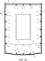
- said climbing equipment 1 comprises sixteen traction devices 10 distributed along the peripheral extension of the scaffold 7.
- said predetermined movement of said scaffold 7 is a lowering movement.
- the movement is directed prevalently downwards.
- said moving system 15 comprises at least one hydraulic actuator.
- it may comprise at least one cylinder-piston assembly.
- said moving system 15 comprises at least one mechanical actuator.
- said moving system 15 comprises at least one electrical-mechanical actuator.
- said moving system 15 comprises at least one jack 16.
- said at least a second portion 12 is telescopically connected to said first portion 11 of said traction device 10.
- said traction device 10 comprises a telescopic system, adapted to pass from said contracted configuration to said extended configuration, and vice versa, by means of the relative sliding between said first portion 11 and said second portion 12.
- Including said telescopic system allows said traction device 10 to extend and contract while ensuring that said first portion 11 and said second portion remain mutually aligned or in axis.
- said second portion 12 is adapted to form the telescopically extensible portion of said traction device 10.
- said second portion 12 is free from the connection with said scaffold 7.
- said second portion 12 slides along at least one guiding channel defined by a reciprocally shaped portion of said first portion 11 of said traction device 10.
- said second portion 12 slides along at least one guiding channel defined by a reciprocally shaped portion of said first portion 11 of said traction device 10.
- said first coupling element 21 is rotationally connected to said first portion 11 of said traction device 10.
- said rotational constraint comprises a fixing pin 26.
- said second coupling element 21 is adapted to project like a cantilever from said first portion 11 of said traction device 10, as a shelf.
- said second coupling element 22 is rotationally connected to said second portion 12 of said traction device 10.
- said rotational constraint comprises a fixing pin 26.
- said second coupling element 22 is adapted to project like a cantilever from said first portion 12 of said traction device 10, like a shelf.
- said first coupling element 20, 21 and second coupling element 20, 22 are overturnable within a position projecting like a cantilever from said traction device 10 and a folded or non-projecting position, so as not to interfere with the ascent of the building under construction 1.
- said first coupling element 21 is connected to a first actuator 41 for moving it between a coupling position, in which it is anchored to said first coupling portion 31, and a releasing position, in which it is not in contact with said first coupling portion 31.
- said first actuator 41 is a hydraulic or pneumatic actuator.
- said first actuator 41 comprises a cylinder-piston assembly.
- said first actuator 41 is extensible within a retracted configuration and an extended configuration.
- said first actuator 41 determines that said first coupling element 21 is in position projecting like a cantilever from said first portion so as to couple to a coupling portion 30, 31 of the building under construction 2.
- said first actuator 41 when said first actuator 41 is in extended configuration, it determines that said first coupling element 21 is in folded or non-projecting position so as to allow the ascent of the building under construction 1 by moving the traction device 10.
- said second actuator 42 is a hydraulic or pneumatic actuator.
- said second actuator 42 comprises a cylinder-piston assembly.
- said second actuator 42 is extensible within a retracted configuration and an extended configuration.
- said second actuator determines that said second coupling element 22 is in position projecting like a cantilever from said second portion so as to couple to a coupling portion 30, 32 of the building under construction 2.
- said second actuator 42 when said second actuator 42 is in extended position, it determines that said second coupling element 22 and is in folded or non-projecting position so as to not interfere with the ascent of the building under construction 1.
- said first actuator 41 extends upwards from said first coupling element 21 to reach said first portion 11 of the traction device 10.
- said second actuator 42 extends upwards from said second coupling element 22 to reach said first portion 12 of the traction device 10.
- At least either said first actuator 41 or said second module 42 comprises at least one hydraulic actuator.
- said hydraulic actuator is a cylinder-piston assembly.
- said equipment 1 comprises a pair of second coupling elements 22, arranged at a different level from each other. This improves the anchoring performance.
- said equipment 1 comprises a pair of second coupling elements 22, arranged substantially at the same level. This improves the anchoring performance.
- at least either said first coupling element 21 or said second coupling element 22 comprises a hook 23.
- each said first coupling element 21 and said second coupling element 22 comprise a hook 23.
- said first coupling portion 31 is arranged higher than said second coupling portion 32.
- At least either said first coupling portion 31 or said second coupling portion 32 comprises a coupling pin 33, or coupling peg 33, adapted to be accommodated in a hole made in a supporting pillar 9, or pillar 9, or upright 9, of the building under construction 2.
- the provision of a coupling peg 33 makes its positioning in said supporting pillar 9 quick and accurate.
- a fixing peg 33 may be inserted into holes provided in said supporting pillar 9. This avoids spending time to anchor or couple said traction device 10 to said building under construction 2.
- the provision of a fixing peg makes the operation quick and easy.
- said coupling pin comprises two opposite ends which project like a cantilever from a profiled supporting pillar 9, said two opposite ends are adapted to form a coupling site for a pair of first coupling elements 21 of said first portion 11 of said traction device 10, and a central portion, interposed between said two ends and doubly constrained to said supporting pillar 9, to form a coupling site for at least a second coupling element 12 of said second portion 12 of said traction device 10.
- the cross section of said coupling pin 33 is greater in said ends which project like a cantilever from said doubly constrained central portion so as to prevent flexural deformations of the cantilevered ends to ensure a firm coupling of said first portion 11 of the traction device 10.
- said coupling element 20, 21 or 22 comprises a seat portion 25, adapted to accommodate said coupling peg 33 at least partially.
- said seat portion 25 is shaped so as to form a plurality of peg seats 27, each adapted to accommodate said coupling peg 33 at least partially.
- said plurality of peg seats 27 are adapted to allow a coupling while minimizing the presence of mechanical clearance even when the distance between the coupling elements 20, 21, 22 and the respective coupling portions 30, 31, 32 is different from that envisaged during the step of designing.
- said second portion 12 of said traction device 10 comprise an extensible resting foot 28, adapted to rest on a portion of said building under construction 2 to keep said climbing equipment 1 substantially parallel to the outer face of the building under construction 2, during the movement of said traction device 10.
- said supporting pillar 9 is a profiled beam.
- said coupling peg 33 is fixed in two disjointed portions thereof to at least one supporting pillar 9 of said building under construction, like a double jointed beam.
- at least either said first coupling element 21 or said second coupling element 22 comprises a bushing 24, adapted to surround at least one portion of said coupling peg 33 so as to locally increase the outer diameter thereof.
- said coupling peg 33 comprises a coupling face 35, adapted to mate with said seat portion 25 of its associated coupling element 20, 21 or 22.
- said coupling face 35 is a smooth surface. According to an embodiment, said coupling face 35 is at least partially knurled. According to an embodiment, said coupling face 35 is at least partially threaded. According to an embodiment, said tapped bushing is adapted to be coupled to said coupling peg when said coupling peg comprises said threaded coupling face. According to an embodiment, said coupling peg 33 comprises at least one portion having a decreased section portion to form a coupling groove. This provides the coupling between coupling pin 33 and coupling element 20.
- the height extension of said scaffold 7 is at least equal to one building floor 3.
- the height extension of said scaffold 7 is equal to a plurality of building floors 3 and less than the height extension of said building under construction 2.
- said scaffold 7 is unsuitable to extend for the entire height extension of said building under construction 2.
- the provision of a scaffold 7 of smaller height extension than the height extension of said building under construction 2 allows to freely use and employ the building floors 3 which have already been built and which are arranged at lower heights than said first lower floor 99. Indeed, said building floors which were previously built and which are arranged at lower levels than said first lower floor 99, become in actual fact habitable even if the building under construction 2 has only been partially built when said climbing equipment 1 ascends. This implies considerable advantages in economic terms.
- said building under construction 2 may comprise an elevator shaft 5 made of concrete, for example, and adapted to deliver people to the level of a building floor 3. Said climbing equipment 1 avoids to be connected to said elevator shaft 5.
- the height extension of said scaffold 7 is such as to surround a temporary top floor 100, a first upper floor 101, arranged at a higher level than said temporary top floor 100 and adjacent to said temporary top floor 100, and a first lower floor 99, arranged at a lower level than said temporarily top floor 100 and adjacent to said temporary top floor 100.
- temporary top floor 100 refers to the floor which is temporarily higher than the level at which the traction device 10 is anchored, before the said first upper floor 101 or a further upper floor 102 is built.
- the climbing equipment 1 may, for example, ascend and anchor itself to the level of a new floor which becomes the temporary top floor 100.
- the temporary top 6 of said supporting pillars 9 is always at a higher level than said temporarily top floor 100, so that said supporting pillars 9 work as supporting structures for the construction of said first upper floor 101.
- the height extension of said scaffold 7 is such as to surround at least one useful space portion to build at least one further upper floor 102, arranged at a higher level than said first upper floor 101 and adjacent to said first upper floor 101.
- the extension of said scaffold 7 parallel to the direction of relative movement X is greater than said first portion 11 of the traction device 10 by a predetermined amount.
- said predetermined amount is substantially equal to the height of one building floor 3.
- said scaffold 7 comprises an excess portion 17, which extends so as to be adapted to surround at least partially at least one portion of said theoretical peripheral facade surface.
- said excess portion 17 of said scaffold 7 extends when the traction device 10 is stopped so as to be adapted to surround at least partially said top floor 100 and at least one upper floor 101.
- said predetermined amount is substantially equal to the height of two of said building floors 3.
- said excess portion 17 of said scaffold 7 extends when the traction device 10 is stopped to surround at least partially said top floor 100, at least one upper floor 101 and at least one further upper floor 102. Thereby, a more rapid construction of the building under construction 2 is allowed.
- said predetermined amount is greater than the height of two of said building floors 3.
- said excess portion 17 of said scaffold 7 extends when the traction device 10 is stopped to surround at least partially said top floor 100, at least one upper floor 101, at least one further upper floor 102 and at least two floors lower than the temporary top floor, even more preferably at least three floors lower than the temporary top floor 100.
- the workers 200 can safely work on the construction of the floors of said building under construction 2 which are higher than the highest of the floors which have already been built of the building under construction 2. Furthermore, by inlcuding said extensible work platforms 8, it is possible to close the open space between said scaffold 7 and the theoretical peripheral surface of said building under construction 2, thus providing increased safety for workers 200.
- said supporting pillar 9 comprises a temporary pillar top 6.
- said supporting pillar 9 is made of steel.
- said climbing equipment 1 is adapted to move on the outer face 4 of said building under construction 2 leaving said temporary pillar top 6 free.
- said scaffold 7 avoids to encumber said temporary top 6.
- said scaffold 7 avoids to encumber the top of the building under construction 2.
- said equipment 1 avoids to encumber the top of the building under construction 2 with beams or other structural elements.
- said scaffold 7 is a modular scaffold comprising a plurality of modular scaffold modules M connected to form a scaffold having a predetermined height extension.
- said plurality of modular scaffold units M are connected to form a scaffold 7 having a predetermined extension about at least one portion of said building under construction 2.
- said modular scaffold units M each measure about 9 meters in length and about 3 meters in height.
- the provision of said modular units also allows the climbing equipment 1 to vary its dimensions during the ascent by removing or adding one or more modular units, so as to enable to ascend buildings having converging and/or diverging walls.
- such climbing equipment 1 is adapted to ascend skyscrapers or towers having a diamond shape.
- said excess portion 17 of said scaffold comprises at least two of said modular scaffold units M associated vertically.
- said scaffold 7 extends along the entire outer face 4 of said building under construction 2.
- said scaffold 7 is an annular scaffold.
- said scaffold 7 extends along the entire outer perimeter of said building under construction 2.
- said scaffold 7 comprises at least one anchoring module 18 comprising an anchoring device to said first portion 11 of said traction device 10.
- said scaffold 1 comprises at least one working module 19, which can be associated with at least one anchoring module 18, and comprising at least one walkable surface and defining at least one working space adapted to safely accommodate one or more operators.
- said working module 19 comprises at least one work platform 9.
- said working module 19 comprises at least one protective barrier 36, adapted to prevent the accidental falling of objects from said working portion 19 of said scaffold 7.
- said scaffold 7 is a modular scaffold and comprises a plurality of repetitive modular units M.
- a modular unit M of said scaffold 7 comprises an anchoring module 19 and a working module 18.
- a modular unit M of said scaffold 7 comprises a plurality of anchoring modules 19 and a plurality of working modules 18.
- a modular unit M of said scaffold 7 comprises at least one anchoring module 18.
- a modular unit M of said scaffold 7 comprises at least one working module 19.
- said modular scaffold units M makes said climbing equipment 1 adapted to be used for the construction of buildings of various form, such as towers and skyscrapers having particular architectures and, for example, a structure which broadens while ascending or, for example, having curved facades along the vertical direction or hyperbole-shaped facades. Indeed, adding or removing one or more modular units allows said scaffold 7 to take the desired dimensions.
- said climbing equipment 1 comprises a plurality of said moving systems 15, distributed about the outer face of said building under construction 2 and connected to a plurality of traction devices 10.
- said plurality of traction systems 10 are distributed about said outer face 4 of said building under construction 2 and are connected by their first portion 11 to said scaffold 7.
- said traction device 10 is adapted to pass from at least one contracted configuration, of reduced height extension, to at least one extended configuration, of increased height extension with respect to said at least one contracted configuration.
- At least either said first coupling portion 21 or said second coupling portion 22 is arranged on a supporting pillar 9 of said building under construction 2.
- at least either said first coupling portion 21 or said second coupling portion 22 is arranged on a pillar of said building under construction 2.
- said supporting pillar 9 is a portion of the supporting structure of said building under construction 2.
- said supporting pillar 9 is at least partially made of steel.
- said supporting pillar 9 is entirely made of steel.
- said supporting pillar 9 comprises a steel armature.
- said climbing equipment 1 comprises a control system 40 adapted to detect and compensate for positioning errors of said scaffold 7, so as to keep said scaffold 7 leveled.
- said control system is adapted to keep said scaffold leveled even during the step of lifting or lowering of said scaffold 7.
- said control system 40 comprises at least one data processing unit adapted to process the data coming from a plurality of position sensors arranged in said scaffold 7.
- said plurality of sensors may be arranged along a path of said scaffold 7 designed to be always at the same level.
- said control system 40 is adapted to actuate at least one moving system 15 to keep said scaffold 7 leveled.
- said climbing equipment 1 comprises a plurality of said moving systems 15 and said control system 40 is adapted to control each moving system 15 interdependently from the others to keep said scaffold 7 leveled.
- said plurality of traction systems 10 and said plurality of moving systems 15 are controlled in a monitored manner and using feedback by means of at least inclination sensors 44 of the scaffold 7 so as to keep said scaffold 7 always perfectly horizontally leveled both when parked and when moving.
- said inclination sensors 44 are distributed in a plurality of portions of said scaffold 7.
- a climbing method for the construction of a building 2, which is not claimed, is shown below.
- a climbing method for constructing buildings comprises the following steps, provided in the following order:
- said method comprises the following steps of including, before said step -B-, the step of resting said extensible resting foot 28 against said building under construction 2, and before said step -G-, of retracting said extensible resting foot 28.
- said method comprises after step -K-, the further step of overturning said work platform 8, so as to take it to an extended position, in which it forms a walkable surface which projects like a cantilever from said scaffold 7 towards said building under construction 2.
- said method comprises the following further steps:
- said method comprises before step -B- or step -A-, the step of providing coupling pins 33 in a plurality of supporting pillars 9 of the building under construction 2.
- a climbing method for the construction of buildings comprises the following steps, provided in the following order:
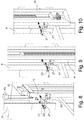
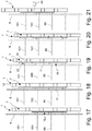
- the figures from 5 to 7 show a possible step of a climbing method, in which said climbing device 10 is anchored by said first portion 11 to a temporary top floor 100.
- said traction device 10 is then taken to an extended configuration, which makes it adapted to be anchored with said second portion 12 to a first top floor 101, arranged at a higher level than said temporary top floor 100.
- said traction device 10 is then taken to a contracted configuration anchored by its first portion 11 to said first upper floor 101.
- a climbing method comprises at least one step in which said first portion 11 and said second portion 12 of said traction device 10 are simultaneously anchored to the same building floor 3, e.g. to said first upper floor 101.
- a non-claimed climbing method comprises the following steps, provided in the following order:
Landscapes
- Engineering & Computer Science (AREA)
- Architecture (AREA)
- Mechanical Engineering (AREA)
- Civil Engineering (AREA)
- Structural Engineering (AREA)
- Conveying And Assembling Of Building Elements In Situ (AREA)
- Movable Scaffolding (AREA)
- Ladders (AREA)
Claims (12)
- Équipement (1) grimpant pour la construction d'un bâtiment ou d'un bâtiment en construction (2), ledit bâtiment en construction (2) comprenant une pluralité d'étages de bâtiment (3),
ledit équipement (1) grimpant comprenant au moins un échafaudage (7) adapté pour entourer au moins partiellement le périmètre d'au moins un étage de bâtiment (3) ;
et ledit échafaudage (7) comprenant au moins une plateforme de travail (8) adaptée pour former une surface praticable et adaptée pour faire saillie comme un porte-à-faux à partir dudit échafaudage (7) vers ledit bâtiment en construction (2), au moins une partie de ladite au moins une plateforme de travail (8) étant adaptée pour fermer l'espace ouvert entre ledit échafaudage (7) et ledit bâtiment en construction (2) ;
et ledit équipement (1) grimpant comprenant en outre un dispositif de traction (10) comprenant au moins une première portion (11) faisant partie intégrante dudit échafaudage (7) et au moins une seconde portion (12) reliée à ladite première portion (11) ;
ladite au moins une seconde portion (12) étant reliée de manière coulissante à ladite première portion (11) ; et
ladite au moins une première portion (11) comprenant au moins un premier élément d'accouplement (21) et ladite au moins une seconde portion (12) comprenant au moins un second élément d'accouplement (22) ;
et ledit premier élément d'accouplement (21) étant adapté pour saisir une première portion d'accouplement (31) dudit bâtiment en construction (2), et ledit second élément d'accouplement (22) étant adapté pour saisir une seconde portion d'accouplement (32) dudit bâtiment en construction (2) ; et ladite première portion d'accouplement (31) étant agencée à un niveau différent par rapport à ladite seconde portion d'accouplement (32) ; au moins soit ladite première portion d'accouplement (31) soit ladite seconde portion d'accouplement (32) comprend une goupille d'accouplement (33) adaptée pour être reçue dans un trou pratiqué dans un montant (9) du bâtiment en construction (2) ;
et ledit équipement (1) grimpant comprenant en outre un système mobile (15) adapté pour effectuer un mouvement relatif entre ladite première portion (11) et ladite seconde portion (12) dudit dispositif de traction (10) ;
et, lorsque ledit au moins un premier élément d'accouplement (21) est libéré de la portion d'accouplement respective dudit bâtiment en construction (2), ledit système mobile (15) étant adapté pour effectuer un mouvement relatif entre ladite première portion (11) et ladite seconde portion (12) dudit dispositif de traction (10), de façon à bouger ledit échafaudage (7) par un mouvement prédéterminé définissant une direction de mouvement relatif (X) ;
et
l'étendue dudit échafaudage (7) parallèle à la direction de mouvement relatif (X) étant plus grande que ladite première portion (11) du dispositif de traction (10), qui fait partie intégrante dudit échafaudage (7), d'une quantité prédéterminée (14), au moins égale à la hauteur d'un étage de bâtiment (90) ;
caractérisé en ce que
ledit premier élément d'accouplement (21) est relié de manière rotative à ladite première portion (11) dudit dispositif de traction (10) et ledit premier élément d'accouplement (21) est adapté pour faire saillie en porte-à-faux à partir de ladite première portion (11) dudit dispositif de traction (10), comme un plateau ; et ledit second élément d'accouplement (22) est relié de manière rotative à ladite seconde portion (12) dudit dispositif de traction (10) ; et ledit second élément d'accouplement (22) est adapté pour faire saillie en porte-à-faux à partir de ladite seconde portion (12) dudit dispositif de traction (10), comme un plateau ; et en ce que
ledit premier élément d'accouplement (21) et ledit second élément d'accouplement (22) comprennent chacun au moins un crochet (23), de façon à ce que ledit au moins un crochet (23) soit adapté pour être accouplé de manière libérable à ladite goupille d'accouplement (33) incluse dans ledit bâtiment en construction (2). - Équipement (1) selon la revendication 1, dans lequel ladite quantité prédéterminée (14) est au moins égale à la hauteur de deux étages de bâtiment, de façon à ce que ledit échafaudage (7) comprenne une portion en excès (17) dont l'étendue en hauteur est appropriée pour entourer un étage supérieur temporaire (100) et au moins une portion d'espace utile adaptée pour entourer un étage supérieur (101) et un autre étage supérieur (102) agencé à un niveau plus élevé que ledit premier étage supérieur (101) et adjacent audit premier étage supérieur (101).
- Équipement (1) selon l'une quelconque des revendications précédentes, dans lequel ladite plateforme de travail (8) est basculable, adaptée pour passer d'une position étendue, dans laquelle elle forme une surface praticable qui fait saillie comme un porte-à-faux à partir dudit échafaudage (7) vers ledit bâtiment en construction (2), et au moins une position rétractée, dans laquelle elle est contenue dans le jeu dudit échafaudage (7).
- Équipement (1) selon l'une quelconque des revendications précédentes, dans lequel ledit au moins un premier élément d'accouplement (21) est relié à un premier actionneur (41) pour le bouger entre une position d'accouplement dans laquelle il est ancré par rapport à ladite première portion d'accouplement (31), et une position de libération dans laquelle il n'est pas en contact avec ladite première portion d'accouplement (31), et dans lequel ledit second élément d'accouplement (22) est relié à un second actionneur (42) pour le bouger entre une position d'accouplement dans laquelle il est ancré par rapport à ladite seconde portion d'accouplement (32), et une position de libération dans laquelle il n'est pas en contact avec ladite seconde portion d'accouplement (32).
- Équipement (1) selon la revendication 4, dans lequel ledit premier actionneur (41) s'étend vers le haut à partir dudit premier élément d'accouplement (21) pour atteindre ladite première portion (11) du dispositif de traction (10), et dans lequel ledit second actionneur (42) s'étend vers le haut à partir dudit second élément d'accouplement (22) pour atteindre ladite première portion (12) du dispositif de traction (10).
- Équipement (1) selon l'une quelconque des revendications précédentes, dans lequel ledit échafaudage (7) est un échafaudage modulaire comprenant une pluralité d'unités (M) d'échafaudage modulaire pouvant être reliées pour former un échafaudage (7) ayant une étendue en hauteur prédéterminée, et dans lequel ladite pluralité d'unités (M) d'échafaudage modulaire peuvent être reliées pour former un échafaudage ayant une étendue prédéterminée autour dudit bâtiment en construction (2).
- Équipement (1) selon l'une quelconque des revendications précédentes, comprenant une pluralité desdits dispositifs de traction (10) et une pluralité desdits systèmes mobiles (15), repartis autour de la face extérieure dudit bâtiment en construction (2) et reliés à ladite pluralité desdits dispositifs de traction (10), et ladite pluralité de systèmes de traction (10) et ladite pluralité de systèmes mobiles (15) étant commandés d'une manière surveillée et à l'aide d'une rétroaction au moyen d'au moins des capteurs de déplacement de l'échafaudage (7) de façon à maintenir ledit échafaudage (7) au niveau souhaité ou à la hauteur souhaitée aussi bien lorsqu'il est immobile que lorsqu'il est mobile ; et ladite pluralité de systèmes de traction (10) et ladite pluralité de systèmes mobiles (15) étant commandés d'une manière surveillée et à l'aide d'une rétroaction au moyen d'au moins des capteurs d'inclinaison de l'échafaudage (7) de façon à maintenir ledit échafaudage (7) parfaitement horizontal aussi bien lorsqu'il est immobile que lorsqu'il est mobile.
- Équipement (1) selon l'une quelconque des revendications précédentes, dans lequel ledit dispositif de traction (10) comprend au moins une couche de matériau à faible frottement (13) interposée entre ladite première portion (11) du dispositif de traction (10) et ladite seconde portion (12) du dispositif de traction (10) pour faciliter le coulissement entre ladite première portion (11) et ladite seconde portion (12) du dispositif de traction (10).
- Équipement (1) selon l'une quelconque des revendications précédentes, dans lequel ledit échafaudage (7) comprend au moins un module d'ancrage (18) comprenant un dispositif d'ancrage par rapport à ladite première portion (11) dudit dispositif de traction (10) ; et dans lequel ledit échafaudage (7) comprend au moins un module de travail (19), qui peut être associé à au moins un module d'ancrage (18), et comprend au moins une surface praticable et définissant au moins un espace de travail adapté pour recevoir en toute sécurité un ou plusieurs opérateurs ; et dans lequel ledit module de travail (19) comprend au moins une plateforme de travail (9).
- Équipement (1) selon l'une quelconque des revendications précédentes, dans lequel ladite première portion (11) du dispositif de traction (10) comprend des guides coulissants formés mutuellement par rapport à des curseurs coulissants fournis sur ladite seconde portion (12) du dispositif de traction (10) ; ou dans lequel ladite seconde portion (12) du dispositif de traction (10) comprend des guides coulissants formés mutuellement par rapport à des curseurs coulissants fournis sur ladite première portion (11) du dispositif de traction (10).
- Équipement (1) selon l'une quelconque des revendications précédentes, dans lequel la hauteur d'un étage de bâtiment (90) est comprise entre 2 mètres et 4 mètres, et de préférence comprise entre 2,5 mètres et 3,5 mètres.
- Équipement (1) selon l'une quelconque des revendications précédentes, dans lequel ledit mouvement prédéterminé dudit échafaudage (7) est un mouvement d'élévation, de façon à ce que ledit mouvement soit dirigé vers le haut.
Applications Claiming Priority (2)
| Application Number | Priority Date | Filing Date | Title |
|---|---|---|---|
| ITUB2015A004872A ITUB20154872A1 (it) | 2015-10-27 | 2015-10-27 | Impianto di scalata e metodo per la costruzione di edifici |
| PCT/IB2016/056400 WO2017072654A1 (fr) | 2015-10-27 | 2016-10-25 | Équipement de surélévation et procédé de surélévation pour la construction de bâtiments |
Publications (2)
| Publication Number | Publication Date |
|---|---|
| EP3368730A1 EP3368730A1 (fr) | 2018-09-05 |
| EP3368730B1 true EP3368730B1 (fr) | 2021-03-31 |
Family
ID=55315554
Family Applications (1)
| Application Number | Title | Priority Date | Filing Date |
|---|---|---|---|
| EP16801580.8A Active EP3368730B1 (fr) | 2015-10-27 | 2016-10-25 | Équipement grimpant pour la construction de bâtiments |
Country Status (7)
| Country | Link |
|---|---|
| US (2) | US10036170B2 (fr) |
| EP (1) | EP3368730B1 (fr) |
| CN (1) | CN108431345B (fr) |
| CA (1) | CA3003340C (fr) |
| ES (1) | ES2878092T3 (fr) |
| IT (1) | ITUB20154872A1 (fr) |
| WO (1) | WO2017072654A1 (fr) |
Families Citing this family (17)
| Publication number | Priority date | Publication date | Assignee | Title |
|---|---|---|---|---|
| ITUB20154872A1 (it) * | 2015-10-27 | 2017-04-27 | Despe S P A | Impianto di scalata e metodo per la costruzione di edifici |
| DE102016205956A1 (de) * | 2016-04-08 | 2017-10-12 | Peri Gmbh | Selbstklettersystem, Selbstklettereinheit sowie Verfahren zum Umsetzen einer solchen Selbstklettereinheit an einem Betonbaukörper |
| DE102017217715A1 (de) | 2017-10-05 | 2019-04-11 | Peri Gmbh | Hydraulik-Anordnung mit vernetzten Hydraulikaggregaten sowie Kletterschalung und Verfahren zum Bewegen der Kletterschalung mit einer solchen Hydraulik-Anordnung |
| DE102018117727A1 (de) * | 2018-07-23 | 2020-01-23 | Peri Gmbh | Hubantrieb für ein schienengeführtes klettersystem |
| CN109162437B (zh) * | 2018-10-11 | 2023-07-14 | 上海建工一建集团有限公司 | 用于多筒钢板剪力墙的整体钢平台及其施工方法 |
| CN109372244B (zh) * | 2018-11-23 | 2024-05-28 | 成都嘉泽正达科技有限公司 | 脚手架防坠装置 |
| PL3899167T4 (pl) * | 2018-12-18 | 2025-12-01 | Inventio Ag | Urządzenie do placów budowy z deskowaniem wznoszącym i systemem dźwigowym |
| US11408188B1 (en) * | 2019-06-04 | 2022-08-09 | Peri Formwork Systems, Inc. | Suspended translating platform |
| CN111648598B (zh) * | 2020-08-10 | 2020-11-03 | 上海建工一建集团有限公司 | 爬升模架装置及其施工方法 |
| DE102020214454A1 (de) * | 2020-11-17 | 2022-05-19 | Doka Gmbh | Klettergerüst |
| CN113958108A (zh) * | 2020-11-25 | 2022-01-21 | 广州三叠纪元智能科技有限公司 | 电箱控制方法、电箱、服务器和存储介质 |
| CN112663912A (zh) * | 2021-01-04 | 2021-04-16 | 涂强(上海)智能科技有限公司 | 建筑外墙喷腻子设备及其刮腻子方法 |
| CN113216590B (zh) * | 2021-05-13 | 2022-09-30 | 中建一局集团建设发展有限公司 | 一种悬挑结构上挂座体系及施工方法 |
| US20220412105A1 (en) | 2021-06-25 | 2022-12-29 | Premform Limited | Climbing system for multi-level building construction |
| DE102021120441A1 (de) * | 2021-08-05 | 2023-02-09 | Peri Se | System zur Schalung eines Wandelementes mit einem Verbund aus einer Schalung und einem Gerüstabschnitt |
| DE102021120438A1 (de) * | 2021-08-05 | 2023-02-09 | Peri Se | System zur Schalung eines Wandelementes mit einem frei stehenden Gerüstabschnitt |
| CN115949218B (zh) * | 2023-02-13 | 2023-09-22 | 武汉建工集团股份有限公司 | 一种扩展式多功能集成施工空中造楼平台及其施工方法 |
Family Cites Families (28)
| Publication number | Priority date | Publication date | Assignee | Title |
|---|---|---|---|---|
| DE2361110A1 (de) * | 1973-12-07 | 1975-06-26 | Oesterr Doka Schalung | Kletterschalung fuer betonwaende |
| DE2921636C2 (de) * | 1979-05-28 | 1982-09-09 | Hünnebeck GmbH, 4030 Ratingen | Gerät mit Hubvorrichtung zum Klettern an einer Wand |
| FR2487892A1 (fr) * | 1980-08-01 | 1982-02-05 | Huennebeck Gmbh | Appareil a dispositif elevateur pour grimper le long d'une paroi, notamment pour echafaudage grimpant |
| NL8004572A (nl) * | 1980-08-12 | 1982-03-16 | Huennebeck Gmbh | Apparaat met hefinrichting voor het klimmen aan een wand. |
| JP3180203B2 (ja) | 1993-09-07 | 2001-06-25 | 大成建設株式会社 | 超高層構造物建設に用いる資材揚重組み立て装置 |
| JPH07189491A (ja) * | 1993-12-27 | 1995-07-28 | Taisei Corp | 高層構造物建設に用いる作業ステージせり上げ装置 |
| KR100260648B1 (ko) * | 1997-11-27 | 2000-12-01 | 노희상 | 건축 공사용 안전 펜스 |
| US6557817B2 (en) * | 2000-01-18 | 2003-05-06 | Wilian Holding Company | Wall climbing form hoist |
| JP4319780B2 (ja) | 2000-12-25 | 2009-08-26 | 大成建設株式会社 | 型枠装置及び構造物の連続施工方法 |
| US6494291B2 (en) * | 2001-04-27 | 2002-12-17 | Tatsuo Ono | Foldable scaffold device |
| FR2831578B1 (fr) * | 2001-10-29 | 2004-08-20 | Frenehard & Michaux Sa | Dispositif formant echafaudage suspendu a une facade d'un batiment |
| CN100351483C (zh) * | 2005-03-10 | 2007-11-28 | 深圳市特辰科技有限公司 | 一种整体提升爬模平台系统及其操作方法 |
| DE102005030335A1 (de) * | 2005-06-29 | 2007-01-04 | Peri Gmbh | Kletterzylinder einer Selbstkletterschalung |
| DE102005030336A1 (de) * | 2005-06-29 | 2007-01-04 | Peri Gmbh | Schienengeführtes Klettersystem |
| DE102005045527A1 (de) * | 2005-09-23 | 2007-04-19 | Doka Industrie Gmbh | Schutz- und Zugangsvorrichtung |
| DE102006019622A1 (de) * | 2006-04-25 | 2007-11-15 | Hek Manufacturing B.V. | Mastbühne sowie Verfahren zu deren Höhenverstellung |
| KR100841011B1 (ko) * | 2007-04-11 | 2008-06-24 | 금강공업 주식회사 | 중량물 승강장치 |
| DE102007026020A1 (de) * | 2007-06-04 | 2008-12-11 | Doka Industrie Gmbh | Selbstklettersystem und Verfahren zum Betonieren eines Unterzugs und/oder Montieren eines Fertigteils mittels eines Selbstklettersystems |
| KR100862275B1 (ko) | 2007-06-20 | 2008-10-09 | 주식회사 근하기공 | 고층건물 시공용 지씨에스 |
| CN101824904A (zh) * | 2009-03-05 | 2010-09-08 | 卢兴明 | 整体脚手架支撑升降方法及其双导轨双防坠液压提升整体脚手架 |
| PL2365159T3 (pl) | 2010-03-05 | 2013-07-31 | Ulma C Y E S Coop | Samowznoszący, obwodowy system zabezpieczania dla prac budowlanych w budynkach |
| KR20130077176A (ko) | 2011-12-29 | 2013-07-09 | 고려대학교 산학협력단 | 고층 빌딩의 철골 구조물의 자동화 시공 시스템 |
| US9217255B2 (en) * | 2012-11-30 | 2015-12-22 | Chicago Bridge & Iron Company | Self-jacking scaffold for large cylindrical tanks |
| CN203531344U (zh) * | 2013-10-18 | 2014-04-09 | 浙江固华脚手架工程有限公司 | 工具式脚手架 |
| ES2621479T3 (es) * | 2013-11-12 | 2017-07-04 | Ulma C Y E, S. Coop. | Sistema autotrepante para andamios en obras de construcción de edificios |
| CA2838259C (fr) * | 2013-12-30 | 2020-08-18 | International Chimney Corporation | Systeme d'echafaudage |
| CN204662951U (zh) * | 2015-05-12 | 2015-09-23 | 浙江欣捷建设有限公司 | 高塔液压爬架 |
| ITUB20154872A1 (it) * | 2015-10-27 | 2017-04-27 | Despe S P A | Impianto di scalata e metodo per la costruzione di edifici |
-
2015
- 2015-10-27 IT ITUB2015A004872A patent/ITUB20154872A1/it unknown
-
2016
- 2016-10-25 CN CN201680076097.1A patent/CN108431345B/zh active Active
- 2016-10-25 CA CA3003340A patent/CA3003340C/fr active Active
- 2016-10-25 ES ES16801580T patent/ES2878092T3/es active Active
- 2016-10-25 WO PCT/IB2016/056400 patent/WO2017072654A1/fr not_active Ceased
- 2016-10-25 EP EP16801580.8A patent/EP3368730B1/fr active Active
-
2017
- 2017-04-28 US US15/581,465 patent/US10036170B2/en active Active
-
2018
- 2018-05-17 US US15/982,574 patent/US10633874B2/en active Active
Non-Patent Citations (1)
| Title |
|---|
| None * |
Also Published As
| Publication number | Publication date |
|---|---|
| US10633874B2 (en) | 2020-04-28 |
| WO2017072654A1 (fr) | 2017-05-04 |
| CN108431345B (zh) | 2021-04-16 |
| US20170226757A1 (en) | 2017-08-10 |
| EP3368730A1 (fr) | 2018-09-05 |
| CA3003340C (fr) | 2023-10-24 |
| CN108431345A (zh) | 2018-08-21 |
| US20180266124A1 (en) | 2018-09-20 |
| US10036170B2 (en) | 2018-07-31 |
| HK1253416A1 (en) | 2019-06-14 |
| ITUB20154872A1 (it) | 2017-04-27 |
| ES2878092T3 (es) | 2021-11-18 |
| CA3003340A1 (fr) | 2017-05-04 |
Similar Documents
| Publication | Publication Date | Title |
|---|---|---|
| EP3368730B1 (fr) | Équipement grimpant pour la construction de bâtiments | |
| ES2968201T3 (es) | Accionamiento de elevación para un sistema trepador guiado por carriles y procedimiento para el trepado de un sistema trepador guiado por carriles | |
| US20220307276A1 (en) | Self-climbing system, self-climbing unit and method for moving such a self-climbing unit on a concrete building structure | |
| US5645395A (en) | Building crane apparatus climbable on building walls | |
| US20120168251A1 (en) | Self-climbing hoist, deck and scaffold platform system | |
| US20190194957A1 (en) | Telescoping Break-Away Canopy Assembly | |
| CN113167072A (zh) | 具有爬升模板和升降机系统的建筑工地设备 | |
| CN1997801A (zh) | 用于在建筑物的高度上提升重物或个人的平台支撑设备 | |
| RU2011141929A (ru) | Передвижная модульная система строительных лесов для строительных работ и способ ее установки | |
| CN104929353A (zh) | 可拆卸楼梯式电梯井自动爬升操作平台 | |
| CN206233541U (zh) | 一种用于超高层建筑施工的内顶外爬式模架施工平台 | |
| HK1253416B (en) | Climbing equipment for the construction of buildings | |
| NZ242874A (en) | Cantilevered and adjustably suspended worker's staging or platform with jack devices exteriorly of structure's wall | |
| KR102585356B1 (ko) | 임베드플레이트 시공이 용이한 초고층 엘리베이터용 시스템 폼 장치 및 이를 이용한 초고층 엘리베이터용 임베드플레이트 시공방법 | |
| JP4011722B2 (ja) | 吊り階段 | |
| AU2008323613A1 (en) | Perimeter screening system | |
| RU198229U1 (ru) | Передвижная лестница для купольного здания | |
| JPH07317304A (ja) | 外部被覆体およびその盛り替え方法 | |
| JP7390113B2 (ja) | 既存建物への乗り込み用構造物 | |
| JP2024048117A (ja) | 工事用エレベータ | |
| EP3816083A1 (fr) | Procédure d'ensemble descendant de systèmes d'élévation et mât pré-tendu | |
| JPS63110364A (ja) | リフト用蓮台のクライミング方法及び装置 | |
| HK40046685A (en) | Building site device having a climbing formwork and an elevator system | |
| TR201708783A2 (tr) | GPS (GLOBAL POSITIONING SYSTEM) KULLANARAK KENDİ KENDİNİ KONUMLANDIRAN OTONOM HİDROMEKANİK TIRMANIR 3-BOYUTLU BETON ve ÇELİK/KOMPOZİT BASKI SİSTEMİ | |
| HK40000833B (en) | Self-climbing system, self-climbing unit and method for moving such a self-climbing unit on a concrete building structure |
Legal Events
| Date | Code | Title | Description |
|---|---|---|---|
| STAA | Information on the status of an ep patent application or granted ep patent |
Free format text: STATUS: UNKNOWN |
|
| STAA | Information on the status of an ep patent application or granted ep patent |
Free format text: STATUS: THE INTERNATIONAL PUBLICATION HAS BEEN MADE |
|
| PUAI | Public reference made under article 153(3) epc to a published international application that has entered the european phase |
Free format text: ORIGINAL CODE: 0009012 |
|
| STAA | Information on the status of an ep patent application or granted ep patent |
Free format text: STATUS: REQUEST FOR EXAMINATION WAS MADE |
|
| 17P | Request for examination filed |
Effective date: 20180524 |
|
| AK | Designated contracting states |
Kind code of ref document: A1 Designated state(s): AL AT BE BG CH CY CZ DE DK EE ES FI FR GB GR HR HU IE IS IT LI LT LU LV MC MK MT NL NO PL PT RO RS SE SI SK SM TR |
|
| AX | Request for extension of the european patent |
Extension state: BA ME |
|
| DAV | Request for validation of the european patent (deleted) | ||
| DAX | Request for extension of the european patent (deleted) | ||
| REG | Reference to a national code |
Ref country code: HK Ref legal event code: DE Ref document number: 1253416 Country of ref document: HK |
|
| GRAJ | Information related to disapproval of communication of intention to grant by the applicant or resumption of examination proceedings by the epo deleted |
Free format text: ORIGINAL CODE: EPIDOSDIGR1 |
|
| STAA | Information on the status of an ep patent application or granted ep patent |
Free format text: STATUS: GRANT OF PATENT IS INTENDED |
|
| GRAP | Despatch of communication of intention to grant a patent |
Free format text: ORIGINAL CODE: EPIDOSNIGR1 |
|
| INTG | Intention to grant announced |
Effective date: 20210113 |
|
| RAP1 | Party data changed (applicant data changed or rights of an application transferred) |
Owner name: DESPE S.P.A. |
|
| GRAS | Grant fee paid |
Free format text: ORIGINAL CODE: EPIDOSNIGR3 |
|
| GRAA | (expected) grant |
Free format text: ORIGINAL CODE: 0009210 |
|
| STAA | Information on the status of an ep patent application or granted ep patent |
Free format text: STATUS: THE PATENT HAS BEEN GRANTED |
|
| AK | Designated contracting states |
Kind code of ref document: B1 Designated state(s): AL AT BE BG CH CY CZ DE DK EE ES FI FR GB GR HR HU IE IS IT LI LT LU LV MC MK MT NL NO PL PT RO RS SE SI SK SM TR |
|
| REG | Reference to a national code |
Ref country code: GB Ref legal event code: FG4D Ref country code: CH Ref legal event code: EP |
|
| RIN1 | Information on inventor provided before grant (corrected) |
Inventor name: PANSERI, STEFANO Inventor name: PANSERI, GIUSEPPE Inventor name: PANSERI, ROBERTO |
|
| REG | Reference to a national code |
Ref country code: AT Ref legal event code: REF Ref document number: 1377079 Country of ref document: AT Kind code of ref document: T Effective date: 20210415 |
|
| REG | Reference to a national code |
Ref country code: DE Ref legal event code: R096 Ref document number: 602016055326 Country of ref document: DE |
|
| REG | Reference to a national code |
Ref country code: IE Ref legal event code: FG4D |
|
| REG | Reference to a national code |
Ref country code: NL Ref legal event code: FP |
|
| REG | Reference to a national code |
Ref country code: LT Ref legal event code: MG9D |
|
| PG25 | Lapsed in a contracting state [announced via postgrant information from national office to epo] |
Ref country code: BG Free format text: LAPSE BECAUSE OF FAILURE TO SUBMIT A TRANSLATION OF THE DESCRIPTION OR TO PAY THE FEE WITHIN THE PRESCRIBED TIME-LIMIT Effective date: 20210630 Ref country code: HR Free format text: LAPSE BECAUSE OF FAILURE TO SUBMIT A TRANSLATION OF THE DESCRIPTION OR TO PAY THE FEE WITHIN THE PRESCRIBED TIME-LIMIT Effective date: 20210331 Ref country code: FI Free format text: LAPSE BECAUSE OF FAILURE TO SUBMIT A TRANSLATION OF THE DESCRIPTION OR TO PAY THE FEE WITHIN THE PRESCRIBED TIME-LIMIT Effective date: 20210331 Ref country code: NO Free format text: LAPSE BECAUSE OF FAILURE TO SUBMIT A TRANSLATION OF THE DESCRIPTION OR TO PAY THE FEE WITHIN THE PRESCRIBED TIME-LIMIT Effective date: 20210630 |
|
| PG25 | Lapsed in a contracting state [announced via postgrant information from national office to epo] |
Ref country code: RS Free format text: LAPSE BECAUSE OF FAILURE TO SUBMIT A TRANSLATION OF THE DESCRIPTION OR TO PAY THE FEE WITHIN THE PRESCRIBED TIME-LIMIT Effective date: 20210331 Ref country code: LV Free format text: LAPSE BECAUSE OF FAILURE TO SUBMIT A TRANSLATION OF THE DESCRIPTION OR TO PAY THE FEE WITHIN THE PRESCRIBED TIME-LIMIT Effective date: 20210331 Ref country code: SE Free format text: LAPSE BECAUSE OF FAILURE TO SUBMIT A TRANSLATION OF THE DESCRIPTION OR TO PAY THE FEE WITHIN THE PRESCRIBED TIME-LIMIT Effective date: 20210331 |
|
| REG | Reference to a national code |
Ref country code: AT Ref legal event code: MK05 Ref document number: 1377079 Country of ref document: AT Kind code of ref document: T Effective date: 20210331 |
|
| PG25 | Lapsed in a contracting state [announced via postgrant information from national office to epo] |
Ref country code: SM Free format text: LAPSE BECAUSE OF FAILURE TO SUBMIT A TRANSLATION OF THE DESCRIPTION OR TO PAY THE FEE WITHIN THE PRESCRIBED TIME-LIMIT Effective date: 20210331 Ref country code: AT Free format text: LAPSE BECAUSE OF FAILURE TO SUBMIT A TRANSLATION OF THE DESCRIPTION OR TO PAY THE FEE WITHIN THE PRESCRIBED TIME-LIMIT Effective date: 20210331 Ref country code: CZ Free format text: LAPSE BECAUSE OF FAILURE TO SUBMIT A TRANSLATION OF THE DESCRIPTION OR TO PAY THE FEE WITHIN THE PRESCRIBED TIME-LIMIT Effective date: 20210331 Ref country code: EE Free format text: LAPSE BECAUSE OF FAILURE TO SUBMIT A TRANSLATION OF THE DESCRIPTION OR TO PAY THE FEE WITHIN THE PRESCRIBED TIME-LIMIT Effective date: 20210331 Ref country code: LT Free format text: LAPSE BECAUSE OF FAILURE TO SUBMIT A TRANSLATION OF THE DESCRIPTION OR TO PAY THE FEE WITHIN THE PRESCRIBED TIME-LIMIT Effective date: 20210331 |
|
| REG | Reference to a national code |
Ref country code: ES Ref legal event code: FG2A Ref document number: 2878092 Country of ref document: ES Kind code of ref document: T3 Effective date: 20211118 |
|
| PG25 | Lapsed in a contracting state [announced via postgrant information from national office to epo] |
Ref country code: IS Free format text: LAPSE BECAUSE OF FAILURE TO SUBMIT A TRANSLATION OF THE DESCRIPTION OR TO PAY THE FEE WITHIN THE PRESCRIBED TIME-LIMIT Effective date: 20210731 Ref country code: PT Free format text: LAPSE BECAUSE OF FAILURE TO SUBMIT A TRANSLATION OF THE DESCRIPTION OR TO PAY THE FEE WITHIN THE PRESCRIBED TIME-LIMIT Effective date: 20210802 Ref country code: PL Free format text: LAPSE BECAUSE OF FAILURE TO SUBMIT A TRANSLATION OF THE DESCRIPTION OR TO PAY THE FEE WITHIN THE PRESCRIBED TIME-LIMIT Effective date: 20210331 Ref country code: RO Free format text: LAPSE BECAUSE OF FAILURE TO SUBMIT A TRANSLATION OF THE DESCRIPTION OR TO PAY THE FEE WITHIN THE PRESCRIBED TIME-LIMIT Effective date: 20210331 Ref country code: SK Free format text: LAPSE BECAUSE OF FAILURE TO SUBMIT A TRANSLATION OF THE DESCRIPTION OR TO PAY THE FEE WITHIN THE PRESCRIBED TIME-LIMIT Effective date: 20210331 |
|
| REG | Reference to a national code |
Ref country code: DE Ref legal event code: R097 Ref document number: 602016055326 Country of ref document: DE |
|
| PG25 | Lapsed in a contracting state [announced via postgrant information from national office to epo] |
Ref country code: AL Free format text: LAPSE BECAUSE OF FAILURE TO SUBMIT A TRANSLATION OF THE DESCRIPTION OR TO PAY THE FEE WITHIN THE PRESCRIBED TIME-LIMIT Effective date: 20210331 Ref country code: DK Free format text: LAPSE BECAUSE OF FAILURE TO SUBMIT A TRANSLATION OF THE DESCRIPTION OR TO PAY THE FEE WITHIN THE PRESCRIBED TIME-LIMIT Effective date: 20210331 |
|
| PLBE | No opposition filed within time limit |
Free format text: ORIGINAL CODE: 0009261 |
|
| STAA | Information on the status of an ep patent application or granted ep patent |
Free format text: STATUS: NO OPPOSITION FILED WITHIN TIME LIMIT |
|
| 26N | No opposition filed |
Effective date: 20220104 |
|
| PG25 | Lapsed in a contracting state [announced via postgrant information from national office to epo] |
Ref country code: IS Free format text: LAPSE BECAUSE OF FAILURE TO SUBMIT A TRANSLATION OF THE DESCRIPTION OR TO PAY THE FEE WITHIN THE PRESCRIBED TIME-LIMIT Effective date: 20210731 |
|
| PG25 | Lapsed in a contracting state [announced via postgrant information from national office to epo] |
Ref country code: LU Free format text: LAPSE BECAUSE OF NON-PAYMENT OF DUE FEES Effective date: 20211025 |
|
| PG25 | Lapsed in a contracting state [announced via postgrant information from national office to epo] |
Ref country code: IE Free format text: LAPSE BECAUSE OF NON-PAYMENT OF DUE FEES Effective date: 20211025 |
|
| PG25 | Lapsed in a contracting state [announced via postgrant information from national office to epo] |
Ref country code: HU Free format text: LAPSE BECAUSE OF FAILURE TO SUBMIT A TRANSLATION OF THE DESCRIPTION OR TO PAY THE FEE WITHIN THE PRESCRIBED TIME-LIMIT; INVALID AB INITIO Effective date: 20161025 |
|
| PG25 | Lapsed in a contracting state [announced via postgrant information from national office to epo] |
Ref country code: CY Free format text: LAPSE BECAUSE OF FAILURE TO SUBMIT A TRANSLATION OF THE DESCRIPTION OR TO PAY THE FEE WITHIN THE PRESCRIBED TIME-LIMIT Effective date: 20210331 |
|
| PG25 | Lapsed in a contracting state [announced via postgrant information from national office to epo] |
Ref country code: GR Free format text: LAPSE BECAUSE OF FAILURE TO SUBMIT A TRANSLATION OF THE DESCRIPTION OR TO PAY THE FEE WITHIN THE PRESCRIBED TIME-LIMIT Effective date: 20210331 |
|
| PG25 | Lapsed in a contracting state [announced via postgrant information from national office to epo] |
Ref country code: MK Free format text: LAPSE BECAUSE OF FAILURE TO SUBMIT A TRANSLATION OF THE DESCRIPTION OR TO PAY THE FEE WITHIN THE PRESCRIBED TIME-LIMIT Effective date: 20210331 |
|
| PG25 | Lapsed in a contracting state [announced via postgrant information from national office to epo] |
Ref country code: MT Free format text: LAPSE BECAUSE OF FAILURE TO SUBMIT A TRANSLATION OF THE DESCRIPTION OR TO PAY THE FEE WITHIN THE PRESCRIBED TIME-LIMIT Effective date: 20210331 |
|
| PGFP | Annual fee paid to national office [announced via postgrant information from national office to epo] |
Ref country code: NL Payment date: 20250925 Year of fee payment: 10 Ref country code: IT Payment date: 20250806 Year of fee payment: 10 |
|
| PGFP | Annual fee paid to national office [announced via postgrant information from national office to epo] |
Ref country code: FR Payment date: 20250930 Year of fee payment: 10 |
|
| REG | Reference to a national code |
Ref country code: CH Ref legal event code: U11 Free format text: ST27 STATUS EVENT CODE: U-0-0-U10-U11 (AS PROVIDED BY THE NATIONAL OFFICE) Effective date: 20251101 |
|
| PGFP | Annual fee paid to national office [announced via postgrant information from national office to epo] |
Ref country code: DE Payment date: 20251027 Year of fee payment: 10 |
|
| PGFP | Annual fee paid to national office [announced via postgrant information from national office to epo] |
Ref country code: GB Payment date: 20251022 Year of fee payment: 10 |
|
| PGFP | Annual fee paid to national office [announced via postgrant information from national office to epo] |
Ref country code: MC Payment date: 20251023 Year of fee payment: 10 |
|
| PGFP | Annual fee paid to national office [announced via postgrant information from national office to epo] |
Ref country code: TR Payment date: 20251006 Year of fee payment: 10 Ref country code: BE Payment date: 20251021 Year of fee payment: 10 |
|
| PGFP | Annual fee paid to national office [announced via postgrant information from national office to epo] |
Ref country code: CH Payment date: 20251101 Year of fee payment: 10 |
|
| PGFP | Annual fee paid to national office [announced via postgrant information from national office to epo] |
Ref country code: ES Payment date: 20251103 Year of fee payment: 10 |