EP3369874B1 - Modularer aufgeständerter boden mit eingebetteten heizelementen - Google Patents
Modularer aufgeständerter boden mit eingebetteten heizelementen Download PDFInfo
- Publication number
- EP3369874B1 EP3369874B1 EP17425022.5A EP17425022A EP3369874B1 EP 3369874 B1 EP3369874 B1 EP 3369874B1 EP 17425022 A EP17425022 A EP 17425022A EP 3369874 B1 EP3369874 B1 EP 3369874B1
- Authority
- EP
- European Patent Office
- Prior art keywords
- module
- panel
- per
- manner
- modules
- Prior art date
- Legal status (The legal status is an assumption and is not a legal conclusion. Google has not performed a legal analysis and makes no representation as to the accuracy of the status listed.)
- Active
Links
Images




Classifications
-
- E—FIXED CONSTRUCTIONS
- E04—BUILDING
- E04F—FINISHING WORK ON BUILDINGS, e.g. STAIRS, FLOORS
- E04F15/00—Flooring
- E04F15/02—Flooring or floor layers composed of a number of similar elements
- E04F15/024—Sectional false floors, e.g. computer floors
- E04F15/02405—Floor panels
-
- E—FIXED CONSTRUCTIONS
- E04—BUILDING
- E04F—FINISHING WORK ON BUILDINGS, e.g. STAIRS, FLOORS
- E04F15/00—Flooring
- E04F15/02—Flooring or floor layers composed of a number of similar elements
- E04F15/024—Sectional false floors, e.g. computer floors
- E04F15/02447—Supporting structures
- E04F15/02452—Details of junctions between the supporting structures and the panels or a panel-supporting framework
-
- E—FIXED CONSTRUCTIONS
- E04—BUILDING
- E04F—FINISHING WORK ON BUILDINGS, e.g. STAIRS, FLOORS
- E04F15/00—Flooring
- E04F15/02—Flooring or floor layers composed of a number of similar elements
- E04F15/024—Sectional false floors, e.g. computer floors
- E04F15/02447—Supporting structures
- E04F15/02464—Height adjustable elements for supporting the panels or a panel-supporting framework
- E04F15/0247—Screw jacks
-
- F—MECHANICAL ENGINEERING; LIGHTING; HEATING; WEAPONS; BLASTING
- F24—HEATING; RANGES; VENTILATING
- F24D—DOMESTIC- OR SPACE-HEATING SYSTEMS, e.g. CENTRAL HEATING SYSTEMS; DOMESTIC HOT-WATER SUPPLY SYSTEMS; ELEMENTS OR COMPONENTS THEREFOR
- F24D3/00—Hot-water central heating systems
- F24D3/12—Tube and panel arrangements for ceiling, wall, or underfloor heating
- F24D3/122—Details
- F24D3/127—Mechanical connections between panels
-
- F—MECHANICAL ENGINEERING; LIGHTING; HEATING; WEAPONS; BLASTING
- F24—HEATING; RANGES; VENTILATING
- F24D—DOMESTIC- OR SPACE-HEATING SYSTEMS, e.g. CENTRAL HEATING SYSTEMS; DOMESTIC HOT-WATER SUPPLY SYSTEMS; ELEMENTS OR COMPONENTS THEREFOR
- F24D3/00—Hot-water central heating systems
- F24D3/12—Tube and panel arrangements for ceiling, wall, or underfloor heating
- F24D3/14—Tube and panel arrangements for ceiling, wall, or underfloor heating incorporated in a ceiling, wall or floor
- F24D3/141—Tube mountings specially adapted therefor
- F24D3/142—Tube mountings specially adapted therefor integrated in prefab construction elements
-
- F—MECHANICAL ENGINEERING; LIGHTING; HEATING; WEAPONS; BLASTING
- F24—HEATING; RANGES; VENTILATING
- F24D—DOMESTIC- OR SPACE-HEATING SYSTEMS, e.g. CENTRAL HEATING SYSTEMS; DOMESTIC HOT-WATER SUPPLY SYSTEMS; ELEMENTS OR COMPONENTS THEREFOR
- F24D3/00—Hot-water central heating systems
- F24D3/12—Tube and panel arrangements for ceiling, wall, or underfloor heating
- F24D3/14—Tube and panel arrangements for ceiling, wall, or underfloor heating incorporated in a ceiling, wall or floor
- F24D3/148—Tube and panel arrangements for ceiling, wall, or underfloor heating incorporated in a ceiling, wall or floor with heat spreading plates
-
- F—MECHANICAL ENGINEERING; LIGHTING; HEATING; WEAPONS; BLASTING
- F24—HEATING; RANGES; VENTILATING
- F24D—DOMESTIC- OR SPACE-HEATING SYSTEMS, e.g. CENTRAL HEATING SYSTEMS; DOMESTIC HOT-WATER SUPPLY SYSTEMS; ELEMENTS OR COMPONENTS THEREFOR
- F24D2220/00—Components of central heating installations excluding heat sources
- F24D2220/20—Heat consumers
- F24D2220/2081—Floor or wall heating panels
-
- Y—GENERAL TAGGING OF NEW TECHNOLOGICAL DEVELOPMENTS; GENERAL TAGGING OF CROSS-SECTIONAL TECHNOLOGIES SPANNING OVER SEVERAL SECTIONS OF THE IPC; TECHNICAL SUBJECTS COVERED BY FORMER USPC CROSS-REFERENCE ART COLLECTIONS [XRACs] AND DIGESTS
- Y02—TECHNOLOGIES OR APPLICATIONS FOR MITIGATION OR ADAPTATION AGAINST CLIMATE CHANGE
- Y02B—CLIMATE CHANGE MITIGATION TECHNOLOGIES RELATED TO BUILDINGS, e.g. HOUSING, HOUSE APPLIANCES OR RELATED END-USER APPLICATIONS
- Y02B30/00—Energy efficient heating, ventilation or air conditioning [HVAC]
Definitions
- the present invention relates to the technical field concerning the construction of raised walkable surfaces, for example in the form of a raised screed.
- the invention refers to a raised walkable surface, for example a screed, constructed in such a manner so as to result in being fully assemblable/disassemblable, thus allowing also an easy access to the underlying surface, having heating elements integrated in itself.
- screed is the constructive horizontal element which is used to achieve one or more of the following purposes: flattening a surface, thus making it perfectly flat; distributing the load of the elements above; receiving the final flooring.
- the screed thickness is variable depending on the ambient type (for example, inside a building can be comprised between 4 and 8 cm). Its purpose is to make the underlying concrete substrate flat (loft or flooring), secondly, it is necessary to contain pipes and service cables. If the flooring above (ceramics, stone or wood) is laid by gluing, it is exactly on the screed that the glue is laid.
- the screed is therefore poured in place and generally consists of three materials used in appropriate proportions: cement, aggregate (sand and/or gravel, for example) and water.
- cement cement
- aggregate sand and/or gravel, for example
- water water
- the dose of the various elements varies depending on the external environment and on the location of it (internal or external, for civil or industrial purpose). Quite often additive or other materials are added to the typical ones (common examples are polystyrene, used to lighten screed, or quartz, used to smooth it or make it more tough).
- an iron net can be used, as in the case of concrete lofts.
- each module is made by a simple carrying panel placed on supporting foot, so as to make it raised. In this way, the space between the panel and the carrying level creates the housing of potential plant design.
- panels are simply placed side by side each other on supporting feet but not fixed at all, and, if on one side it simplifies their mobility, on the other side it can raise some stability issues.
- Other locking systems can provide glue which makes the installation longer and obviously makes more difficult the mobility of the module for maintenance services.
- such system of modular screeds does not integrate any heating system which has to be provided apart in the gap space that is formed in the installation and requiring an additional assembly action to be provided before the installation of the screed modules.
- the aim of the present invention is to provide a module which allows an easy accessibility to the underlying surface, thus resulting in being easily disassemblable but also stable at the same time.
- the aim of the present invention is to provide a module which integrates in itself a heating system, which guarantees a fixing system at the same time, both of modules with one other and of various elements composing each module, being applicable/removable rapidly, in such a manner so as to allow an immediate access to parts of the module itself or to allow a rapid removal of a module and a rapid re-positioning of itself as well.
- Such module (1) comprises a top panel (10) suitable to form a walkable surface.
- the top panel can therefore be subsequently covered with finishing elements or integrate in itself such finishing elements forming the final flooring (for example a parquet).
- the module (1) further comprises the following elements:
- connecting means (100) are provided applicable, for example, following the assembly of the module, configured in such a manner so as to exert a mechanical action according to an approaching direction of the top panel (10) to the bottom panel (20).
- Such connecting means are further configured in such a manner so as to result in being removable (that is fastening connecting means) in such a manner that, in correspondence to their removal, one or more of said elements constituting the module result in being disassemblable each other.
- the module integrates in itself a heating element together with a thermally insulating element arranged to facilitate the heat irradiation upward.
- the heating element allows to irradiate heat and such a kind of configuration allows a good heat irradiation towards the walkable surface, thus simply creating a module assemblable with other modules for creating a screed able to emit heat. Therefore, heating systems are not required to be installed below the raised screed as separated element.
- the module forming the screed, or the surface in general can be installed on a potential raised support, also with the smallest heights, as the potential heating system is integrated into the module itself and has not to be integrated into the space that is formed between the screed and the carrying level.
- this solution allows a remarkable time saving during the assembly, as it does not require first the installation of the heating system and then the installation of the overhead screed.
- the used connecting means are of the mechanical type, therefore they do not provide glues, and, for this reason, they are easily removable and once removed, they allow an easy removal of the parts of each module, if this is considered necessary for the maintenance.
- a surface of insulating material (30), in form of a panel, is placed above the bottom panel (20) and with the heating device (50) comprised between the top panel (10) and such a surface of insulating material (30).
- This solution has the advantage of optimizing the heat irradiation towards the flooring in use to be stepped on, that is the top surface.
- the above-described module is of the raised type, as means are provided to raise it to the desired level in respect to the supporting surface.
- Such means are advantageously adjustable in height.
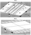
- Figure 1 shows a module suitable for creating a raised screed or of a flooring in general, and therefore of a walkable surface, according to the present invention.
- screw means any walkable surface, and therefore also a modular flooring in general and the term “screed” is not to be considered with limiting meaning.
- the raised screed does not require the use of glues for its assembly and therefore it is fully disassemblable and/or re-assemblable.
- the system of raised support that is the system allowing to make the height of the screed itself variable from the ground, allows the purpose of connecting element, by stacking one another the element of the single module, and at the same time, by fixing a module to an adjacent one for the assembly of the screed.
- such a raised screed is composed by modules (one or more than one). Obviously, in the case of more than one module, these can be placed side by side, in such a manner so as to cover a predetermined area assembling the screed.
- modules are for example highlighted in figures 1, 2 , 3 and a module can be put side by side to another one without requiring the use of glue. For this reason, the single module, if required, can be removed for accessing to the underlying surface, for example in order to inspect predetermined areas.
- Each module in turn, as again described in more detail in figures 1 to 3 , is made of more overlapping elements and obviously, easily disassemblable one another, as, in the preferred embodiment of the invention, the same fixing system that fix a module to its adjacent one are advantageously used also to stack the elements of the module at the same time. This entails that each part of the module can be easily removed and replaced, for example in the case of repairing.
- Fixing systems as explained further, are of the mechanic type and exert a pressure in the axial direction and are thus defined of the axial type.
- the invention provides at least an axial-action system which performs the function of stacking and fixing a module to an adjacent module.
- Figure 1 or figure 2 therefore, show a module 1 which can be put side by side with other identical modules.
- the single module provides two external panels (10, 20), that is a top panel 10 and a bottom panel 20.
- the top panel 10 is a carrying panel, for example made of Gres, marble or similar materials.
- the bottom panel is equal to the top one, that is a carrying one.
- the top panel 10 forms the walkable surface and further finishing elements can be applied on it, such as tiles, parquet, etc. Therefore, the finishing elements can be bought separately depending on personal tastes and can be applied with glues and adhesives commonly used in the technical field, once the whole screed is assembled.
- the top surface 10 can integrate in itself finishing elements (for example Gres, PVC, parquet, marble, etc.), shaped according to the form of the top surface, or it can be the end material (with potential decorative processing).
- finishing elements for example Gres, PVC, parquet, marble, etc.
- the insulating panel 30 is processed in such a manner so as to form a series of corridors engraved on its surface that can intersect one another with right angle.
- figure 5 shows very well such a shape, being removed the top panel.
- the figure shows for each panel 30 a series of longitudinal parallel one another corridors 31 and a series of transverse corridors 31, intersecting the longitudinal corridors. The same can be seen also in figure 3 .
- the corridors are of such a size that they can contain the provided pipes inside them, that is the heating system.
- the pipes are necessary for the passage of a warm fluid (for example, liquid like water as inside conventional heating radiators).
- a warm fluid for example, liquid like water as inside conventional heating radiators.
- Such pipes are connected to a collector and from the collector to a pump and a normal boiler which heats up the circulating water.
- the pipe can be one unique flexible pipe passing along corridors following a set path.
- each single module allows the repairing/replacement also of segments of broken pipes.
- Figure 5 shows four modules placed side by side and wherein the top panel has been removed. In this way, the passage of pipes provided with circular connecting parts, joining rectilinear segments each other, can be seen very well.
- the panel 30 of insulating material (for example, in the case of Styrofoam or polystyrene) can be advantageously made in a mould, thus resulting in rapid manufacturing and low-cost.
- the top layer is made of aluminum, metal in general or other materials with good thermal-conductive characteristics.
- the purpose of the layer 40 is to irradiate heat upwards, that is towards the walkable panel 20 and to level out the spreading onto the top panel.
- the insulating layer 30 is necessary to avoid heat loss downwards.
- the supporting axis 101 provides a duct 103 having a supporting base 104, for example circular one, in such a manner that such a duct can be placed firmly on a surface (that is the flooring), thus resulting emerging upwards from it.
- the duct 103 is axially hollow, in such a manner so as to hold the proper support component 105 of the module, that is the surface 106 in contact with the bottom panel.
- a support component 105 is formed by said surface 106 and an axis 107 configured to insert itself in the canal formed by duct 103.
- the overall heights of the whole axis 101 is easily adjustable, depending on needs, by varying the raising heights of the modules from the ground.
- the axis 107 is axially holed with a hole 109 leading to the surface 106.
- the screw 102 is insertable and screwable in the hole 109 which provides a complementary threading, compacting and clamping the elements that intersects as the latter ones are clamped between the enlarged head 102' of the screw and the support surface 106.
- a module is, for example, perforated at its center point with a through hole, once leaning on the plate 106 in such a manner that its hole is aligned with the hole 109, it is enough to pass the screw up to intercepting the hole 109 and clamping the screw so that this stacks the module, namely its elements that compose it.
- maintenance for example, inspection of the piping 50, it is sufficient to loosen and remove the screw to detach the top panel, the layer and the other elements if necessary.
- a head gasket 108 which leans on the surface 106 (thus interposed between the surface 106 and the bottom panel). It is made of plastic and provided with spacing wings for facilitating the alignment of the four edges that are leaning on the same surface and to avoid possible creaking.
- a suitable processing or shape of the perimeter of each module means that the axial clamping system can effectively perform the locking function of a module with an adjacent module and, at the same time, fix one another the elements forming the module itself and described above.
- top panel 10 and the bottom panel 20 of each module have a finishing in correspondence of their four corners that is very well highlighted in figure 7 .
- the finishing consists of a removal of material in correspondence of the four corners.
- That removal forms an angular countersink 111 (ninety-degrees angle) in correspondence of the corners. It penetrates into the thickness of such a panel for such a quantity as to hold the thickness of the washer 110 and therefore of the head of the screw 102' that in this way, through the washer, is flush with the panel.
- the angle is removed so as to generate a flat side 113.
- the side 113 is preferably orthogonal to the diagonal of the panel.
- the formation of the countersink is generally carried out only in the top panel, while the top and bottom panel provide a bevel 113.
- the countersink 11 has a dual effect.
- the washer exerts a pressure on the surface 112 of the panel, generated by said countersink 111, thus creating a higher-pressure surface of action, useful also to prevent the separation of a module from the adjacent one.
- the screw is flush with the panel, thus not altering the surface of the same panel to the application of potential finishing elements.
- the use of the washer 110 better distributes the clamping pressure and therefore creates a better stacking.
- the system of axial clamping screw (including the solutions equivalent to rivets, bolts, etc.) are advantageous due to their simplicity, as simply screwing/unscrewing action allows to fasten the whole system or the disassembly of the screed and/or the possibility to inspect the module.
- a further solution may always provide an axial mechanical clamping action system in which the axial force is obtained thanks to a spring that pulls a pivot towards the hole 109. In this way, no thread is necessary. In this case, for example, the lifting of the pivot against the spring action could take place with a suitable magnet.
- the processing is replaced with a simple through hole in the insulating layer.
- the support axes 101 are arranged on the ground (as shown for example in figure 5 ). They are the supports on which the described modules will lay.
- these may also be fixed to the ground, for example through screws, bolts or also common glue.
- an appropriate height allows to create advantageously a positioning slot for cables and wiring in general and also the air layer that is formed between the screed and the soil works as a further good thermal insulator.
- the bottom panels 20, which are selected in such a number as to cover the entire predetermined area and as a function of the installed axes 101, can be arranged.
- the support axes are selected in number and positioning such as to cover the selected area proceeding in the assembly for micro-areas.
- the modules near the perimeter of the wall may be cut out of perimetric shape and sized so as to go flush with the wall.
- Figure 5 shows only by way of nonlimiting example, four bottom panels (therefore, four modules) two by two, placed side by side, in such a way as to form a rectangular or squared-shaped screed. If the area to be covered is wider, of course, other support axes 101 and other modules can be placed side by side.
- each bottom panel lays on four axes 101 through its corners.
- each angle of each panel 20 lay on a table 106 in such a way that the hole 109 is slightly displaced in respect to the bevel of each module.
- On the single support 101 four corners are laying so that the bevels form the hole of the screw passage in axis with the hole 109, when the modules are pulled together.
- the insulating layer may for example have a length equal to the double length of the panel and an equal width to that of the panel. In such a case, it must be drilled in the screw passage point.
- a single screw thus holds the four modules each other and also stacks together the component of such modules.
- This heat loss can be partially offset by an adequate lifting height above the ground.
- this modular walkable surface is preferably of the raised type.
Landscapes
- Engineering & Computer Science (AREA)
- Architecture (AREA)
- General Engineering & Computer Science (AREA)
- Civil Engineering (AREA)
- Structural Engineering (AREA)
- Thermal Sciences (AREA)
- Physics & Mathematics (AREA)
- Chemical & Material Sciences (AREA)
- Combustion & Propulsion (AREA)
- Mechanical Engineering (AREA)
- Road Paving Structures (AREA)
- Floor Finish (AREA)
- Road Paving Machines (AREA)
Claims (14)
- Modul (1) zur Bildung einer begehbaren Oberfläche, wobei das Modul (1) die folgenden Elemente umfasst:- Eine oberseitige Platte (10), die zum Bilden einer solchen begehbaren Oberfläche geeignet ist;- Eine unterseitige Platte (20);- Eine wärmeisolierende Oberfläche (30) und eine Heizvorrichtung (50), die zum Abgeben von Wärme konfiguriert ist, die beide sind zwischen der unterseitigen Platte (20) und der oberseitigen Platte (10) enthalten;- Wobei die isolierende Oberfläche in Form einer Platte aus Isoliermaterial (30) vorliegt, die über der unterseitigen Platte (20) angeordnet ist, und wobei die Heizvorrichtung (50) ein Rohr für den Durchgang eines Trägerfluids umfasst, das über der wärmeisolierenden Oberfläche angeordnet ist, so dass das Rohr zwischen der oberseitigen Platte (10) und der Platte aus Isoliermaterial (30) enthalten ist;- Dadurch gekennzeichnet, dass die wärmeisolierende Oberfläche (30) ein vorgefertigtes Element ist und wobei ferner Verbindungsmittel (100) vorgesehen und konfiguriert sind, um eine mechanische Wirkung gemäß einer Annäherungsrichtung der oberseitigen Platte (10) an die unterseitige Platte (20) auszuüben, um die Elemente des Moduls aufeinander gestapelt zu halten, wobei die Verbindungsmittel ferner so konfiguriert sind, dass sie entfernbar sind, so dass es ergibt sich, dass beim Entfernen die Elemente, die das Modul ausbilden, voneinander trennbar und/oder zueinander zugänglich sind.
- Modul (1) nach Anspruch 1, wobei die Verbindungsmittel (100) eine axiale Klemmbaugruppe (101, 102, 102', 110) umfassen.
- Modul (1) nach Anspruch 2, wobei die axiale Klemmbaugruppe (101, 102, 102', 110) eine vertikale Stützachse (103, 107) umfasst, die eine Stützfläche (106) bildet, an der die unterseitige Platte (20) des Moduls anliegt, so dass das Modul vom Boden abhebbar wirkt, wobei die vertikale Achse (103, 107) ferner einen axialen Empfangsdurchgang (109) bildet, in den ein längliches Element (102, 102') eingreift und eine vergrößerte Überhöhung (102') auf der Seite gegenständig der zum Einführen in den axialen Durchgang (109) derart bildet, dass diese vergrößerte Überhöhung (102') auf einem Abschnitt einer Oberfläche liegen kann, die die oberseitige Platte (10) ausbildet, wenn ein solches längliches Element in den axialen Empfangsdurchgang (109) eingreift und das Modul gegen die Stützfläche (106) drückt, auf der das Modul zumindest teilweise aufliegt.
- Modul (1) nach Anspruch 3, wobei die vertikale Stützachse (103, 17) durch eine erste vertikale Achse (103) gebildet ist, die eine Stützbasis zum Boden (104) aufweist, an der eine zweite vertikale Achse (107), die mit der Stützfläche (106) für das Modul versehen ist, in unterschiedlichen Höhen fixiert ist.
- Modul nach Anspruch 4, wobei die zweite vertikale Achse (107) derart mit der ersten vertikalen Achse (103) verschraubt ist, dass gleichzeitig eine Variation der Gesamtlänge der vertikalen Stützachse ermöglicht wird, oder eine Befestigungsmutter vorgesehen ist, die die zweite vertikale Achse an der ersten vertikalen Achse fixiert.
- Modul (1) nach einem oder mehreren der vorhergehenden Ansprüche 3 bis 5, wobei die vertikale Stützachse (103, 107) eine variable Länge aufweist.
- Modul nach einem oder mehreren der vorhergehenden Ansprüche 3 bis 6, wobei das längliche Element (102, 102') länger als die Gesamtdicke des Moduls ist.
- Modul nach einem oder mehreren der Ansprüche 3 bis 7, wobei jedes Modul ein Durchgangsloch aufweist, in das sich das längliche Element (102, 102') selbst einfügt.
- Modul nach einem oder mehreren der Ansprüche 3 bis 8, wobei die Module so geformt sind, dass, sobald ein oder mehrere Module nahe beieinander platziert werden, ein Durchgang (200) erzeugt wird, der entlang der Dicke der nebeneinander angeordneten Module verläuft, was das Einführen des länglichen Elements (102, 102') in einer solchen Weise ermöglicht, dass das längliche Element in den axialen Durchgang (109), der unter den unterseitigen Platten angeordnet ist, eingreift, wodurch durch die vergrößerte Überhöhung beide Elemente, die jedes Modul bilden, gestapelt werden und gleichzeitig die nebeneinander angeordneten Module relativ zueinander fixiert werden, wobei vorzugsweise die Formgebung in den vier Winkeln jedes Moduls vorgesehen ist.
- Modul nach einem oder mehreren der vorhergehenden Ansprüche, wobei jedes Modul entlang seines Umfangs mindestens einen Materialabtrag bereitstellt, sodass mindestens zwei nebeneinander angeordnete Module den Durchgang bilden, wobei der Materialabtrag vorzugsweise in Form einer Abschrägung in den vier Winkeln jedes Moduls bereitgestellt wird, sodass ein längliches Element vier Module relativ zueinander fixieren kann.
- Modul (1) nach Anspruch 9 oder 10, wenn abhängig von Anspruch 3, wobei der Durchgang so geformt ist, dass er eine Ansenkung (111) bildet, die einen Enthaltesitz für einen Ring (110) bildet, der an der Überhöhung (102') anschlägt.
- Modul (1) nach einem oder mehreren der vorhergehenden Ansprüche, wenn abhängig von Anspruch 3, wobei das längliche Element (102, 102') wahlweise in Form einer Schraube (102) oder eines Niets oder eines Bolzens ist, die mit einem Gewinde versehen sind, um in das axiale Loch (109) geschraubt zu werden, und ebenfalls mit einem äquivalenten Gewinde versehen sind.
- Modul (1) nach Anspruch 1, wobei die Platte aus Isoliermaterial (30) eine Vielzahl von Kanalisierungen (31, 32) bildet, wo das Rohr angeordnet ist.
- Modul (1) nach einem oder mehreren der vorhergehenden Ansprüche, wobei eine wärmeleitende Platte (40) ferner vorgesehen ist, die zwischen der oberseitigen Platte (10) und der Heizvorrichtung (50), vorzugsweise der metallischen Platte (40), eingefügt ist und die in der Platte aus Isoliermaterial (30) erhaltenen Kanalisierungen in einer solchen Weise verfolgt, dass sie darauf aufgebracht wird, wodurch die Kanalisierungen für das Einführen des Rohrs reproduziert werden.
Priority Applications (5)
| Application Number | Priority Date | Filing Date | Title |
|---|---|---|---|
| EP17425022.5A EP3369874B1 (de) | 2017-03-01 | 2017-03-01 | Modularer aufgeständerter boden mit eingebetteten heizelementen |
| CA3053232A CA3053232A1 (en) | 2017-03-01 | 2018-02-28 | A modular floating screed with incorporated heating elements |
| EA201991833A EA201991833A1 (ru) | 2017-03-01 | 2018-02-28 | Модульная плавающая стяжка со встроенными нагревательными элементами |
| PCT/IB2018/051273 WO2018158700A1 (en) | 2017-03-01 | 2018-02-28 | A modular floating screed with incorporated heating elements |
| US16/487,056 US20200024852A1 (en) | 2017-03-01 | 2018-02-28 | A modular floating screed with incorporated heating elements |
Applications Claiming Priority (1)
| Application Number | Priority Date | Filing Date | Title |
|---|---|---|---|
| EP17425022.5A EP3369874B1 (de) | 2017-03-01 | 2017-03-01 | Modularer aufgeständerter boden mit eingebetteten heizelementen |
Publications (2)
| Publication Number | Publication Date |
|---|---|
| EP3369874A1 EP3369874A1 (de) | 2018-09-05 |
| EP3369874B1 true EP3369874B1 (de) | 2023-09-06 |
Family
ID=58530493
Family Applications (1)
| Application Number | Title | Priority Date | Filing Date |
|---|---|---|---|
| EP17425022.5A Active EP3369874B1 (de) | 2017-03-01 | 2017-03-01 | Modularer aufgeständerter boden mit eingebetteten heizelementen |
Country Status (5)
| Country | Link |
|---|---|
| US (1) | US20200024852A1 (de) |
| EP (1) | EP3369874B1 (de) |
| CA (1) | CA3053232A1 (de) |
| EA (1) | EA201991833A1 (de) |
| WO (1) | WO2018158700A1 (de) |
Families Citing this family (4)
| Publication number | Priority date | Publication date | Assignee | Title |
|---|---|---|---|---|
| KR102703410B1 (ko) * | 2019-12-03 | 2024-09-06 | 주식회사 해광 | 플로어 패널을 지지하기 위한 지지 구조물 및 상기 지지 구조물을 포함하는 이중 바닥 시스템 |
| CN115288389A (zh) * | 2022-08-26 | 2022-11-04 | 常州兰贝地板有限公司 | 一种带储能供能的装配式集成发热体地板模块 |
| CN116241042B (zh) * | 2023-03-24 | 2025-09-12 | 和能人居科技集团股份有限公司 | 干法架空地暖结构体、其施工方法、自流平地面模块 |
| EP4464852A1 (de) | 2023-05-16 | 2024-11-20 | Hilti Aktiengesellschaft | Baustruktur aus holz |
Family Cites Families (28)
| Publication number | Priority date | Publication date | Assignee | Title |
|---|---|---|---|---|
| DE3137410C1 (de) * | 1981-09-19 | 1986-06-19 | MERO-Werke Dr.-Ing. Max Mengeringhausen, GmbH & Co, 8700 Würzburg | Doppelboden |
| WO1988007159A1 (fr) * | 1987-03-18 | 1988-09-22 | Messner Caspar O H | Installation de recuperation de chaleur atmospherique et terrestre |
| US5228252A (en) * | 1992-01-02 | 1993-07-20 | Unistrut International Corp. | Floor panel used in raised flooring with interlocking domes |
| US6256952B1 (en) * | 1998-07-27 | 2001-07-10 | Interface, Inc. | Perforated raised flooring panel |
| SE514680C2 (sv) * | 1999-09-17 | 2001-04-02 | Haakan Rodin | Monteringselement för värmetransporterande ledning, samt ett förfarande att tillverka detta |
| US6463704B1 (en) * | 1999-11-05 | 2002-10-15 | Roger Jette | Cable support apparatus for a raised floor system |
| US8382004B2 (en) * | 2001-04-04 | 2013-02-26 | Graftech International Holdings Inc. | Flexible graphite flooring heat spreader |
| US6519902B1 (en) * | 2001-10-05 | 2003-02-18 | Maxcess Technologies, Inc. | Heavy-duty floor panel for a raised access floor system |
| US7114302B2 (en) * | 2002-03-06 | 2006-10-03 | Yamaha Corporation | Floor structure and floor base panel |
| US7360343B1 (en) * | 2002-05-07 | 2008-04-22 | Daw Technologies, Inc. | Raised access floor |
| US6805298B1 (en) * | 2002-06-14 | 2004-10-19 | Warm Brothers, Inc. | Modular cementitous thermal panels for radiant heating |
| EP1382915A1 (de) * | 2002-07-15 | 2004-01-21 | SULZER, Hans Dietrich | Wärmetauscher-Element und Verfahren zum Herstellen sowie Verfahren zum Montieren solcher Elemente |
| KR200400444Y1 (ko) * | 2005-08-10 | 2005-11-08 | 김성진 | 층간소음을 차단하는 조립식 온돌 패널장치 |
| WO2007032623A1 (en) * | 2005-09-15 | 2007-03-22 | Lg Chem, Ltd. | Heating floor system |
| US7810299B2 (en) * | 2007-09-28 | 2010-10-12 | Haworth, Inc. | Manufacturing process for a floor tile |
| AU2007231620B2 (en) * | 2007-10-22 | 2012-06-28 | NZ Holdings Property Pty Ltd | Air tight access floor assembly |
| US7993729B2 (en) * | 2008-10-27 | 2011-08-09 | Ronald Wise | Substrate for artificial turf |
| ITPD20090327A1 (it) * | 2009-11-03 | 2011-05-04 | Nest Italia S R L | Modulo radiante per la realizzazione di pavimenti, e pavimento sopraelevato comprendente una serie di tali moduli radianti |
| US9683756B2 (en) * | 2011-05-26 | 2017-06-20 | THERMA-HEXX, Corporation | Modular, fluid thermal transfer device |
| CA2902929C (en) * | 2013-03-13 | 2021-03-30 | The Ipe Clip Fastener Company, Llc | Pedestal elevation system |
| US9146038B2 (en) * | 2013-06-12 | 2015-09-29 | Codi Group, Llc | Impact and/or sound deadening hydronic sub-flooring panel and related system and method |
| EP2933396B1 (de) * | 2014-04-15 | 2019-09-18 | Ramin Tabibnia | Aufgeständertes pflastersystem |
| KR20160019343A (ko) * | 2014-08-11 | 2016-02-19 | 윤영환 | 난방 시스템 |
| CA3073539C (en) * | 2014-08-18 | 2021-09-28 | Progress Profiles Spa | Method and apparatus for positioning heating elements |
| US9683375B2 (en) * | 2015-11-13 | 2017-06-20 | United Construction Products, Inc. | Support plate system for elevated flooring tiles |
| WO2019077411A1 (en) * | 2017-10-16 | 2019-04-25 | Nvent Services Gmbh | HEATING SYSTEM OF SLABS MOUNTED ON BASES |
| GB2570639B (en) * | 2018-01-19 | 2022-03-30 | Warmup Plc | Temperature control system |
| KR102046630B1 (ko) * | 2018-02-13 | 2019-11-19 | (주)제이앤씨트레이딩 | 조립식 온수 매트 |
-
2017
- 2017-03-01 EP EP17425022.5A patent/EP3369874B1/de active Active
-
2018
- 2018-02-28 CA CA3053232A patent/CA3053232A1/en not_active Abandoned
- 2018-02-28 US US16/487,056 patent/US20200024852A1/en not_active Abandoned
- 2018-02-28 WO PCT/IB2018/051273 patent/WO2018158700A1/en not_active Ceased
- 2018-02-28 EA EA201991833A patent/EA201991833A1/ru unknown
Also Published As
| Publication number | Publication date |
|---|---|
| WO2018158700A1 (en) | 2018-09-07 |
| CA3053232A1 (en) | 2018-09-07 |
| US20200024852A1 (en) | 2020-01-23 |
| EP3369874A1 (de) | 2018-09-05 |
| EA201991833A1 (ru) | 2019-12-30 |
Similar Documents
| Publication | Publication Date | Title |
|---|---|---|
| US20200024852A1 (en) | A modular floating screed with incorporated heating elements | |
| US9038324B2 (en) | Field paver connector and restraining system | |
| CN111485697A (zh) | 装配式室内地面铺设安装结构 | |
| US20140215956A1 (en) | Brick veneer header bracket | |
| US20160040439A1 (en) | Pedestal Elevation System | |
| US20170138066A1 (en) | Support plate system for elevated flooring tiles | |
| CN108316606A (zh) | 一种地面架空系统及其安装方法 | |
| EA027435B1 (ru) | Конструкция двойного пола | |
| US20150308126A1 (en) | Extended kerf cut and spline restraint system for elevated flooring surfaces | |
| KR101696779B1 (ko) | 건축물 벽체의 마감구조 | |
| EP2243895A2 (de) | Demontierbare Bodenabdeckung | |
| US20200340255A1 (en) | Flooring system, a panel and methods of use thereof | |
| CN104712121B (zh) | 一种瓷砖饰面复合板 | |
| CN105452579A (zh) | 活动地板系统 | |
| CN111535542A (zh) | 一种架空地面的铺装方法 | |
| CN108301588A (zh) | 架空式地暖总成及铺装方法 | |
| JP5882267B2 (ja) | 床構造およびその施工方法 | |
| CN111910878A (zh) | 一种新型地板龙骨系统 | |
| KR20160017465A (ko) | 난방 모듈판 및 난방 모듈판의 시공방법 | |
| JP7641102B2 (ja) | 壁パネルの支持構造及び壁パネルの起立支持方法 | |
| DE10347199A1 (de) | Beheizbares Fußbodenelement mit Oberflächenschicht | |
| EP0111763A1 (de) | Fliese, Fliesenbaustein | |
| EP2177689B1 (de) | Fassung mit Deckel | |
| US9970200B1 (en) | Raised adjustable insulated flooring system | |
| WO2017056602A1 (ja) | コンクリート基礎天端の施工方法および天端型枠 |
Legal Events
| Date | Code | Title | Description |
|---|---|---|---|
| PUAI | Public reference made under article 153(3) epc to a published international application that has entered the european phase |
Free format text: ORIGINAL CODE: 0009012 |
|
| STAA | Information on the status of an ep patent application or granted ep patent |
Free format text: STATUS: THE APPLICATION HAS BEEN PUBLISHED |
|
| AK | Designated contracting states |
Kind code of ref document: A1 Designated state(s): AL AT BE BG CH CY CZ DE DK EE ES FI FR GB GR HR HU IE IS IT LI LT LU LV MC MK MT NL NO PL PT RO RS SE SI SK SM TR |
|
| AX | Request for extension of the european patent |
Extension state: BA ME |
|
| STAA | Information on the status of an ep patent application or granted ep patent |
Free format text: STATUS: REQUEST FOR EXAMINATION WAS MADE |
|
| 17P | Request for examination filed |
Effective date: 20190205 |
|
| RBV | Designated contracting states (corrected) |
Designated state(s): AL AT BE BG CH CY CZ DE DK EE ES FI FR GB GR HR HU IE IS IT LI LT LU LV MC MK MT NL NO PL PT RO RS SE SI SK SM TR |
|
| RIC1 | Information provided on ipc code assigned before grant |
Ipc: F24D 3/14 20060101ALI20230206BHEP Ipc: F24D 3/12 20060101ALI20230206BHEP Ipc: E04F 15/024 20060101AFI20230206BHEP |
|
| GRAP | Despatch of communication of intention to grant a patent |
Free format text: ORIGINAL CODE: EPIDOSNIGR1 |
|
| STAA | Information on the status of an ep patent application or granted ep patent |
Free format text: STATUS: GRANT OF PATENT IS INTENDED |
|
| INTG | Intention to grant announced |
Effective date: 20230414 |
|
| GRAS | Grant fee paid |
Free format text: ORIGINAL CODE: EPIDOSNIGR3 |
|
| GRAA | (expected) grant |
Free format text: ORIGINAL CODE: 0009210 |
|
| STAA | Information on the status of an ep patent application or granted ep patent |
Free format text: STATUS: THE PATENT HAS BEEN GRANTED |
|
| AK | Designated contracting states |
Kind code of ref document: B1 Designated state(s): AL AT BE BG CH CY CZ DE DK EE ES FI FR GB GR HR HU IE IS IT LI LT LU LV MC MK MT NL NO PL PT RO RS SE SI SK SM TR |
|
| REG | Reference to a national code |
Ref country code: GB Ref legal event code: FG4D |
|
| REG | Reference to a national code |
Ref country code: CH Ref legal event code: EP |
|
| REG | Reference to a national code |
Ref country code: DE Ref legal event code: R096 Ref document number: 602017073722 Country of ref document: DE |
|
| REG | Reference to a national code |
Ref country code: IE Ref legal event code: FG4D |
|
| REG | Reference to a national code |
Ref country code: LT Ref legal event code: MG9D |
|
| REG | Reference to a national code |
Ref country code: NL Ref legal event code: MP Effective date: 20230906 |
|
| PG25 | Lapsed in a contracting state [announced via postgrant information from national office to epo] |
Ref country code: GR Free format text: LAPSE BECAUSE OF FAILURE TO SUBMIT A TRANSLATION OF THE DESCRIPTION OR TO PAY THE FEE WITHIN THE PRESCRIBED TIME-LIMIT Effective date: 20231207 |
|
| PG25 | Lapsed in a contracting state [announced via postgrant information from national office to epo] |
Ref country code: SE Free format text: LAPSE BECAUSE OF FAILURE TO SUBMIT A TRANSLATION OF THE DESCRIPTION OR TO PAY THE FEE WITHIN THE PRESCRIBED TIME-LIMIT Effective date: 20230906 Ref country code: RS Free format text: LAPSE BECAUSE OF FAILURE TO SUBMIT A TRANSLATION OF THE DESCRIPTION OR TO PAY THE FEE WITHIN THE PRESCRIBED TIME-LIMIT Effective date: 20230906 Ref country code: NO Free format text: LAPSE BECAUSE OF FAILURE TO SUBMIT A TRANSLATION OF THE DESCRIPTION OR TO PAY THE FEE WITHIN THE PRESCRIBED TIME-LIMIT Effective date: 20231206 Ref country code: LV Free format text: LAPSE BECAUSE OF FAILURE TO SUBMIT A TRANSLATION OF THE DESCRIPTION OR TO PAY THE FEE WITHIN THE PRESCRIBED TIME-LIMIT Effective date: 20230906 Ref country code: LT Free format text: LAPSE BECAUSE OF FAILURE TO SUBMIT A TRANSLATION OF THE DESCRIPTION OR TO PAY THE FEE WITHIN THE PRESCRIBED TIME-LIMIT Effective date: 20230906 Ref country code: HR Free format text: LAPSE BECAUSE OF FAILURE TO SUBMIT A TRANSLATION OF THE DESCRIPTION OR TO PAY THE FEE WITHIN THE PRESCRIBED TIME-LIMIT Effective date: 20230906 Ref country code: GR Free format text: LAPSE BECAUSE OF FAILURE TO SUBMIT A TRANSLATION OF THE DESCRIPTION OR TO PAY THE FEE WITHIN THE PRESCRIBED TIME-LIMIT Effective date: 20231207 Ref country code: FI Free format text: LAPSE BECAUSE OF FAILURE TO SUBMIT A TRANSLATION OF THE DESCRIPTION OR TO PAY THE FEE WITHIN THE PRESCRIBED TIME-LIMIT Effective date: 20230906 |
|
| REG | Reference to a national code |
Ref country code: AT Ref legal event code: MK05 Ref document number: 1608759 Country of ref document: AT Kind code of ref document: T Effective date: 20230906 |
|
| PG25 | Lapsed in a contracting state [announced via postgrant information from national office to epo] |
Ref country code: NL Free format text: LAPSE BECAUSE OF FAILURE TO SUBMIT A TRANSLATION OF THE DESCRIPTION OR TO PAY THE FEE WITHIN THE PRESCRIBED TIME-LIMIT Effective date: 20230906 |
|
| PG25 | Lapsed in a contracting state [announced via postgrant information from national office to epo] |
Ref country code: IS Free format text: LAPSE BECAUSE OF FAILURE TO SUBMIT A TRANSLATION OF THE DESCRIPTION OR TO PAY THE FEE WITHIN THE PRESCRIBED TIME-LIMIT Effective date: 20240106 |
|
| PG25 | Lapsed in a contracting state [announced via postgrant information from national office to epo] |
Ref country code: AT Free format text: LAPSE BECAUSE OF FAILURE TO SUBMIT A TRANSLATION OF THE DESCRIPTION OR TO PAY THE FEE WITHIN THE PRESCRIBED TIME-LIMIT Effective date: 20230906 |
|
| PG25 | Lapsed in a contracting state [announced via postgrant information from national office to epo] |
Ref country code: ES Free format text: LAPSE BECAUSE OF FAILURE TO SUBMIT A TRANSLATION OF THE DESCRIPTION OR TO PAY THE FEE WITHIN THE PRESCRIBED TIME-LIMIT Effective date: 20230906 |
|
| PG25 | Lapsed in a contracting state [announced via postgrant information from national office to epo] |
Ref country code: SM Free format text: LAPSE BECAUSE OF FAILURE TO SUBMIT A TRANSLATION OF THE DESCRIPTION OR TO PAY THE FEE WITHIN THE PRESCRIBED TIME-LIMIT Effective date: 20230906 Ref country code: RO Free format text: LAPSE BECAUSE OF FAILURE TO SUBMIT A TRANSLATION OF THE DESCRIPTION OR TO PAY THE FEE WITHIN THE PRESCRIBED TIME-LIMIT Effective date: 20230906 Ref country code: IS Free format text: LAPSE BECAUSE OF FAILURE TO SUBMIT A TRANSLATION OF THE DESCRIPTION OR TO PAY THE FEE WITHIN THE PRESCRIBED TIME-LIMIT Effective date: 20240106 Ref country code: ES Free format text: LAPSE BECAUSE OF FAILURE TO SUBMIT A TRANSLATION OF THE DESCRIPTION OR TO PAY THE FEE WITHIN THE PRESCRIBED TIME-LIMIT Effective date: 20230906 Ref country code: EE Free format text: LAPSE BECAUSE OF FAILURE TO SUBMIT A TRANSLATION OF THE DESCRIPTION OR TO PAY THE FEE WITHIN THE PRESCRIBED TIME-LIMIT Effective date: 20230906 Ref country code: CZ Free format text: LAPSE BECAUSE OF FAILURE TO SUBMIT A TRANSLATION OF THE DESCRIPTION OR TO PAY THE FEE WITHIN THE PRESCRIBED TIME-LIMIT Effective date: 20230906 Ref country code: AT Free format text: LAPSE BECAUSE OF FAILURE TO SUBMIT A TRANSLATION OF THE DESCRIPTION OR TO PAY THE FEE WITHIN THE PRESCRIBED TIME-LIMIT Effective date: 20230906 Ref country code: SK Free format text: LAPSE BECAUSE OF FAILURE TO SUBMIT A TRANSLATION OF THE DESCRIPTION OR TO PAY THE FEE WITHIN THE PRESCRIBED TIME-LIMIT Effective date: 20230906 Ref country code: PT Free format text: LAPSE BECAUSE OF FAILURE TO SUBMIT A TRANSLATION OF THE DESCRIPTION OR TO PAY THE FEE WITHIN THE PRESCRIBED TIME-LIMIT Effective date: 20240108 |
|
| PG25 | Lapsed in a contracting state [announced via postgrant information from national office to epo] |
Ref country code: PL Free format text: LAPSE BECAUSE OF FAILURE TO SUBMIT A TRANSLATION OF THE DESCRIPTION OR TO PAY THE FEE WITHIN THE PRESCRIBED TIME-LIMIT Effective date: 20230906 Ref country code: IT Free format text: LAPSE BECAUSE OF FAILURE TO SUBMIT A TRANSLATION OF THE DESCRIPTION OR TO PAY THE FEE WITHIN THE PRESCRIBED TIME-LIMIT Effective date: 20230906 |
|
| REG | Reference to a national code |
Ref country code: DE Ref legal event code: R097 Ref document number: 602017073722 Country of ref document: DE |
|
| PG25 | Lapsed in a contracting state [announced via postgrant information from national office to epo] |
Ref country code: DK Free format text: LAPSE BECAUSE OF FAILURE TO SUBMIT A TRANSLATION OF THE DESCRIPTION OR TO PAY THE FEE WITHIN THE PRESCRIBED TIME-LIMIT Effective date: 20230906 |
|
| PLBE | No opposition filed within time limit |
Free format text: ORIGINAL CODE: 0009261 |
|
| STAA | Information on the status of an ep patent application or granted ep patent |
Free format text: STATUS: NO OPPOSITION FILED WITHIN TIME LIMIT |
|
| PG25 | Lapsed in a contracting state [announced via postgrant information from national office to epo] |
Ref country code: DK Free format text: LAPSE BECAUSE OF FAILURE TO SUBMIT A TRANSLATION OF THE DESCRIPTION OR TO PAY THE FEE WITHIN THE PRESCRIBED TIME-LIMIT Effective date: 20230906 Ref country code: SI Free format text: LAPSE BECAUSE OF FAILURE TO SUBMIT A TRANSLATION OF THE DESCRIPTION OR TO PAY THE FEE WITHIN THE PRESCRIBED TIME-LIMIT Effective date: 20230906 |
|
| 26N | No opposition filed |
Effective date: 20240607 |
|
| REG | Reference to a national code |
Ref country code: DE Ref legal event code: R119 Ref document number: 602017073722 Country of ref document: DE |
|
| REG | Reference to a national code |
Ref country code: CH Ref legal event code: PL |
|
| PG25 | Lapsed in a contracting state [announced via postgrant information from national office to epo] |
Ref country code: BG Free format text: LAPSE BECAUSE OF FAILURE TO SUBMIT A TRANSLATION OF THE DESCRIPTION OR TO PAY THE FEE WITHIN THE PRESCRIBED TIME-LIMIT Effective date: 20230906 |
|
| PG25 | Lapsed in a contracting state [announced via postgrant information from national office to epo] |
Ref country code: LU Free format text: LAPSE BECAUSE OF NON-PAYMENT OF DUE FEES Effective date: 20240301 |
|
| PG25 | Lapsed in a contracting state [announced via postgrant information from national office to epo] |
Ref country code: MC Free format text: LAPSE BECAUSE OF FAILURE TO SUBMIT A TRANSLATION OF THE DESCRIPTION OR TO PAY THE FEE WITHIN THE PRESCRIBED TIME-LIMIT Effective date: 20230906 |
|
| GBPC | Gb: european patent ceased through non-payment of renewal fee |
Effective date: 20240301 |
|
| PG25 | Lapsed in a contracting state [announced via postgrant information from national office to epo] |
Ref country code: MC Free format text: LAPSE BECAUSE OF FAILURE TO SUBMIT A TRANSLATION OF THE DESCRIPTION OR TO PAY THE FEE WITHIN THE PRESCRIBED TIME-LIMIT Effective date: 20230906 Ref country code: LU Free format text: LAPSE BECAUSE OF NON-PAYMENT OF DUE FEES Effective date: 20240301 Ref country code: BG Free format text: LAPSE BECAUSE OF FAILURE TO SUBMIT A TRANSLATION OF THE DESCRIPTION OR TO PAY THE FEE WITHIN THE PRESCRIBED TIME-LIMIT Effective date: 20230906 |
|
| REG | Reference to a national code |
Ref country code: BE Ref legal event code: MM Effective date: 20240331 |
|
| PG25 | Lapsed in a contracting state [announced via postgrant information from national office to epo] |
Ref country code: DE Free format text: LAPSE BECAUSE OF NON-PAYMENT OF DUE FEES Effective date: 20241001 |
|
| PG25 | Lapsed in a contracting state [announced via postgrant information from national office to epo] |
Ref country code: BE Free format text: LAPSE BECAUSE OF NON-PAYMENT OF DUE FEES Effective date: 20240331 |
|
| PG25 | Lapsed in a contracting state [announced via postgrant information from national office to epo] |
Ref country code: GB Free format text: LAPSE BECAUSE OF NON-PAYMENT OF DUE FEES Effective date: 20240301 |
|
| PG25 | Lapsed in a contracting state [announced via postgrant information from national office to epo] |
Ref country code: FR Free format text: LAPSE BECAUSE OF NON-PAYMENT OF DUE FEES Effective date: 20240331 |
|
| PG25 | Lapsed in a contracting state [announced via postgrant information from national office to epo] |
Ref country code: IE Free format text: LAPSE BECAUSE OF NON-PAYMENT OF DUE FEES Effective date: 20240301 |
|
| PG25 | Lapsed in a contracting state [announced via postgrant information from national office to epo] |
Ref country code: IE Free format text: LAPSE BECAUSE OF NON-PAYMENT OF DUE FEES Effective date: 20240301 Ref country code: GB Free format text: LAPSE BECAUSE OF NON-PAYMENT OF DUE FEES Effective date: 20240301 Ref country code: FR Free format text: LAPSE BECAUSE OF NON-PAYMENT OF DUE FEES Effective date: 20240331 Ref country code: DE Free format text: LAPSE BECAUSE OF NON-PAYMENT OF DUE FEES Effective date: 20241001 Ref country code: BE Free format text: LAPSE BECAUSE OF NON-PAYMENT OF DUE FEES Effective date: 20240331 Ref country code: CH Free format text: LAPSE BECAUSE OF NON-PAYMENT OF DUE FEES Effective date: 20240331 |
|
| PG25 | Lapsed in a contracting state [announced via postgrant information from national office to epo] |
Ref country code: CY Free format text: LAPSE BECAUSE OF FAILURE TO SUBMIT A TRANSLATION OF THE DESCRIPTION OR TO PAY THE FEE WITHIN THE PRESCRIBED TIME-LIMIT; INVALID AB INITIO Effective date: 20170301 |
|
| PG25 | Lapsed in a contracting state [announced via postgrant information from national office to epo] |
Ref country code: HU Free format text: LAPSE BECAUSE OF FAILURE TO SUBMIT A TRANSLATION OF THE DESCRIPTION OR TO PAY THE FEE WITHIN THE PRESCRIBED TIME-LIMIT; INVALID AB INITIO Effective date: 20170301 |
|
| PG25 | Lapsed in a contracting state [announced via postgrant information from national office to epo] |
Ref country code: TR Free format text: LAPSE BECAUSE OF FAILURE TO SUBMIT A TRANSLATION OF THE DESCRIPTION OR TO PAY THE FEE WITHIN THE PRESCRIBED TIME-LIMIT Effective date: 20230906 |