EP3370052A1 - Dispositif d'équilibrage - Google Patents
Dispositif d'équilibrage Download PDFInfo
- Publication number
- EP3370052A1 EP3370052A1 EP17158764.5A EP17158764A EP3370052A1 EP 3370052 A1 EP3370052 A1 EP 3370052A1 EP 17158764 A EP17158764 A EP 17158764A EP 3370052 A1 EP3370052 A1 EP 3370052A1
- Authority
- EP
- European Patent Office
- Prior art keywords
- balancing device
- decoupling
- plate
- base body
- plate portion
- Prior art date
- Legal status (The legal status is an assumption and is not a legal conclusion. Google has not performed a legal analysis and makes no representation as to the accuracy of the status listed.)
- Granted
Links
Images


Classifications
-
- F—MECHANICAL ENGINEERING; LIGHTING; HEATING; WEAPONS; BLASTING
- F04—POSITIVE - DISPLACEMENT MACHINES FOR LIQUIDS; PUMPS FOR LIQUIDS OR ELASTIC FLUIDS
- F04D—NON-POSITIVE-DISPLACEMENT PUMPS
- F04D29/00—Details, component parts, or accessories
- F04D29/66—Combating cavitation, whirls, noise, vibration or the like; Balancing
- F04D29/661—Combating cavitation, whirls, noise, vibration or the like; Balancing especially adapted for elastic fluid pumps
- F04D29/662—Balancing of rotors
-
- G—PHYSICS
- G01—MEASURING; TESTING
- G01M—TESTING STATIC OR DYNAMIC BALANCE OF MACHINES OR STRUCTURES; TESTING OF STRUCTURES OR APPARATUS, NOT OTHERWISE PROVIDED FOR
- G01M1/00—Testing static or dynamic balance of machines or structures
- G01M1/14—Determining imbalance
- G01M1/16—Determining imbalance by oscillating or rotating the body to be tested
-
- B—PERFORMING OPERATIONS; TRANSPORTING
- B26—HAND CUTTING TOOLS; CUTTING; SEVERING
- B26F—PERFORATING; PUNCHING; CUTTING-OUT; STAMPING-OUT; SEVERING BY MEANS OTHER THAN CUTTING
- B26F3/00—Severing by means other than cutting; Apparatus therefor
- B26F3/004—Severing by means other than cutting; Apparatus therefor by means of a fluid jet
-
- F—MECHANICAL ENGINEERING; LIGHTING; HEATING; WEAPONS; BLASTING
- F01—MACHINES OR ENGINES IN GENERAL; ENGINE PLANTS IN GENERAL; STEAM ENGINES
- F01D—NON-POSITIVE DISPLACEMENT MACHINES OR ENGINES, e.g. STEAM TURBINES
- F01D25/00—Component parts, details, or accessories, not provided for in, or of interest apart from, other groups
- F01D25/18—Lubricating arrangements
-
- F—MECHANICAL ENGINEERING; LIGHTING; HEATING; WEAPONS; BLASTING
- F04—POSITIVE - DISPLACEMENT MACHINES FOR LIQUIDS; PUMPS FOR LIQUIDS OR ELASTIC FLUIDS
- F04D—NON-POSITIVE-DISPLACEMENT PUMPS
- F04D25/00—Pumping installations or systems
- F04D25/02—Units comprising pumps and their driving means
- F04D25/024—Units comprising pumps and their driving means the driving means being assisted by a power recovery turbine
-
- F—MECHANICAL ENGINEERING; LIGHTING; HEATING; WEAPONS; BLASTING
- F04—POSITIVE - DISPLACEMENT MACHINES FOR LIQUIDS; PUMPS FOR LIQUIDS OR ELASTIC FLUIDS
- F04D—NON-POSITIVE-DISPLACEMENT PUMPS
- F04D29/00—Details, component parts, or accessories
- F04D29/66—Combating cavitation, whirls, noise, vibration or the like; Balancing
- F04D29/661—Combating cavitation, whirls, noise, vibration or the like; Balancing especially adapted for elastic fluid pumps
- F04D29/668—Combating cavitation, whirls, noise, vibration or the like; Balancing especially adapted for elastic fluid pumps damping or preventing mechanical vibrations
-
- G—PHYSICS
- G01—MEASURING; TESTING
- G01M—TESTING STATIC OR DYNAMIC BALANCE OF MACHINES OR STRUCTURES; TESTING OF STRUCTURES OR APPARATUS, NOT OTHERWISE PROVIDED FOR
- G01M1/00—Testing static or dynamic balance of machines or structures
- G01M1/02—Details of balancing machines or devices
-
- G—PHYSICS
- G01—MEASURING; TESTING
- G01M—TESTING STATIC OR DYNAMIC BALANCE OF MACHINES OR STRUCTURES; TESTING OF STRUCTURES OR APPARATUS, NOT OTHERWISE PROVIDED FOR
- G01M1/00—Testing static or dynamic balance of machines or structures
- G01M1/02—Details of balancing machines or devices
- G01M1/04—Adaptation of bearing support assemblies for receiving the body to be tested
-
- F—MECHANICAL ENGINEERING; LIGHTING; HEATING; WEAPONS; BLASTING
- F01—MACHINES OR ENGINES IN GENERAL; ENGINE PLANTS IN GENERAL; STEAM ENGINES
- F01D—NON-POSITIVE DISPLACEMENT MACHINES OR ENGINES, e.g. STEAM TURBINES
- F01D25/00—Component parts, details, or accessories, not provided for in, or of interest apart from, other groups
- F01D25/28—Supporting or mounting arrangements, e.g. for turbine casing
- F01D25/285—Temporary support structures, e.g. for testing, assembling, installing, repairing; Assembly methods using such structures
-
- F—MECHANICAL ENGINEERING; LIGHTING; HEATING; WEAPONS; BLASTING
- F01—MACHINES OR ENGINES IN GENERAL; ENGINE PLANTS IN GENERAL; STEAM ENGINES
- F01D—NON-POSITIVE DISPLACEMENT MACHINES OR ENGINES, e.g. STEAM TURBINES
- F01D5/00—Blades; Blade-carrying members; Heating, heat-insulating, cooling or antivibration means on the blades or the members
- F01D5/02—Blade-carrying members, e.g. rotors
- F01D5/027—Arrangements for balancing
-
- F—MECHANICAL ENGINEERING; LIGHTING; HEATING; WEAPONS; BLASTING
- F05—INDEXING SCHEMES RELATING TO ENGINES OR PUMPS IN VARIOUS SUBCLASSES OF CLASSES F01-F04
- F05D—INDEXING SCHEME FOR ASPECTS RELATING TO NON-POSITIVE-DISPLACEMENT MACHINES OR ENGINES, GAS-TURBINES OR JET-PROPULSION PLANTS
- F05D2220/00—Application
- F05D2220/40—Application in turbochargers
-
- F—MECHANICAL ENGINEERING; LIGHTING; HEATING; WEAPONS; BLASTING
- F05—INDEXING SCHEMES RELATING TO ENGINES OR PUMPS IN VARIOUS SUBCLASSES OF CLASSES F01-F04
- F05D—INDEXING SCHEME FOR ASPECTS RELATING TO NON-POSITIVE-DISPLACEMENT MACHINES OR ENGINES, GAS-TURBINES OR JET-PROPULSION PLANTS
- F05D2260/00—Function
- F05D2260/15—Load balancing
Definitions
- the present invention relates to a balancing device, in particular for turbochargers, having a base body which has a centrally arranged receptacle in which a rotational element to be balanced, in particular a fuselage group of a turbocharger, can be pushed axially in order to rotate the rotation element in the receptacle about its axis of rotation hold, wherein on the base body a plurality of hydraulic cylinders arranged around the receptacle are provided, by means of which the rotation element is fixed or fixable in the central receptacle.
- Balancing devices of the above type for the dynamic measurement of imbalances on a rotary member are well known. Especially with turbochargers, it is necessary to measure rotational speed between 20,000 and over 200,000 revolutions per minute and the resulting imbalances or vibrations.
- rotational element - here in the form of a body group of a turbocharger, which is composed of a compressor and a turbine wheel, which are coupled together via a shaft with a shaft nut for dynamic measurement of imbalances in one or more planes to insert into the balancing device.
- the body group is pushed into a formed in the balancing device central receptacle and fixed therein.
- the rotation element is set in rotation and detected by sensors imbalances of the rotation element.
- the attachment of the fuselage group in the balancing device is often done via attached to the central receptacle bolts.
- a disadvantage of such a solution that the fixation of the fuselage group each takes a lot of time, which significantly extends the cycle times of the balancing device.
- the main body is designed as a decoupling element, which has a base structure which elastically surrounds a support structure.
- the elasticity is achieved by providing spring elements. That is, structures are cut out of the decoupling element by means of wire erosion in such a way that the base element and the support element are elastically connected to one another via springs formed by the erosion process.
- the base body is designed as a decoupling plate having an inner plate portion and an elastically connected to the inner plate portion, surrounding the inner plate portion, fixedly arranged outer plate portion, wherein the base body has a plurality of circumferential slots over which the inner plate portion is resiliently decoupled from the outer plate portion, such that a plurality of separate holding portions form on the decoupling plate.
- the invention provides, of the in the state of Technique known individual spring elements between the plate elements to refrain and instead provided on the decoupling plate in the circumferential direction arranged circumferential slots, which allow that the inner plate portion detached from the fixed fixed outer plate portion can move resiliently.
- the decoupling plate is divided by providing the circumferential slots in two plate sections - an inner and an outer plate section.
- the inner plate portion is separated from the outer stationary plate portion by the circumferential slots and thus elastically held sufficiently against the outer plate portion.
- the integrally formed decoupling plate per se remains essentially stable, which has a positive effect in the event of incorrect assembly of the balancing device, since the stability of the decoupling plate is essentially preserved and thus successfully counteracted, for example, overloading as in the spring elements known in the prior art becomes.
- the circumferential slots each extend over a length of at least 70%, in particular at least 80% of the total length of the respective holding section on the decoupling plate.
- the decoupling plate is circular in shape and the circumferential slots of the holding portions each extend parallel to the outer walls of the outer plate portion.
- the circumferential slots each define at least one holding section, wherein the circumferential slots are formed along the inner and outer plate portions such that they are adapted to the expected type of forces and moments arising during rotation of the rotary member.
- At end portions of the circumferential slots can at least partially recesses, in particular in the form of spring bars or lugs may be provided in the decoupling plate.
- the spring webs or lugs may extend parallel to one another at the end regions of the circumferential slots and in particular may be aligned parallel to a longitudinal center plane of the decoupling plate lying between the holding sections.
- Adjacent holding portions can be separated from each other directly by providing at least one recess, for example, when circumferential slots of the two adjacent holding portions open into the same recess.
- an even number of holding portions are arranged on the base plate, which may be formed in particular mirror-symmetrical to a longitudinal center plane of the decoupling plate.
- the circumferential slots and / or the recess can be introduced into the base body by means of water jet cutting and / or wire erosion.
- the rotational element is clamped or clamped by a substantially axial displacements of the provided on the holding sections hydraulic cylinder in the central receptacle of the body.
- the hydraulic cylinders can be axially displaceable within the inner plate section, ie parallel to the rotational axis of the rotational element, such that lever elements which are adjacent to the hydraulic cylinders can be tilted by their axial displacement in such a way that a force and / or form-liquid connection between the lever elements and the rotational element established.
- An improvement in the automation of the method for balancing fuselage groups or rotation elements provides to provide on the outer stationary plate section a plurality of pneumatic cylinders to position the hydraulic cylinder and / or the lever elements after insertion of the rotary member in the central receptacle on the rotating member to be fastened and then the Stationarily fixed to the outer plate portion attached pneumatic cylinder after fixing the rotation element by means of the lever elements in the central receptacle back. It is thus possible to provide automatic positioning of the lever elements on the rotating element to be fastened and to prevent further masses affecting the vibration of the rotation element from influencing the balancing process, for example, by the pneumatic cylinders.
- the balancing device comprises a base plate, by means of which the balancing device can be supplied, for example, with compressed air and hydraulic oil to which an adapter plate provided on the main body can simply be slid.
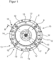
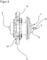
- the FIG. 1 shows a balancing device 1 for a fuselage group 2 of a turbocharger.
- the fuselage group 2 comprises a shaft 3, at the ends of which in each case a turbine wheel 4 or a compressor wheel 5 of the turbocharger are fastened and fixed via a shaft nut 3a.
- the balancing device 1 is provided with a base body 6, which has a centrally arranged receptacle 7 in order to insert the body group 2 into the receptacle 7 and to keep the rotation element 3, 4, 5 rotating about its axis of rotation via bearings which are not shown in detail.
- a plurality of hydraulic cylinders 8 arranged around the receptacle 7 are provided, by means of which the trunk group 2 is arranged in the central position Recording 7 is attached.
- the main body 6 has a circular decoupling plate 9, which comprises an inner plate section 10 and an outer plate section 11, which is elastically connected to the inner plate section 10 and surrounds the inner plate section 10, fixed in the balancing device 1.
- the decoupling plate 9 are along the circumference of the decoupling plate 9, d. H. along a circular arc about the central axis of rotation of the rotary member 3, 4, 5 arranged circumferential slots 12 are provided, via which the inner plate portion 10 is resiliently decoupled from the outer plate portion 11.
- the circumferential slots 12 are arranged so that they extend almost along the entire circumference of the decoupling plate 9.
- the individual circumferential slots 12 are spaced from each other in such a way that four, separate holding portions 13 in the decoupling plate 9 form.
- the circumferential slots 12 are each arranged over a length of 80 ° of the circumferential length of each holding section 13 of the decoupling plate 9.
- Recesses in the form of spring webs 14 and spring lugs 15 are provided in the decoupling plate 9 at the end regions of the circumferential slots 12, which are adapted to the expected load in the holding sections 13, ie in the region of expected bending and torsional forces as spring lugs 15, 10 Range of expected due to up and down movements caused linear forces as spring bars 14th
- the end portions of the circumferential slots 12 at the 12 o'clock position and at the 6 o'clock position are spring lugs 15 which are arranged to overlap one another at a distance from each other in the formation of the nose shape and capable of compressing vibrations due to rotations.
- the end regions of two adjacent peripheral slots 12 are designed as spring webs 14, which extend at a distance from one another parallel to the center axis of the decoupling plate 9.
- only three holding portions are provided on the decoupling plate 9, each extending over an angular range of 100 ° along the circumference of the base body 6.
- this embodiment will not be discussed further in this embodiment.
- the circumferential slots 12 and recesses 14, 15 have been introduced in the present embodiment by means of water jet cutting in the decoupling plate 9.
- the decoupling plate 9 is therefore further formed in one piece. Due to the various embodiments of the circumferential slots 12 and recesses 14, 15 and the webs 14a, 15a formed between them, a resilient mounting of the inner plate portion 10 from the stationary outer plate portion 11 while compensating for the effects of force due to the rotation and the mass movements achieved the various components. This is equivalent to a decoupling of the inner plate portion 10 from the stationary outer plate portion 11, which is accompanied by a significant reduction of the masses to be moved during the balancing process.
- pneumatic cylinder In order to fix the fuselage group 2 in the central receptacle 7 of the decoupling plate 9, first, attached to the outer plate portion 11, not shown pneumatic cylinder is extended. This method of the pneumatic cylinder causes a substantially powerless displacement of the arranged on the inner Plattenabschnit 10 hydraulic cylinder 8 within a provided in the inner plate portion 11 recess 16. By positioning the hydraulic cylinder adjoining the hydraulic cylinder 8 lever elements 17 can be tilted, resulting in a fixation of Allow body group 2 by means provided thereon retaining flanges 18.
Landscapes
- Engineering & Computer Science (AREA)
- Mechanical Engineering (AREA)
- General Engineering & Computer Science (AREA)
- Physics & Mathematics (AREA)
- General Physics & Mathematics (AREA)
- Life Sciences & Earth Sciences (AREA)
- Forests & Forestry (AREA)
- Supercharger (AREA)
- Testing Of Balance (AREA)
Priority Applications (8)
| Application Number | Priority Date | Filing Date | Title |
|---|---|---|---|
| EP17158764.5A EP3370052B1 (fr) | 2017-03-01 | 2017-03-01 | Dispositif d'équilibrage |
| PL17158764T PL3370052T3 (pl) | 2017-03-01 | 2017-03-01 | Wyważarka |
| HUE17158764A HUE055823T2 (hu) | 2017-03-01 | 2017-03-01 | Kiegyensúlyozó szerkezet |
| JP2018032657A JP6660967B2 (ja) | 2017-03-01 | 2018-02-27 | バランス装置 |
| KR1020180024232A KR102130523B1 (ko) | 2017-03-01 | 2018-02-28 | 균형 디바이스 |
| US15/907,909 US10408229B2 (en) | 2017-03-01 | 2018-02-28 | Balancing device |
| MX2018002622A MX2018002622A (es) | 2017-03-01 | 2018-03-01 | Dispositivo de equilibrio. |
| CN201810173098.9A CN108534951B (zh) | 2017-03-01 | 2018-03-01 | 平衡装置 |
Applications Claiming Priority (1)
| Application Number | Priority Date | Filing Date | Title |
|---|---|---|---|
| EP17158764.5A EP3370052B1 (fr) | 2017-03-01 | 2017-03-01 | Dispositif d'équilibrage |
Publications (2)
| Publication Number | Publication Date |
|---|---|
| EP3370052A1 true EP3370052A1 (fr) | 2018-09-05 |
| EP3370052B1 EP3370052B1 (fr) | 2021-05-12 |
Family
ID=58264388
Family Applications (1)
| Application Number | Title | Priority Date | Filing Date |
|---|---|---|---|
| EP17158764.5A Active EP3370052B1 (fr) | 2017-03-01 | 2017-03-01 | Dispositif d'équilibrage |
Country Status (8)
| Country | Link |
|---|---|
| US (1) | US10408229B2 (fr) |
| EP (1) | EP3370052B1 (fr) |
| JP (1) | JP6660967B2 (fr) |
| KR (1) | KR102130523B1 (fr) |
| CN (1) | CN108534951B (fr) |
| HU (1) | HUE055823T2 (fr) |
| MX (1) | MX2018002622A (fr) |
| PL (1) | PL3370052T3 (fr) |
Citations (3)
| Publication number | Priority date | Publication date | Assignee | Title |
|---|---|---|---|---|
| US4864859A (en) * | 1988-07-25 | 1989-09-12 | Allied-Signal Inc. | Method for dynamically balancing a mechanism having a high speed rotating component |
| DE102005053786A1 (de) * | 2005-11-09 | 2007-05-10 | Schenck Rotec Gmbh | Verfahren und Vorrichtung zum dynamischen Messen der Unwucht eines Rotors |
| US9261110B2 (en) | 2012-04-06 | 2016-02-16 | Carlo Buzzi | Balancing device, particularly for turbocompressors, and corresponding method |
Family Cites Families (8)
| Publication number | Priority date | Publication date | Assignee | Title |
|---|---|---|---|---|
| JP2733767B2 (ja) * | 1988-02-02 | 1998-03-30 | 本田技研工業株式会社 | ターボ回転機のバランス確認装置 |
| DE19627921A1 (de) * | 1996-07-11 | 1998-01-15 | Leybold Vakuum Gmbh | Verfahren zum Wuchten eines Rotors sowie für die Durchführung dieses Verfahrens geeigneter Rotor |
| DE102007032608B4 (de) * | 2007-07-11 | 2009-05-07 | Schenck Rotec Gmbh | Verfahren und Vorrichtung zum Zentrieren und Spannen eines Werkstücks in einer Auswuchtmaschine |
| DE102007058592A1 (de) * | 2007-12-04 | 2009-06-10 | Schenck Rotec Gmbh | Vorrichtung zum dynamischen Messen der Unwucht des Rotors eines Turboladers |
| DE102008049144A1 (de) * | 2008-09-26 | 2010-04-01 | Bosch Mahle Turbo Systems Gmbh & Co. Kg | Vorrichtung zum Auswuchten eines Rotors |
| FR2997138B1 (fr) * | 2012-10-18 | 2014-11-14 | Snecma | Dispositif et procede de commande du calage des pales |
| JP5974370B2 (ja) * | 2013-03-18 | 2016-08-23 | 株式会社Ihi | 回転機械支持装置 |
| JP6596749B2 (ja) * | 2015-10-28 | 2019-10-30 | 三菱日立パワーシステムズ株式会社 | 回転機械及び回転機械の制御方法 |
-
2017
- 2017-03-01 EP EP17158764.5A patent/EP3370052B1/fr active Active
- 2017-03-01 HU HUE17158764A patent/HUE055823T2/hu unknown
- 2017-03-01 PL PL17158764T patent/PL3370052T3/pl unknown
-
2018
- 2018-02-27 JP JP2018032657A patent/JP6660967B2/ja active Active
- 2018-02-28 KR KR1020180024232A patent/KR102130523B1/ko active Active
- 2018-02-28 US US15/907,909 patent/US10408229B2/en active Active
- 2018-03-01 CN CN201810173098.9A patent/CN108534951B/zh active Active
- 2018-03-01 MX MX2018002622A patent/MX2018002622A/es unknown
Patent Citations (3)
| Publication number | Priority date | Publication date | Assignee | Title |
|---|---|---|---|---|
| US4864859A (en) * | 1988-07-25 | 1989-09-12 | Allied-Signal Inc. | Method for dynamically balancing a mechanism having a high speed rotating component |
| DE102005053786A1 (de) * | 2005-11-09 | 2007-05-10 | Schenck Rotec Gmbh | Verfahren und Vorrichtung zum dynamischen Messen der Unwucht eines Rotors |
| US9261110B2 (en) | 2012-04-06 | 2016-02-16 | Carlo Buzzi | Balancing device, particularly for turbocompressors, and corresponding method |
Also Published As
| Publication number | Publication date |
|---|---|
| EP3370052B1 (fr) | 2021-05-12 |
| US20180252235A1 (en) | 2018-09-06 |
| US10408229B2 (en) | 2019-09-10 |
| JP6660967B2 (ja) | 2020-03-11 |
| CN108534951B (zh) | 2020-08-18 |
| KR102130523B1 (ko) | 2020-07-07 |
| CN108534951A (zh) | 2018-09-14 |
| PL3370052T3 (pl) | 2021-11-15 |
| HUE055823T2 (hu) | 2021-12-28 |
| JP2018163145A (ja) | 2018-10-18 |
| KR20180100492A (ko) | 2018-09-11 |
| MX2018002622A (es) | 2018-11-09 |
Similar Documents
| Publication | Publication Date | Title |
|---|---|---|
| EP0733816B1 (fr) | Articulation rotative | |
| EP2927661A2 (fr) | Actionneur | |
| EP1771713B1 (fr) | Anneau d'equilibrage et procede d'equilibrage d'une partie structurale rotative | |
| DE102012206755A1 (de) | Steuerstangenanordnung | |
| EP2428788B1 (fr) | Dispositif de palier de pivotement d'un rotor devant être équilibré | |
| EP4051918B1 (fr) | Banc d'essai | |
| WO2020234116A1 (fr) | Support de roue | |
| DE602005004737T2 (de) | Leitschaufelstufe eines Leitapparates die von einen drehbaren Ring angetrieben wird wobei der Ring von Elektromotoren versetzt wird | |
| WO1993020362A1 (fr) | Systeme de palier auxiliaire pour un rotor monte flottant sur un stator | |
| EP1952906B1 (fr) | Rotor d'une machine à dresser et machine à dresser | |
| EP3370052B1 (fr) | Dispositif d'équilibrage | |
| DE2934710C2 (de) | Rotor zur Drehenergiespeicherung | |
| EP2041452B1 (fr) | Dispositif d'équilibrage et procédé | |
| DE202017101161U1 (de) | Wuchteinrichtung | |
| DE4335785A1 (de) | Ruderstelleinrichtung | |
| DE202017007453U1 (de) | Wuchteinrichtung | |
| DE60215327T2 (de) | Turbinen- oder kompressorvorrichtung und verfahren zur montage der vorrichtung | |
| EP4045819B1 (fr) | Système d'entraînement | |
| EP0402607B1 (fr) | Dispositif d'ajustage d'un contre-poids et procédé de fixation d'un contre-poids ajusté à un vilbrequin au moyen du dispositif | |
| EP2397657B1 (fr) | Procédé pour le contrôle d'alignement d'un palier dans une turbine à gaz ou à vapeur et une telle turbine à gaz ou à vapeur | |
| EP2221596B1 (fr) | Dispositif d'équilibrage de corps tournants | |
| EP3375551B1 (fr) | Support de suspension à jeu radial réglable | |
| EP3976320B1 (fr) | Outil pour maintenir l'arbre haute pression d'un mécanisme de propulsion d'avion | |
| EP0013734B1 (fr) | Dispositif pour l'équilibrage dynamique de corps rotatifs, en particulier de meules | |
| DE102019208531A1 (de) | Kraftfahrzeugschwingungsdämpfer |
Legal Events
| Date | Code | Title | Description |
|---|---|---|---|
| REG | Reference to a national code |
Ref country code: DE Ref legal event code: R138 Ref document number: 202017007453 Country of ref document: DE Free format text: GERMAN DOCUMENT NUMBER IS 502017010316 |
|
| PUAI | Public reference made under article 153(3) epc to a published international application that has entered the european phase |
Free format text: ORIGINAL CODE: 0009012 |
|
| STAA | Information on the status of an ep patent application or granted ep patent |
Free format text: STATUS: THE APPLICATION HAS BEEN PUBLISHED |
|
| AK | Designated contracting states |
Kind code of ref document: A1 Designated state(s): AL AT BE BG CH CY CZ DE DK EE ES FI FR GB GR HR HU IE IS IT LI LT LU LV MC MK MT NL NO PL PT RO RS SE SI SK SM TR |
|
| AX | Request for extension of the european patent |
Extension state: BA ME |
|
| STAA | Information on the status of an ep patent application or granted ep patent |
Free format text: STATUS: REQUEST FOR EXAMINATION WAS MADE |
|
| 17P | Request for examination filed |
Effective date: 20181123 |
|
| RBV | Designated contracting states (corrected) |
Designated state(s): AL AT BE BG CH CY CZ DE DK EE ES FI FR GB GR HR HU IE IS IT LI LT LU LV MC MK MT NL NO PL PT RO RS SE SI SK SM TR |
|
| STAA | Information on the status of an ep patent application or granted ep patent |
Free format text: STATUS: EXAMINATION IS IN PROGRESS |
|
| 17Q | First examination report despatched |
Effective date: 20200603 |
|
| GRAP | Despatch of communication of intention to grant a patent |
Free format text: ORIGINAL CODE: EPIDOSNIGR1 |
|
| STAA | Information on the status of an ep patent application or granted ep patent |
Free format text: STATUS: GRANT OF PATENT IS INTENDED |
|
| RAP1 | Party data changed (applicant data changed or rights of an application transferred) |
Owner name: CHRISTOPH BOEHMER BETRIEBSVERPACHTUNG GMBH |
|
| RIC1 | Information provided on ipc code assigned before grant |
Ipc: F04D 25/02 20060101ALI20201203BHEP Ipc: F01D 25/28 20060101ALI20201203BHEP Ipc: G01M 1/04 20060101AFI20201203BHEP Ipc: F04D 29/66 20060101ALI20201203BHEP Ipc: F01D 5/02 20060101ALI20201203BHEP |
|
| INTG | Intention to grant announced |
Effective date: 20201221 |
|
| GRAS | Grant fee paid |
Free format text: ORIGINAL CODE: EPIDOSNIGR3 |
|
| GRAA | (expected) grant |
Free format text: ORIGINAL CODE: 0009210 |
|
| STAA | Information on the status of an ep patent application or granted ep patent |
Free format text: STATUS: THE PATENT HAS BEEN GRANTED |
|
| AK | Designated contracting states |
Kind code of ref document: B1 Designated state(s): AL AT BE BG CH CY CZ DE DK EE ES FI FR GB GR HR HU IE IS IT LI LT LU LV MC MK MT NL NO PL PT RO RS SE SI SK SM TR |
|
| REG | Reference to a national code |
Ref country code: GB Ref legal event code: FG4D Free format text: NOT ENGLISH |
|
| REG | Reference to a national code |
Ref country code: CH Ref legal event code: EP |
|
| REG | Reference to a national code |
Ref country code: DE Ref legal event code: R096 Ref document number: 502017010316 Country of ref document: DE |
|
| REG | Reference to a national code |
Ref country code: IE Ref legal event code: FG4D Free format text: LANGUAGE OF EP DOCUMENT: GERMAN |
|
| REG | Reference to a national code |
Ref country code: AT Ref legal event code: REF Ref document number: 1392496 Country of ref document: AT Kind code of ref document: T Effective date: 20210615 |
|
| REG | Reference to a national code |
Ref country code: LT Ref legal event code: MG9D |
|
| REG | Reference to a national code |
Ref country code: NL Ref legal event code: MP Effective date: 20210512 |
|
| PG25 | Lapsed in a contracting state [announced via postgrant information from national office to epo] |
Ref country code: HR Free format text: LAPSE BECAUSE OF FAILURE TO SUBMIT A TRANSLATION OF THE DESCRIPTION OR TO PAY THE FEE WITHIN THE PRESCRIBED TIME-LIMIT Effective date: 20210512 Ref country code: BG Free format text: LAPSE BECAUSE OF FAILURE TO SUBMIT A TRANSLATION OF THE DESCRIPTION OR TO PAY THE FEE WITHIN THE PRESCRIBED TIME-LIMIT Effective date: 20210812 Ref country code: FI Free format text: LAPSE BECAUSE OF FAILURE TO SUBMIT A TRANSLATION OF THE DESCRIPTION OR TO PAY THE FEE WITHIN THE PRESCRIBED TIME-LIMIT Effective date: 20210512 Ref country code: LT Free format text: LAPSE BECAUSE OF FAILURE TO SUBMIT A TRANSLATION OF THE DESCRIPTION OR TO PAY THE FEE WITHIN THE PRESCRIBED TIME-LIMIT Effective date: 20210512 |
|
| PG25 | Lapsed in a contracting state [announced via postgrant information from national office to epo] |
Ref country code: GR Free format text: LAPSE BECAUSE OF FAILURE TO SUBMIT A TRANSLATION OF THE DESCRIPTION OR TO PAY THE FEE WITHIN THE PRESCRIBED TIME-LIMIT Effective date: 20210813 Ref country code: IS Free format text: LAPSE BECAUSE OF FAILURE TO SUBMIT A TRANSLATION OF THE DESCRIPTION OR TO PAY THE FEE WITHIN THE PRESCRIBED TIME-LIMIT Effective date: 20210912 Ref country code: LV Free format text: LAPSE BECAUSE OF FAILURE TO SUBMIT A TRANSLATION OF THE DESCRIPTION OR TO PAY THE FEE WITHIN THE PRESCRIBED TIME-LIMIT Effective date: 20210512 Ref country code: SE Free format text: LAPSE BECAUSE OF FAILURE TO SUBMIT A TRANSLATION OF THE DESCRIPTION OR TO PAY THE FEE WITHIN THE PRESCRIBED TIME-LIMIT Effective date: 20210512 Ref country code: RS Free format text: LAPSE BECAUSE OF FAILURE TO SUBMIT A TRANSLATION OF THE DESCRIPTION OR TO PAY THE FEE WITHIN THE PRESCRIBED TIME-LIMIT Effective date: 20210512 Ref country code: NO Free format text: LAPSE BECAUSE OF FAILURE TO SUBMIT A TRANSLATION OF THE DESCRIPTION OR TO PAY THE FEE WITHIN THE PRESCRIBED TIME-LIMIT Effective date: 20210812 Ref country code: PT Free format text: LAPSE BECAUSE OF FAILURE TO SUBMIT A TRANSLATION OF THE DESCRIPTION OR TO PAY THE FEE WITHIN THE PRESCRIBED TIME-LIMIT Effective date: 20210913 |
|
| REG | Reference to a national code |
Ref country code: HU Ref legal event code: AG4A Ref document number: E055823 Country of ref document: HU |
|
| PG25 | Lapsed in a contracting state [announced via postgrant information from national office to epo] |
Ref country code: NL Free format text: LAPSE BECAUSE OF FAILURE TO SUBMIT A TRANSLATION OF THE DESCRIPTION OR TO PAY THE FEE WITHIN THE PRESCRIBED TIME-LIMIT Effective date: 20210512 |
|
| PG25 | Lapsed in a contracting state [announced via postgrant information from national office to epo] |
Ref country code: SM Free format text: LAPSE BECAUSE OF FAILURE TO SUBMIT A TRANSLATION OF THE DESCRIPTION OR TO PAY THE FEE WITHIN THE PRESCRIBED TIME-LIMIT Effective date: 20210512 Ref country code: SK Free format text: LAPSE BECAUSE OF FAILURE TO SUBMIT A TRANSLATION OF THE DESCRIPTION OR TO PAY THE FEE WITHIN THE PRESCRIBED TIME-LIMIT Effective date: 20210512 Ref country code: RO Free format text: LAPSE BECAUSE OF FAILURE TO SUBMIT A TRANSLATION OF THE DESCRIPTION OR TO PAY THE FEE WITHIN THE PRESCRIBED TIME-LIMIT Effective date: 20210512 Ref country code: ES Free format text: LAPSE BECAUSE OF FAILURE TO SUBMIT A TRANSLATION OF THE DESCRIPTION OR TO PAY THE FEE WITHIN THE PRESCRIBED TIME-LIMIT Effective date: 20210512 Ref country code: CZ Free format text: LAPSE BECAUSE OF FAILURE TO SUBMIT A TRANSLATION OF THE DESCRIPTION OR TO PAY THE FEE WITHIN THE PRESCRIBED TIME-LIMIT Effective date: 20210512 Ref country code: DK Free format text: LAPSE BECAUSE OF FAILURE TO SUBMIT A TRANSLATION OF THE DESCRIPTION OR TO PAY THE FEE WITHIN THE PRESCRIBED TIME-LIMIT Effective date: 20210512 Ref country code: EE Free format text: LAPSE BECAUSE OF FAILURE TO SUBMIT A TRANSLATION OF THE DESCRIPTION OR TO PAY THE FEE WITHIN THE PRESCRIBED TIME-LIMIT Effective date: 20210512 |
|
| REG | Reference to a national code |
Ref country code: DE Ref legal event code: R097 Ref document number: 502017010316 Country of ref document: DE |
|
| PLBE | No opposition filed within time limit |
Free format text: ORIGINAL CODE: 0009261 |
|
| STAA | Information on the status of an ep patent application or granted ep patent |
Free format text: STATUS: NO OPPOSITION FILED WITHIN TIME LIMIT |
|
| 26N | No opposition filed |
Effective date: 20220215 |
|
| PG25 | Lapsed in a contracting state [announced via postgrant information from national office to epo] |
Ref country code: IS Free format text: LAPSE BECAUSE OF FAILURE TO SUBMIT A TRANSLATION OF THE DESCRIPTION OR TO PAY THE FEE WITHIN THE PRESCRIBED TIME-LIMIT Effective date: 20210912 Ref country code: AL Free format text: LAPSE BECAUSE OF FAILURE TO SUBMIT A TRANSLATION OF THE DESCRIPTION OR TO PAY THE FEE WITHIN THE PRESCRIBED TIME-LIMIT Effective date: 20210512 |
|
| PG25 | Lapsed in a contracting state [announced via postgrant information from national office to epo] |
Ref country code: MC Free format text: LAPSE BECAUSE OF FAILURE TO SUBMIT A TRANSLATION OF THE DESCRIPTION OR TO PAY THE FEE WITHIN THE PRESCRIBED TIME-LIMIT Effective date: 20210512 |
|
| GBPC | Gb: european patent ceased through non-payment of renewal fee |
Effective date: 20220301 |
|
| REG | Reference to a national code |
Ref country code: BE Ref legal event code: MM Effective date: 20220331 |
|
| PG25 | Lapsed in a contracting state [announced via postgrant information from national office to epo] |
Ref country code: LU Free format text: LAPSE BECAUSE OF NON-PAYMENT OF DUE FEES Effective date: 20220301 Ref country code: IE Free format text: LAPSE BECAUSE OF NON-PAYMENT OF DUE FEES Effective date: 20220301 Ref country code: GB Free format text: LAPSE BECAUSE OF NON-PAYMENT OF DUE FEES Effective date: 20220301 |
|
| PG25 | Lapsed in a contracting state [announced via postgrant information from national office to epo] |
Ref country code: BE Free format text: LAPSE BECAUSE OF NON-PAYMENT OF DUE FEES Effective date: 20220331 |
|
| P01 | Opt-out of the competence of the unified patent court (upc) registered |
Effective date: 20230404 |
|
| P02 | Opt-out of the competence of the unified patent court (upc) changed |
Effective date: 20230525 |
|
| PG25 | Lapsed in a contracting state [announced via postgrant information from national office to epo] |
Ref country code: MK Free format text: LAPSE BECAUSE OF FAILURE TO SUBMIT A TRANSLATION OF THE DESCRIPTION OR TO PAY THE FEE WITHIN THE PRESCRIBED TIME-LIMIT Effective date: 20210512 Ref country code: CY Free format text: LAPSE BECAUSE OF FAILURE TO SUBMIT A TRANSLATION OF THE DESCRIPTION OR TO PAY THE FEE WITHIN THE PRESCRIBED TIME-LIMIT Effective date: 20210512 |
|
| PG25 | Lapsed in a contracting state [announced via postgrant information from national office to epo] |
Ref country code: TR Free format text: LAPSE BECAUSE OF FAILURE TO SUBMIT A TRANSLATION OF THE DESCRIPTION OR TO PAY THE FEE WITHIN THE PRESCRIBED TIME-LIMIT Effective date: 20210512 |
|
| PG25 | Lapsed in a contracting state [announced via postgrant information from national office to epo] |
Ref country code: MT Free format text: LAPSE BECAUSE OF FAILURE TO SUBMIT A TRANSLATION OF THE DESCRIPTION OR TO PAY THE FEE WITHIN THE PRESCRIBED TIME-LIMIT Effective date: 20210512 |
|
| PGFP | Annual fee paid to national office [announced via postgrant information from national office to epo] |
Ref country code: IT Payment date: 20250331 Year of fee payment: 9 |
|
| PGFP | Annual fee paid to national office [announced via postgrant information from national office to epo] |
Ref country code: CH Payment date: 20250401 Year of fee payment: 9 |
|
| REG | Reference to a national code |
Ref country code: CH Ref legal event code: U11 Free format text: ST27 STATUS EVENT CODE: U-0-0-U10-U11 (AS PROVIDED BY THE NATIONAL OFFICE) Effective date: 20260401 |
|
| PGFP | Annual fee paid to national office [announced via postgrant information from national office to epo] |
Ref country code: DE Payment date: 20260121 Year of fee payment: 10 |
|
| PGFP | Annual fee paid to national office [announced via postgrant information from national office to epo] |
Ref country code: AT Payment date: 20260304 Year of fee payment: 10 |
|
| PGFP | Annual fee paid to national office [announced via postgrant information from national office to epo] |
Ref country code: HU Payment date: 20260225 Year of fee payment: 10 |
|
| PGFP | Annual fee paid to national office [announced via postgrant information from national office to epo] |
Ref country code: FR Payment date: 20260209 Year of fee payment: 10 |
|
| PGFP | Annual fee paid to national office [announced via postgrant information from national office to epo] |
Ref country code: PL Payment date: 20260220 Year of fee payment: 10 |