EP3370325B1 - Rotor de type à aimant, machine électrique rotative à rotor de type à aimant, et automobile électrique à machine électrique rotative - Google Patents
Rotor de type à aimant, machine électrique rotative à rotor de type à aimant, et automobile électrique à machine électrique rotative Download PDFInfo
- Publication number
- EP3370325B1 EP3370325B1 EP16859512.2A EP16859512A EP3370325B1 EP 3370325 B1 EP3370325 B1 EP 3370325B1 EP 16859512 A EP16859512 A EP 16859512A EP 3370325 B1 EP3370325 B1 EP 3370325B1
- Authority
- EP
- European Patent Office
- Prior art keywords
- magnetic
- rotary electric
- electric machine
- magnet
- type rotor
- Prior art date
- Legal status (The legal status is an assumption and is not a legal conclusion. Google has not performed a legal analysis and makes no representation as to the accuracy of the status listed.)
- Active
Links
Images


Classifications
-
- H—ELECTRICITY
- H02—GENERATION; CONVERSION OR DISTRIBUTION OF ELECTRIC POWER
- H02K—DYNAMO-ELECTRIC MACHINES
- H02K1/00—Details of the magnetic circuit
- H02K1/06—Details of the magnetic circuit characterised by the shape, form or construction
- H02K1/22—Rotating parts of the magnetic circuit
- H02K1/27—Rotor cores with permanent magnets
- H02K1/2706—Inner rotors
- H02K1/272—Inner rotors the magnetisation axis of the magnets being perpendicular to the rotor axis
- H02K1/274—Inner rotors the magnetisation axis of the magnets being perpendicular to the rotor axis the rotor consisting of two or more circumferentially positioned magnets
- H02K1/2753—Inner rotors the magnetisation axis of the magnets being perpendicular to the rotor axis the rotor consisting of two or more circumferentially positioned magnets the rotor consisting of magnets or groups of magnets arranged with alternating polarity
- H02K1/276—Magnets embedded in the magnetic core, e.g. interior permanent magnets [IPM]
- H02K1/2766—Magnets embedded in the magnetic core, e.g. interior permanent magnets [IPM] having a flux concentration effect
-
- H—ELECTRICITY
- H02—GENERATION; CONVERSION OR DISTRIBUTION OF ELECTRIC POWER
- H02K—DYNAMO-ELECTRIC MACHINES
- H02K1/00—Details of the magnetic circuit
- H02K1/06—Details of the magnetic circuit characterised by the shape, form or construction
- H02K1/22—Rotating parts of the magnetic circuit
- H02K1/27—Rotor cores with permanent magnets
-
- H—ELECTRICITY
- H02—GENERATION; CONVERSION OR DISTRIBUTION OF ELECTRIC POWER
- H02K—DYNAMO-ELECTRIC MACHINES
- H02K2201/00—Specific aspects not provided for in the other groups of this subclass relating to the magnetic circuits
- H02K2201/06—Magnetic cores, or permanent magnets characterised by their skew
-
- H—ELECTRICITY
- H02—GENERATION; CONVERSION OR DISTRIBUTION OF ELECTRIC POWER
- H02K—DYNAMO-ELECTRIC MACHINES
- H02K29/00—Motors or generators having non-mechanical commutating devices, e.g. discharge tubes or semiconductor devices
- H02K29/03—Motors or generators having non-mechanical commutating devices, e.g. discharge tubes or semiconductor devices with a magnetic circuit specially adapted for avoiding torque ripples or self-starting problems
-
- Y—GENERAL TAGGING OF NEW TECHNOLOGICAL DEVELOPMENTS; GENERAL TAGGING OF CROSS-SECTIONAL TECHNOLOGIES SPANNING OVER SEVERAL SECTIONS OF THE IPC; TECHNICAL SUBJECTS COVERED BY FORMER USPC CROSS-REFERENCE ART COLLECTIONS [XRACs] AND DIGESTS
- Y02—TECHNOLOGIES OR APPLICATIONS FOR MITIGATION OR ADAPTATION AGAINST CLIMATE CHANGE
- Y02T—CLIMATE CHANGE MITIGATION TECHNOLOGIES RELATED TO TRANSPORTATION
- Y02T10/00—Road transport of goods or passengers
- Y02T10/60—Other road transportation technologies with climate change mitigation effect
- Y02T10/64—Electric machine technologies in electromobility
Definitions
- the present invention relates to a magnet-type rotor, a rotary electric machine equipped with the magnet-type rotor, and an electric vehicle equipped with the rotary electric machine.
- a large output power is required for a drive motor used in an electric vehicle and a hybrid vehicle (a drive rotary electric machine). Therefore, there is generally used a permanent magnet-type motor which uses a sintered magnet containing a rare earth element to hold a strong energy.
- a drive motor an embedded magnet motor which satisfies requirements such as a large torque at a low speed and a wide rotation speed range is used among the permanent magnet-type motors.
- torque ripples of the motor cause noises and vibrations.
- the torque ripples generated at a low speed in the electric vehicle causes uncomfortable to ride in.
- skewing is performed as a countermeasure in order to reduce the torque ripples.
- PTL 1 discloses a motor in which grooves are provided in a magnetic steel plate on the peripheral sides of the embedded magnet, and disposed to be deviated in an axial direction.
- the grooves are provided at places where the magnetic flux flows when powered up. Therefore, if the grooves are provided at positions where ripples are reduced when powered up, a cogging torque is increased. If the grooves are provided at positions where the cogging torque is reduced, the torque ripples are increased when powered up.
- An object of the present invention is to reduce the torque ripples which are generated when powered up and cause noises and vibrations of the motor.
- a rotary electric machine according to the embodiment can suppress torque ripples when powered up, and a compact size, a low cost, and low torque ripples can be realized. Therefore, for example, it is possible to provide an electric vehicle which is suitable as a drive motor of an electric vehicle, and has low vibrations and low noises, so that it is comfortable to ride in.
- the rotary electric machine according to the embodiment can be applied to a pure electric vehicle which is driven only by the rotary electric machine and a hybrid electric vehicle which is driven by both an engine and the rotary electric machine . The description hereinafter will be given about the hybrid electric vehicle as an example.
- an engine 120, a first rotary electric machine 200, a second rotary electric machine 201, and a high voltage battery 150 are mounted in a hybrid vehicle 100.
- the battery 150 is configured by a secondary battery such as a lithium ion battery or a nickel hydrogen battery, and outputs DC power of a high voltage from 250 to 600 or more.
- a secondary battery such as a lithium ion battery or a nickel hydrogen battery
- the battery 150 supplies the DC power to the rotary electric machines 200 and 201, and is supplied with the DC power from the rotary electric machines 200 and 201 during regenerative running.
- the transferring of the DC power between the battery 150 and the rotary electric machines 200 and 201 is performed through a power conversion device 160.
- a battery for supplying low-voltage power (for example, 14 voltage power) is mounted in the vehicle.
- a rotation torque generated by the engine 120 and the rotary electric machines 200 and 201 is transferred to front wheels 110 through a transmission 130 and a differential gear 140.
- FIG. 2 is a diagram schematically illustrating the entire configuration of the rotary electric machine 200.
- some part of the rotary electric machine 200 is illustrated in cross-sectional view, and thus the inside of the rotary electric machine 200 can be viewed.
- a stator 300 is supported in a housing 205.
- the stator 300 is provided with a stator core 305 and a stator winding 315.
- a rotor 400 is rotatably supported in the inner peripheral side of the stator core 305 with a gap 500 therebetween.
- the rotor 400 is provided with a rotor core 405 fixed to a shaft 450, a permanent magnet 415, and a non-magnetic end plate 440.
- the housing 205 includes a pair of end brackets 210 which are provided with gears 445 and 446.
- the shaft 450 is rotatably supported by these gears 445 and 446.
- the rotary electric machine 200 is a three-phase synchronous motor in which a permanent magnet is built.
- the rotary electric machine 200 operates as an electric machine which rotates the rotor 400 by supplying three-phase AC currents to the stator winding 315 wound around the stator core 305.
- the rotary electric machine 200 operates as a generator when being driven by the engine 120, and outputs the three-phase AC generated power.
- the rotary electric machine 200 has a function as an electric machine which generates a rotation torque on the basis of the electric energy and a function as a generator which generates power on the basis of the mechanic energy. These functions can be used selectively according to a running state of the vehicle.
- FIG. 3 is a diagram schematically illustrating the cross section of the stator 300 and the rotor 400 illustrated in FIG. 2 , that is, a cross-sectional view taken along line A-A of FIG. 2 . Further, the housing 205 and the shaft 450 are omitted in FIG. 3 .
- the stator core 305 is formed by stacking a plurality of magnetic materials (for example, a plurality of magnetic steel plates) in an axial direction, and is configured by a yoke portion and a teeth portion (also referred to as a projection or a salient pole) .
- the yoke portion is configured by a cylinder yoke core 306 (also referred to as a core back) which is fitted to the inner peripheral side of the housing 205.
- the teeth portion protrudes in a radial direction from the inner peripheral side of the yoke core 306, and is configured by a plurality of teeth cores 307 which are disposed in a peripheral direction at a predetermined interval therebetween.
- 24 teeth cores 307 are formed in the inner peripheral side of the yoke core 306.
- the slot 310 is provided with a slot insulator (not illustrated).
- a plurality of windings such as U-phase, V-phase, and W-phase are mounted to form the stator 300.
- a concentrated winding method is employed as a winding method of the stator winding 315 (see FIG. 2 ).
- the concentrated winding method is a winding method of directly winding the stator winding 315 about the teeth core 307 of one pole.
- the concentrated winding method is applied as a winding method, it is possible to reduce copper loss of the rotary electric machine 200, and also reduce a length in the axial direction of the stator 300.
- a magnetic insertion hole 410 to which a rectangular magnet is inserted is opened in the rotor core 405.
- the permanent magnet 415 is buried in the magnetic insertion hole 410, and fixed with an epoxy adhesive.
- a width in the peripheral direction of the magnetic insertion hole 410 is set to be larger than that in the peripheral direction of the permanent magnet 415.
- Magnetic cavities 416 are formed on both sides of the permanent magnet 415.
- the magnetic cavity 416 may be filled with an adhesive, or may be integrally fixed with the permanent magnet 415 with a molding resin.
- the permanent magnet 415 serves as a field pole of the rotor 400.
- a magnetization direction of the permanent magnet 415 is aligned in the radial direction.
- the magnetization direction is inversed at every field pole.
- a surface of a permanent magnet 415a on a side near the stator is an N pole and a surface on a side near the axis is an S pole
- a surface of a neighbor permanent magnet 415b on a side near the stator becomes the S pole
- a surface on a side near the axis becomes the N pole.
- the permanent magnets 415a and 415b are alternately disposed in the peripheral direction.
- 16 permanent magnets 415 are disposed at an equal interval.
- the rotor 400 is configured by 16 poles.
- the permanent magnet 415 may be buried in the rotor core 405 after magnetization, or may be magnetized by applying a strong magnetic field before the magnetization and after being inserted to the rotor core 405.
- the magnetized permanent magnet 415 is a strong magnet.
- dusts such as metal powder is attached to the permanent magnet 415 by the strong attraction force. Therefore, the magnetization after inserting the permanent magnet 415 to the rotor core 405 is better to improve a productivity of the rotary electric machine.
- a neodymium/samarium-based sintered magnet, a ferrate magnet, and a neodymium-based bond magnet may be used as the permanent magnet 415.
- a residual magnetic flux density of the permanent magnet 415 is about 0.4 to 1.3 T.
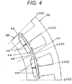
- FIG. 4 illustrates a part of the cross-sectional view of FIG. 3 on a magnified scale.
- an auxiliary salient pole 418 is formed between the respective permanent magnets 415 which form the magnetic pole.
- an axis in which the magnetic flux passes through the center of the magnet is called a d axis
- an axis in which the magnetic flux flows from gap to gap of the poles of the magnet is called a q axis.
- an iron core at the center between the poles of the magnet is called an auxiliary magnetic pole 418.
- a magnetic permeability of the permanent magnet 415 provided in the rotor 400 is almost the same as that of the air, a d-axis portion is magnetically concave, and a q-axis portion is magnetically convex when viewed from the stator 300. Therefore, the iron core of the q-axis portion is called a salient pole.
- a groove forming a magnetic cavity 417 is provided in the auxiliary magnetic pole 418 of the surface of the rotor 400 besides the magnetic cavities 416 formed on both sides of the permanent magnet 415.
- the magnetic cavity 416 is provided to reduce a cogging torque.
- the magnetic cavity 417 is provided to reduce the torque ripples when powered up, and formed along a concave shape of the outer surface of the rotor core 405.
- the magnetic cavities 417 may be formed symmetrically or asymmetrically to the q axis passing between the magnetic poles in the peripheral direction of the rotor 400, and are disposed symmetrically to the d axis which is the center axis of the magnetic pole. Further, the magnetic cavity 417 may be formed in a simple cavity region, and also may be formed by disposing a material having a magnetic resistance higher than that of the rotor core 405 in a cavity.
- FIG. 5 is a perspective view illustrating the rotor core 405 of the rotor 400 and the permanent magnet 415.
- the rotor core 405 is configured by a plurality of core pieces 406 as illustrated in FIG. 5 .
- a length of one core piece 406 in the axial direction is provided to be almost the same dimension as the length of another core piece 406 in the axial direction.
- a plurality of the core pieces 406 are stacked and connected as a unit while deviating by a predetermined angle in the peripheral direction of the axis of the rotor (referred to as "skew"). All the core pieces are integrally formed as one rotor 400. In this embodiment, five stages of the core pieces 406 are connected in the axial direction.
- the magnetic cavity 417 formed in the surface of the rotor 400 and the permanent magnet 415 buried in the magnetic insertion hole 410 are also disposed in the axial direction while deviating by a predetermined angle in the peripheral direction of the rotor.
- FIG. 6 is a diagram for describing a reluctance torque.
- the reluctance torque is generated by a difference in easiness that the magnetic flux passes between the d axis and the q axis illustrated in FIG. 6 (that is, a salient pole ratio indicating magnetic regularities).
- the rotating magnetic field is used for the permanent magnet 415 of the rotor 400 to generate a magnetic torque. Further, the reluctance torque operates on the rotor 400 in addition to the magnetic torque.
- the rotary electric machine to which the embodiment is applied is a rotary electric machine which uses both the magnetic torque and the reluctance torque of the auxiliary salient pole. Then, the torque ripples are generated from the magnetic torque and the reluctance torque.
- the torque ripples contain a ripple component generated when not powered up and a ripple component generated when powered up.
- the ripple component generated when not powered up is generally called a cogging torque. In a case where the rotary electric machine is actually used as a loaded state, the cogging torque and the ripple component when powered up are combined to generate the torque ripples.
- a skewing which is a method of reducing the torque ripples by changing and cancelling phases of the torque ripples is well known and thus will be omitted in explanation.
- a method of reducing the torque ripples using the magnetic cavity 417 provided in the auxiliary magnetic pole 418 of the rotor 400 will be described.
- the magnetic flux of the permanent magnet 415 is short-circuited in the ends of the magnet when not powered up. Therefore, no magnetic flux passes through the q axis.
- the magnetic flux passing the stator core 305 reaches the teeth core 307 through a core portion on a side near the stator of the permanent magnet 415. Therefore, since the magnetic cavity 417 does almost not influence on the magnetic flux which relates to the cogging torque when not powered up, it can be seen that the magnetic cavity 417 does not influence on the cogging torque.
- an induced voltage is a voltage to be generated when the magnetic flux of the magnet of the rotating rotor 400 is cancelled with the stator winding 315.
- the waveform of the induced voltage is not influenced by the presence/absence of the magnetic cavity 417 and by the shape.
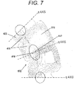
- FIG. 7 is a diagram illustrating a simulation result of a magnetic flux distribution in a case where the stator winding 315 in this embodiment is powered up.
- the magnetic flux flows to the q axis of the rotor core 405. This is because the current of the stator 300 generates the magnetic flux in the q axis.
- FIG. 8 is a partially enlarged view illustrating the auxiliary magnetic pole 418 and the magnetic cavity 417 in the simulation diagram of the magnetic flux distribution illustrated in FIG. 7 .
- the magnetic flux flowing to the auxiliary magnetic pole 418 of the q axis varies according to the magnetic cavity 417. In other words, it can be said that the magnetic flux (magnetic field) varies in a region of the magnetic cavity 417.
- the magnetic cavity 417 in this embodiment is desirably formed such that a center portion 419 in the peripheral direction of the magnetic varying region is overlapped with the q axis.
- FIG. 9 is a diagram illustrating a simulation result of the magnetic flux distribution in a case where the magnetic cavity 417 is not provided and the stator winding 315 is powered up. From the simulation results of FIGS. 7 and 9 , it can be seen that the flow of the magnetic flux of the auxiliary magnetic pole 418 varies according to the magnetic cavity 417. Therefore, it can be said that the magnetic cavity 417 in the auxiliary magnetic pole 418 is magnetically influenced only when powered up.
- FIG. 10 is a diagram illustrating waveforms of the torque ripples when powered up in four configurations: the rotor 400 (having skew, and the magnetic cavity 417); a rotor 400a (having no skew, no magnetic cavity 417); a rotor 400b (having skew, no magnetic cavity 417) ; and a rotor 400c (having no skew, having the magnetic cavity 417) in this embodiment.
- the rotor 400 having the skew and having the magnetic cavity 417 has the smallest amplitude of the waveforms of the torque ripples compared to the other configurations. Therefore, the torque ripples of the rotary electric machine 200 can be suppressed at a maximum by combining the skew of the rotor 400 and the magnetic cavity 417 in this embodiment.
- FIG. 11 is a diagram illustrating a result obtained by Fourier-expanding the waveforms of the torque ripples illustrated in FIG. 10 . From the result of FIG. 11 , it is possible to most reduce 6-th, 12-th, 18-th, 24-th, and 30-th harmonics using the rotor 400 having the skew and the magnetic cavity 417 compared to the other configurations.
- the configuration having the skew shows a high reduction effect in 12-th, 18-th, 24-th, and 30-th harmonics
- the magnetic cavity 417 of the auxiliary magnetic pole 418 shows a high reduction effect specially in 6-th harmonic. Therefore, regarding a reduction of the torque ripples in the case of the configuration having the skew and when the magnetic cavity 417 is loaded, it can be seen that different harmonics are reduced in the respective configurations. It also can be seen that the harmonic numbers reduced by the skew are high order compared to those reduced by the magnetic cavity 417.
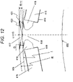
- FIG. 12 is an enlarged view of the auxiliary magnetic pole 418 and the magnetic cavities 416 and 417 of the cross-sectional view illustrated in FIG. 4 .
- the configurations are similar to those of the first embodiment except the following contents described below.
- the rotor core 405 illustrated in FIG. 12 is configured by a first side 420 which corresponds to one side of the magnetic cavity 417 formed about the q axis in the auxiliary magnetic pole 418 serving as an interpole section of the magnetic pole, and a second side 421 which corresponds to one side of the magnetic cavity 416 formed on both sides of the permanent magnet 415, and is disposed symmetrically to the d axis.
- a radius of the surface where the magnetic cavity 417 of the rotor core 405 is not formed is defined as R
- a distance from the center of the rotor to the bottom of the magnetic cavity 417 is defined as r
- a dimension where the first side 420 and the second side 421 are parallel is defined as D
- the dimension of D is desirably set to satisfy a relation of D ⁇ R - r.
- the permanent magnet 415 is fixed into the magnetic insertion hole 410 using an epoxy adhesive.
- the magnetic cavities 416 formed on both sides of the permanent magnet 415 may also be buried with an adhesive, or may be integrally fixed with the permanent magnet 415 using a shaping resin.
- the magnetic cavity 417 of this embodiment it is possible to avoid the magnetic cavities 416 and 417 of the adjacent core pieces 406 from being overlapped with each other when the permanent magnet 415 and the core piece 406 are skewed in the width direction of the rotor. Therefore, it is possible to prevent the adhesive filled in the magnetic insertion hole 410 from leaking out of the rotor core 405.
- FIG. 13 is a diagram illustrating a case where the stator winding 315 illustrated in FIG. 3 is formed in a distribution winding manner.
- the torque ripples in this embodiment vary depending on the shape of the rotor 400. Therefore, even in a case where the stator 300 is wound in a different manner such as a distribution winding manner, the reduction of the torque ripples can be achieved similarly to the above-described case.
- the other configurations are similar to those described in the first and second embodiments.
- the permanent magnet 415 buried in the magnetic insertion hole 410 of the rotor core 405 is disposed such that the surface of the magnet is perpendicular to the d axis.
- the magnetic insertion hole 410 and the permanent magnet 415 may be disposed, for example, a V shape about the d axis instead of being perpendicular to the d axis.
- the magnetic cavity 417 in the auxiliary magnetic pole 418 is formed about the q axis.
- the plurality of core pieces 406 are stacked and connected while deviating at a predetermined angle with respect to the peripheral direction of the axis of the rotor so as to provide a skew.
- the embodiments have been described about a motor for driving a vehicle.
- the present invention is not limited thereto, and can be applied to various types of motors.
- the present invention is not limited to the motors, and can be applied to various types of rotary electric machines such as a power generator (for example, alternator).
- a power generator for example, alternator
- the present invention is not limited to the above-described embodiments, the invention is defined by the scope of the appended claims.
Landscapes
- Engineering & Computer Science (AREA)
- Power Engineering (AREA)
- Permanent Field Magnets Of Synchronous Machinery (AREA)
- Iron Core Of Rotating Electric Machines (AREA)
Claims (6)
- Rotor du type à aimants, comprenant :une pluralité d'aimants permanents (415), etune pluralité de pièces de noyau (406) qui forment une pluralité de trous d'insertion magnétiques (410),dans lequel les aimants permanents (415) sont enfoncés dans les trous d'insertion magnétique (410),dans lequel la pluralité de pièces de noyau (406) sont empilées pour faire obliquer les aimants permanents (415),dans lequel la pluralité de pièces de noyau (406) forment une portion à résistance magnétique variable pour annuler un nombre d'harmoniques différentes un nombre d'harmoniques qui est annulé par l'obliquité, etdans lequel la portion à résistance magnétique variable est formée de telle sorte qu'une portion centrale dans une direction périphérique d'une région à magnétisme variable (419) générée par la portion à résistance magnétique variable est en chevauchement avec un axe q,dans lequel la portion à résistance magnétique variable est une cavité magnétique (416, 417),dans lequel la cavité magnétique (416,417) est une portion concave qui est formée dans une surface de la pièce de noyau,dans lequel la portion concave est formée symétriquement dans la direction périphérique sur un axe q,dans lequel un côté de la portion concave et un côté proche d'un pôle saillant auxiliaire du trou d'insertion magnétique (410) sont pratiquement parallèles,dans lequel une distance entre ledit un côté de la portion concave et ledit autre côté proche du pôle saillant auxiliaire est désigné comme étant D,dans lequel un rayon d'une surface où la portion concave de la pièce de noyau (406) n'est pas formée est désigné comme étant R,dans lequel une distance depuis un centre de rotation jusqu'à un fond de la portion concave est définie comme étant r, etdans lequel la pièce de noyau (406) est formée pour satisfaire D ≥ R -r.
- Rotor du type à aimants selon la revendication 1,
dans lequel le nombre d'harmoniques annulé par l'obliquité est une harmonique d'ordre supérieur comparé au nombre d'harmoniques annulé par la portion à résistance magnétique variable. - Rotor du type à aimants selon l'une quelconque des revendications 1 ou 2, dans lequel la pluralité de pièces de noyau (406) sont formées en empilant une pluralité de plaques d'acier dans une direction d'un axe de rotation.
- Machine électrique rotative, comprenant :le rotor du type à aimants selon l'une quelconque des revendications 1 à 3 ;etun stator (300) qui inclut un bobinage de stator (315), le bobinage de stator (315) étant enroulé selon une méthode de bobinage concentré.
- Machine électrique rotative, comprenant :le rotor du type à aimants selon l'une quelconque des revendications 1 à 3 ; etun stator (300) qui inclut un bobinage de stator (315), le bobinage de stator (315) étant enroulé selon une méthode de bobinage distribué
- Véhicule électrique qui utilise un couple de la machine électrique rotative (200, 201) équipée du rotor du type à aimants selon l'une quelconque des revendications 1 à 3 comme force d'entraînement.
Applications Claiming Priority (2)
| Application Number | Priority Date | Filing Date | Title |
|---|---|---|---|
| JP2015213642 | 2015-10-30 | ||
| PCT/JP2016/079563 WO2017073275A1 (fr) | 2015-10-30 | 2016-10-05 | Rotor de type à aimant, machine électrique rotative à rotor de type à aimant, et automobile électrique à machine électrique rotative |
Publications (3)
| Publication Number | Publication Date |
|---|---|
| EP3370325A1 EP3370325A1 (fr) | 2018-09-05 |
| EP3370325A4 EP3370325A4 (fr) | 2019-06-26 |
| EP3370325B1 true EP3370325B1 (fr) | 2022-08-10 |
Family
ID=58630024
Family Applications (1)
| Application Number | Title | Priority Date | Filing Date |
|---|---|---|---|
| EP16859512.2A Active EP3370325B1 (fr) | 2015-10-30 | 2016-10-05 | Rotor de type à aimant, machine électrique rotative à rotor de type à aimant, et automobile électrique à machine électrique rotative |
Country Status (5)
| Country | Link |
|---|---|
| US (1) | US10720807B2 (fr) |
| EP (1) | EP3370325B1 (fr) |
| JP (1) | JP6592525B2 (fr) |
| CN (1) | CN108141076B (fr) |
| WO (1) | WO2017073275A1 (fr) |
Families Citing this family (4)
| Publication number | Priority date | Publication date | Assignee | Title |
|---|---|---|---|---|
| JP6791909B2 (ja) * | 2018-07-06 | 2020-11-25 | ファナック株式会社 | 磁石が接着剤にて固定された磁石埋込み型電動機のロータおよび磁石埋込み型電動機のロータの製造方法 |
| CN110022013B (zh) * | 2019-05-29 | 2023-06-30 | 山东大学 | 一种磁极倾斜且凸极不对称的转子及高性能永磁电机 |
| JP7599357B2 (ja) * | 2021-03-16 | 2024-12-13 | 本田技研工業株式会社 | ステータ及び回転電機 |
| CN112886741B (zh) * | 2021-03-25 | 2022-01-28 | 珠海格力电器股份有限公司 | 转子结构、永磁同步电机及转子结构装配方法 |
Citations (2)
| Publication number | Priority date | Publication date | Assignee | Title |
|---|---|---|---|---|
| JP2008029095A (ja) * | 2006-07-20 | 2008-02-07 | Hitachi Industrial Equipment Systems Co Ltd | 永久磁石式回転電機及びそれを用いた圧縮機 |
| US20150069863A1 (en) * | 2013-09-06 | 2015-03-12 | General Electric Company | Interior permanent magnet machine having offset rotor sections |
Family Cites Families (27)
| Publication number | Priority date | Publication date | Assignee | Title |
|---|---|---|---|---|
| JP2978057B2 (ja) | 1994-06-07 | 1999-11-15 | 株式会社東芝 | 永久磁石形モータ及び冷却装置用コンプレッサ |
| US6956312B2 (en) * | 2001-02-14 | 2005-10-18 | Koyo Seiko Co., Ltd. | Brushless DC motor and method of manufacturing brushless DC motor |
| CN1278472C (zh) * | 2002-07-12 | 2006-10-04 | 株式会社日立产机系统 | 永磁式旋转电机及使用该电机的压缩机 |
| US7067948B2 (en) * | 2002-10-18 | 2006-06-27 | Mitsubishi Denki Kabushiki Kaisha | Permanent-magnet rotating machine |
| JP3885732B2 (ja) * | 2003-01-07 | 2007-02-28 | 日産自動車株式会社 | 永久磁石埋め込み同期モータ |
| JP4214998B2 (ja) * | 2003-04-11 | 2009-01-28 | 三菱電機株式会社 | 永久磁石式電動機 |
| JP4270942B2 (ja) * | 2003-05-29 | 2009-06-03 | 株式会社日立製作所 | 電動機 |
| JP4311182B2 (ja) | 2003-12-08 | 2009-08-12 | 日産自動車株式会社 | 回転電機の回転子 |
| JP4449035B2 (ja) * | 2004-03-10 | 2010-04-14 | 日立オートモティブシステムズ株式会社 | 電動車両用の永久磁石回転電機 |
| JP2008228390A (ja) * | 2007-03-09 | 2008-09-25 | Jtekt Corp | ブラシレスモータおよびそれを備えた電動パワーステアリング装置 |
| JP4708448B2 (ja) * | 2008-03-04 | 2011-06-22 | 日立オートモティブシステムズ株式会社 | 回転電機および電気自動車 |
| JP5123009B2 (ja) * | 2008-03-05 | 2013-01-16 | 株式会社ミツバ | ブラシレスモータ |
| JP2009219331A (ja) * | 2008-03-13 | 2009-09-24 | Hitachi Ltd | 永久磁石式ジェネレータとそれを用いたハイブリッド車両 |
| JP5433198B2 (ja) * | 2008-10-16 | 2014-03-05 | 日立オートモティブシステムズ株式会社 | 回転電機及び電気自動車 |
| EP2615721B1 (fr) * | 2010-09-06 | 2018-05-30 | Mitsubishi Electric Corporation | Machine électrique tournante du type à aimant permanent et dispositif de direction assistée utilisant cette machine |
| JP2013162557A (ja) * | 2012-02-01 | 2013-08-19 | Suzuki Motor Corp | 電動回転機 |
| JP5956277B2 (ja) * | 2012-08-07 | 2016-07-27 | 山洋電気株式会社 | 永久磁石式モータ、および永久磁石式モータの製造方法 |
| JP2014054060A (ja) | 2012-09-06 | 2014-03-20 | Mitsuba Corp | ブラシレスモータ |
| JP6128419B2 (ja) | 2013-01-15 | 2017-05-17 | 日本電産株式会社 | 回転電機 |
| KR101497502B1 (ko) * | 2013-02-19 | 2015-03-03 | (주) 코모텍 | 전동기 및 전동기 제조방법 |
| US9634530B2 (en) * | 2013-03-15 | 2017-04-25 | Steering Solutions Ip Holding Corporation | Interior permanent magnet motor with shifted rotor laminations |
| US9985507B2 (en) * | 2013-04-22 | 2018-05-29 | Mitsubishi Electric Corporation | Permanent magnet type motor |
| US9287742B2 (en) * | 2013-08-05 | 2016-03-15 | General Electric Company | Spoke permanent magnet machine with reduced torque ripple and method of manufacturing thereof |
| WO2015104956A1 (fr) * | 2014-01-08 | 2015-07-16 | 三菱電機株式会社 | Machine électrique rotative |
| JP2015208053A (ja) * | 2014-04-17 | 2015-11-19 | 日立アプライアンス株式会社 | 永久磁石式回転電機及びそれを用いた圧縮機 |
| US9985484B2 (en) * | 2015-06-09 | 2018-05-29 | Ford Global Technologies, Llc | Surface groove patterns for permanent magnet machine rotors |
| KR20180105901A (ko) * | 2017-03-16 | 2018-10-01 | 엘지전자 주식회사 | 영구 자석 매립형 회전자, 영구 자석형 모터 및 압축기 |
-
2016
- 2016-10-05 WO PCT/JP2016/079563 patent/WO2017073275A1/fr not_active Ceased
- 2016-10-05 CN CN201680055981.7A patent/CN108141076B/zh active Active
- 2016-10-05 EP EP16859512.2A patent/EP3370325B1/fr active Active
- 2016-10-05 US US15/771,063 patent/US10720807B2/en active Active
- 2016-10-05 JP JP2017547701A patent/JP6592525B2/ja active Active
Patent Citations (2)
| Publication number | Priority date | Publication date | Assignee | Title |
|---|---|---|---|---|
| JP2008029095A (ja) * | 2006-07-20 | 2008-02-07 | Hitachi Industrial Equipment Systems Co Ltd | 永久磁石式回転電機及びそれを用いた圧縮機 |
| US20150069863A1 (en) * | 2013-09-06 | 2015-03-12 | General Electric Company | Interior permanent magnet machine having offset rotor sections |
Also Published As
| Publication number | Publication date |
|---|---|
| CN108141076A (zh) | 2018-06-08 |
| EP3370325A4 (fr) | 2019-06-26 |
| EP3370325A1 (fr) | 2018-09-05 |
| US20180309334A1 (en) | 2018-10-25 |
| JPWO2017073275A1 (ja) | 2018-06-21 |
| US10720807B2 (en) | 2020-07-21 |
| CN108141076B (zh) | 2020-02-21 |
| JP6592525B2 (ja) | 2019-10-16 |
| WO2017073275A1 (fr) | 2017-05-04 |
Similar Documents
| Publication | Publication Date | Title |
|---|---|---|
| JP5948127B2 (ja) | 永久磁石回転電機及びそれを用いた電動車両 | |
| US9252634B2 (en) | Synchronous motor | |
| CN103872869B (zh) | 多间隙式旋转电机 | |
| CN101114777B (zh) | 爪齿型旋转电机 | |
| EP3514921B1 (fr) | Machine dynamo-électrique | |
| JPWO2012014260A1 (ja) | 回転電機及びそれを用いた電動車両 | |
| JP2009219331A (ja) | 永久磁石式ジェネレータとそれを用いたハイブリッド車両 | |
| EP3136559A1 (fr) | Moteur synchrone à aimant permanent et son rotor | |
| WO2011019069A1 (fr) | Machine dynamoélectrique pour utilisation dans des véhicules | |
| KR20220044429A (ko) | 서로 다른 회전자 세그먼트들을 적층한 전기 모터 및 그 설계 방법 | |
| EP3370325B1 (fr) | Rotor de type à aimant, machine électrique rotative à rotor de type à aimant, et automobile électrique à machine électrique rotative | |
| US20210006112A1 (en) | Rotary electric machine | |
| US20150091403A1 (en) | Transverse flux machine and vehicle | |
| JP5450472B2 (ja) | 永久磁石式ジェネレータとそれを用いたハイブリッド車両 | |
| US11837919B2 (en) | Rotary electric machine | |
| KR20170057386A (ko) | 릴럭턴스 보조 외부 로터 pmsm | |
| US7482724B2 (en) | Ipm electric rotating machine | |
| CN118432326A (zh) | 旋转电机的转子结构 | |
| JP6984164B2 (ja) | 回転電機 | |
| CN118432325A (zh) | 旋转电机的转子结构 | |
| JP2023016946A (ja) | 回転電機、回転電動機駆動システム、並びに電動車両 | |
| JP2011083114A (ja) | 電動機 | |
| JP6984165B2 (ja) | 回転電機 | |
| HK1243239A1 (en) | Reluctance assisted external rotor pmsm |
Legal Events
| Date | Code | Title | Description |
|---|---|---|---|
| STAA | Information on the status of an ep patent application or granted ep patent |
Free format text: STATUS: THE INTERNATIONAL PUBLICATION HAS BEEN MADE |
|
| PUAI | Public reference made under article 153(3) epc to a published international application that has entered the european phase |
Free format text: ORIGINAL CODE: 0009012 |
|
| STAA | Information on the status of an ep patent application or granted ep patent |
Free format text: STATUS: REQUEST FOR EXAMINATION WAS MADE |
|
| 17P | Request for examination filed |
Effective date: 20180530 |
|
| AK | Designated contracting states |
Kind code of ref document: A1 Designated state(s): AL AT BE BG CH CY CZ DE DK EE ES FI FR GB GR HR HU IE IS IT LI LT LU LV MC MK MT NL NO PL PT RO RS SE SI SK SM TR |
|
| AX | Request for extension of the european patent |
Extension state: BA ME |
|
| DAV | Request for validation of the european patent (deleted) | ||
| DAX | Request for extension of the european patent (deleted) | ||
| A4 | Supplementary search report drawn up and despatched |
Effective date: 20190523 |
|
| RIC1 | Information provided on ipc code assigned before grant |
Ipc: H02K 1/27 20060101AFI20190517BHEP |
|
| STAA | Information on the status of an ep patent application or granted ep patent |
Free format text: STATUS: EXAMINATION IS IN PROGRESS |
|
| 17Q | First examination report despatched |
Effective date: 20201215 |
|
| RAP3 | Party data changed (applicant data changed or rights of an application transferred) |
Owner name: HITACHI ASTEMO, LTD. |
|
| GRAP | Despatch of communication of intention to grant a patent |
Free format text: ORIGINAL CODE: EPIDOSNIGR1 |
|
| STAA | Information on the status of an ep patent application or granted ep patent |
Free format text: STATUS: GRANT OF PATENT IS INTENDED |
|
| INTG | Intention to grant announced |
Effective date: 20220323 |
|
| GRAS | Grant fee paid |
Free format text: ORIGINAL CODE: EPIDOSNIGR3 |
|
| GRAA | (expected) grant |
Free format text: ORIGINAL CODE: 0009210 |
|
| STAA | Information on the status of an ep patent application or granted ep patent |
Free format text: STATUS: THE PATENT HAS BEEN GRANTED |
|
| RIN1 | Information on inventor provided before grant (corrected) |
Inventor name: ZULAIKA MOHDBASIR Inventor name: FUKUDA TOMOHIRO Inventor name: YAMAZAKI SHINJI Inventor name: OKAMOTO HIROMITSU |
|
| AK | Designated contracting states |
Kind code of ref document: B1 Designated state(s): AL AT BE BG CH CY CZ DE DK EE ES FI FR GB GR HR HU IE IS IT LI LT LU LV MC MK MT NL NO PL PT RO RS SE SI SK SM TR |
|
| REG | Reference to a national code |
Ref country code: AT Ref legal event code: REF Ref document number: 1511286 Country of ref document: AT Kind code of ref document: T Effective date: 20220815 Ref country code: CH Ref legal event code: EP |
|
| REG | Reference to a national code |
Ref country code: IE Ref legal event code: FG4D |
|
| REG | Reference to a national code |
Ref country code: DE Ref legal event code: R096 Ref document number: 602016074238 Country of ref document: DE |
|
| REG | Reference to a national code |
Ref country code: NL Ref legal event code: MP Effective date: 20220810 |
|
| REG | Reference to a national code |
Ref country code: LT Ref legal event code: MG9D |
|
| PG25 | Lapsed in a contracting state [announced via postgrant information from national office to epo] |
Ref country code: SE Free format text: LAPSE BECAUSE OF FAILURE TO SUBMIT A TRANSLATION OF THE DESCRIPTION OR TO PAY THE FEE WITHIN THE PRESCRIBED TIME-LIMIT Effective date: 20220810 Ref country code: RS Free format text: LAPSE BECAUSE OF FAILURE TO SUBMIT A TRANSLATION OF THE DESCRIPTION OR TO PAY THE FEE WITHIN THE PRESCRIBED TIME-LIMIT Effective date: 20220810 Ref country code: PT Free format text: LAPSE BECAUSE OF FAILURE TO SUBMIT A TRANSLATION OF THE DESCRIPTION OR TO PAY THE FEE WITHIN THE PRESCRIBED TIME-LIMIT Effective date: 20221212 Ref country code: NO Free format text: LAPSE BECAUSE OF FAILURE TO SUBMIT A TRANSLATION OF THE DESCRIPTION OR TO PAY THE FEE WITHIN THE PRESCRIBED TIME-LIMIT Effective date: 20221110 Ref country code: NL Free format text: LAPSE BECAUSE OF FAILURE TO SUBMIT A TRANSLATION OF THE DESCRIPTION OR TO PAY THE FEE WITHIN THE PRESCRIBED TIME-LIMIT Effective date: 20220810 Ref country code: LV Free format text: LAPSE BECAUSE OF FAILURE TO SUBMIT A TRANSLATION OF THE DESCRIPTION OR TO PAY THE FEE WITHIN THE PRESCRIBED TIME-LIMIT Effective date: 20220810 Ref country code: LT Free format text: LAPSE BECAUSE OF FAILURE TO SUBMIT A TRANSLATION OF THE DESCRIPTION OR TO PAY THE FEE WITHIN THE PRESCRIBED TIME-LIMIT Effective date: 20220810 Ref country code: FI Free format text: LAPSE BECAUSE OF FAILURE TO SUBMIT A TRANSLATION OF THE DESCRIPTION OR TO PAY THE FEE WITHIN THE PRESCRIBED TIME-LIMIT Effective date: 20220810 |
|
| REG | Reference to a national code |
Ref country code: AT Ref legal event code: MK05 Ref document number: 1511286 Country of ref document: AT Kind code of ref document: T Effective date: 20220810 |
|
| PG25 | Lapsed in a contracting state [announced via postgrant information from national office to epo] |
Ref country code: PL Free format text: LAPSE BECAUSE OF FAILURE TO SUBMIT A TRANSLATION OF THE DESCRIPTION OR TO PAY THE FEE WITHIN THE PRESCRIBED TIME-LIMIT Effective date: 20220810 Ref country code: IS Free format text: LAPSE BECAUSE OF FAILURE TO SUBMIT A TRANSLATION OF THE DESCRIPTION OR TO PAY THE FEE WITHIN THE PRESCRIBED TIME-LIMIT Effective date: 20221210 Ref country code: HR Free format text: LAPSE BECAUSE OF FAILURE TO SUBMIT A TRANSLATION OF THE DESCRIPTION OR TO PAY THE FEE WITHIN THE PRESCRIBED TIME-LIMIT Effective date: 20220810 Ref country code: GR Free format text: LAPSE BECAUSE OF FAILURE TO SUBMIT A TRANSLATION OF THE DESCRIPTION OR TO PAY THE FEE WITHIN THE PRESCRIBED TIME-LIMIT Effective date: 20221111 |
|
| PG25 | Lapsed in a contracting state [announced via postgrant information from national office to epo] |
Ref country code: SM Free format text: LAPSE BECAUSE OF FAILURE TO SUBMIT A TRANSLATION OF THE DESCRIPTION OR TO PAY THE FEE WITHIN THE PRESCRIBED TIME-LIMIT Effective date: 20220810 Ref country code: RO Free format text: LAPSE BECAUSE OF FAILURE TO SUBMIT A TRANSLATION OF THE DESCRIPTION OR TO PAY THE FEE WITHIN THE PRESCRIBED TIME-LIMIT Effective date: 20220810 Ref country code: ES Free format text: LAPSE BECAUSE OF FAILURE TO SUBMIT A TRANSLATION OF THE DESCRIPTION OR TO PAY THE FEE WITHIN THE PRESCRIBED TIME-LIMIT Effective date: 20220810 Ref country code: DK Free format text: LAPSE BECAUSE OF FAILURE TO SUBMIT A TRANSLATION OF THE DESCRIPTION OR TO PAY THE FEE WITHIN THE PRESCRIBED TIME-LIMIT Effective date: 20220810 Ref country code: CZ Free format text: LAPSE BECAUSE OF FAILURE TO SUBMIT A TRANSLATION OF THE DESCRIPTION OR TO PAY THE FEE WITHIN THE PRESCRIBED TIME-LIMIT Effective date: 20220810 Ref country code: AT Free format text: LAPSE BECAUSE OF FAILURE TO SUBMIT A TRANSLATION OF THE DESCRIPTION OR TO PAY THE FEE WITHIN THE PRESCRIBED TIME-LIMIT Effective date: 20220810 |
|
| REG | Reference to a national code |
Ref country code: DE Ref legal event code: R097 Ref document number: 602016074238 Country of ref document: DE |
|
| PG25 | Lapsed in a contracting state [announced via postgrant information from national office to epo] |
Ref country code: SK Free format text: LAPSE BECAUSE OF FAILURE TO SUBMIT A TRANSLATION OF THE DESCRIPTION OR TO PAY THE FEE WITHIN THE PRESCRIBED TIME-LIMIT Effective date: 20220810 Ref country code: MC Free format text: LAPSE BECAUSE OF FAILURE TO SUBMIT A TRANSLATION OF THE DESCRIPTION OR TO PAY THE FEE WITHIN THE PRESCRIBED TIME-LIMIT Effective date: 20220810 Ref country code: EE Free format text: LAPSE BECAUSE OF FAILURE TO SUBMIT A TRANSLATION OF THE DESCRIPTION OR TO PAY THE FEE WITHIN THE PRESCRIBED TIME-LIMIT Effective date: 20220810 |
|
| REG | Reference to a national code |
Ref country code: CH Ref legal event code: PL |
|
| PLBE | No opposition filed within time limit |
Free format text: ORIGINAL CODE: 0009261 |
|
| STAA | Information on the status of an ep patent application or granted ep patent |
Free format text: STATUS: NO OPPOSITION FILED WITHIN TIME LIMIT |
|
| REG | Reference to a national code |
Ref country code: BE Ref legal event code: MM Effective date: 20221031 |
|
| PG25 | Lapsed in a contracting state [announced via postgrant information from national office to epo] |
Ref country code: LU Free format text: LAPSE BECAUSE OF NON-PAYMENT OF DUE FEES Effective date: 20221005 Ref country code: AL Free format text: LAPSE BECAUSE OF FAILURE TO SUBMIT A TRANSLATION OF THE DESCRIPTION OR TO PAY THE FEE WITHIN THE PRESCRIBED TIME-LIMIT Effective date: 20220810 |
|
| 26N | No opposition filed |
Effective date: 20230511 |
|
| GBPC | Gb: european patent ceased through non-payment of renewal fee |
Effective date: 20221110 |
|
| PG25 | Lapsed in a contracting state [announced via postgrant information from national office to epo] |
Ref country code: LI Free format text: LAPSE BECAUSE OF NON-PAYMENT OF DUE FEES Effective date: 20221031 Ref country code: FR Free format text: LAPSE BECAUSE OF NON-PAYMENT OF DUE FEES Effective date: 20221010 Ref country code: CH Free format text: LAPSE BECAUSE OF NON-PAYMENT OF DUE FEES Effective date: 20221031 |
|
| PG25 | Lapsed in a contracting state [announced via postgrant information from national office to epo] |
Ref country code: SI Free format text: LAPSE BECAUSE OF FAILURE TO SUBMIT A TRANSLATION OF THE DESCRIPTION OR TO PAY THE FEE WITHIN THE PRESCRIBED TIME-LIMIT Effective date: 20220810 |
|
| PG25 | Lapsed in a contracting state [announced via postgrant information from national office to epo] |
Ref country code: BE Free format text: LAPSE BECAUSE OF NON-PAYMENT OF DUE FEES Effective date: 20221031 |
|
| PG25 | Lapsed in a contracting state [announced via postgrant information from national office to epo] |
Ref country code: GB Free format text: LAPSE BECAUSE OF NON-PAYMENT OF DUE FEES Effective date: 20221110 Ref country code: IE Free format text: LAPSE BECAUSE OF NON-PAYMENT OF DUE FEES Effective date: 20221005 |
|
| PG25 | Lapsed in a contracting state [announced via postgrant information from national office to epo] |
Ref country code: HU Free format text: LAPSE BECAUSE OF FAILURE TO SUBMIT A TRANSLATION OF THE DESCRIPTION OR TO PAY THE FEE WITHIN THE PRESCRIBED TIME-LIMIT; INVALID AB INITIO Effective date: 20161005 |
|
| PG25 | Lapsed in a contracting state [announced via postgrant information from national office to epo] |
Ref country code: CY Free format text: LAPSE BECAUSE OF FAILURE TO SUBMIT A TRANSLATION OF THE DESCRIPTION OR TO PAY THE FEE WITHIN THE PRESCRIBED TIME-LIMIT Effective date: 20220810 |
|
| PG25 | Lapsed in a contracting state [announced via postgrant information from national office to epo] |
Ref country code: MK Free format text: LAPSE BECAUSE OF FAILURE TO SUBMIT A TRANSLATION OF THE DESCRIPTION OR TO PAY THE FEE WITHIN THE PRESCRIBED TIME-LIMIT Effective date: 20220810 Ref country code: IT Free format text: LAPSE BECAUSE OF FAILURE TO SUBMIT A TRANSLATION OF THE DESCRIPTION OR TO PAY THE FEE WITHIN THE PRESCRIBED TIME-LIMIT Effective date: 20220810 |
|
| PG25 | Lapsed in a contracting state [announced via postgrant information from national office to epo] |
Ref country code: TR Free format text: LAPSE BECAUSE OF FAILURE TO SUBMIT A TRANSLATION OF THE DESCRIPTION OR TO PAY THE FEE WITHIN THE PRESCRIBED TIME-LIMIT Effective date: 20220810 |
|
| PG25 | Lapsed in a contracting state [announced via postgrant information from national office to epo] |
Ref country code: BG Free format text: LAPSE BECAUSE OF FAILURE TO SUBMIT A TRANSLATION OF THE DESCRIPTION OR TO PAY THE FEE WITHIN THE PRESCRIBED TIME-LIMIT Effective date: 20220810 |
|
| PG25 | Lapsed in a contracting state [announced via postgrant information from national office to epo] |
Ref country code: MT Free format text: LAPSE BECAUSE OF FAILURE TO SUBMIT A TRANSLATION OF THE DESCRIPTION OR TO PAY THE FEE WITHIN THE PRESCRIBED TIME-LIMIT Effective date: 20220810 |
|
| PGFP | Annual fee paid to national office [announced via postgrant information from national office to epo] |
Ref country code: DE Payment date: 20250902 Year of fee payment: 10 |