EP3370885B1 - Verfahren und vorrichtung zur kontrolle eines sprühstrahls - Google Patents
Verfahren und vorrichtung zur kontrolle eines sprühstrahls Download PDFInfo
- Publication number
- EP3370885B1 EP3370885B1 EP16812885.8A EP16812885A EP3370885B1 EP 3370885 B1 EP3370885 B1 EP 3370885B1 EP 16812885 A EP16812885 A EP 16812885A EP 3370885 B1 EP3370885 B1 EP 3370885B1
- Authority
- EP
- European Patent Office
- Prior art keywords
- fluid pattern
- fluid
- pattern
- actual fluid
- actual
- Prior art date
- Legal status (The legal status is an assumption and is not a legal conclusion. Google has not performed a legal analysis and makes no representation as to the accuracy of the status listed.)
- Not-in-force
Links
- 239000012530 fluid Substances 0.000 title claims description 512
- 238000000034 method Methods 0.000 title claims description 28
- 239000007921 spray Substances 0.000 claims description 38
- 230000010287 polarization Effects 0.000 claims description 15
- 239000000758 substrate Substances 0.000 description 15
- 238000000576 coating method Methods 0.000 description 8
- 238000005286 illumination Methods 0.000 description 7
- 230000008569 process Effects 0.000 description 7
- 239000011248 coating agent Substances 0.000 description 6
- 238000010586 diagram Methods 0.000 description 4
- 238000001228 spectrum Methods 0.000 description 4
- 239000011324 bead Substances 0.000 description 2
- 230000006870 function Effects 0.000 description 2
- 239000000463 material Substances 0.000 description 2
- 238000012986 modification Methods 0.000 description 2
- 230000004048 modification Effects 0.000 description 2
- 230000010363 phase shift Effects 0.000 description 2
- 239000004065 semiconductor Substances 0.000 description 2
- 230000001360 synchronised effect Effects 0.000 description 2
- 239000000853 adhesive Substances 0.000 description 1
- 230000001070 adhesive effect Effects 0.000 description 1
- XAGFODPZIPBFFR-UHFFFAOYSA-N aluminium Chemical compound [Al] XAGFODPZIPBFFR-UHFFFAOYSA-N 0.000 description 1
- 229910052782 aluminium Inorganic materials 0.000 description 1
- 239000004411 aluminium Substances 0.000 description 1
- 238000000889 atomisation Methods 0.000 description 1
- 230000008901 benefit Effects 0.000 description 1
- 230000005540 biological transmission Effects 0.000 description 1
- 230000008859 change Effects 0.000 description 1
- 230000000295 complement effect Effects 0.000 description 1
- 230000005670 electromagnetic radiation Effects 0.000 description 1
- 238000005265 energy consumption Methods 0.000 description 1
- 238000001914 filtration Methods 0.000 description 1
- 239000002223 garnet Substances 0.000 description 1
- 238000003384 imaging method Methods 0.000 description 1
- 230000003287 optical effect Effects 0.000 description 1
- 239000003973 paint Substances 0.000 description 1
- 239000000565 sealant Substances 0.000 description 1
- 230000002123 temporal effect Effects 0.000 description 1
- 229910052727 yttrium Inorganic materials 0.000 description 1
- VWQVUPCCIRVNHF-UHFFFAOYSA-N yttrium atom Chemical compound [Y] VWQVUPCCIRVNHF-UHFFFAOYSA-N 0.000 description 1
Images




Classifications
-
- B—PERFORMING OPERATIONS; TRANSPORTING
- B05—SPRAYING OR ATOMISING IN GENERAL; APPLYING FLUENT MATERIALS TO SURFACES, IN GENERAL
- B05B—SPRAYING APPARATUS; ATOMISING APPARATUS; NOZZLES
- B05B12/00—Arrangements for controlling delivery; Arrangements for controlling the spray area
- B05B12/08—Arrangements for controlling delivery; Arrangements for controlling the spray area responsive to condition of liquid or other fluent material to be discharged, of ambient medium or of target ; responsive to condition of spray devices or of supply means, e.g. pipes, pumps or their drive means
- B05B12/082—Arrangements for controlling delivery; Arrangements for controlling the spray area responsive to condition of liquid or other fluent material to be discharged, of ambient medium or of target ; responsive to condition of spray devices or of supply means, e.g. pipes, pumps or their drive means responsive to a condition of the discharged jet or spray, e.g. to jet shape, spray pattern or droplet size
-
- B—PERFORMING OPERATIONS; TRANSPORTING
- B05—SPRAYING OR ATOMISING IN GENERAL; APPLYING FLUENT MATERIALS TO SURFACES, IN GENERAL
- B05B—SPRAYING APPARATUS; ATOMISING APPARATUS; NOZZLES
- B05B12/00—Arrangements for controlling delivery; Arrangements for controlling the spray area
- B05B12/08—Arrangements for controlling delivery; Arrangements for controlling the spray area responsive to condition of liquid or other fluent material to be discharged, of ambient medium or of target ; responsive to condition of spray devices or of supply means, e.g. pipes, pumps or their drive means
- B05B12/084—Arrangements for controlling delivery; Arrangements for controlling the spray area responsive to condition of liquid or other fluent material to be discharged, of ambient medium or of target ; responsive to condition of spray devices or of supply means, e.g. pipes, pumps or their drive means responsive to condition of liquid or other fluent material already sprayed on the target, e.g. coating thickness, weight or pattern
-
- B—PERFORMING OPERATIONS; TRANSPORTING
- B41—PRINTING; LINING MACHINES; TYPEWRITERS; STAMPS
- B41J—TYPEWRITERS; SELECTIVE PRINTING MECHANISMS, i.e. MECHANISMS PRINTING OTHERWISE THAN FROM A FORME; CORRECTION OF TYPOGRAPHICAL ERRORS
- B41J3/00—Typewriters or selective printing or marking mechanisms characterised by the purpose for which they are constructed
- B41J3/28—Typewriters or selective printing or marking mechanisms characterised by the purpose for which they are constructed for printing downwardly on flat surfaces, e.g. of books, drawings, boxes, envelopes, e.g. flat-bed ink-jet printers
-
- G—PHYSICS
- G01—MEASURING; TESTING
- G01N—INVESTIGATING OR ANALYSING MATERIALS BY DETERMINING THEIR CHEMICAL OR PHYSICAL PROPERTIES
- G01N15/00—Investigating characteristics of particles; Investigating permeability, pore-volume or surface-area of porous materials
- G01N15/02—Investigating particle size or size distribution
- G01N15/0205—Investigating particle size or size distribution by optical means
- G01N15/0227—Investigating particle size or size distribution by optical means using imaging; using holography
-
- G—PHYSICS
- G01—MEASURING; TESTING
- G01N—INVESTIGATING OR ANALYSING MATERIALS BY DETERMINING THEIR CHEMICAL OR PHYSICAL PROPERTIES
- G01N15/00—Investigating characteristics of particles; Investigating permeability, pore-volume or surface-area of porous materials
- G01N15/06—Investigating concentration of particle suspensions
-
- G—PHYSICS
- G01—MEASURING; TESTING
- G01N—INVESTIGATING OR ANALYSING MATERIALS BY DETERMINING THEIR CHEMICAL OR PHYSICAL PROPERTIES
- G01N21/00—Investigating or analysing materials by the use of optical means, i.e. using sub-millimetre waves, infrared, visible or ultraviolet light
- G01N21/17—Systems in which incident light is modified in accordance with the properties of the material investigated
- G01N21/47—Scattering, i.e. diffuse reflection
- G01N21/49—Scattering, i.e. diffuse reflection within a body or fluid
-
- G—PHYSICS
- G01—MEASURING; TESTING
- G01N—INVESTIGATING OR ANALYSING MATERIALS BY DETERMINING THEIR CHEMICAL OR PHYSICAL PROPERTIES
- G01N21/00—Investigating or analysing materials by the use of optical means, i.e. using sub-millimetre waves, infrared, visible or ultraviolet light
- G01N21/84—Systems specially adapted for particular applications
- G01N21/8422—Investigating thin films, e.g. matrix isolation method
-
- G—PHYSICS
- G01—MEASURING; TESTING
- G01N—INVESTIGATING OR ANALYSING MATERIALS BY DETERMINING THEIR CHEMICAL OR PHYSICAL PROPERTIES
- G01N21/00—Investigating or analysing materials by the use of optical means, i.e. using sub-millimetre waves, infrared, visible or ultraviolet light
- G01N21/84—Systems specially adapted for particular applications
- G01N21/88—Investigating the presence of flaws or contamination
- G01N21/8806—Specially adapted optical and illumination features
-
- G—PHYSICS
- G01—MEASURING; TESTING
- G01N—INVESTIGATING OR ANALYSING MATERIALS BY DETERMINING THEIR CHEMICAL OR PHYSICAL PROPERTIES
- G01N15/00—Investigating characteristics of particles; Investigating permeability, pore-volume or surface-area of porous materials
- G01N15/02—Investigating particle size or size distribution
- G01N15/0205—Investigating particle size or size distribution by optical means
- G01N15/0211—Investigating a scatter or diffraction pattern
-
- G—PHYSICS
- G01—MEASURING; TESTING
- G01N—INVESTIGATING OR ANALYSING MATERIALS BY DETERMINING THEIR CHEMICAL OR PHYSICAL PROPERTIES
- G01N15/00—Investigating characteristics of particles; Investigating permeability, pore-volume or surface-area of porous materials
- G01N15/06—Investigating concentration of particle suspensions
- G01N15/075—Investigating concentration of particle suspensions by optical means
-
- G—PHYSICS
- G01—MEASURING; TESTING
- G01N—INVESTIGATING OR ANALYSING MATERIALS BY DETERMINING THEIR CHEMICAL OR PHYSICAL PROPERTIES
- G01N15/00—Investigating characteristics of particles; Investigating permeability, pore-volume or surface-area of porous materials
- G01N2015/0023—Investigating dispersion of liquids
- G01N2015/0026—Investigating dispersion of liquids in gas, e.g. fog
-
- G—PHYSICS
- G01—MEASURING; TESTING
- G01N—INVESTIGATING OR ANALYSING MATERIALS BY DETERMINING THEIR CHEMICAL OR PHYSICAL PROPERTIES
- G01N21/00—Investigating or analysing materials by the use of optical means, i.e. using sub-millimetre waves, infrared, visible or ultraviolet light
- G01N21/84—Systems specially adapted for particular applications
- G01N21/8422—Investigating thin films, e.g. matrix isolation method
- G01N2021/8427—Coatings
- G01N2021/8433—Comparing coated/uncoated parts
-
- G—PHYSICS
- G01—MEASURING; TESTING
- G01N—INVESTIGATING OR ANALYSING MATERIALS BY DETERMINING THEIR CHEMICAL OR PHYSICAL PROPERTIES
- G01N21/00—Investigating or analysing materials by the use of optical means, i.e. using sub-millimetre waves, infrared, visible or ultraviolet light
- G01N21/17—Systems in which incident light is modified in accordance with the properties of the material investigated
- G01N21/21—Polarisation-affecting properties
- G01N21/211—Ellipsometry
Definitions
- This disclosure generally relates to a fluid dispensing system and method for controlling a fluid dispensing system, and more particularly to a fluid dispensing system that can dispense fluid according to two or more patterns and a method for controlling a fluid pattern dispensed by a fluid dispensing system.
- fluid dispensing systems have been developed to dispense a fluid from a dispensing nozzle toward a surface of a substrate.
- the fluid may be dispensed in an atomized form or in an un-atomized form as a stream or in beads depending on the intended application.
- the shape of the fluid pattern may also vary, which may be due to the shape of the nozzle or control settings of the fluid dispensing system.
- fluid dispensing systems have been designed to dispense a flat, fan-like spray pattern of conformal coating material onto the surface of a substrate, such as a printed circuit board.
- a fluid dispensing system includes a source of a fluid and a dispensing nozzle.
- the fluid dispensing system also includes a spray system for supplying fluid from the source of the fluid to the dispensing nozzle using system parameters for the spray system.
- the spray system and dispensing nozzle are configured to dispense the fluid, in the form of a stream or spray, as an actual fluid pattern according to one or more first system parameters that are intended to produce a first fluid pattern.
- a first light source operatively configured to emit light through a first actual fluid pattern dispensed from the dispensing nozzle, the first light source positioned to face the first actual fluid pattern so as to direct the emitted light through the first actual fluid pattern.
- a camera is configured to capture one or more images of a first actual fluid pattern dispensed from the dispensing nozzle.
- a controller is operatively connected to the spray system and camera. The controller is configured to forward instructions to the spray system to dispense the fluid according to the one or more first system parameters to produce the first actual fluid pattern, receive the one or more images of the first actual fluid pattern from the camera, determine, based on the received one or more images, a three-dimensional model of the first actual fluid pattern, and determine first actual fluid pattern information of the actual fluid pattern based on the three-dimensional model, compare the first actual fluid pattern information to first fluid pattern information for the first fluid pattern, determine, based on the comparison of the first actual fluid pattern information to the first fluid pattern information, that the first actual fluid pattern is outside tolerances set for the first fluid pattern, and forward, based on the determination that the actual fluid pattern is outside tolerances set for the first fluid pattern, one or more second system parameters to the spray system to produce a second actual fluid pattern.
- the first light source may be operatively coupled to the controller.
- the first light source is configured to emit light through the first actual fluid pattern.
- the dispensing nozzle, the camera, and the first light source may be each vertically positioned at different vertical positions and the horizontal positon of the dispensing nozzle may be between the horizontal position of the camera and the horizontal position of the first light source.
- the fluid dispensing system may include a first light source operatively coupled to the controller.
- the camera and the first actual fluid pattern may be located along a first axis, and the first light source and the first actual fluid pattern may be located along a second axis that intersects with the first axis at the first actual fluid pattern.
- the first axis may be perpendicular to the second axis.
- the first light source may include a planar laser.
- the first actual fluid pattern may be located between the camera and the first light source.
- the fluid dispensing system may include a first polarization filter having a first polarization direction positioned between the first actual fluid pattern and the first light source.
- the fluid dispensing system may also include a second polarization filter having a second polarization orthogonal to the first polarization direction positioned between the first actual fluid pattern and the camera.
- a first light source and a second light source may be operatively coupled to the controller.
- the first light source and the second light source are configured to emit light through the first actual fluid pattern.
- the first actual fluid pattern, the camera, and the first light source may be located along a first axis.
- the first actual fluid pattern and the second light source may be located along a second axis that intersects with the first axis at the first actual fluid pattern.
- the first axis may be perpendicular to the second axis.
- the first light source may emit light at a first wavelength and the second light source may emit light at a second wavelength that is different than the first wavelength.
- the first actual fluid pattern information may include at least one of a width of the first actual fluid pattern, a shape of the first actual fluid pattern, an offset of the first actual fluid pattern, a density of the first actual fluid pattern, a quality of the first actual fluid pattern, a size of droplets of the first actual fluid pattern, and a rotational orientation of the first actual fluid pattern.
- the tolerances set for the first fluid pattern may include at least one of a desired width of the first fluid pattern, a desired shape of the first fluid pattern, a permissible offset of the first fluid pattern, a desired density of the first fluid pattern, a desired quality of the first fluid pattern, a desired size of droplets of the first fluid pattern, and a desired rotational orientation of the first fluid pattern.
- the one or more second system parameters may include at least one of a fluid pressure of the fluid, a volume of the fluid, a velocity of the fluid, a horizontal position of the dispensing nozzle, a vertical position of the dispensing nozzle, a rotational orientation of the dispensing nozzle, a timing between pulses of the dispensing nozzle, and a pulse duration of the dispensing nozzle.
- the dispensing nozzle may be further configured to move in at least one horizontal direction and the one or more second system parameters may comprise a horizontal velocity of the dispensing nozzle.
- the one or more images of the first actual fluid pattern may comprise at least one image of the first actual fluid pattern from a first angle and at least one image of the first actual fluid pattern from a second angle different than the first angle.
- the controller may be further configured to determine the three-dimensional model of the first actual fluid pattern based on the at least one image of the first actual fluid pattern from the first angle and the at least one image of the first actual fluid pattern from the second angle.
- the camera may be configured to move between a first position to capture the at least one image of the first actual fluid pattern from the first angle and a second position to capture the at least one image of the first actual fluid pattern from the second angle.
- the fluid dispensing system may further comprise a second camera operatively connected to the controller.
- the one or more images of the first actual fluid pattern from the camera may be from a first angle with respect to the first actual fluid pattern.
- the second camera may be configured to capture a second set of one or more images of the first actual fluid pattern from a second angle with respect to the first actual fluid pattern, with the second angle being different than the first angle.
- the controller may be further configured to receive the second set of one or more images of the first actual fluid pattern from the second camera and determine the three-dimensional model of the first actual fluid pattern based on the one or more images of the first actual fluid pattern from the camera and the second set of one or more images of the first actual fluid pattern from the second camera.
- a method for controlling a fluid dispensing system includes forwarding instructions to a spray system of the fluid dispensing system to dispense the fluid through a dispensing nozzle according to one or more first system parameters intended to produce a first fluid pattern, emitting light from a first light source that faces the first actual fluid pattern dispensed by the dispensing nozzle so as to direct the emitted light through the first actual fluid pattern, receiving one or more images of the first actual fluid pattern dispensed by the dispensing nozzle from a camera, determining, based on the received one or more images, a three-dimensional model of the first actual fluid pattern, and determining first actual fluid pattern information of the first actual fluid pattern based on the three-dimensional model, comparing the first actual fluid pattern information to first fluid pattern information for the first fluid pattern, determining, based on the comparison of the first actual fluid pattern information to the first fluid pattern information, that the first actual fluid pattern is outside tolerances set for the first fluid pattern, and forwarding, based on the determination that the first actual fluid pattern
- the first actual fluid pattern information may be at least one of a width of the first actual fluid pattern, a shape of the first actual fluid pattern, an offset of the first actual fluid pattern, a density of the first actual fluid pattern, a quality of the first actual fluid pattern, a size of droplets of the first actual fluid pattern, and a rotational orientation of the first actual fluid pattern.
- the tolerances set for the first fluid pattern may be at least one of a desired width of the first fluid pattern, a desired shape of the first fluid pattern, a permissible offset of the first fluid pattern, a desired density of the first fluid pattern, a desired quality of the first fluid pattern, a desired size of droplets of the first fluid pattern, and a desired rotational orientation of the first fluid pattern.
- the one or more second system parameters comprise at least one of, a fluid pressure of the fluid, a volume of the fluid, a velocity of the fluid, a horizontal position of the dispensing nozzle, a vertical position of the dispensing nozzle, a rotational orientation of the dispensing nozzle, a timing between pulses of the dispensing nozzle, and a pulse duration of the dispensing nozzle.
- the dispensing nozzle may be further configured to move in at least one horizontal direction, and the system parameters may comprise a horizontal velocity of the dispensing nozzle.
- the method may further comprise maintaining a model of the first actual fluid pattern based on at least the one or more images.
- the one or more images of the first actual fluid pattern may comprise at least one image of the first actual fluid pattern from a first angle and at least one image of the first actual fluid pattern from a second angle different than the first angle.
- the method may further comprise determining the three-dimensional model of the first actual fluid pattern based on the at least one image of the first actual fluid pattern from the first angle and the at least one image of the first actual fluid pattern from the second angle.
- FIG. 1 illustrates a fluid dispensing system 100.
- the fluid dispensing system 100 includes a fluid source 102 that is operatively coupled to a spray system 104.
- the spray system 104 may supply fluid from the fluid source 102 to a dispensing nozzle 106.
- the spray system 104 may control the flow of the fluid out of a dispensing nozzle 106 onto a substrate (not shown) below the dispensing nozzle 106 using system parameters for the spray system 104.
- the spray system 104 may be operatively coupled to and controlled by a controller 108.
- the spray system 104 may include a pneumatic regulator and may control the fluid pressure of the fluid within a dispensing barrel 107 and/or end 109 of the dispensing nozzle 106.
- the fluid dispensing system 100 may be configured for "spot" applications where the fluid is dispensed while the fluid dispenser is not moving or for "coating” applications where the fluid is dispensed while the dispensing nozzle 106 and/or substrate receiving the fluid is moving.
- the fluid may include any number of fluids, such as adhesives, paints, sealants, conformal coatings, conductive or insulating coatings, and the like.
- the fluid may be dispensed from the dispensing nozzle 106 in a predetermined fluid pattern 110.
- the fluid pattern 110 may be in an atomized form such as in a spray, or in a non-atomized form such as in drops, in beads, in streams, or in another form.
- the fluid pattern 110 may have different shapes and/or cross-sections, such as a ribbon, a band, a spiral, a web, and the like.
- the fluid pattern 110 may be a flat fan-like pattern or, alternatively, the fluid pattern 110 may have an oval, circular, rectangular, square, or other cross-sectional shape as taken in a plane generally parallel to the substrate.
- the shape, size, orientation, and/or form of the fluid pattern 110 may depend on the opening shape of the dispensing nozzle 106 as well as various system parameters of the dispensing nozzle 106, the spray system 104, and/or the fluid dispensing system 100 in general.
- system parameters may include the pressure, velocity, and/or volume of fluid at which the fluid is dispensed or provided to the dispensing nozzle 106.
- Other such system parameters may include the vertical and/or horizontal positioning of the dispensing nozzle 106 with respect to the substrate, as well as the rotational orientation of the dispensing nozzle 106.
- horizontal and the like refers to a direction, plane, orientation, etc.
- the dispensing nozzle 106 may be moved (e.g. horizontally) relative to the substrate and/or the substrate may be moved relative to the dispensing nozzle 106.
- the system parameters may include a horizontal movement direction and/or a horizontal velocity of the dispensing nozzle and/or substrate.
- the fluid may be dispensed from the dispensing nozzle 106 in a series of timed pulses. As such, the aforementioned system parameters may include a time between pulses and/or a duration of each pulse.
- the fluid dispensing system 100 includes a camera 112 operatively coupled to the controller 108.
- the camera 112 may be configured to capture images of the fluid pattern 110 of the fluid as it is dispensed from the dispensing nozzle 106.
- the images captured by the camera 112 may be still images or images that comprise a video stream.
- the camera 112 may forward the images of the fluid pattern 110 to the controller 108, which may use the images to perform other processing steps, such as described with reference to FIG. 5 below.
- the camera 112 may include any lens and imaging sensors to capture the images, such as a charge-coupled device (CCD), a complementary metal-oxide-semiconductor (CMOS) sensor, an N-type metal-oxide-semiconductor (NMOS) sensor, or other type of sensor known in the art.
- CCD charge-coupled device
- CMOS complementary metal-oxide-semiconductor
- NMOS N-type metal-oxide-semiconductor
- the camera 112 may capture images of the fluid pattern 110 within infrared wavelengths, visible wavelengths, and/or ultraviolet wavelengths of the electromagnetic spectrum.
- the fluid may contain a material that fluoresces within ultraviolet wavelengths of the electromagnetic spectrum, and the camera 112 may be configured to capture images within the ultraviolet wavelengths of the electromagnetic spectrum.
- the camera 112 may include a filter to reduce noise in the captured images.
- the fluid dispensing system 100 may include a drain pan 114 located below the dispensing nozzle 106.
- the drain pan 114 may include a recessed chamber or well for receiving and draining fluid dispensed by the dispensing nozzle 106.
- the drain pan 114 may be mounted onto a line conveyor (not shown) or another location within the work area.
- the drain pan 114 may also be fluidly coupled to a fluid reservoir (not shown).
- the fluid dispensing system 100 may include at least one light source 118.
- the light source 118 may be operatively coupled to the controller 108 and configured to emit light through the fluid pattern 110.
- the light source 118 may be located directly in front of the camera 112 on the other side of the dispensing nozzle 106 and on the same horizontal plane as the camera 112.
- the light source 118 may be located offset from the camera 112 and on a different horizontal and/or vertical plane as the camera 112.
- the light source 118 and the camera 112 may each be vertically positioned at different vertical positions. An offset may prevent overexposure of images captured by the camera 112.
- the light source 118 and the camera 112 may still be in horizontal alignment with one another and the dispensing nozzle 106 and/or the fluid pattern 110.
- the horizontal position of the dispensing nozzle 106 and/or fluid pattern 110 may be between the horizontal position of the camera 112 and the horizontal position of the light source 118.
- the light source 118 may be a light-emitting diode (LED), an incandescent lamp, a fluorescent lamp, an electrical gas-discharge lamp, a laser, or any other type of light source known in the art.
- the light source 118 may emit white light, or light within a particular wavelength band, such as blue, red, or green light.
- the light source 118 may also emit electromagnetic radiation within the infrared and/or ultraviolet wavelength bands.
- the light source 118 may provide illumination of the fluid pattern 110 to improve image quality of the images captured by the camera 112. Additional modifications to the light source 118 are contemplated to improve the quality of images captured by the camera 112. Some of these modifications are described with reference to FIGS. 2-4 .
- the fluid dispensing system 100 may be configured to capture images of the fluid pattern 110 from more than one angle with respect to the fluid pattern 110. For example, one or more images (or video stream(s)) of the fluid pattern 110 may be captured from a first angle and one or more images (or video stream(s)) of the fluid pattern 110 may be captured from a different, second angle.
- the fluid dispensing system 100 may be configured with two or more cameras 112 situated to capture images of the fluid pattern 110 from different angles.
- a light source 118 may be provided for each of the two or more cameras 112.
- Each light source 118 may be positioned opposite the fluid pattern 110 and along an axis extending through fluid pattern 110 and the respective camera 112, in a similar manner as that shown with the single camera 112 and light source 118 depicted in FIG. 1 .
- the timing at which the multiple cameras 112 each capture their respective image(s) of the fluid pattern 110, as well as the timing at which the corresponding light source 118 illuminates the fluid pattern 110 may be synchronized such that the image(s) or video(s) at the different angles are captured in discrete sequence.
- a first camera 112 may capture a first image of the fluid pattern 110 at a first time, while a first light source 118 also illuminates the fluid pattern 110 at the first time.
- a second camera 112 may then capture a second image of the fluid pattern 110 at a second time, while a second light source 118 also illuminates the fluid pattern 110 at the second time.
- the camera 112 may be configured to move between multiple discrete positions and capture images of the fluid pattern 110 at each of those multiple discrete positions.
- the camera 112 may be configured to horizontally rotate, partially or fully, around the fluid pattern 110.
- the camera 112 may capture images of the fluid pattern 110 at two or more of the discrete positions in the rotation.
- the camera 112 may capture a video stream as the camera 112 rotates about the fluid pattern 110.
- the light source 118 may additionally be configured to rotate around the fluid pattern 110 in conjunction with the rotation of the camera 112 to provide consistent illumination of the fluid pattern 110.
- the images or video(s) of the fluid pattern 110 taken from different angles may be used to create a three-dimensional model of the fluid pattern 110.
- the three-dimensional model of the fluid pattern may be used to determine various characteristics of the dispensed fluid pattern 110, which may be used in a comparison with desired characteristics to determine if and how one or more system parameters of the fluid dispensing system 100 should be adjusted.
- FIG. 2 illustrates a fluid dispensing system 200 according to another aspect.
- the fluid dispensing system 200 may include a fluid source 202, a spray system 204, a dispensing nozzle 206 with a dispensing barrel 207 and end 209, a controller 208, a camera 212, a drain pan 216, and a light source 218 similar to those described above with respect to the fluid dispensing system 100 of FIG. 1 .
- the camera 212 may be oriented along a first axis A.
- the dispensing nozzle 206 may be correspondingly positioned with respect to the camera 212 such that a fluid pattern 210 created by the dispensing nozzle 206 is also aligned along the first axis A.
- the light source 218 may be oriented along a second axis B, along which the fluid pattern 210 created by the dispensing nozzle 206 is also aligned.
- the second axis B may intersect with the first axis A at the position corresponding to the dispensing nozzle 206 (i.e., at the fluid pattern 210).
- the first axis A may be perpendicular to the second axis B.
- the first axis A may be oblique to the second axis B.
- the light source 218 may include a planar laser.
- the planar laser may emit a plane of light, rather than a single beam of light.
- the emission of a plane of light may allow selective illumination of a horizontal or vertical cross section of the fluid pattern 210.
- the planar laser may be used to illuminate a plane perpendicular to the first axis A or at an oblique angle to the first axis A.
- the fluid pattern 210 may be dispensed as a hemispherical, semi-ellipsoid, semi-ovoid, fan, or other shape.
- the planar laser may illuminate a cross section of the fluid pattern 210 with the cross section having a semicircle, semi-elliptical, semi-ovular, triangular, rectangular, or other shape.
- the planar laser may be configured to emit a continuous beam or pulse beam.
- a pulse timing may provide higher peak power for a given energy consumption and allow for improved temporal resolution of the fluid pattern.
- Types of lasers that may be selected for the planar laser include a neodymium-doped yttrium aluminium garnet (Nd:YAG) laser, a dye laser, an excimer laser, an ion laser, and other lasers known in the art.
- the camera 212 may include a filter to reduce noise in the captured images.
- the planar laser may be used to align the position and/or rotational orientation of the dispensing nozzle 206.
- the dispensing nozzle 206 may be configured to move in any direction across the plane defined by the first axis A and the second axis B.
- the dispensing nozzle 206 may be further configured to move up and down (i.e., vertically) in a direction perpendicular to the plane defined by the first axis A and the second axis B.
- the dispensing nozzle 206 may yet further be configured to rotate about a longitudinal axis of the dispensing nozzle 206.
- the dispensing nozzle 206 may be configured to rotate about a longitudinal axis of the dispensing barrel 207.
- the controller 208 may determine whether the dispensing nozzle 206 is horizontally or vertically offset from an intended location without the need for additional sensors.
- the dispensing nozzle 206 may be configured to dispense the fluid in a hemispherical or hemi-ellipsoid shape.
- a cross-section of the fluid pattern 201 may have a maximum width directly below the dispensing nozzle 206. To align the dispensing nozzle 206, the dispensing nozzle 206 may move laterally along the first axis A until the illuminated cross-section has a maximum width.
- the controller 208 may determine whether the dispensing nozzle 206 is rotationally oriented at an intended orientation.
- the dispensing nozzle 206 may produce the fluid pattern 210 in a fan shape having one thin horizontal dimension and one elongate horizontal dimension, with the elongate dimension being greater than the thin dimension.
- the elongate horizontal dimension of the fan-shaped fluid pattern 210 may be intended to be parallel with the first axis A and the thin horizontal dimension of the fan-shaped fluid pattern 210 may be intended to be perpendicular to the first axis A.
- the camera 212 may capture an image of the fluid pattern 210 that, if the dispensing nozzle 206 is rotationally oriented as intended, will depict a cross section with a width equal that of the thin dimension of the fluid pattern 210. Yet, if the width of the cross section captured by the camera 212 is greater than the thin dimension of the fluid pattern 210, the rotational orientation of the fluid pattern 210, and thus also the dispensing nozzle 206, may not be rotationally oriented as required. The rotational orientation of the dispensing nozzle 206 may accordingly be adjusted until the width of the cross-section captured by the camera 212 matches that of the thin dimension of the fan-shaped fluid pattern 210.
- a fan-shaped fluid pattern 210 may instead be positioned such that the elongate dimension of the fan-shaped fluid pattern 210 is required to be perpendicular to the first axis A and the thin dimension of the fan-shaped fluid pattern 210 is required to be parallel to the first axis A.
- the width of the cross-section captured by the camera 212 would be less than the elongate dimension of the fan-shaped fluid pattern 210 if the dispensing nozzle 206 is not rotationally oriented as required.
- the rotational orientation of the dispensing nozzle 206 may be adjusted until the width of the cross-section captured by the camera 212 equals the elongate dimension of the fan-shaped fluid pattern 210.
- the fluid dispenser may include additional planar lasers that emit vertical planes of light parallel to each other and perpendicular or oblique to the first axis A.
- the multiple planar lasers may allow selective illumination of different cross sections of the fluid pattern 210.
- the dispensing nozzle 206 may be configured to dispense the fluid in a hemispherical or hemi-ellipsoid shape.
- a first planar laser may illuminate a cross section of the fluid pattern 210 directly below the dispensing nozzle 206 while a second planar laser may illuminate a cross section of the fluid pattern 210 a fixed distance away from the dispensing nozzle 206.
- each planar laser may be configured to emit light at a different frequency of the light spectrum.
- each planar laser may be pulsed in an alternating manner such that only one planar laser is emitting at a time.
- the controller 208 may be synchronized with the pulse timing of the planar lasers to allow the controller 208 to determine which cross-section of the fluid pattern 210 has been illuminated.
- the planar laser may be configured to emit a horizontal plane of light parallel to the substrate.
- the planar laser may illuminate a horizontal cross-section of the fluid pattern 210.
- the fluid dispensing system 200 may include an additional camera 212 configured to capture an image of the horizontal cross-section, which may provide additional information to the controller 208 to control the fluid pattern 210.
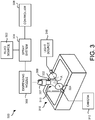
- FIG. 3 illustrates a fluid dispensing system 300 according to yet another aspect.
- the fluid dispensing system 300 may include a fluid source 302, a spray system 304, a dispensing nozzle 306 with a dispensing barrel 307 and end 309, a controller 308, a camera 312, a drain pan 316, and a light source 318 similar to those described above with respect to FIG. 1 .
- the camera 312 and the light source 318 may be oriented along a first axis A.
- the dispensing nozzle 306 may be correspondingly positioned with respect to the camera 312 such that a fluid pattern 310 dispensed by the dispensing nozzle 306 is also aligned along the first axis A.
- the fluid dispensing system may include a first polarizing filter 322 located between the light source 318 and the fluid pattern 310 produced by the dispensing nozzle 306.
- the fluid dispensing system may also include a second polarizing filter 324 located between the fluid pattern 310 produced by the dispensing nozzle 306 and the camera 312.
- the first polarizing filter 322 and second polarizing filter 324 may be linear polarizers, such as a quarter-wave plate, a half-wave plate, or another type of wave plate.
- the fluid in the fluid pattern 310 may polarize light that passes through the fluid in a known direction or manner.
- the fluid may cause a phase-shift of a quarter-wavelength in light that passes through the fluid.
- the first polarizing filter 322 and the second polarizing filter 324 may be configured to improve the contrast of the image captured by the camera 312 based on the polarization properties of the fluid.
- the light may become linearly polarized in a particular direction. Some light may continue to travel through fluid pattern 310 and undergo a fixed phase shift, such as by 45° or 90°.
- the second polarizing filter 324 may be aligned orthogonal to the direction of polarization of the fluid in the fluid pattern 310. This configuration would limit transmission of light that passes through the second polarizing filter except for light that has had its polarization altered by passing through the fluid of the fluid pattern 310. Therefore, the fluid pattern 310 may appear lighter than the background.
- FIG. 4 illustrates a fluid dispensing system 400 according to yet another aspect.
- the fluid dispensing system 400 may include a fluid source 402, a spray system 404, a dispensing nozzle 406 with a dispensing barrel 407 and end 409, a controller 408, a camera 412, and a drain pan 416 similar to those described above with respect to FIG. 1 .
- the fluid dispensing system 400 may include a first light source 418 and a second light source 426.
- the first light source 418 may be located along a first axis A defined by the camera 412 and the a fluid pattern 410 produced by the dispensing nozzle 406.
- the second light source 426 may be located along a second axis B that intersects with the first axis A at the fluid pattern 410.
- the second axis B may be perpendicular to or obtuse to the first axis A.
- the fluid of the fluid pattern 410 may be dispensed from the dispensing nozzle 406 in a form that may have retroreflective properties.
- the fluid may reflect light back to its source with a minimum amount of scattering.
- the retroreflective properties may be a result of the shape of the fluid or surface properties of the fluid.
- the fluid may be dispensed in as a spray with spherical droplets, which may be retroreflective.
- a light source located along the same axis as the camera may give higher illumination of the droplets compared to a light source located along a different axis.
- the first light source 418 may provide more illumination to the fluid pattern 410 compared to the second light source 426 from the perspective of the camera 412.
- a difference or ratio in the magnitude of illumination provided by the first light source 418 and the second light source 426 may be indicative of the size, the shape, and/or the quality of atomization of the fluid as it is being dispensed.
- the first light source 418 may be configured to emit light with a first wavelength, e.g., red
- the second light source 426 may be configured to emit light with a second wavelength different than the first wavelength, e.g., blue.
- the retroreflective properties of the fluid may result in the color captured by the camera 412 to have more red light than blue light, which may indicate a higher sphericity of the fluid. If the color captured by the camera 412 appears to have more equal levels of red light and blue light or higher levels of blue light than red light, the controller 408 may determine the sphericity of the fluid is lower.
- fluid dispensing systems 100, 200, 300, and 400 mentioned above with reference to FIGS. 1-4 have been described as separate aspects, one or more features of the fluid dispensing systems 100, 200, 300, and 400 may be combined to improve the quality of an image of a fluid pattern captured by a camera 112.
- FIG. 5 illustrates a process 500 for controlling a fluid dispensing system.
- the process 500 may be executed by the controller 108, 208, 308 or 408.
- the process 500 starts at step 502.
- the controller 108 may forward instructions to the spray system 104 and/or the dispensing nozzle 106 to dispense the fluid according to one or more first system parameters that are intended to produce a first fluid pattern.
- the one or more first system parameters may include any parameter relating to the operation of the fluid dispensing system 100, such as a fluid pressure, velocity, and/or volume of the fluid provided to the dispensing nozzle 106, the horizontal and/or vertical position of the dispensing nozzle 106, the rotational orientation of the dispensing nozzle 106, and the pulse timing and/or pulse duration of fluid dispensed from the dispensing nozzle 106.
- the one or more first system parameters may further include a direction (e.g., horizontal direction) and/or velocity (e.g., horizontal velocity) of movement of the dispensing nozzle 106 relative to the substrate or vice versa.
- the dispensing nozzle 106 may then dispense the fluid according to the one or more first system parameters.
- the stream or spray dispensed by the dispensing nozzle 106 may have a first actual fluid pattern, which may or may not match the intended first fluid pattern.
- the controller 108 may forward instructions as a result of an operator input.
- images of the stream or spray of the fluid showing the actual fluid pattern are received by the controller 108 from one or more cameras 112.
- the camera(s) 112 may be continuously capturing and forwarding images of the actual fluid pattern at predetermined time intervals.
- the controller 108 may receive a video stream of the actual fluid pattern.
- the controller 108 may forward instructions to the camera(s) 112 to capture images of the stream or spray of the fluid at a particular point in time.
- the camera(s) 112 may capture one or more images or video streams of the actual fluid pattern from multiple angles.
- a first camera 112 may capture one or more images or a video stream of the actual fluid pattern from a first angle and a second camera 112 may capture one or more images or a video stream of the actual fluid pattern from a second, different angle.
- the first angle may be perpendicular to the second angle.
- the camera(s) 112 may be configured to move between one or more positions relative to the actual fluid pattern (e.g., rotate partially or fully around the actual fluid pattern) and thereby capture one or more images or a video stream of the actual fluid pattern from multiple angles.
- the one or more images or video streams depicting the actual fluid pattern from multiple angles may subsequently be provided to and received by the controller 108.
- the controller 108 may determine first actual fluid pattern information of the first actual fluid pattern.
- the controller 108 may determine the actual fluid pattern information based on the images received from the camera 112.
- the actual fluid pattern information may include at least one of a dimension (e.g., a width) of the actual fluid pattern, a shape of the actual fluid pattern, a horizontal or vertical offset of the actual fluid pattern, a density of the actual fluid pattern, a quality of the actual fluid pattern, a size of droplets of the actual fluid pattern, a rotational orientation of the actual fluid pattern, or other characteristic of the actual fluid pattern.
- An offset of the actual fluid pattern may refer to an offset in position of the actual fluid pattern from a desired alignment. For example, the actual fluid pattern may be centered 2 mm away from a desired location.
- the controller 108 may determine the actual fluid pattern information based on various image processing algorithms, such as high-pass filtering to determine edges of the actual fluid pattern.
- the controller 108 determines a three-dimensional model of the actual fluid pattern based on the one or more images or video streams of the actual fluid pattern received from the camera 112.
- the three-dimensional model may be created, for example, using known techniques to recognize boundaries and/or features in each of the images of the actual fluid pattern and triangulating (and/or using other tomographic methods) the recognized boundaries and/or features to create a representation of the actual fluid pattern within the model.
- the three-dimensional model provides a representation of the actual fluid pattern, the aforementioned actual fluid pattern information is determined based on the three-dimensional model.
- the controller 108 may compare the first actual fluid pattern information to first fluid pattern information for the intended first fluid pattern that corresponds to the one or more first system parameters. That is, the observed first actual fluid pattern information may be compared to the first fluid pattern information that is expected using the one or more first system parameters.
- the first fluid pattern information may be the same type of information described above with respect to the actual fluid pattern information except as related to the intended first fluid pattern. For example, if the first actual fluid pattern information represents a width of the actual fluid pattern, the width of the actual fluid pattern may be compared to the desired width of the intended first fluid pattern represented in the first fluid pattern information.
- the controller 108 may calculate a difference between a magnitude of the first actual fluid pattern information and the first fluid pattern information. In other aspects, the controller 108 may calculate a ratio between the first actual fluid pattern information and the first fluid pattern information.
- the controller 108 may determine, based on the comparison of the first actual fluid pattern information to the first fluid pattern information, that the first actual fluid pattern is outside tolerances set for the first fluid pattern.
- the tolerances set for the first fluid pattern may include at least one of a desired width of the first fluid pattern, a desired shape of the first fluid pattern, a permissible offset of the first fluid pattern, a desired density of the first fluid pattern, a desired quality of the first fluid pattern, a desired size of droplets of the first fluid pattern, a desired rotational orientation of the first fluid pattern, or other design or process limit for the first fluid pattern.
- the controller 108 may determine that the width of the first actual fluid pattern at a particular height is greater than a tolerance of the first fluid pattern.
- the controller 108 may determine that the sphericity of the droplets in the first actual fluid pattern is lower than a tolerance of the first fluid pattern.
- the first actual fluid pattern information being outside a tolerance of the first fluid pattern may indicate that one or more system parameters of the fluid dispensing system 100 may need to be adjusted.
- the controller 108 may determine instructions to change system parameters of the fluid dispensing system 100 to dispense fluid with one or more second system parameters that may be different than the one or more first system parameters.
- the controller 108 may determine instructions to reduce the fluid pressure at which fluid is provided to the dispensing nozzle 206, which may thereby reduce the width of the fluid pattern, preferably to a width that is within a width tolerance.
- the controller 108 may forward instructions to the spray system 104 and/or dispensing nozzle 106 to dispense the fluid according to the at least one second system parameters, which may cause the dispensing nozzle 106 to produce a second actual fluid pattern different than the first actual fluid pattern.
- the second system parameters may include any parameter relating to the operation of the fluid dispensing system 100 and may include a fluid pressure, velocity, and/or volume of the fluid provided to the dispensing nozzle 106, the horizontal and/or vertical position of the dispensing nozzle 106, the rotational orientation of the dispensing nozzle 106, and the pulse timing and/or pulse duration of fluid dispensed from the dispensing nozzle 106.
- the dispensing nozzle 106 and/or substrate may be configured to move in at least one horizontal direction.
- the second system parameters may be a direction and/or horizontal velocity of the dispensing nozzle 106 and/or substrate.
- the spray system 104 and/or dispensing nozzle 106 may use the second system parameters and subsequently dispense the fluid according to the second actual fluid pattern that matches closer to the first fluid pattern.
- the controller 108 may forward an alert to an operator of the fluid dispensing system 100.
- the alert may indicate the actual fluid pattern is outside tolerances set for the first fluid pattern.
- the alert may contain suggested changes to system parameters of the fluid dispensing system 100 and to dispense the fluid according to different system parameters.
- An operator of the fluid dispensing system 100 may manually adjust system parameters to dispense the fluid with a different actual fluid pattern in step 512.
- the controller 108, 208, 308, and 408 may be a processor-based device that operates by executing computer-executable instructions read from a non-transitory computer-readable medium.
- the non-transitory computer-readable medium may be a hard drive, flash drive, RAM, ROM, optical memory, magnetic memory, combinations thereof, or any other machine-readable medium known in the art.
- the controller 108, 208, 308, and 408 may be single device or a plurality of devices. Further, the controller 108, 208, 308, and 408 may be a dedicated controller or may be implemented within an existing controller also serving one or more other functions, e.g., engine or machine speed control. It will be appreciated that any of the processes or functions described herein may be effected or controlled by the controller 108, 208, 308, and 408.
Landscapes
- Chemical & Material Sciences (AREA)
- Physics & Mathematics (AREA)
- General Health & Medical Sciences (AREA)
- Life Sciences & Earth Sciences (AREA)
- Analytical Chemistry (AREA)
- Biochemistry (AREA)
- Health & Medical Sciences (AREA)
- General Physics & Mathematics (AREA)
- Immunology (AREA)
- Pathology (AREA)
- Dispersion Chemistry (AREA)
- Mathematical Physics (AREA)
- Spray Control Apparatus (AREA)
- Length Measuring Devices By Optical Means (AREA)
- Coating Apparatus (AREA)
Claims (15)
- Fluidausgabesystem (100; 300; 400), das Folgendes aufweist:eine Quelle (102; 302; 402) eines Fluids;eine Ausgabedüse (106; 306; 406) und ein Sprühsystem (104; 304; 404), das das Fluid aus der Quelle (102; 302; 402) des Fluids unter Verwendung von Systemparametern für das Sprühsystem der Ausgabedüse (106; 306; 406) zuführt, wobei das Sprühsystem (104; 304; 404) und die Ausgabedüse (106; 306; 406) zum Ausgeben des Fluids als einen Strom oder einen Sprühstrahl als ein Ist-Fluidmuster gemäß ein oder mehr ersten Systemparametern gestaltet ist, die zum Erzeugen eines ersten Fluidmusters (110; 310; 410) vorgesehen sind;eine erste Lichtquelle (118; 318; 418), die funktionell konfiguriert ist, um Licht durch ein aus der Ausgabedüse (106; 306; 406) ausgegebenes erstes Ist-Fluidmuster abzustrahlen, wobei die erste Lichtquelle (118; 318; 418) positioniert ist, um dem ersten Ist-Fluidmuster gegenüberzuliegen, um das abgestrahlte Licht durch das erste Ist-Fluidmuster zu leiten;eine Kamera (112; 312; 412), die zum Aufnehmen von ein oder mehr Bildern des aus der Ausgabedüse (106; 306; 406) ausgegebenen ersten Ist-Fluidmusters konfiguriert ist; undeine Steuereinheit (108; 318; 418), die funktionell mit dem Sprühsystem (104; 304; 404) und der Kamera (112; 312; 412) verbunden ist, wobei die Steuereinheit konfiguriert ist zum:Weiterleiten von Anweisungen an das Sprühsystem (104; 304; 404) zum Ausgeben des Fluids gemäß den ein oder mehr ersten Systemparametern zum Erzeugen des ersten Ist-Fluidmusters;Empfangen der ein oder mehr Bilder des ersten Ist-Fluidmusters von der Kamera (112; 312; 412);auf Basis der empfangenen ein oder mehr Bilder Bestimmen eines dreidimensionalen Modells des ersten Ist-Fluidmusters und Bestimmen erster Ist-Fluidmuster-Informationen des ersten Ist-Fluidmusters auf Basis des dreidimensionalen Modells;Vergleichen der ersten Ist-Fluidmuster-Informationen mit ersten Fluidmusterinformationen für das erste Fluidmuster;auf Basis des Vergleichs der ersten Ist-Fluidmuster-Informationen mit den ersten Fluidmusterinformationen Bestimmen, dass das erste Ist-Fluidmuster außerhalb von für das erste Fluidmuster festgesetzten Toleranzen ist; undauf Basis der Bestimmung, dass das erste Ist-Fluidmuster außerhalb von für das erste Fluidmuster festgesetzten Toleranzen ist, Weiterleiten von ein oder mehr zweiten Systemparametern an das Sprühsystem (104) zum Erzeugen eines zweiten Ist-Fluidmusters.
- Fluidausgabesystem nach Anspruch 1, wobei die erste Lichtquelle (118; 318; 418) funktionell mit der Steuereinheit (108; 308; 408) gekoppelt ist.
- Fluidausgabesystem nach Anspruch 1 oder 2, wobei:die Kamera (112) und die erste Lichtquelle (118) jeweils an verschiedenen vertikalen Positionen vertikal positioniert sind; unddie horizontale Position der Ausgabedüse (106) zwischen der horizontalen Position der Kamera (112) und der horizontalen Position der ersten Lichtquelle (108) ist.
- Fluidausgabesystem nach Anspruch 1 oder 2, wobei die Kamera (112) und das erste Ist-Fluidmuster an einer ersten Achse entlang liegen und die erste Lichtquelle (108) und das erste Ist-Fluidmuster an einer zweiten Achse entlang liegen, die sich an dem ersten Ist-Fluidmuster mit der ersten Achse schneidet.
- Fluidausgabesystem nach Anspruch 1 oder 2, wobei das erste Ist-Fluidmuster zwischen der Kamera (312) und der ersten Lichtquelle (318) liegt, wobei das Fluidausgabesystem ferner Folgendes aufweist:ein erstes Polarisationsfilter (322) mit einer ersten Polarisationsrichtung, wobei das erste Polarisationsfilter zwischen dem ersten Ist-Fluidmuster und der ersten Lichtquelle (318) positioniert ist; undein zweites Polarisationsfilter (324) mit einer zweiten Polarisationsrichtung, die zu der ersten Polarisationsrichtung orthogonal ist, wobei das zweite Polarisationsfilter zwischen dem ersten Ist-Fluidmuster und der Kamera (312) positioniert ist.
- Fluidausgabesystem nach Anspruch 1 oder 2, das ferner Folgendes aufweist:
eine zweite Lichtquelle (246), die funktionell mit der Steuereinheit (408) gekoppelt ist, wobei die zweite Lichtquelle (246) zum Abstrahlen von Licht durch das erste Ist-Fluidmuster konfiguriert ist, wobei:das erste Ist-Fluidmuster, die Kamera (412) und die erste Lichtquelle (418) an einer ersten Achse entlang liegen;das erste Ist-Fluidmuster und die zweite Lichtquelle (426) an einer zweiten Achse entlang liegen, die sich an dem ersten Ist-Fluidmuster mit der ersten Achse schneidet; unddie erste Lichtquelle (418) Licht mit einer ersten Wellenlänge abstrahlt und die zweite Lichtquelle (426) Licht mit einer zweiten Wellenlänge abstrahlt, die von der ersten Wellenlänge verschieden ist. - Fluidausgabesystem nach Anspruch 1, wobei die ersten Ist-Fluidmuster-Informationen wenigstens eines von Folgenden sind: eine Breite des ersten Ist-Fluidmusters, eine Form des ersten Ist-Fluidmusters, ein Versatz des ersten Ist-Fluidmusters, eine Dichte des ersten Ist-Fluidmusters, eine Qualität des ersten Ist-Fluidmusters, eine Größe von Tröpfchen des ersten Ist-Fluidmusters und eine Drehausrichtung des ersten Ist-Fluidmusters.
- Fluidausgabesystem nach Anspruch 1, wobei die ein oder mehr zweiten Systemparameter wenigstens eines der Folgenden aufweisen: einen Fluiddruck des Fluids, ein Volumen des Fluids, eine Geschwindigkeit des Fluids, eine horizontale Position der Ausgabedüse, eine vertikale Position der Ausgabedüse, eine Drehausrichtung der Ausgabedüse, eine zeitliche Abstimmung zwischen Impulsen der Ausgabedüse und einer Impulsdauer der Ausgabedüse.
- Fluidausgabesystem nach Anspruch 1, wobei:die ein oder mehr Bilder des ersten Ist-Fluidmusters wenigstens ein Bild des ersten Ist-Fluidmusters aus einem ersten Winkel und wenigstens ein Bild des ersten Ist-Fluidmusters aus einem zweiten Winkel, der von dem ersten Winkel verschieden ist, aufweisen, unddie Steuereinheit zum Bestimmen des dreidimensionalen Modells des ersten Ist-Fluidmusters auf Basis des wenigstens einen Bilds des ersten Ist-Fluidmusters aus dem ersten Winkel und des wenigstens einen Bilds des ersten Ist-Fluidmusters aus dem zweiten Winkel konfiguriert ist.
- Fluidausgabesystem nach Anspruch 1, das ferner eine zweite Kamera aufweist, die funktionell mit der Steuereinheit verbunden ist, wobei:die ein oder mehr Bilder des ersten Ist-Fluidmusters von der Kamera aus einem ersten Winkel in Bezug auf das erste Ist-Fluidmuster sind;die zweite Kamera zum Aufnehmen eines zweiten Satzes von ein oder mehr Bildern des ersten Ist-Fluidmusters aus einem zweiten Winkel in Bezug auf das erste Ist-Fluidmuster konfiguriert ist, wobei der zweite Winkel von dem ersten Winkel verschieden ist; unddie Steuereinheit ferner konfiguriert ist zum:Empfangen des zweiten Satzes von ein oder mehr Bildern des ersten Ist-Fluidmusters von der zweiten Kamera; undBestimmen des dreidimensionalen Modells des ersten Ist-Fluidmusters auf Basis der ein oder mehr Bilder des ersten Ist-Fluidmusters von der Kamera und des zweiten Satzes der ein oder mehr Bilder des ersten Ist-Fluidmusters von der zweiten Kamera.
- Verfahren zum Steuern eines Fluidausgabesystems, wobei das Verfahren Folgendes aufweist:Weiterleiten von Anweisungen an ein Sprühsystem des Fluidausgabesystems zum Ausgeben eines Fluids durch eine Ausgabedüse gemäß ein oder mehr ersten Systemparametern, die zum Erzeugen eines ersten Fluidmusters vorgesehen sind;Abstrahlen von Licht aus einer ersten Lichtquelle, die dem ersten Ist-Fluidmuster gegenüberliegt, das von der Ausgabedüse ausgegeben wird, um das abgestrahlte Licht durch das erste Ist-Fluidmuster zu leiten;Empfangen von ein oder mehr Bildern des durch die Ausgabedüse ausgegebenen ersten Ist-Fluidmusters von einer Kamera;auf Basis der empfangenen ein oder mehr Bilder Bestimmen eines dreidimensionalen Modells des ersten Ist-Fluidmusters und Bestimmen erster Ist-Fluidmuster-Informationen des ersten Ist-Fluidmusters auf Basis des dreidimensionalen Modells;Vergleichen der ersten Ist-Fluidmuster-Informationen mit ersten Fluidmusterinformationen für das erste Fluidmuster;auf Basis des Vergleichs der ersten Ist-Fluidmuster-Informationen mit den ersten Fluidmusterinformationen Bestimmen, dass das erste Ist-Fluidmuster außerhalb von für das erste Fluidmuster festgesetzten Toleranzen ist; undauf Basis der Bestimmung, dass das erste Ist-Fluidmuster außerhalb von für das erste Fluidmuster festgesetzten Toleranzen ist, Weiterleiten von ein oder mehr zweiten Systemparametern an das Sprühsystem zum Erzeugen eines zweiten Ist-Fluidmusters.
- Verfahren nach Anspruch 11, wobei die ersten Ist-Fluidmuster-Informationen wenigstens eines von Folgenden sind: eine Breite des ersten Ist-Fluidmusters, eine Form des ersten Ist-Fluidmusters, ein Versatz des ersten Ist-Fluidmusters, eine Dichte des ersten Ist-Fluidmusters, eine Qualität des ersten Ist-Fluidmusters, eine Größe von Tröpfchen des ersten Ist-Fluidmusters und eine Drehausrichtung des ersten Ist-Fluidmusters.
- Verfahren nach Anspruch 11, wobei die ein oder mehr zweiten Systemparameter wenigstens eines der Folgenden aufweisen: einen Fluiddruck des Fluids, ein Volumen des Fluids, eine Geschwindigkeit des Fluids, eine horizontale Position der Ausgabedüse, eine vertikale Position der Ausgabedüse, eine Drehausrichtung der Ausgabedüse, eine zeitliche Abstimmung zwischen Impulsen der Ausgabedüse und eine Impulsdauer der Ausgabedüse.
- Verfahren nach Anspruch 11, die ferner das Pflegen des Modells des ersten Ist-Fluidmusters auf Basis von wenigstens den ein oder mehr Bildern aufweist.
- Verfahren nach Anspruch 11, wobei:die ein oder mehr Bilder des ersten Ist-Fluidmusters wenigstens ein Bild des ersten Ist-Fluidmusters aus einem ersten Winkel und wenigstens ein Bild des ersten Ist-Fluidmusters aus einem zweiten Winkel, der von dem ersten Winkel verschieden ist, aufweisen,wobei das dreidimensionale Modell des ersten Ist-Fluidmusters auf Basis des wenigstens einen Bilds des ersten Ist-Fluidmusters aus dem ersten Winkel und des wenigstens einen Bilds des ersten Ist-Fluidmusters aus dem zweiten Winkel ist.
Applications Claiming Priority (2)
| Application Number | Priority Date | Filing Date | Title |
|---|---|---|---|
| US201562250704P | 2015-11-04 | 2015-11-04 | |
| PCT/US2016/060223 WO2017079366A1 (en) | 2015-11-04 | 2016-11-03 | Method and system for controlling a fluid pattern of a dispensed fluid |
Publications (2)
| Publication Number | Publication Date |
|---|---|
| EP3370885A1 EP3370885A1 (de) | 2018-09-12 |
| EP3370885B1 true EP3370885B1 (de) | 2020-12-30 |
Family
ID=57570107
Family Applications (1)
| Application Number | Title | Priority Date | Filing Date |
|---|---|---|---|
| EP16812885.8A Not-in-force EP3370885B1 (de) | 2015-11-04 | 2016-11-03 | Verfahren und vorrichtung zur kontrolle eines sprühstrahls |
Country Status (6)
| Country | Link |
|---|---|
| US (1) | US10758926B2 (de) |
| EP (1) | EP3370885B1 (de) |
| JP (1) | JP6864680B2 (de) |
| KR (1) | KR20180080254A (de) |
| CN (1) | CN108348940B (de) |
| WO (1) | WO2017079366A1 (de) |
Families Citing this family (35)
| Publication number | Priority date | Publication date | Assignee | Title |
|---|---|---|---|---|
| DE102016206995A1 (de) * | 2016-04-25 | 2017-10-26 | Rehm Thermal Systems Gmbh | Vorrichtung und Verfahren zur Vermessung eines Lackstrahls zum Beschichten von Platinen |
| US9789497B1 (en) | 2016-06-20 | 2017-10-17 | Nordson Corporation | Systems and methods for applying a liquid coating to a substrate |
| CN109564237B (zh) * | 2016-06-30 | 2022-12-13 | 拜克门寇尔特公司 | 物质分配评估系统 |
| TWI682813B (zh) * | 2016-11-29 | 2020-01-21 | 荷蘭商耐克創新有限合夥公司 | 多噴嘴工具以及使用多噴嘴工具塗覆材料的方法 |
| DE102017203192A1 (de) * | 2017-02-28 | 2018-08-30 | Siemens Aktiengesellschaft | Verfahren zur Aerosoldeposition und Vorrichtung |
| DE102017208577A1 (de) * | 2017-05-19 | 2018-11-22 | Robert Bosch Gmbh | Verfahren zur Ansteuerung einer Abgabeeinheit und/oder einer landwirtschaftlichen Arbeitsmaschine mit der Abgabeeinheit |
| EP3706920B1 (de) * | 2017-11-10 | 2026-04-29 | Nordson Corporation | Systeme und verfahren für verbesserte beschichtungsausgabekontrolle |
| KR102022091B1 (ko) * | 2018-01-03 | 2019-11-05 | 티티앤에스 주식회사 | 노즐에서 분사되는 코팅액의 폭 제어 방법 및 장치 |
| US10921235B2 (en) * | 2018-09-17 | 2021-02-16 | Honeywell International Inc. | Foul-resistant coating of windows for optical particle sensing |
| WO2020178663A1 (en) | 2019-03-01 | 2020-09-10 | Precision Planting Llc | Agricultural spraying system |
| US20220167606A1 (en) * | 2019-03-29 | 2022-06-02 | Basf Agro Trademarks Gmbh | Method for plantation treatment of a plantation field |
| KR102163176B1 (ko) * | 2019-04-30 | 2020-10-08 | 주식회사 프로텍 | 3차원 스캐너를 이용한 점성 용액 디스펜싱 장치 |
| US11684938B2 (en) | 2019-07-19 | 2023-06-27 | Agco Corporation | Spray pattern monitoring |
| JP6891927B2 (ja) * | 2019-08-21 | 2021-06-18 | ダイキン工業株式会社 | 空気処理装置 |
| EP4033895B1 (de) | 2019-09-27 | 2026-01-14 | Precision Planting LLC | Landwirtschaftliches sprühsystem |
| US11484183B2 (en) | 2019-09-30 | 2022-11-01 | Midea Group Co., Ltd. | Dishwasher with image-based object sensing |
| US11259681B2 (en) | 2019-09-30 | 2022-03-01 | Midea Group Co., Ltd | Dishwasher with image-based diagnostics |
| US11191416B2 (en) * | 2019-09-30 | 2021-12-07 | Midea Group Co., Ltd. | Dishwasher with image-based position sensor |
| US11026559B2 (en) | 2019-09-30 | 2021-06-08 | Midea Group Co., Ltd. | Dishwasher with image-based fluid condition sensing |
| US11399690B2 (en) | 2019-09-30 | 2022-08-02 | Midea Group Co., Ltd. | Dishwasher with cam-based position sensor |
| US11464389B2 (en) | 2019-09-30 | 2022-10-11 | Midea Group Co., Ltd. | Dishwasher with image-based detergent sensing |
| US11202550B2 (en) | 2019-11-20 | 2021-12-21 | Midea Group Co., Ltd. | Dishwasher thermal imaging system |
| US11185209B2 (en) | 2019-11-20 | 2021-11-30 | Midea Group Co., Ltd. | Dishwasher steam generator |
| CN110976124B (zh) * | 2019-12-02 | 2020-12-18 | 平庆义 | 一种涂装设备用喷淋方法 |
| WO2021168174A1 (en) * | 2020-02-20 | 2021-08-26 | Nordson Corporation | Improved fluid dispensing process control using machine learning and system implementing the same |
| US20210323015A1 (en) * | 2020-04-17 | 2021-10-21 | Cnh Industrial Canada, Ltd. | System and method to monitor nozzle spray quality |
| US11261076B1 (en) * | 2020-08-13 | 2022-03-01 | Pepsico, Inc. | Beverage dispense monitoring with camera |
| US12214377B2 (en) | 2020-12-02 | 2025-02-04 | Precision Valve & Automation, Inc. | Conformal coating process with thickness control |
| JP7695786B2 (ja) * | 2020-12-23 | 2025-06-19 | 芝浦機械株式会社 | ノズル検査システム及びノズル検査方法 |
| CN115318572A (zh) * | 2021-05-11 | 2022-11-11 | 一汽-大众汽车有限公司 | 一种涂胶形状调控方法和设备 |
| EP4359146A2 (de) | 2021-06-24 | 2024-05-01 | Nordson Corporation | Kontaktloser ultraschalldüsenreiniger mit automatischer verstopfungserkennung in einem geschlossenen regelkreis |
| IT202100024266A1 (it) * | 2021-09-21 | 2023-03-21 | Ger Elettr S R L | Apparato di controllo perfezionato per un impianto di spruzzatura |
| WO2023150346A1 (en) * | 2022-02-07 | 2023-08-10 | Spraying Systems Co. | Spraying system with sensor air shield |
| TW202517354A (zh) * | 2023-07-13 | 2025-05-01 | 美商能多順股份有限公司 | 側面噴嘴檢查的系統和方法 |
| CN121068177A (zh) * | 2024-06-05 | 2025-12-05 | 台达电子工业股份有限公司 | 喷嘴参数测量器、测量方法以及测量系统 |
Family Cites Families (22)
| Publication number | Priority date | Publication date | Assignee | Title |
|---|---|---|---|---|
| JPS57201560A (en) * | 1981-03-27 | 1982-12-10 | Biieru Tekunorojii Ltd | Method and device for spraying medium |
| US5312039A (en) * | 1992-06-22 | 1994-05-17 | Vlsi Technology, Inc. | Electro-optic monitor for fluid spray pattern |
| US5905568A (en) * | 1997-12-15 | 1999-05-18 | The United States Of America As Represented By The Administrator Of The National Aeronautics And Space Administration | Stereo imaging velocimetry |
| US6457655B1 (en) * | 1999-09-03 | 2002-10-01 | Nordson Corporation | Method and apparatus for measuring and adjusting a liquid spray pattern |
| EP1395939A4 (de) * | 2001-05-24 | 2006-06-07 | New Objective Inc | Verfahren und vorrichtung für elektrospray mit rückkopplungsregelung |
| WO2003062129A2 (en) * | 2002-01-22 | 2003-07-31 | Nordson Corporation | Method and apparatus for detecting a liquid spray pattern |
| FR2836620B1 (fr) * | 2002-02-28 | 2004-04-16 | Snecma Services | Instrument de projection thermique |
| NL1024402C2 (nl) * | 2003-09-30 | 2005-03-31 | Lely Entpr Ag | Inrichting en werkwijze voor het aanbrengen van een fluïdum op een speen van een melkdier. |
| DE10361018C9 (de) * | 2003-12-23 | 2021-03-04 | QUISS Qualitäts-Inspektionssysteme und Service GmbH | Verfahren zum Erkennen einer auf einem Substrat aufzubringenden Struktur mit mehreren Kameras sowie eine Vorrichtung hierfür |
| JP4606208B2 (ja) * | 2004-07-27 | 2011-01-05 | プラントエンジニアリング株式会社 | 流体噴射シミュレーション方法 |
| US8154711B1 (en) * | 2004-10-01 | 2012-04-10 | Ingo Werner Scheer | Spray diagnostic and control method and system |
| US7867576B2 (en) * | 2005-08-01 | 2011-01-11 | Leonard Levin | Method and apparatus for monitoring a pattern of an applied liquid |
| CA2993208C (en) * | 2007-11-15 | 2021-01-26 | Garrett Thermal Systems Limited | Particle detection |
| CN103889488B (zh) | 2011-10-28 | 2017-03-01 | 皇家飞利浦有限公司 | 对气溶胶流的分析与控制 |
| US11745201B2 (en) * | 2012-06-11 | 2023-09-05 | General Electric Company | Spray plume position feedback for robotic motion to optimize coating quality, efficiency, and repeatability |
| US9868254B2 (en) * | 2014-05-30 | 2018-01-16 | Apple Inc. | Method and apparatus for three dimensional printing of colored objects |
| ES2661097T3 (es) * | 2015-01-26 | 2018-03-27 | Inman S.R.L. | Dispositivo y procedimiento para controlar un patrón de pulverización |
| DE102015111889B4 (de) * | 2015-07-22 | 2020-02-27 | Andreas Reichhardt | Verfahren zur Prüfung einer landwirtschaftlichen Sprüheinrichtung |
| CN106696292B (zh) * | 2015-07-31 | 2019-03-05 | 三纬国际立体列印科技股份有限公司 | 立体打印装置 |
| US10639718B2 (en) * | 2016-03-03 | 2020-05-05 | Desktop Metal, Inc. | Molten material interfaces for magnetohydrodynamic metal manufacturing |
| US10562054B2 (en) | 2016-03-11 | 2020-02-18 | Precision Valve & Automation, Inc. | Automatically controlling a liquid spray pattern |
| DE102016206995A1 (de) | 2016-04-25 | 2017-10-26 | Rehm Thermal Systems Gmbh | Vorrichtung und Verfahren zur Vermessung eines Lackstrahls zum Beschichten von Platinen |
-
2016
- 2016-11-03 JP JP2018522649A patent/JP6864680B2/ja not_active Expired - Fee Related
- 2016-11-03 WO PCT/US2016/060223 patent/WO2017079366A1/en not_active Ceased
- 2016-11-03 EP EP16812885.8A patent/EP3370885B1/de not_active Not-in-force
- 2016-11-03 CN CN201680064300.3A patent/CN108348940B/zh not_active Expired - Fee Related
- 2016-11-03 KR KR1020187014978A patent/KR20180080254A/ko not_active Ceased
- 2016-11-03 US US15/768,006 patent/US10758926B2/en not_active Expired - Fee Related
Non-Patent Citations (1)
| Title |
|---|
| None * |
Also Published As
| Publication number | Publication date |
|---|---|
| WO2017079366A1 (en) | 2017-05-11 |
| EP3370885A1 (de) | 2018-09-12 |
| US20180304293A1 (en) | 2018-10-25 |
| US10758926B2 (en) | 2020-09-01 |
| JP6864680B2 (ja) | 2021-04-28 |
| CN108348940B (zh) | 2021-08-03 |
| JP2018535090A (ja) | 2018-11-29 |
| KR20180080254A (ko) | 2018-07-11 |
| CN108348940A (zh) | 2018-07-31 |
Similar Documents
| Publication | Publication Date | Title |
|---|---|---|
| EP3370885B1 (de) | Verfahren und vorrichtung zur kontrolle eines sprühstrahls | |
| US11471977B2 (en) | Monitoring a thermal cutting process | |
| US12104893B2 (en) | Three-dimensional measurement device | |
| US10864730B2 (en) | Electrohydrodynamic printing apparatus | |
| CN102854733B (zh) | 发光装置及相关投影系统 | |
| JP2016512330A5 (de) | ||
| DE102012219387B4 (de) | Beleuchtungsvorrichtung mit Pumplichtquelle und Leuchtstoffanordnung und Verfahren zum Betreiben einer solchen Beleuchtungsvorrichtung | |
| EP2026104A2 (de) | Abstandmessungsverfahren und -vorrichtung und mit dieser Vorrichtung ausgestattetes Fahrzeug | |
| KR20160057166A (ko) | 거리영상 측정용 카메라 및 그 동작방법 | |
| TWI711870B (zh) | 具有可調光強度的深度產生系統 | |
| DE102007007534A1 (de) | Vorrichtung und Verfahren zum Formenmessen | |
| US12223735B2 (en) | Vehicle camera vision and control system and method | |
| KR102686393B1 (ko) | 3차원 스캐너 및 3차원 스캐닝 방법 | |
| CN111487765B (zh) | 束扫描引擎和具有多个束扫描仪的显示系统 | |
| EP4518582A1 (de) | Entfernungsmessungs- und sicherheitssystem für eine leuchte | |
| CN104635411A (zh) | 投影显示系统 | |
| KR102091829B1 (ko) | 광 각도 분해능을 향상시킨 가변 패턴 생성장치 | |
| CN118696605A (zh) | 使用多个led阵列的颜色校正 | |
| CN118961576A (zh) | 部件表面检查和照明系统 | |
| KR20130046885A (ko) | 영상 촬영 장치 | |
| JP2016018559A (ja) | 物体検出用撮像システム | |
| CN105258655A (zh) | 一种重构目标表面的三维轮廓的装置和方法 | |
| US20240314905A1 (en) | Machine vision systems, illumination sources for use in machine vision systems, and components for use in the illumination sources | |
| DE102016212069B4 (de) | Beleuchtungsvorrichtung mit einer lichtquelle zur emission von beleuchtungslicht | |
| DE102017213180A1 (de) | Spiegelweiche mit rotierbar gelagerter Walze |
Legal Events
| Date | Code | Title | Description |
|---|---|---|---|
| STAA | Information on the status of an ep patent application or granted ep patent |
Free format text: STATUS: UNKNOWN |
|
| STAA | Information on the status of an ep patent application or granted ep patent |
Free format text: STATUS: THE INTERNATIONAL PUBLICATION HAS BEEN MADE |
|
| PUAI | Public reference made under article 153(3) epc to a published international application that has entered the european phase |
Free format text: ORIGINAL CODE: 0009012 |
|
| STAA | Information on the status of an ep patent application or granted ep patent |
Free format text: STATUS: REQUEST FOR EXAMINATION WAS MADE |
|
| 17P | Request for examination filed |
Effective date: 20180531 |
|
| AK | Designated contracting states |
Kind code of ref document: A1 Designated state(s): AL AT BE BG CH CY CZ DE DK EE ES FI FR GB GR HR HU IE IS IT LI LT LU LV MC MK MT NL NO PL PT RO RS SE SI SK SM TR |
|
| AX | Request for extension of the european patent |
Extension state: BA ME |
|
| DAV | Request for validation of the european patent (deleted) | ||
| DAX | Request for extension of the european patent (deleted) | ||
| STAA | Information on the status of an ep patent application or granted ep patent |
Free format text: STATUS: EXAMINATION IS IN PROGRESS |
|
| 17Q | First examination report despatched |
Effective date: 20191021 |
|
| GRAP | Despatch of communication of intention to grant a patent |
Free format text: ORIGINAL CODE: EPIDOSNIGR1 |
|
| STAA | Information on the status of an ep patent application or granted ep patent |
Free format text: STATUS: GRANT OF PATENT IS INTENDED |
|
| INTG | Intention to grant announced |
Effective date: 20200630 |
|
| GRAS | Grant fee paid |
Free format text: ORIGINAL CODE: EPIDOSNIGR3 |
|
| GRAA | (expected) grant |
Free format text: ORIGINAL CODE: 0009210 |
|
| STAA | Information on the status of an ep patent application or granted ep patent |
Free format text: STATUS: THE PATENT HAS BEEN GRANTED |
|
| AK | Designated contracting states |
Kind code of ref document: B1 Designated state(s): AL AT BE BG CH CY CZ DE DK EE ES FI FR GB GR HR HU IE IS IT LI LT LU LV MC MK MT NL NO PL PT RO RS SE SI SK SM TR |
|
| REG | Reference to a national code |
Ref country code: GB Ref legal event code: FG4D |
|
| REG | Reference to a national code |
Ref country code: AT Ref legal event code: REF Ref document number: 1349410 Country of ref document: AT Kind code of ref document: T Effective date: 20210115 |
|
| REG | Reference to a national code |
Ref country code: DE Ref legal event code: R096 Ref document number: 602016050711 Country of ref document: DE |
|
| REG | Reference to a national code |
Ref country code: IE Ref legal event code: FG4D |
|
| REG | Reference to a national code |
Ref country code: SE Ref legal event code: TRGR |
|
| REG | Reference to a national code |
Ref country code: NL Ref legal event code: FP |
|
| PG25 | Lapsed in a contracting state [announced via postgrant information from national office to epo] |
Ref country code: FI Free format text: LAPSE BECAUSE OF FAILURE TO SUBMIT A TRANSLATION OF THE DESCRIPTION OR TO PAY THE FEE WITHIN THE PRESCRIBED TIME-LIMIT Effective date: 20201230 Ref country code: GR Free format text: LAPSE BECAUSE OF FAILURE TO SUBMIT A TRANSLATION OF THE DESCRIPTION OR TO PAY THE FEE WITHIN THE PRESCRIBED TIME-LIMIT Effective date: 20210331 Ref country code: NO Free format text: LAPSE BECAUSE OF FAILURE TO SUBMIT A TRANSLATION OF THE DESCRIPTION OR TO PAY THE FEE WITHIN THE PRESCRIBED TIME-LIMIT Effective date: 20210330 Ref country code: RS Free format text: LAPSE BECAUSE OF FAILURE TO SUBMIT A TRANSLATION OF THE DESCRIPTION OR TO PAY THE FEE WITHIN THE PRESCRIBED TIME-LIMIT Effective date: 20201230 |
|
| REG | Reference to a national code |
Ref country code: AT Ref legal event code: MK05 Ref document number: 1349410 Country of ref document: AT Kind code of ref document: T Effective date: 20201230 |
|
| PG25 | Lapsed in a contracting state [announced via postgrant information from national office to epo] |
Ref country code: BG Free format text: LAPSE BECAUSE OF FAILURE TO SUBMIT A TRANSLATION OF THE DESCRIPTION OR TO PAY THE FEE WITHIN THE PRESCRIBED TIME-LIMIT Effective date: 20210330 Ref country code: LV Free format text: LAPSE BECAUSE OF FAILURE TO SUBMIT A TRANSLATION OF THE DESCRIPTION OR TO PAY THE FEE WITHIN THE PRESCRIBED TIME-LIMIT Effective date: 20201230 |
|
| PG25 | Lapsed in a contracting state [announced via postgrant information from national office to epo] |
Ref country code: HR Free format text: LAPSE BECAUSE OF FAILURE TO SUBMIT A TRANSLATION OF THE DESCRIPTION OR TO PAY THE FEE WITHIN THE PRESCRIBED TIME-LIMIT Effective date: 20201230 |
|
| REG | Reference to a national code |
Ref country code: LT Ref legal event code: MG9D |
|
| PG25 | Lapsed in a contracting state [announced via postgrant information from national office to epo] |
Ref country code: RO Free format text: LAPSE BECAUSE OF FAILURE TO SUBMIT A TRANSLATION OF THE DESCRIPTION OR TO PAY THE FEE WITHIN THE PRESCRIBED TIME-LIMIT Effective date: 20201230 Ref country code: PT Free format text: LAPSE BECAUSE OF FAILURE TO SUBMIT A TRANSLATION OF THE DESCRIPTION OR TO PAY THE FEE WITHIN THE PRESCRIBED TIME-LIMIT Effective date: 20210430 Ref country code: SK Free format text: LAPSE BECAUSE OF FAILURE TO SUBMIT A TRANSLATION OF THE DESCRIPTION OR TO PAY THE FEE WITHIN THE PRESCRIBED TIME-LIMIT Effective date: 20201230 Ref country code: CZ Free format text: LAPSE BECAUSE OF FAILURE TO SUBMIT A TRANSLATION OF THE DESCRIPTION OR TO PAY THE FEE WITHIN THE PRESCRIBED TIME-LIMIT Effective date: 20201230 Ref country code: EE Free format text: LAPSE BECAUSE OF FAILURE TO SUBMIT A TRANSLATION OF THE DESCRIPTION OR TO PAY THE FEE WITHIN THE PRESCRIBED TIME-LIMIT Effective date: 20201230 Ref country code: LT Free format text: LAPSE BECAUSE OF FAILURE TO SUBMIT A TRANSLATION OF THE DESCRIPTION OR TO PAY THE FEE WITHIN THE PRESCRIBED TIME-LIMIT Effective date: 20201230 |
|
| PG25 | Lapsed in a contracting state [announced via postgrant information from national office to epo] |
Ref country code: PL Free format text: LAPSE BECAUSE OF FAILURE TO SUBMIT A TRANSLATION OF THE DESCRIPTION OR TO PAY THE FEE WITHIN THE PRESCRIBED TIME-LIMIT Effective date: 20201230 Ref country code: AT Free format text: LAPSE BECAUSE OF FAILURE TO SUBMIT A TRANSLATION OF THE DESCRIPTION OR TO PAY THE FEE WITHIN THE PRESCRIBED TIME-LIMIT Effective date: 20201230 |
|
| PG25 | Lapsed in a contracting state [announced via postgrant information from national office to epo] |
Ref country code: IS Free format text: LAPSE BECAUSE OF FAILURE TO SUBMIT A TRANSLATION OF THE DESCRIPTION OR TO PAY THE FEE WITHIN THE PRESCRIBED TIME-LIMIT Effective date: 20210430 |
|
| REG | Reference to a national code |
Ref country code: DE Ref legal event code: R097 Ref document number: 602016050711 Country of ref document: DE |
|
| PG25 | Lapsed in a contracting state [announced via postgrant information from national office to epo] |
Ref country code: AL Free format text: LAPSE BECAUSE OF FAILURE TO SUBMIT A TRANSLATION OF THE DESCRIPTION OR TO PAY THE FEE WITHIN THE PRESCRIBED TIME-LIMIT Effective date: 20201230 Ref country code: IT Free format text: LAPSE BECAUSE OF FAILURE TO SUBMIT A TRANSLATION OF THE DESCRIPTION OR TO PAY THE FEE WITHIN THE PRESCRIBED TIME-LIMIT Effective date: 20201230 |
|
| PLBE | No opposition filed within time limit |
Free format text: ORIGINAL CODE: 0009261 |
|
| STAA | Information on the status of an ep patent application or granted ep patent |
Free format text: STATUS: NO OPPOSITION FILED WITHIN TIME LIMIT |
|
| PG25 | Lapsed in a contracting state [announced via postgrant information from national office to epo] |
Ref country code: DK Free format text: LAPSE BECAUSE OF FAILURE TO SUBMIT A TRANSLATION OF THE DESCRIPTION OR TO PAY THE FEE WITHIN THE PRESCRIBED TIME-LIMIT Effective date: 20201230 |
|
| 26N | No opposition filed |
Effective date: 20211001 |
|
| PG25 | Lapsed in a contracting state [announced via postgrant information from national office to epo] |
Ref country code: ES Free format text: LAPSE BECAUSE OF FAILURE TO SUBMIT A TRANSLATION OF THE DESCRIPTION OR TO PAY THE FEE WITHIN THE PRESCRIBED TIME-LIMIT Effective date: 20201230 |
|
| PGFP | Annual fee paid to national office [announced via postgrant information from national office to epo] |
Ref country code: NL Payment date: 20211118 Year of fee payment: 6 Ref country code: DE Payment date: 20211118 Year of fee payment: 6 Ref country code: SE Payment date: 20211118 Year of fee payment: 6 |
|
| PG25 | Lapsed in a contracting state [announced via postgrant information from national office to epo] |
Ref country code: SI Free format text: LAPSE BECAUSE OF FAILURE TO SUBMIT A TRANSLATION OF THE DESCRIPTION OR TO PAY THE FEE WITHIN THE PRESCRIBED TIME-LIMIT Effective date: 20201230 |
|
| PG25 | Lapsed in a contracting state [announced via postgrant information from national office to epo] |
Ref country code: IS Free format text: LAPSE BECAUSE OF FAILURE TO SUBMIT A TRANSLATION OF THE DESCRIPTION OR TO PAY THE FEE WITHIN THE PRESCRIBED TIME-LIMIT Effective date: 20210430 |
|
| PG25 | Lapsed in a contracting state [announced via postgrant information from national office to epo] |
Ref country code: MC Free format text: LAPSE BECAUSE OF FAILURE TO SUBMIT A TRANSLATION OF THE DESCRIPTION OR TO PAY THE FEE WITHIN THE PRESCRIBED TIME-LIMIT Effective date: 20201230 |
|
| REG | Reference to a national code |
Ref country code: CH Ref legal event code: PL |
|
| GBPC | Gb: european patent ceased through non-payment of renewal fee |
Effective date: 20211103 |
|
| PG25 | Lapsed in a contracting state [announced via postgrant information from national office to epo] |
Ref country code: LU Free format text: LAPSE BECAUSE OF NON-PAYMENT OF DUE FEES Effective date: 20211103 Ref country code: BE Free format text: LAPSE BECAUSE OF NON-PAYMENT OF DUE FEES Effective date: 20211130 |
|
| REG | Reference to a national code |
Ref country code: BE Ref legal event code: MM Effective date: 20211130 |
|
| PG25 | Lapsed in a contracting state [announced via postgrant information from national office to epo] |
Ref country code: IE Free format text: LAPSE BECAUSE OF NON-PAYMENT OF DUE FEES Effective date: 20211103 Ref country code: GB Free format text: LAPSE BECAUSE OF NON-PAYMENT OF DUE FEES Effective date: 20211103 |
|
| PG25 | Lapsed in a contracting state [announced via postgrant information from national office to epo] |
Ref country code: FR Free format text: LAPSE BECAUSE OF NON-PAYMENT OF DUE FEES Effective date: 20211130 |
|
| PG25 | Lapsed in a contracting state [announced via postgrant information from national office to epo] |
Ref country code: HU Free format text: LAPSE BECAUSE OF FAILURE TO SUBMIT A TRANSLATION OF THE DESCRIPTION OR TO PAY THE FEE WITHIN THE PRESCRIBED TIME-LIMIT; INVALID AB INITIO Effective date: 20161103 |
|
| REG | Reference to a national code |
Ref country code: DE Ref legal event code: R119 Ref document number: 602016050711 Country of ref document: DE |
|
| PG25 | Lapsed in a contracting state [announced via postgrant information from national office to epo] |
Ref country code: CY Free format text: LAPSE BECAUSE OF FAILURE TO SUBMIT A TRANSLATION OF THE DESCRIPTION OR TO PAY THE FEE WITHIN THE PRESCRIBED TIME-LIMIT Effective date: 20201230 |
|
| REG | Reference to a national code |
Ref country code: SE Ref legal event code: EUG |
|
| REG | Reference to a national code |
Ref country code: NL Ref legal event code: MM Effective date: 20221201 |
|
| PG25 | Lapsed in a contracting state [announced via postgrant information from national office to epo] |
Ref country code: SM Free format text: LAPSE BECAUSE OF FAILURE TO SUBMIT A TRANSLATION OF THE DESCRIPTION OR TO PAY THE FEE WITHIN THE PRESCRIBED TIME-LIMIT Effective date: 20201230 Ref country code: LI Free format text: LAPSE BECAUSE OF NON-PAYMENT OF DUE FEES Effective date: 20220630 Ref country code: CH Free format text: LAPSE BECAUSE OF NON-PAYMENT OF DUE FEES Effective date: 20220630 |
|
| PG25 | Lapsed in a contracting state [announced via postgrant information from national office to epo] |
Ref country code: SE Free format text: LAPSE BECAUSE OF NON-PAYMENT OF DUE FEES Effective date: 20221104 Ref country code: NL Free format text: LAPSE BECAUSE OF NON-PAYMENT OF DUE FEES Effective date: 20221201 |
|
| PG25 | Lapsed in a contracting state [announced via postgrant information from national office to epo] |
Ref country code: DE Free format text: LAPSE BECAUSE OF NON-PAYMENT OF DUE FEES Effective date: 20230601 |
|
| PG25 | Lapsed in a contracting state [announced via postgrant information from national office to epo] |
Ref country code: MK Free format text: LAPSE BECAUSE OF FAILURE TO SUBMIT A TRANSLATION OF THE DESCRIPTION OR TO PAY THE FEE WITHIN THE PRESCRIBED TIME-LIMIT Effective date: 20201230 |
|
| PG25 | Lapsed in a contracting state [announced via postgrant information from national office to epo] |
Ref country code: TR Free format text: LAPSE BECAUSE OF FAILURE TO SUBMIT A TRANSLATION OF THE DESCRIPTION OR TO PAY THE FEE WITHIN THE PRESCRIBED TIME-LIMIT Effective date: 20201230 |
|
| PG25 | Lapsed in a contracting state [announced via postgrant information from national office to epo] |
Ref country code: MT Free format text: LAPSE BECAUSE OF FAILURE TO SUBMIT A TRANSLATION OF THE DESCRIPTION OR TO PAY THE FEE WITHIN THE PRESCRIBED TIME-LIMIT Effective date: 20201230 |