EP3371582B1 - Appareil et procédé de mesure de caractéristiques de flux de particules - Google Patents
Appareil et procédé de mesure de caractéristiques de flux de particules Download PDFInfo
- Publication number
- EP3371582B1 EP3371582B1 EP16861673.8A EP16861673A EP3371582B1 EP 3371582 B1 EP3371582 B1 EP 3371582B1 EP 16861673 A EP16861673 A EP 16861673A EP 3371582 B1 EP3371582 B1 EP 3371582B1
- Authority
- EP
- European Patent Office
- Prior art keywords
- trap
- diameter
- cut
- measuring
- voltage
- Prior art date
- Legal status (The legal status is an assumption and is not a legal conclusion. Google has not performed a legal analysis and makes no representation as to the accuracy of the status listed.)
- Active
Links
Images


Classifications
-
- G—PHYSICS
- G01—MEASURING; TESTING
- G01N—INVESTIGATING OR ANALYSING MATERIALS BY DETERMINING THEIR CHEMICAL OR PHYSICAL PROPERTIES
- G01N1/00—Sampling; Preparing specimens for investigation
- G01N1/02—Devices for withdrawing samples
- G01N1/22—Devices for withdrawing samples in the gaseous state
- G01N1/2247—Sampling from a flowing stream of gas
-
- B—PERFORMING OPERATIONS; TRANSPORTING
- B03—SEPARATION OF SOLID MATERIALS USING LIQUIDS OR USING PNEUMATIC TABLES OR JIGS; MAGNETIC OR ELECTROSTATIC SEPARATION OF SOLID MATERIALS FROM SOLID MATERIALS OR FLUIDS; SEPARATION BY HIGH-VOLTAGE ELECTRIC FIELDS
- B03C—MAGNETIC OR ELECTROSTATIC SEPARATION OF SOLID MATERIALS FROM SOLID MATERIALS OR FLUIDS; SEPARATION BY HIGH-VOLTAGE ELECTRIC FIELDS
- B03C3/00—Separating dispersed particles from gases or vapour, e.g. air, by electrostatic effect
- B03C3/34—Constructional details or accessories or operation thereof
- B03C3/66—Applications of electricity supply techniques
- B03C3/68—Control systems therefor
-
- G—PHYSICS
- G01—MEASURING; TESTING
- G01N—INVESTIGATING OR ANALYSING MATERIALS BY DETERMINING THEIR CHEMICAL OR PHYSICAL PROPERTIES
- G01N15/00—Investigating characteristics of particles; Investigating permeability, pore-volume or surface-area of porous materials
- G01N15/06—Investigating concentration of particle suspensions
- G01N15/0656—Investigating concentration of particle suspensions using electric, e.g. electrostatic methods or magnetic methods
-
- B—PERFORMING OPERATIONS; TRANSPORTING
- B03—SEPARATION OF SOLID MATERIALS USING LIQUIDS OR USING PNEUMATIC TABLES OR JIGS; MAGNETIC OR ELECTROSTATIC SEPARATION OF SOLID MATERIALS FROM SOLID MATERIALS OR FLUIDS; SEPARATION BY HIGH-VOLTAGE ELECTRIC FIELDS
- B03C—MAGNETIC OR ELECTROSTATIC SEPARATION OF SOLID MATERIALS FROM SOLID MATERIALS OR FLUIDS; SEPARATION BY HIGH-VOLTAGE ELECTRIC FIELDS
- B03C2201/00—Details of magnetic or electrostatic separation
- B03C2201/24—Details of magnetic or electrostatic separation for measuring or calculating of parameters, e.g. efficiency
-
- B—PERFORMING OPERATIONS; TRANSPORTING
- B03—SEPARATION OF SOLID MATERIALS USING LIQUIDS OR USING PNEUMATIC TABLES OR JIGS; MAGNETIC OR ELECTROSTATIC SEPARATION OF SOLID MATERIALS FROM SOLID MATERIALS OR FLUIDS; SEPARATION BY HIGH-VOLTAGE ELECTRIC FIELDS
- B03C—MAGNETIC OR ELECTROSTATIC SEPARATION OF SOLID MATERIALS FROM SOLID MATERIALS OR FLUIDS; SEPARATION BY HIGH-VOLTAGE ELECTRIC FIELDS
- B03C2201/00—Details of magnetic or electrostatic separation
- B03C2201/30—Details of magnetic or electrostatic separation for use in or with vehicles
-
- G—PHYSICS
- G01—MEASURING; TESTING
- G01N—INVESTIGATING OR ANALYSING MATERIALS BY DETERMINING THEIR CHEMICAL OR PHYSICAL PROPERTIES
- G01N1/00—Sampling; Preparing specimens for investigation
- G01N1/02—Devices for withdrawing samples
- G01N1/22—Devices for withdrawing samples in the gaseous state
- G01N1/2247—Sampling from a flowing stream of gas
- G01N1/2252—Sampling from a flowing stream of gas in a vehicle exhaust
-
- G—PHYSICS
- G01—MEASURING; TESTING
- G01N—INVESTIGATING OR ANALYSING MATERIALS BY DETERMINING THEIR CHEMICAL OR PHYSICAL PROPERTIES
- G01N1/00—Sampling; Preparing specimens for investigation
- G01N1/02—Devices for withdrawing samples
- G01N1/22—Devices for withdrawing samples in the gaseous state
- G01N1/2202—Devices for withdrawing samples in the gaseous state involving separation of sample components during sampling
- G01N2001/222—Other features
- G01N2001/2223—Other features aerosol sampling devices
-
- G—PHYSICS
- G01—MEASURING; TESTING
- G01N—INVESTIGATING OR ANALYSING MATERIALS BY DETERMINING THEIR CHEMICAL OR PHYSICAL PROPERTIES
- G01N1/00—Sampling; Preparing specimens for investigation
- G01N1/02—Devices for withdrawing samples
- G01N1/22—Devices for withdrawing samples in the gaseous state
- G01N1/2247—Sampling from a flowing stream of gas
- G01N2001/227—Sampling from a flowing stream of gas separating gas from solid, e.g. filter
-
- G—PHYSICS
- G01—MEASURING; TESTING
- G01N—INVESTIGATING OR ANALYSING MATERIALS BY DETERMINING THEIR CHEMICAL OR PHYSICAL PROPERTIES
- G01N15/00—Investigating characteristics of particles; Investigating permeability, pore-volume or surface-area of porous materials
- G01N2015/0042—Investigating dispersion of solids
- G01N2015/0046—Investigating dispersion of solids in gas, e.g. smoke
-
- G—PHYSICS
- G01—MEASURING; TESTING
- G01N—INVESTIGATING OR ANALYSING MATERIALS BY DETERMINING THEIR CHEMICAL OR PHYSICAL PROPERTIES
- G01N27/00—Investigating or analysing materials by the use of electric, electrochemical, or magnetic means
- G01N27/62—Investigating or analysing materials by the use of electric, electrochemical, or magnetic means by investigating the ionisation of gases, e.g. aerosols; by investigating electric discharges, e.g. emission of cathode
- G01N27/68—Investigating or analysing materials by the use of electric, electrochemical, or magnetic means by investigating the ionisation of gases, e.g. aerosols; by investigating electric discharges, e.g. emission of cathode using electric discharge to ionise a gas
- G01N27/70—Investigating or analysing materials by the use of electric, electrochemical, or magnetic means by investigating the ionisation of gases, e.g. aerosols; by investigating electric discharges, e.g. emission of cathode using electric discharge to ionise a gas and measuring current or voltage
Definitions
- the present invention relates to a process for measuring characteristics of a particle flow according to the preamble of claim 1.
- the present invention further relates to an apparatus, i.e. a sensor, for measuring characteristics of a particle flow according to the preamble of claim 2 and specifically to an apparatus allowing the removal of ultrafine particles from the particle stream.
- Various particle measurement devices are based on electrically charging particles and measuring the electrical current carried by such charged particles.
- One such prior art method and apparatus for measuring fine particles is described in document WO2009109688 A1, Pegasor Oy, 11.11.2009 .
- clean, essentially particle free, gas is supplied into the apparatus and directed as a main flow via an inlet chamber to an ejector provided inside the apparatus.
- the clean gas is further ionized before and during supplying it into the inlet chamber.
- the ionized clean gas may be preferably fed to the ejector at a sonic or close to sonic speed.
- the ionizing of the clean gas may be carried out for example using a corona charger.
- the inlet chamber is further provided with a sample inlet arranged in fluid communication with a channel or a space comprising aerosol having fine particles.
- the clean gas flow and the ejector together cause suction to the sample inlet such that a sample aerosol flow is formed from the duct or the space to the inlet chamber.
- the sample aerosol flow is thus provided as a side flow to the ejector.
- the ionized clean gas charges the particles.
- the charged particles may be further conducted back to the duct or space containing the aerosol.
- the fine particles of the aerosol sample are thus monitored by monitoring the electrical charge carried by the electrically charged particles. Free ions may further be removed using an ion trap.
- a major problem in any particle measurement device which is based on electrically charging particles and measuring the electrical current carried by such charged particles is the conversion of the measured electrical current to actual characteristics of the particle flow, such as particle count, surface area or mass concentration.
- the conversion factor may be simply determined by calibrating a particle measurement device against a reference method. For example mass concentration is typically calibrated against gravimetric method, which accurately determines mass concentration.
- mass concentration is typically calibrated against gravimetric method, which accurately determines mass concentration.
- such calibration may change due to changes in the shape of particle size distribution curve, mean particle diameter, width of a lognormal particle size distribution curve, particle shape (usually expresses with fractal parameters) or particle density.
- United States Patent US 7,812,306 B2, TSI, Incorporated, 12.10.2010 describes an instrument for non-invasively measuring nanoparticle exposure includes a corona discharge element generating ions to effect unipolar diffusion charging of an aerosol, followed by an ion trap for removing excess ions and a portion of the charged particles with electrical mobilities above a threshold. Downstream, an electrically conductive HEPA filter or other collecting element accumulates the charged particles and provides the resultant current to an electrometer amplifier. The instrument is tunable to alter the electrometer amplifier output toward closer correspondence with a selected function describing particle behavior, e.g. nanoparticle deposition in a selected region of the respiratory system.
- Tuning entails adjusting voltages applied to one or more of the ion trap, the corona discharge element and the collecting element.
- tuning involves adjusting the aerosol flow rate, either directly or in comparison to the flow rate of a gas conducting the ions toward merger with the aerosol.
- the publication is focused on the measurement of particle concentrations in terms of surface area, as such accumulated or aggregate surface area are expected to provide more useful assessments of health risks due to nanoparticle exposure.
- the publication actually teaches that mass concentration measurements are not useful in indicating health effects and thus would not motivate person seeking for a solution on converting measured electrical current into mass concentration to examine the technique described in the publication.
- United States Patent US 8,122,711 B2, Robert Bosch GmbH, 28.2.2012 concerns a procedure to ascertain a concentration of sooty particles in an exhaust gas system of an internal combustion engine or a depletion of an emission control system of the internal combustion engine due to the loading of sooty particles, whereby the sooty particle concentration in the exhaust gas system is determined by means of a collecting particle sensor, which emits a sensor signal and whereby the depletion of the emission control system due to the loading of sooty particles is determined from the sooty particle concentration.
- the sensor signal is corrected by means of predetermined corrections with regard to a sensor temperature and/or an exhaust gas temperature and/or a flow velocity of the exhaust gas and/or a voltage applied at the particle sensor.
- Transverse sensibilities of the particle sensor can thereby be taken into account during the evaluation; and the determination of the accumulated loading of sooty particles and the determination of the sooty particle concentration in the exhaust gas system are improved.
- the sensor temperature enters into the correction to the extent that a temperature dependence of the electrical resistance of the loading of sooty particles is determined in a preparation phase and can be taken into account during the evaluation of the sensor signal.
- the procedure improves the mass concentration measurement, it involves extra components and is thus clumsy and costly.
- Publication WO 2013/132154 A1 presents a prior art solution, where a stable elevated cut-off size of measured particles is utilized to improve the accuracy of the results when indicated as mass concentration.
- This kind of solution can give good results, if the size distribution of measured aerosol particles is situated in limited and known size range. For optimal results, the setting of the cut-off size should be pre-set to the optimal value for each measurement based on the assumed size range.
- Another limitation with this kind of solution is that it cannot improve the number-concentration value of measured result.
- the particle sensors of the prior art possess the technical problem of the electrical current signal vs. characteristics of particles in the particle flow being sensitive to external conditions.
- a sensor which can measure or monitor particle characteristics even when the particle mean diameter is changing.
- Especially advantageous would be the improvement in the accuracy of both number and mass concentrations without presumptions of the particle size range.
- the object of the present invention is to provide an apparatus so as to overcome or at least alleviate the prior art disadvantages.
- the objects of the present invention are achieved with a process according to the features portion of claim 1.
- the objects of the present invention are also achieved with an apparatus according to the features of claim 2.
- the inventor has surprisingly found a process which will solve the prior art problems described above.
- the invented process is based on decreasing the current signal generated by charged particles by trapping a fraction of the charged particles.
- the trapping is performed with at least two different cut-off diameters of the trap.
- One of the cut-off diameters is a reference cut-off diameter and the other is a measuring cut-off diameter.
- the measuring cut-off diameter is adjusted dynamically, meaning changing the cut-off diameter at least between successive measurement cycles or even continuously during a measurement cycle, based on the current signals generated by the charged particles.
- Such a process leads to significant improvement in reducing the measurement error generated by changing count median diameter (CMD) of particles under measurement.
- CMD count median diameter
- the electrical current carried by charged particles depends on the particle size distribution of the measured particles.
- Lognormal particle size distribution has been found to apply to most single-source aerosols such as e.g. combustion engine or stack emission aerosols.
- the lognormal distribution is used extensively for aerosol size distributions because it fits the observed size distributions reasonably well, which is obvious as such for a person skilled in the art.
- the lognormal distribution can be characterized with the median particle diameter, which is different for number concentration and mass concentration, the median particle diameter for number concentration being smaller than the median particle diameter for mass concentration.
- Particle mass depends also on particle density and particle shape, which is frequently characterized by fractal dimensions. The fractal dimensions are well known for a person skilled in the art and are described e.g. in William C.
- the invented process for measurement of particle characteristics comprises guiding sample flow Q comprising particles through a passage, electrically charging particles and measuring the electrical current carried by said charged particles.
- the invented process further comprises trapping essentially all free ions and a particles P with diameter smaller than cut-off diameter D C-O with trapping means, such as a particle trap, by adjusting trap cut-off diameter to measuring cut-off diameter D trap resulting a measured electrical current I trap which is measured, and adjusting the cut-off diameter to reference level D ref trapping essentially all free ions only resulting a reference electrical current I ref which is measured.
- the cut-off diameter D trap is adjusted based on the measured electrical current I trap and the reference electrical current I ref so that the cut-off diameter D trap can be set near the count median diameter and finally converting the measured electrical current signal I trap to a specific particle characteristics value, such as particle count, surface area, mass concentration, particle size distribution or some other metric of interest.
- the described embodiments focus on determining mass concentration of a particle flow but the same apparatus and process can be used to determine other particle characteristics as well.
- Particle measurement which includes particle charging and measurement of the electrical charge carried by charged particles requires that the free ions, i.e. ions which are not attached to particles, are removed.
- the ion trap is typically designed to trap also ultrafine charged particles, which - due to their low concentration and mass - do not essentially affect the number or mass concentration measurement.
- a typical design of an electrical ion trap would have a particle cut-off diameter of 4 nm, i.e. it removes all charged particles having a diameter of 4 nm or less.
- the conversion factor which is used to convert the measured electrical current depends on the mechanism of particle formation. Within similar single-source particles, the conversion factor depends mainly on the median particle diameter. Thus the conversion factor should be changed as the median particle diameter changes to acquire a reliable current-to-mass concentration conversion. However, as the changes in the median particle diameter are not known, such conversion factor adjustment cannot be made.
- a well-known particle source such as for particle formation within combustion engines
- the changes in the median diameter as a function of a second-grade parameter such as e.g. combustion engine torque could be determined. Information in the change of the second-grade parameter (such as engine torque) could then be used to adjust the conversion factor.
- Such operations are, however, clumsy and expensive.
- the inventor has found that the sensitivity of the correlation factor to the changes of the median diameter can be significantly reduced by dynamically adjusting the trap voltage with changing count median diameter.
- the adjusting can be realized by constantly or intermittently comparing the measured electric current I ref when essentially all free ions are only trapped (i.e. particle cut-off diameter around 4 nm) and the electric current I trap when free ions and charged particles having diameter below the particle cut-off diameter of the particle trap are trapped.
- a higher cut-off diameter D trap which also traps particles produces a smaller measured electrical current I trap for a sample flow Q than the electrical current I ref measured for the same sample flow but using a lower cut-off diameter D ref which removes essentially all free ions only.
- the I trap /I ref ratio can be calculated after each measurement and maintained essentially constant by adjusting cut-off diameter D trap as the count median diameter varies in the sample flow Q. Therefore, the measuring and compering of the reference electric current I ref and the measuring electric current I trap is repeated one or more times for setting the cut-off diameter D trap near the count median diameter (CMD).
- the particle trap can be implemented by using known particle trap designs.
- a suitable particle trap is a voltage trap having a trap voltage applied and thus creating an electric field between plates or other conductive electrodes of the voltage trap. Some of the particles of the particle flow Q are trapped from the flow as the particle flow passes through the electric field.
- the cut-off diameter of the voltage trap can be adjusted by adjusting the electric field created by the voltage trap.
- the electric field in turn can be adjusted by changing the voltage applied on the plates of the voltage trap.
- D ref is achieved by adjusting the trap voltage to reference voltage V ref
- D trap is achieved by adjusting the trap voltage to measuring voltage V trap .
- Another way is to change the dimensions of the voltage trap, for example by moving the plates closer to each other or further away from each other.
- a particle trap which is not in accordance with the invention, is of a diffusion type which typically comprises diffusion trap, such as a coarse filter, followed by a dense particle filter. Some of the particles of the particle flow Q are trapped from the flow as the particle flow passes through the diffusion trap.
- the cut-off diameter of the diffusion trap can be adjusted by adjusting the period of time that the particles of the flow travel through the diffusion trap. A shorter time period results lower cut-off diameter than a longer time period. The cut-off diameter can thus be adjusted by altering speed of the particle flow through the diffusion trap, for example by adjusting the speed of particle flow or by introducing an adjustable purge flow, i.e.
- D ref can be achieved by adjusting the speed of the particle flow directly or by introducing and adjusting the purge flow to the particle flow so that the particle flow travels at reference flow Q ref and D trap is achieved by adjusting the flow speed to measuring flow Q trap .
- the process for measurement of particle characteristics comprises guiding sample flow Q comprising particles through a passage, electrically charging particles and measuring the electrical current carried by said charged particles.
- the invented process further comprises trapping essentially all free ions and a particles P with diameter smaller than cut-off diameter by an electrical field with trapping means by adjusting trap voltage to V trap resulting an electrical current I trap which is measured, and adjusting the trap voltage to V ref trapping essentially all free ions only resulting an electrical current I ref which is measured.
- the trapping voltage V trap is adjusted based on the measured electrical currents I trap and I ref so that the cut-off diameter D trap can be set near the count median diameter and finally converting the electrical current signal I trap to a specific particle characteristics value, such as particle count, surface area, mass concentration, particle size distribution or some other metric of interest.
- the described embodiments focus on determining mass concentration of a particle flow but other particle characteristics can be determined as well using the same device and method.
- the process for measurement of particle characteristics comprises guiding sample flow Q comprising particles through a passage, electrically charging particles and measuring the electrical current carried by said charged particles.
- the invented process further comprises trapping essentially all free ions and a particles P with diameter smaller than cut-off diameter by a diffusion trap with trapping means by adjusting the flow prior to the diffusion trap to Q trap resulting an electrical current I trap which is measured at particle filter following the diffusion trap, and adjusting the flow to Q ref trapping essentially all free ions only resulting an electrical current I ref which is measured at particle filter or by combining currents of diffusion trap and particle filter.
- the flow Q trap is adjusted based on the measured electrical currents I trap and I ref so that the cut-off diameter D trap can be set near the count median diameter and finally converting the electrical current signal I trap to a specific particle characteristics value, such as particle count, surface area, mass concentration, particle size distribution or some other metric of interest.
- the described embodiments focus on determining mass concentration of a particle flow but other particle characteristics can be determined as well using the same device and method.
- the two electrical currents resulting from the two trap voltages can be measured from two voltage traps where a first trap has trap voltage V ref and a second trap has trap voltage V trap which is adjusted based on the current ratio.
- the first and second voltage traps voltage traps can be arranged in cascade or in parallel and having the electrical current measurement arranged after each voltage trap. This arrangement allows continuous monitoring of the current ratio and thus a continuous adjusting is possible.
- a single voltage trap and measurement arrangement can be used if the trap voltage is altered between V ref and V trap in cycles.
- One or more measurement voltages V trap can be used. There is a finite setting time for the current measurement after the trap voltage is adjusted and therefore the adjustment is intermittent when only one voltage trap is used and the trap voltage is alternating.
- the trap voltage may be switched between V ref and one or more V trap voltages every few seconds, for example every three seconds or within a range from 10 milliseconds to 100 seconds.
- the CMD of a particle flow typically changes slower than that.
- the trap voltage V trap is advantageously adjusted in such a way that the measured ratio of electrical currents I trap /I ref is preferably between 0,3 and 0,7 smaller and even more preferably between 0,4 and 0,6 and most preferably about 0,5.
- the cut-off diameter of the voltage trap is typically about the same as the count median diameter of the particle flow Q.
- Shape or width of the particle size distribution is the second most important factor after the count median diameter when calculating the particle mass concentration value.
- the particle size distribution is approximated by calculation derivative of the measured ratio of electrical currents I trap /I ref with respect to trap voltage near the ratio 0,5.
- the trap voltage V trap can be deviated from the value that results the ratio 0,5 or the values that were measured before the ratio reached 0,5 can be used. For example a measuring cycle with the ratio changing from 0,3 to 0,7 in a number of steps can be carried out and the width of the particle size distribution can be approximated from the results.
- the trap voltage V trap can be dynamically adjusted so that it sets and maintains the trap cut-off diameter D c-o on a desired position on a curve representing the particle size distribution or the electrical current response of the particle size distribution curve.
- the trap cut-off diameter D c-o is adjusted to inflexion point at the curve representing I trap as a function of V trap .
- the inflexion point can be found for example by analyzing distortion of a constantly modulated signal.
- the even harmonics of the distortion go to zero at the inflexion point and this can be detected for example by monitoring second order harmonics of I ref and correlating it with I trap .
- This enables use of smaller deviation than the method where ratio of currents is driven to about 0,5 so a higher frequency can be used.
- Another advantage is that the deviation between trap voltages and resulting electrical currents can be used in approximating the width of the particle size distribution.
- the trap voltage can be preferably adjusted to a value where the trap cut-off diameter D c-o is essentially equal to the count median diameter (CMD) of particles in sample flow Q.
- CMD count median diameter
- the ratio of electrical currents I trap /I ref is preferably between 0,3 and 0,7.
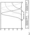
- Figure 1 shows a typical example of a lognormal particle size distribution.
- CMD count median diameter
- GSD geometric standard deviation
- the mass median diameter is almost twice as high as CMD.
- the trap voltage is set to a value which corresponds to cut-off diameter of 50 nm. Penetration through the trap is essentially zero for particles smaller than the cut-off diameter and above it the trap penetration smoothly increases.
- FIG. 2 shows one embodiment of the invented apparatus 1 for particle mass concentration measurement.
- Apparatus 1 comprises passage 2 with inlet 3 and outlet 3 for guiding sample flow Q comprising particles P, P* with a certain particle size distribution through apparatus 1.
- the flow Q through passage 2 can be realized in various ways such as by using a pump, by using chimney effect or by using ion wind.
- fan 5 drives air into inner passage 2* through filter 6. This air is passed next to the means 7, 8 for ionizing the air.
- the means 7, 8 for ionizing the air are realized by a corona discharge unit 7, powered by a high voltage source 8, which is electrically isolated from mains with an isolation transformer 9.
- the ionized air forms the motive fluid flow of ejector 10 placed inside passage 2.
- the ejector generates an underpressure, i.e. pressure lower than ambient pressure, which drives sample flow Q with different size particles P, P* into apparatus 1 vial inlet 3.
- the ionized air and particles are effectively mixed in the mixing zone 11 and thus particles P,P* are charged 12, 12*.
- Free ions 11, which as described previously may also be very fine charged particles, are removed by trapping means 13.
- the trapping means comprises for example an electrostatic precipitator, i.e. a voltage trap, removing small charged particles due to their high electrical mobility in an electrical field.
- the necessary trap voltage for the voltage trap is generated by a power source 14, which is controlled by control means 15 for controlling the trap voltage.
- the trapping means 13 may be connected to the control means 15 which control the distance of the trapping electrodes and the electrical field strength is adjusted by adjusting the electrode separation without necessarily adjusting the electrical voltage across the trap electrodes.
- a flow prior to the diffusion trap is generated by an air pump which is controlled by means for controlling the flow.
- the electrical current carried by particles escaping passage 2 via outlet 4 is measured using means 16, 17 for measuring electrical current carried by charged particles.
- means 16 for measuring the escaping current i.e. the electrical current escaping from apparatus 1 with the particles
- other current measurement techniques such as electrodes or a particle filter collecting at least a fraction of the charged particles may be used as well.
- the measured current is converted to mass concentration value using suitable means 18, which may be situated in apparatus 1 or the conversion may be carried out elsewhere, e.g. by recording the current values and providing the conversion afterwards.
- the trapping means 13 for trapping essentially all free ions 11 and charged particles 12 having particle diameter smaller than trap cut-off diameter D c-o , the cut-off diameter D c-o being the particle diameter above which penetration through the trapping means 13 essentially deviates from zero, are connected to the control means 15 for adjusting the trapping means 13 to adjust the trap cut-off diameter D c-o . It is essential to the present invention that the trapping means 13 are adjusted to cut-off diameter D trap , which is significantly higher than the diameter of the essentially free ions, i.e.
- trapping means 13 remove a significant amount of charged particles from particle flow Q and that the trapping means 13 are adjusted to cut-off diameter D ref , which is about the same as the diameter of the essentially free ions.
- the higher cut-off diameter D trap can be adjusted to a value which facilitates measuring of particle characteristics of interest.
- the cut-off diameter D trap can be adjusted to essentially match the count median diameter of the particles in the particle flow Q.
- apparatus 1 comprises means 18 for converting the electrical current signal to particle mass concentration value.
- Figure 3 illustrates particle distribution curves with count median diameter of 50 nm and 200 nm.
- Figure 3 also illustrates penetration through the particle with cut-off diameters corresponding to the CMD's of distribution curves. Note that the x-axis representing particle size is logarithmic.
- the current measured after the trap is about 50% of the current with cut-off diameter at about 4 nm.
- the cut-off diameter can be changed e.g. by adjusting trap voltage of the voltage trap or by adjusting flow prior to the diffusion trap.
- apparatus 1 comprises means 19 for controlling the control means 15 for adjusting the trapping means 13 on the basis of the output of the means 16,17 for measuring the electrical current carried by said charged particles 12, 12*.
- the trap voltage is adjusted during the measurement.
- the control means 15 for adjusting the trapping means 13 set the trap voltage to a value which ensures the removal of essentially all free ions 11, e.g. the trap voltage is set to reference voltage value V ref which corresponds to particle cut-off diameter D ref of around 4 nm or less.
- the current I ref carried by charged particles 12, 12* is measured using current measurement means 16, 17.
- the means 19 for controlling the control means 15 for adjusting trapping means 13 increase trap voltage to a higher level V trap and the current I trap measured by means for current measurement 16, 17 is smaller than I ref because the higher trap voltage V trap traps not only free ions but also particles from the sample flow Q and thus lowers the measured current.
- This trap voltage V trap is the measuring voltage which is used in actual mass concentration measurements.
- V trap can be controlled so that the particle cut-off diameter D trap is about the same as count median diameter. With such trap voltage the sensitivity of the current/mass conversion to changes of median particle diameter is significantly reduced.
- One or more V trap values can be used. For example alternating V trap to lower and higher than said voltage resulting D trap near the CMD produces also information about the distribution of particle diameter in the particle flow Q. For example the particle diameter distribution is broad if said lower and higher V trap voltages result only a minor change in electrical current I trap compared to a situation where the same change in voltage V trap results a major change in I trap .
- apparatus 1 comprises means 19 for controlling the means 15 for adjusting the trapping means 13 on the basis of the output of the means 16,17 for measuring the electrical current carried by said charged particles 12, 12*.
- the flow is adjusted during the measurement.
- the control means 15 for adjusting the trapping means 13 set the flow to a value which ensures the removal of essentially all free ions 11, e.g. the flow is set to reference flow value Q ref which corresponds to particle cut-off diameter D ref of around 4 nm or less.
- the current I ref carried by charged particles 12, 12* is measured using current measurement means 16, 17.
- the means 19 for controlling the control means 15 for adjusting trapping means 13 increase flow to a higher level Q trap and the current I trap measured by means for current measurement 16, 17 is smaller than I ref because the higher flow Q trap traps not only free ions but also particles from the sample flow Q and thus lowers the measured current.
- This flow Q trap is the measuring flow which is used in actual mass concentration measurements.
- Q trap can be controlled so that the particle cut-off diameter D trap is about the same as count median diameter. With such flow the sensitivity of the current/mass conversion to changes of median particle diameter is significantly reduced.
- One or more Q trap values can be used. For example alternating Q trap to lower and higher than said flow resulting D trap near the CMD produces also information about the distribution of particle diameter in the particle flow Q.
- the particle diameter distribution is broad if said lower and higher Q trap values result only a minor change in electrical current I trap compared to a situation where the same change in flow Q trap results a major change in I trap .
- An ion trap for capturing free ions and smallest particles can be used between the means 7, 8 for electrically charging particles P, P* and the diffusion trap. Said ion trap can be a voltage trap.
- the principles of other embodiments comprising a voltage trap can be implemented with a diffusion trap by replacing voltages V ref , V trap of a voltage trap by flows Q ref , Q trap introduced into the passage 2 prior to the diffusion trap.
- the voltage adjustment and the flow adjustment both have a similar effect of changing the cut-off diameter of the particle trap. Therefore in the following embodiments concerning use of a voltage trap, the voltage trap and voltages can be substituted with a diffusion trap and flows with minor or no changes in operation principle of the apparatus. Thus to avoid unnecessary repetition and for the sake of consistency, the embodiments have been described concerning the voltage trap.
- the measuring voltage V trap is adjusted until S ref is reached.
- the initial value of V trap can be a fixed value, a guess or same as V ref .
- reference electrical current I ref results from reference voltage V ref of a first voltage trap.
- Measuring electrical current I trap results from measuring voltage V trap of a second voltage trap.
- the measuring voltage V trap is adjusted based on ratio S of said electrical currents which are measured with measuring means after each voltage trap.
- the first and second voltage traps voltage traps can be arranged in cascade so that the particle flow Q travels first through the voltage trap having reference voltage and the through the voltage trap having measuring voltage.
- the first and second voltage traps voltage traps can also be arranged in parallel so that the particle flow Q is divided into the two voltage traps.
- the cascade and parallel arrangements allow for continuous monitoring of the current ratio and thus a continuous adjusting is possible.
- a single voltage trap and measurement arrangement can be used if the trap voltage is altered between V ref and V trap in cycles. Therefore the adjustment is carried out in iterating manner and/or the adjusting is repeated one or more times.
- Shape or width of the particle size distribution is the second most important factor after the count median diameter when calculating the particle mass concentration value.
- the trap voltage V trap can be adjusted e.g. in order to reach values 0,3; 0,4; 0,5; 0,6 and 0,7 for S. Also the measurements which were made before the ratio S reached 0,5 can be used.
- the trap voltage V trap can be dynamically adjusted so that it sets and maintains the trap cut-off diameter D trap on a desired position on a curve representing the particle size distribution or the electrical current response of the particle size distribution curve.
- the trap cut-off diameter D trap is adjusted to inflexion point at the curve representing I trap as a function of V trap , where the trap cut-off diameter D trap essentially matches the count median diameter.
- the inflexion point can be found for example by analyzing distortion of a continuously modulated signal.
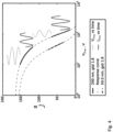
- Figure 4 shows the fundamentals of calculating the inflexion point.
- the trap voltage V trap can be for example sine wave or square wave or some other waveform.
- the response curve is not linear in used voltage range of V trap far from the inflexion point, the resulting I trap (near 150 fA range) is distorted and comprises even harmonics, especially second order harmonics.
- the even harmonics of the distortion go to zero near the inflexion point where the response curve is linear in the used voltage range of V trap and this can be detected for example by monitoring second order harmonics of I ref and correlating it with I trap .
- Another way is to square the voltage signal V trap and find a zero point of correlation between current signal I trap and squared voltage signal. Squaring the voltage signal introduces second order harmonics to the squared signal.
- Second order harmonics do not exist in current signal when operating near the inflexion point and thus the correlation would be zero with squared voltage signal.
- This method allows the acquisition of both the CMD and concentration signals continuously, independent of each other, with higher frequency due to no need for settling time between different voltage levels.
- Another advantage is that the deviation between trap voltages and resulting electrical currents can be used in approximating the width of the particle size distribution, for example by comparing amplitude of I trap and amplitude of V trap .
- Known signal processing methods or transformations such as logarithm conversion or squaring, are preferably used to convert I trap and V trap signals during or before comparison or other analyses.
- An aspect of the invention is a process for particle mass concentration measurement.
- the method comprises guiding sample flow Q comprising particles P, P*, with a count median diameter of CMD and a certain particle size distribution, through a passage 2 and electrically charging particles P, P*.
- the process also comprises measuring the electrical current carried by said charged particles 12, 12*, trapping essentially all free ions 11 and charged particles 12 having particle diameter smaller than trap cut-off diameter D c-o , the cut-off diameter D c-o being the particle diameter above which penetration through the trapping means 13 essentially deviates from zero and adjusting the trapping means 13 to adjust the trap cut-off diameter D c-o based on measured electrical current carried by said charged particles 12, 12*.
- the process further comprises adjusting a trap voltage of the trapping means 13 to a reference cut-off diameter D ref and to a measuring cut-off diameter D trap resulting a reference electrical current I ref and a measuring electrical current I trap carried by said charged particles 12, 12*, and dynamically adjusting the measuring cut-off diameter based on the measurements of the reference electrical current I ref and the measuring electrical current I trap .
- the process further comprises adjusting of the cut-off diameter and alternating the cut-off diameter between a reference cut-off diameter D ref and at least one measuring cut-off diameter D trap resulting a reference electrical current I ref and at least one measuring electrical current I trap carried by said charged particles 12, 12*.
- the process further comprises adjusting a trap voltage of the trapping means 13 to a reference voltage V ref and to a measuring voltage V trap resulting a reference electrical current I ref and a measuring electrical current I trap carried by said charged particles 12, 12*, and dynamically adjusting the measuring voltage based on the measurements of the reference electrical current and the measuring electrical current, wherein the trapping means comprises a voltage trap.
- the process further comprises adjusting a flow of the trapping means 13 to a reference flow Q ref and to a measuring flow Q trap resulting a reference electrical current I ref and a measuring electrical current I trap carried by said charged particles 12, 12*, and dynamically adjusting the measuring flow based on the measurements of the reference electrical current and the measuring electrical current, wherein the trapping means comprises a diffusion trap.
- the process further comprises adjusting cut-off diameter to occasionally deviate the measuring cut-off diameter from the level which results said desired ratio, and estimating the particle size distribution based on derivative of said ratio with respect to the measuring cut-off diameter.
- the process further comprises dynamically adjusting the measuring cut-off diameter for setting and maintaining the trap cut-off diameter D trap on a desired position on a curve representing the particle size distribution.
- the adjusting of the flow of the trapping means 13 comprises adjusting a purge flow of particle free gas prior to the diffusion trap for adjusting the flow.
- the purge flow is introduced to the particle flow Q for increasing the speed of the particles in the flow which then changes the cut-off diameter of the diffusion trap.
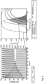
- Figure 5 shows trap voltage and trap current in the left panel for a typical measurement response to a changing particle size.
- the right panel shows the particle number size distribution as well as trap penetration functions for different trap voltages corresponding to the trap voltages in the left panel.
- the shaded areas of the size distribution correspond to measured particles at different trap voltages.
Landscapes
- Health & Medical Sciences (AREA)
- Life Sciences & Earth Sciences (AREA)
- Chemical & Material Sciences (AREA)
- Biochemistry (AREA)
- General Physics & Mathematics (AREA)
- Pathology (AREA)
- Immunology (AREA)
- Analytical Chemistry (AREA)
- Physics & Mathematics (AREA)
- General Health & Medical Sciences (AREA)
- Engineering & Computer Science (AREA)
- Dispersion Chemistry (AREA)
- Biomedical Technology (AREA)
- Molecular Biology (AREA)
- Automation & Control Theory (AREA)
- Other Investigation Or Analysis Of Materials By Electrical Means (AREA)
- Sampling And Sample Adjustment (AREA)
Claims (5)
- Procédé pour la mesure de caractéristiques de particules, comprenant les étapes de :a) guidage d'un flux échantillon (Q) comprenant des particules (P, P*) ayant un diamètre médian de comptage CMD et une certaine distribution des tailles de particules, à travers un passage (2) ;b) charge électrique des particules (P, P*) ;c) mesure du courant électrique porté par lesdites particules chargées (12, 12*) ;d) piégeage de pratiquement la totalité des ions libres (11) et des particules chargées (12) ayant un diamètre de particule inférieur au diamètre de séparation du piège (Dc-o), le diamètre de séparation (Dc-o) étant le diamètre de particule au-delà duquel la pénétration à travers les moyens de piégeage (13) s'écarte essentiellement de zéro ; ete) ajustement des moyens de piégeage (13) pour ajuster le diamètre de séparation du piège (Dc-o) sur la base du courant électrique mesuré porté par lesdites particules chargées (12, 12*),f) ajustement du diamètre de séparation des moyens de piégeage (13) à un diamètre de séparation de référence (Dref) et à un diamètre de séparation de mesure (Dtrap) ayant pour résultat un courant électrique de référence (Iref) et le courant électrique de mesure (Itrap) porté par lesdites particules chargées (12, 12*) ;
dans lequel l'étape f) comprend l'ajustement d'une tension de piège des moyens de piégeage (13) à une tension de référence (Vref) et à une tension de mesure (Vtrap) ayant pour résultat le courant électrique de référence (Iref) et le courant électrique de mesure (Itrap) porté par lesdites particules chargées (12, 12*) ;g) comparaison du courant électrique de référence (Iref) et du courant électrique de mesure (Itrap) ;h) ajustement dynamique par des moyens de commande (15) pour ajuster les moyens de piégeage (13) du diamètre de séparation de mesure (Dtrap), ce qui signifie un changement du diamètre de séparation en continu durant un cycle de mesure, sur la base de la comparaison du courant électrique de référence (Iref) et du courant électrique mesuré (Itrap)dans lequel l'étape h) comprend l'ajustement dynamique de la tension de mesure (Vtrap) sur la base de la comparaison du courant électrique de référence (Iref) et du courant électrique de mesure (Itrap), dans lequel les moyens de piégeage (13) comprennent un piège à tension ; caractérisé en ce quela tension de piège est altérée entre la tension de référence (Vref) et la tension de mesure (Vtrap) de façon que la tension de piège soit commutée entre la tension de référence (Vref) et une ou plusieurs tensions de mesure (Vtrap) toutes les quelques secondes. - Appareil (1) pour la mesure de caractéristiques de particules, l'appareil comprenant :- un passage (2) avec une entrée (3) et une sortie (4) pour guider un flux échantillon (Q) comprenant des particules (P, P*) ayant un diamètre médian de comptage CMD et une certaine distribution des tailles de particules, à travers l'appareil (1) ;- des moyens (7, 8) pour charger électriquement les particules (P, P*) ;- des moyens (16, 17) pour mesurer le courant électrique porté par lesdites particules chargées (12, 12*) ;- des moyens de piégeage (13) pour piéger pratiquement la totalité des ions libres (11) et des particules chargées (12) ayant un diamètre de particule inférieur au diamètre de séparation du piège (Dc-o), le diamètre de séparation (Dc-o) étant le diamètre de particule au-delà duquel la pénétration à travers les moyens de piégeage (13) s'écarte essentiellement de zéro ; et- des moyens de commande (15) pour ajuster les moyens de piégeage (13) pour ajuster le diamètre de séparation du piège (Dc-o) sur la base du courant électrique mesuré porté par lesdites particules chargées (12, 12*),dans lequel les moyens de commande (15) pour ajuster les moyens de piégeage (13) comprennent des moyens (15) pour ajuster le diamètre de séparation à un diamètre de séparation de référence (Dref) et à un diamètre de séparation de mesure (Dtrap) ayant pour résultat un courant électrique de référence (Iref) et un courant électrique de mesure (Itrap) porté par lesdites particules chargées (12, 12*), dans lequel lesdits moyens (15) pour ajuster le diamètre de séparation sont disposés de façon à comparer le courant électrique de référence (Iref) et le courant électrique de mesure (Itrap) et ajuster dynamiquement le diamètre de séparation de mesure (Dtrap), ce qui signifie un changement du diamètre de séparation en continu durant un cycle de mesure, sur la base des mesures et comparaisons du courant électrique de référence (Iref) et du courant électrique de mesure (Itrap), dans lequel les moyens de piégeage (13) comprennent un piège à tension et les moyens de commande (15) pour ajuster le diamètre de séparation sont disposés de façon à ajuster une tension de piège du piège à tension à une tension de référence (Vref) et à une tension de mesure (Vtrap) ayant pour résultat un courant électrique de référence (Iref) et un courant électrique de mesure (Itrap) porté par lesdites particules chargées (12, 12*), dans lequel les moyens de commande (15) pour ajuster la tension de piège sont disposés de façon à ajuster dynamiquement la tension de mesure sur la base des mesures du courant électrique de référence et du courant électrique de mesure ; caractérisé en ce que les moyens de commande (15) sont disposés de façon à altérer la tension de piège entre la tension de référence (Vref) et la tension de mesure (Vtrap) de façon que la tension de piège soit commutée entre la tension de référence (Vref) et une ou plusieurs tensions de mesure (Vtrap) toutes les quelques secondes.
- Appareil (1) selon la revendication 2, caractérisé en ce que les moyens de commande (15) pour ajuster le diamètre de séparation sont disposés de façon à ajuster dynamiquement ledit diamètre de séparation de mesure sur la base du rapport du courant électrique de mesure mesuré au courant électrique de référence mesuré afin d'atteindre et de maintenir un niveau souhaité dudit rapport.
- Appareil (1) selon la revendication 2, caractérisé en ce que les moyens de commande (15) pour ajuster le diamètre de séparation sont disposés de façon à ajuster dynamiquement le diamètre de séparation de mesure pour établir et maintenir le diamètre de séparation du piège (Dtrap) sur une position souhaitée sur une courbe représentant la distribution des tailles de particules.
- Appareil (1) selon la revendication 4, caractérisé en ce que ladite position souhaitée du diamètre de séparation du piège (Dtrap) est au point d'inflexion de la courbe du courant électrique de mesure en fonction du flux de mesure (Qtrap).
Applications Claiming Priority (2)
| Application Number | Priority Date | Filing Date | Title |
|---|---|---|---|
| FI20155783 | 2015-11-02 | ||
| PCT/FI2016/050772 WO2017077190A1 (fr) | 2015-11-02 | 2016-11-02 | Appareil et procédé de mesure de caractéristiques de flux de particules |
Publications (4)
| Publication Number | Publication Date |
|---|---|
| EP3371582A1 EP3371582A1 (fr) | 2018-09-12 |
| EP3371582A4 EP3371582A4 (fr) | 2020-02-12 |
| EP3371582C0 EP3371582C0 (fr) | 2025-05-14 |
| EP3371582B1 true EP3371582B1 (fr) | 2025-05-14 |
Family
ID=58661537
Family Applications (1)
| Application Number | Title | Priority Date | Filing Date |
|---|---|---|---|
| EP16861673.8A Active EP3371582B1 (fr) | 2015-11-02 | 2016-11-02 | Appareil et procédé de mesure de caractéristiques de flux de particules |
Country Status (4)
| Country | Link |
|---|---|
| US (1) | US10760997B2 (fr) |
| EP (1) | EP3371582B1 (fr) |
| ES (1) | ES3036256T3 (fr) |
| WO (1) | WO2017077190A1 (fr) |
Families Citing this family (7)
| Publication number | Priority date | Publication date | Assignee | Title |
|---|---|---|---|---|
| DE102017001438B4 (de) * | 2017-02-15 | 2023-04-27 | Paragon Ag | Partikelsensor |
| KR102024565B1 (ko) * | 2017-04-20 | 2019-09-24 | 엘지전자 주식회사 | 먼지 측정 장치 및 방법 |
| WO2019012185A1 (fr) | 2017-07-14 | 2019-01-17 | Pegasor Oy | Procédé et appareil de surveillance de particules |
| FI128019B (en) * | 2018-05-11 | 2019-08-15 | Pegasor Oy | METHOD AND APPARATUS FOR MEASURING PARTICLES |
| CN109283110A (zh) * | 2018-11-14 | 2019-01-29 | 宋茜 | 一种不同粒径空气负离子浓度测量方法和装置 |
| FI129009B (en) | 2020-02-05 | 2021-05-14 | Dekati Oy | Method and device for monitoring the density of aerosol particles |
| CN111537401B (zh) * | 2020-05-19 | 2023-03-24 | 北京林业大学 | 一种测定颗粒物分形维数的方法 |
Family Cites Families (20)
| Publication number | Priority date | Publication date | Assignee | Title |
|---|---|---|---|---|
| US3449667A (en) * | 1966-05-18 | 1969-06-10 | Gourdine Systems Inc | Electrogasdynamic method and apparatus for detecting the properties of particulate matter entrained in gases |
| US3526828A (en) * | 1967-08-07 | 1970-09-01 | Univ Minnesota | Method and apparatus for measuring particle concentration |
| US20030015045A1 (en) * | 2001-07-23 | 2003-01-23 | Takehito Yoshida | Particle counting method and particle counter |
| DE10242301A1 (de) | 2002-09-12 | 2004-03-18 | Robert Bosch Gmbh | Vorrichtung und Verfahren zur Messung der Konzentration von in einem strömenden Gas vorhandenen Partikeln |
| FI118278B (fi) | 2003-06-24 | 2007-09-14 | Dekati Oy | Menetelmä ja anturilaite hiukkaspäästöjen mittaamiseksi polttomoottorin pakokaasuista |
| JP2008542721A (ja) | 2005-05-23 | 2008-11-27 | ティエスアイ インコーポレイテッド | ナノ粒子接触測定装置 |
| US7728253B2 (en) * | 2005-06-29 | 2010-06-01 | Northeastern University | Nano-particle trap using a microplasma |
| KR100614101B1 (ko) * | 2005-09-15 | 2006-08-22 | 한국과학기술연구원 | 입자 계수기 |
| DE102006041478A1 (de) | 2006-09-05 | 2008-03-06 | Robert Bosch Gmbh | Verfahren zur Ermittlung einer Rußkonzentration im Abgas einer Brennkraftmaschine |
| FI20080182A0 (fi) * | 2008-03-04 | 2008-03-04 | Navaro 245 Oy | Mittausmenetelmä ja -laite |
| JP5657552B2 (ja) | 2008-10-31 | 2015-01-21 | コーニンクレッカ フィリップス エヌ ヴェ | 気流中の荷電浮遊粒子の粒度分布の経時的進展を特徴付けるための装置 |
| US8666679B2 (en) * | 2010-03-31 | 2014-03-04 | The University Of Vermont And State Agriculture College | Micro-fabricated double condenser method and apparatus for the measurement of number-size distribution of airborne nano-particles |
| FIU20100360U0 (fi) | 2010-08-20 | 2010-08-20 | Kauko Janka | Sähköinen hiukkasmittauslaite |
| FI20106395A0 (fi) * | 2010-12-31 | 2010-12-31 | Pegasor Oy | Laitteisto |
| US9574986B2 (en) * | 2012-02-18 | 2017-02-21 | Pegasor Oy | Apparatus and process for producing acknowledged air flow and the use of such apparatus in measuring particle concentration in acknowledged air flow |
| KR200484692Y1 (ko) | 2012-02-18 | 2017-10-18 | 페가소 오와이 | 확인된 공기 흐름을 생성하기 위한 장치 및 방법, 및 확인된 공기 흐름의 입자 농도 측정에서의 그러한 장치의 용도 |
| WO2013132154A1 (fr) | 2012-03-05 | 2013-09-12 | Pegasor Oy | Appareil et processus de mesure de concentration de masse de particules et utilisation d'un appareil de mesure de concentration de masse de particules |
| JP5817929B2 (ja) * | 2012-05-21 | 2015-11-18 | 株式会社島津製作所 | 粒子数測定器 |
| DE202014007548U1 (de) | 2014-09-16 | 2014-12-02 | Pegasor Oy | Vorrichtung zur Spülung einer Partikelmessvorrichtung |
| US10453668B2 (en) * | 2017-02-28 | 2019-10-22 | The Regents Of The University Of California | Spectrometry method and spectrometer device |
-
2016
- 2016-11-02 WO PCT/FI2016/050772 patent/WO2017077190A1/fr not_active Ceased
- 2016-11-02 EP EP16861673.8A patent/EP3371582B1/fr active Active
- 2016-11-02 US US15/772,765 patent/US10760997B2/en active Active
- 2016-11-02 ES ES16861673T patent/ES3036256T3/es active Active
Also Published As
| Publication number | Publication date |
|---|---|
| WO2017077190A1 (fr) | 2017-05-11 |
| EP3371582A1 (fr) | 2018-09-12 |
| ES3036256T3 (en) | 2025-09-18 |
| EP3371582C0 (fr) | 2025-05-14 |
| US20180238777A1 (en) | 2018-08-23 |
| US10760997B2 (en) | 2020-09-01 |
| EP3371582A4 (fr) | 2020-02-12 |
Similar Documents
| Publication | Publication Date | Title |
|---|---|---|
| EP3371582B1 (fr) | Appareil et procédé de mesure de caractéristiques de flux de particules | |
| CN104487817B (zh) | 用于颗粒质量浓度测量的设备和过程以及对用于颗粒质量浓度测量的设备的使用 | |
| US9606038B2 (en) | Particle count measurement device | |
| EP3652519B1 (fr) | Procédé de surveillance de particules | |
| Järvinen et al. | Calibration of the new electrical low pressure impactor (ELPI+) | |
| CN104170190B (zh) | 产生已知气流的装置和过程及使用该装置在已知气流中测量颗粒浓度 | |
| US10502710B2 (en) | Particulate matter measurement apparatus and method | |
| JP2008542721A (ja) | ナノ粒子接触測定装置 | |
| KR101540914B1 (ko) | 공기 흐름 내에서 전기적으로 충전된 공기중 입자들의 크기 분포를 특성화하기 위한 디바이스 | |
| WO2012022843A1 (fr) | Capteur de particules | |
| JP2005502044A (ja) | 粒子分布の特性の測定方法 | |
| JP7575123B2 (ja) | エアロゾル粒子を測定するための方法及び装置 | |
| KR20040070341A (ko) | 차량 입자 분석 방법 및 장치 | |
| US20170138831A1 (en) | Particle charging device and particle classification device using the charging device | |
| KR102024565B1 (ko) | 먼지 측정 장치 및 방법 | |
| JP4863883B2 (ja) | 排ガス混合気内の潤滑油量の測定方法とその装置 | |
| US7131343B2 (en) | Method of measuring density properties of a particle distribution | |
| WO2018149889A1 (fr) | Appareil et procédé de caractérisation de particules | |
| WO2019058115A1 (fr) | Système de spectrométrie | |
| EP3392644A1 (fr) | Appareil et procédé de caractérisation de particule | |
| JP4748476B2 (ja) | 微粒子計測装置 | |
| SU615394A1 (ru) | Способ измерени дисперсного состава порошков | |
| Wei et al. | Penetration calibration and verification for the solid particle counting system with polydisperse and monodisperse particles | |
| KR20260041054A (ko) | 입자 흐름의 특성을 측정하기 위한 방법 및 장치 | |
| Sarangi et al. | Aerosol effective density measurement using scanning mobility particle sizer and quartz crystal microbalance with the estimation of involved uncertainty |
Legal Events
| Date | Code | Title | Description |
|---|---|---|---|
| STAA | Information on the status of an ep patent application or granted ep patent |
Free format text: STATUS: THE INTERNATIONAL PUBLICATION HAS BEEN MADE |
|
| PUAI | Public reference made under article 153(3) epc to a published international application that has entered the european phase |
Free format text: ORIGINAL CODE: 0009012 |
|
| STAA | Information on the status of an ep patent application or granted ep patent |
Free format text: STATUS: REQUEST FOR EXAMINATION WAS MADE |
|
| 17P | Request for examination filed |
Effective date: 20180518 |
|
| AK | Designated contracting states |
Kind code of ref document: A1 Designated state(s): AL AT BE BG CH CY CZ DE DK EE ES FI FR GB GR HR HU IE IS IT LI LT LU LV MC MK MT NL NO PL PT RO RS SE SI SK SM TR |
|
| AX | Request for extension of the european patent |
Extension state: BA ME |
|
| DAV | Request for validation of the european patent (deleted) | ||
| DAX | Request for extension of the european patent (deleted) | ||
| RIC1 | Information provided on ipc code assigned before grant |
Ipc: B03C 9/00 20060101ALI20190926BHEP Ipc: G01N 27/70 20060101AFI20190926BHEP Ipc: G01N 1/22 20060101ALI20190926BHEP Ipc: B03C 3/68 20060101ALI20190926BHEP Ipc: B03C 3/00 20060101ALI20190926BHEP Ipc: G01N 15/06 20060101ALI20190926BHEP Ipc: B03C 7/00 20060101ALI20190926BHEP |
|
| A4 | Supplementary search report drawn up and despatched |
Effective date: 20200114 |
|
| RIC1 | Information provided on ipc code assigned before grant |
Ipc: G01N 1/22 20060101ALI20200108BHEP Ipc: B03C 3/68 20060101ALI20200108BHEP Ipc: B03C 7/00 20060101ALI20200108BHEP Ipc: B03C 9/00 20060101ALI20200108BHEP Ipc: G01N 27/70 20060101AFI20200108BHEP Ipc: B03C 3/00 20060101ALI20200108BHEP Ipc: G01N 15/06 20060101ALI20200108BHEP |
|
| STAA | Information on the status of an ep patent application or granted ep patent |
Free format text: STATUS: EXAMINATION IS IN PROGRESS |
|
| 17Q | First examination report despatched |
Effective date: 20220405 |
|
| GRAP | Despatch of communication of intention to grant a patent |
Free format text: ORIGINAL CODE: EPIDOSNIGR1 |
|
| STAA | Information on the status of an ep patent application or granted ep patent |
Free format text: STATUS: GRANT OF PATENT IS INTENDED |
|
| INTG | Intention to grant announced |
Effective date: 20240626 |
|
| GRAJ | Information related to disapproval of communication of intention to grant by the applicant or resumption of examination proceedings by the epo deleted |
Free format text: ORIGINAL CODE: EPIDOSDIGR1 |
|
| STAA | Information on the status of an ep patent application or granted ep patent |
Free format text: STATUS: EXAMINATION IS IN PROGRESS |
|
| INTC | Intention to grant announced (deleted) | ||
| GRAP | Despatch of communication of intention to grant a patent |
Free format text: ORIGINAL CODE: EPIDOSNIGR1 |
|
| STAA | Information on the status of an ep patent application or granted ep patent |
Free format text: STATUS: GRANT OF PATENT IS INTENDED |
|
| INTG | Intention to grant announced |
Effective date: 20241122 |
|
| GRAS | Grant fee paid |
Free format text: ORIGINAL CODE: EPIDOSNIGR3 |
|
| GRAA | (expected) grant |
Free format text: ORIGINAL CODE: 0009210 |
|
| STAA | Information on the status of an ep patent application or granted ep patent |
Free format text: STATUS: THE PATENT HAS BEEN GRANTED |
|
| AK | Designated contracting states |
Kind code of ref document: B1 Designated state(s): AL AT BE BG CH CY CZ DE DK EE ES FI FR GB GR HR HU IE IS IT LI LT LU LV MC MK MT NL NO PL PT RO RS SE SI SK SM TR |
|
| REG | Reference to a national code |
Ref country code: GB Ref legal event code: FG4D |
|
| REG | Reference to a national code |
Ref country code: CH Ref legal event code: EP |
|
| REG | Reference to a national code |
Ref country code: DE Ref legal event code: R096 Ref document number: 602016092265 Country of ref document: DE |
|
| REG | Reference to a national code |
Ref country code: IE Ref legal event code: FG4D |
|
| U01 | Request for unitary effect filed |
Effective date: 20250611 |
|
| U07 | Unitary effect registered |
Designated state(s): AT BE BG DE DK EE FI FR IT LT LU LV MT NL PT RO SE SI Effective date: 20250617 |
|
| REG | Reference to a national code |
Ref country code: ES Ref legal event code: FG2A Ref document number: 3036256 Country of ref document: ES Kind code of ref document: T3 Effective date: 20250918 |
|
| PG25 | Lapsed in a contracting state [announced via postgrant information from national office to epo] |
Ref country code: GR Free format text: LAPSE BECAUSE OF FAILURE TO SUBMIT A TRANSLATION OF THE DESCRIPTION OR TO PAY THE FEE WITHIN THE PRESCRIBED TIME-LIMIT Effective date: 20250815 Ref country code: NO Free format text: LAPSE BECAUSE OF FAILURE TO SUBMIT A TRANSLATION OF THE DESCRIPTION OR TO PAY THE FEE WITHIN THE PRESCRIBED TIME-LIMIT Effective date: 20250814 |
|
| PG25 | Lapsed in a contracting state [announced via postgrant information from national office to epo] |
Ref country code: PL Free format text: LAPSE BECAUSE OF FAILURE TO SUBMIT A TRANSLATION OF THE DESCRIPTION OR TO PAY THE FEE WITHIN THE PRESCRIBED TIME-LIMIT Effective date: 20250514 |
|
| PG25 | Lapsed in a contracting state [announced via postgrant information from national office to epo] |
Ref country code: HR Free format text: LAPSE BECAUSE OF FAILURE TO SUBMIT A TRANSLATION OF THE DESCRIPTION OR TO PAY THE FEE WITHIN THE PRESCRIBED TIME-LIMIT Effective date: 20250514 |
|
| PG25 | Lapsed in a contracting state [announced via postgrant information from national office to epo] |
Ref country code: RS Free format text: LAPSE BECAUSE OF FAILURE TO SUBMIT A TRANSLATION OF THE DESCRIPTION OR TO PAY THE FEE WITHIN THE PRESCRIBED TIME-LIMIT Effective date: 20250814 |
|
| PG25 | Lapsed in a contracting state [announced via postgrant information from national office to epo] |
Ref country code: IS Free format text: LAPSE BECAUSE OF FAILURE TO SUBMIT A TRANSLATION OF THE DESCRIPTION OR TO PAY THE FEE WITHIN THE PRESCRIBED TIME-LIMIT Effective date: 20250914 |
|
| REG | Reference to a national code |
Ref country code: CH Ref legal event code: U11 Free format text: ST27 STATUS EVENT CODE: U-0-0-U10-U11 (AS PROVIDED BY THE NATIONAL OFFICE) Effective date: 20251201 |
|
| U20 | Renewal fee for the european patent with unitary effect paid |
Year of fee payment: 10 Effective date: 20251104 |
|
| PGFP | Annual fee paid to national office [announced via postgrant information from national office to epo] |
Ref country code: GB Payment date: 20251125 Year of fee payment: 10 |
|
| PG25 | Lapsed in a contracting state [announced via postgrant information from national office to epo] |
Ref country code: SM Free format text: LAPSE BECAUSE OF FAILURE TO SUBMIT A TRANSLATION OF THE DESCRIPTION OR TO PAY THE FEE WITHIN THE PRESCRIBED TIME-LIMIT Effective date: 20250514 |
|
| PGFP | Annual fee paid to national office [announced via postgrant information from national office to epo] |
Ref country code: CH Payment date: 20251201 Year of fee payment: 10 |
|
| PG25 | Lapsed in a contracting state [announced via postgrant information from national office to epo] |
Ref country code: CZ Free format text: LAPSE BECAUSE OF FAILURE TO SUBMIT A TRANSLATION OF THE DESCRIPTION OR TO PAY THE FEE WITHIN THE PRESCRIBED TIME-LIMIT Effective date: 20250514 |
|
| PG25 | Lapsed in a contracting state [announced via postgrant information from national office to epo] |
Ref country code: SK Free format text: LAPSE BECAUSE OF FAILURE TO SUBMIT A TRANSLATION OF THE DESCRIPTION OR TO PAY THE FEE WITHIN THE PRESCRIBED TIME-LIMIT Effective date: 20250514 |
|
| PLBE | No opposition filed within time limit |
Free format text: ORIGINAL CODE: 0009261 |
|
| STAA | Information on the status of an ep patent application or granted ep patent |
Free format text: STATUS: NO OPPOSITION FILED WITHIN TIME LIMIT |
|
| REG | Reference to a national code |
Ref country code: CH Ref legal event code: L10 Free format text: ST27 STATUS EVENT CODE: U-0-0-L10-L00 (AS PROVIDED BY THE NATIONAL OFFICE) Effective date: 20260325 |
|
| PGFP | Annual fee paid to national office [announced via postgrant information from national office to epo] |
Ref country code: ES Payment date: 20260211 Year of fee payment: 10 |
|
| 26N | No opposition filed |
Effective date: 20260217 |