EP3372263A1 - Kanüle für die intraligamentäre anästhesie - Google Patents
Kanüle für die intraligamentäre anästhesie Download PDFInfo
- Publication number
- EP3372263A1 EP3372263A1 EP18153373.8A EP18153373A EP3372263A1 EP 3372263 A1 EP3372263 A1 EP 3372263A1 EP 18153373 A EP18153373 A EP 18153373A EP 3372263 A1 EP3372263 A1 EP 3372263A1
- Authority
- EP
- European Patent Office
- Prior art keywords
- cannula
- distal end
- syringe
- proximal
- tubular body
- Prior art date
- Legal status (The legal status is an assumption and is not a legal conclusion. Google has not performed a legal analysis and makes no representation as to the accuracy of the status listed.)
- Withdrawn
Links
Images


Classifications
-
- A—HUMAN NECESSITIES
- A61—MEDICAL OR VETERINARY SCIENCE; HYGIENE
- A61M—DEVICES FOR INTRODUCING MEDIA INTO, OR ONTO, THE BODY; DEVICES FOR TRANSDUCING BODY MEDIA OR FOR TAKING MEDIA FROM THE BODY; DEVICES FOR PRODUCING OR ENDING SLEEP OR STUPOR
- A61M5/00—Devices for bringing media into the body in a subcutaneous, intra-vascular or intramuscular way; Accessories therefor, e.g. filling or cleaning devices, arm-rests
- A61M5/178—Syringes
- A61M5/31—Details
- A61M5/32—Needles; Details of needles pertaining to their connection with syringe or hub; Accessories for bringing the needle into, or holding the needle on, the body; Devices for protection of needles
- A61M5/3286—Needle tip design, e.g. for improved penetration
-
- A—HUMAN NECESSITIES
- A61—MEDICAL OR VETERINARY SCIENCE; HYGIENE
- A61B—DIAGNOSIS; SURGERY; IDENTIFICATION
- A61B17/00—Surgical instruments, devices or methods
- A61B17/34—Trocars; Puncturing needles
- A61B17/3472—Trocars; Puncturing needles for bones, e.g. intraosseus injections
-
- A—HUMAN NECESSITIES
- A61—MEDICAL OR VETERINARY SCIENCE; HYGIENE
- A61M—DEVICES FOR INTRODUCING MEDIA INTO, OR ONTO, THE BODY; DEVICES FOR TRANSDUCING BODY MEDIA OR FOR TAKING MEDIA FROM THE BODY; DEVICES FOR PRODUCING OR ENDING SLEEP OR STUPOR
- A61M5/00—Devices for bringing media into the body in a subcutaneous, intra-vascular or intramuscular way; Accessories therefor, e.g. filling or cleaning devices, arm-rests
- A61M5/178—Syringes
- A61M5/24—Ampoule syringes, i.e. syringes with needle for use in combination with replaceable ampoules or carpules, e.g. automatic
- A61M5/2455—Ampoule syringes, i.e. syringes with needle for use in combination with replaceable ampoules or carpules, e.g. automatic with sealing means to be broken or opened
- A61M5/2466—Ampoule syringes, i.e. syringes with needle for use in combination with replaceable ampoules or carpules, e.g. automatic with sealing means to be broken or opened by piercing without internal pressure increase
-
- A—HUMAN NECESSITIES
- A61—MEDICAL OR VETERINARY SCIENCE; HYGIENE
- A61M—DEVICES FOR INTRODUCING MEDIA INTO, OR ONTO, THE BODY; DEVICES FOR TRANSDUCING BODY MEDIA OR FOR TAKING MEDIA FROM THE BODY; DEVICES FOR PRODUCING OR ENDING SLEEP OR STUPOR
- A61M5/00—Devices for bringing media into the body in a subcutaneous, intra-vascular or intramuscular way; Accessories therefor, e.g. filling or cleaning devices, arm-rests
- A61M5/178—Syringes
- A61M5/31—Details
- A61M5/3129—Syringe barrels
- A61M5/3134—Syringe barrels characterised by constructional features of the distal end, i.e. end closest to the tip of the needle cannula
-
- A—HUMAN NECESSITIES
- A61—MEDICAL OR VETERINARY SCIENCE; HYGIENE
- A61M—DEVICES FOR INTRODUCING MEDIA INTO, OR ONTO, THE BODY; DEVICES FOR TRANSDUCING BODY MEDIA OR FOR TAKING MEDIA FROM THE BODY; DEVICES FOR PRODUCING OR ENDING SLEEP OR STUPOR
- A61M5/00—Devices for bringing media into the body in a subcutaneous, intra-vascular or intramuscular way; Accessories therefor, e.g. filling or cleaning devices, arm-rests
- A61M5/178—Syringes
- A61M5/31—Details
- A61M5/32—Needles; Details of needles pertaining to their connection with syringe or hub; Accessories for bringing the needle into, or holding the needle on, the body; Devices for protection of needles
- A61M5/329—Needles; Details of needles pertaining to their connection with syringe or hub; Accessories for bringing the needle into, or holding the needle on, the body; Devices for protection of needles characterised by features of the needle shaft
-
- A—HUMAN NECESSITIES
- A61—MEDICAL OR VETERINARY SCIENCE; HYGIENE
- A61B—DIAGNOSIS; SURGERY; IDENTIFICATION
- A61B17/00—Surgical instruments, devices or methods
- A61B17/34—Trocars; Puncturing needles
- A61B17/3417—Details of tips or shafts, e.g. grooves, expandable, bendable; Multiple coaxial sliding cannulas, e.g. for dilating
-
- A—HUMAN NECESSITIES
- A61—MEDICAL OR VETERINARY SCIENCE; HYGIENE
- A61M—DEVICES FOR INTRODUCING MEDIA INTO, OR ONTO, THE BODY; DEVICES FOR TRANSDUCING BODY MEDIA OR FOR TAKING MEDIA FROM THE BODY; DEVICES FOR PRODUCING OR ENDING SLEEP OR STUPOR
- A61M19/00—Local anaesthesia; Hypothermia
Definitions
- the present invention relates to a cannula for intraligamentary anesthesia and a syringe with such a cannula.
- the cannula In intraligamentary anesthesia, the cannula is inserted into the peridontal space or the periodontal space (gap between the neck of the tooth and the gingival margin) so that bone contact is achieved. The anesthetic is then injected into the peridontal cleft of the corresponding tooth root so that the periodontal ligament, including the bony socket, is penetrated by the anesthetic to the apex of the tooth. As a result, the nerve fibers entering the dental pulp are anesthetized in a few seconds. In the case of intraligamentary anesthesia, advantageously little anesthetic is administered per tooth, which may be of particular advantage in cardiovascular risk patients. Since the cannula is sharpened, the puncture pain can be kept relatively low. Regardless, however, a puncture pain always occurs because tissue is injured, regardless of how deep the cannula is inserted into the periodontal cleft. This is disadvantageous especially in patients with syringe anxiety, as each tooth is to be stunned
- the distal end tapers longitudinally from the proximal to the distal end and is rounded and / or free of cut edges, it is possible to insert the cannula into the periodontal space without injuring tissue. This insertion can be performed until bone contact is achieved. Thus, the risk of injury can be minimized and there is no puncture pain.
- the distal end may be spherically rounded.
- the radius of the spherical rounding is half the outer diameter of the tubular body of the cannula.
- the distal end may be ground so that it does not have a bevel angle. Furthermore, the distal end may be ground so that it is semicircular,
- the outer diameter of the cannula may be 0.30 mm or smaller. Outer diameters of 0.300 mm and 0.28 mm are preferred.
- the inside diameter can be 0.133 mm, 0.165 mm or even 0.140 mm. This results in wall thicknesses of 0.0835 mm, 0.0675 mm or 0.08 mm for the outside diameter of 0.3 mm and wall thicknesses of 0.0735 mm, 0.0575 mm and 0.07 mm for the outside diameter of 0.28 mm in front.
- the passage preferably extends coaxially to the longitudinal axis.
- the tubular body preferably has an annular outer contour in cross section, so that the outer diameter is clearly defined.
- an outer contour in cross-section is understood by outer diameter of the diameter of the smallest circular ring in which the outer contour of the tubular body is completely contained.
- the tubular body has over its entire length preferably the same outer contour in cross section.
- the tubular body is designed as a hollow cylinder (in each case preferably with the exception of the proximal and the distal end).
- the tubular body has a constant outer diameter over its entire length.
- the tubular body (with the distal end or optionally without the proximal end) is preferably rotationally symmetrical to the longitudinal axis.
- the tubular body can thus be imaged onto itself by rotation through certain angles.
- the tubular body in cross-section basically have the outer contour of a triangular, a quadrangular or other rotationally symmetrical polygonal surface.
- the outer contour of a circular cross-sectional shape is preferred.
- the tubular body can be rotationally symmetrical to the longitudinal axis.
- the cross section is circular.
- the tubular body thus preferably has, together with its distal end, rotational symmetry or rotational symmetry (imaging on itself at arbitrary angles of rotation about the longitudinal axis).
- the proximal end may preferably be pointed and / or be ground so that it has at least one cutting edge, so that the proximal end is not rotationally symmetrical.
- the cannula may further include a socket.
- the pedestal may serve to connect the cannula to a syringe (eg, a cylindrical ampule syringe).
- the pedestal can with the be glued or welded tubular body.
- the base can be rotationally symmetric or rotationally symmetrical.
- the distal end may be configured such that the radius of the fillet increases toward the distal end.
- the cannula or the tubular body can extend in a straight line. It is also possible that the cannula or the tubular body is bent.
- a syringe is also provided with a cannula according to the invention.
- the syringe can be designed as a cylindrical ampule syringe or cartridge syringe.
- anesthesia method in which a syringe with a cannula according to the invention is inserted into the periodontal gap, the distal end of the cannula facing away from the syringe. In the inserted state, the anesthetic is then administered through the cannula and over the distal end.
- the method may have further steps which are described in connection with the cannula according to the invention and the syringe with the cannula according to the invention.
- the cannula 1 according to the invention comprises a tubular body 2, which has a proximal end 3 and a distal end 4, and a base 5.
- the cannula 1 according to the invention can be used in particular for intraligamentary anesthesia, in which an anesthetic is delivered via the cannula 1 is applied, wherein the cannula 1 may be inserted, for example, in the periodontal gap at the tooth root of the corresponding tooth.
- the cannula 1 according to the invention is on the one hand particularly thin and on the other hand, the distal end 4 in the described embodiment is rounded. Furthermore, the tubular body 2 is integrally formed.
- the body 2 has a passage 6 (which may also be referred to as a bore 6) which extends from a proximal opening 7 at the proximal end of the body 2 to a distal opening 8 at the distal end 4 of the body 2 ,
- the tubular body 2 is rotationally symmetrical to a central axis M, which extends from the proximal to the distal end 3, 4, and has a circular outer contour in a sectional plane perpendicular to the plane in FIG Fig. 2 on.
- the passage 6 has a circular cross-section in this sectional plane and extends coaxially with the central axis M.
- the tubular body 2 has an outer diameter D1 of less than or equal to 0.30 mm. In the embodiment described here, the outer diameter D1 is 0.30 mm.
- the inner diameter D2 of the tubular body 2 and thus the diameter of the passage 6 is 0.133 mm, so that the tubular body 2, which may also be referred to as a hollow needle, has a wall thickness D3 of 0.0835 mm.
- the proximal end 3 of the body 2 is ground, as in Fig. 2 is shown in order to be able to pierce a membrane of a cylindrical ampoule with the proximal end 3, as will be described below.
- the distal end 4 is rounded.
- the distal end is ground in a spherical shape, wherein the radius r of the bevel is preferably half the outer diameter D1 and thus here 0.15 mm.
- the tubular body 2 may be made of steel or stainless steel. Due to the one-piece design and the continuous wall, the required stability is present despite the small outer diameter, even with a length L of the body 2 of e.g. 9 to 15 mm.
- the body 2 is characterized in particular by the fact that it has no further openings except for the two openings 7 and 8. There are thus in particular no lateral outlet openings in the wall, so that the body 2 is free from lateral outlet openings or inlet openings.
- the tubular body 2 has a constant outer diameter over its entire length, except, of course, the rounded distal end 4, which tapers, and the proximal end 3, which is sharpened.
- the diameter of the passage 6 be constant over its entire length, so that the thickness of the wall of the body 2 is constant.
- the base 5 may be made of plastic or metal and is connected to the tubular body 2 e.g. glued or welded.
- a syringe 11 which can be used together with the cannula 1 according to the invention.
- the syringe 11 may be formed, for example, as a cylindrical ampule syringe, which may also be referred to as carpule syringe.
- the syringe 11 comprises a substantially tubular syringe body 12, in which a piston rod 13 is mounted longitudinally displaceable.
- the syringe body 12 comprises a hollow cylindrical main tube 15 with a needle receptacle 16 at the front end and a centering sleeve 17 inserted at the rear end.
- the needle receptacle 16 is screwed into the main tube 15 and glued.
- the centering sleeve 17 is to its stop 18, which rests against the rear end of the main pipe 15, inserted into the main pipe 15.
- a handle cap 19 is screwed and glued at the rear end of the main tube 15, on the rear end of a finger rest 20 is rotatably mounted and secured by a ring 34.
- the ring 34 is screwed onto the rear end of the finger rest 20 and glued.
- a coil spring 21 is arranged, whose ends are connected to the centering sleeve 17 and the handle cap 19, so that the centering sleeve 17 is pressed against the main tube 15.
- the main tube 15 has a lateral loading opening 22 through which the syringe 11 with a schematically in Fig. 5 shown cylinder ampule 23 can be loaded.
- the cylindrical ampoule 23 can be a conventional glass ampoule which is closed at its front end by a membrane layer 24 and at its rear end by a rubber plug 25 (as indicated by the double arrow P1) displaceable in the longitudinal direction of the cylindrical ampoule 23.
- the piston rod 13 of the syringe 11 has at its front end an arrowhead 26 which can be so pushed into the rubber stopper 25 of the inserted cylindrical ampule 23 that the rubber stopper 25 can be moved by the movement of the piston rod 13 in the longitudinal direction.
- the arrowhead 26 can thus be anchored in the rubber stopper 25.
- annular draw ring 27 is attached to the thumb of a user of the syringe 11.
- the previously described parts of the syringe 11 are all made of metal, wherein the piston rod 13 is made of stainless steel and the remaining parts (except for the compression spring 21) are made of chromed brass.
- the syringe body 12 has a length of about 110 mm and the inner diameter of the main tube is about 10 mm.
- the piston rod 13 has a length of about 100 mm.
- the outer and inner diameter of the pull ring 27 is about 32 or 30 mm.
- the piston rod 13 is pulled by means of the thumb portion 27 so back until the arrowhead 26 is completely recessed in a receiving area 30 at the front end of the centering sleeve 17. Further retraction of the piston rod 13 causes the centering sleeve 17 is displaced in the longitudinal direction of the main tube 15 against the spring 21, so that there is sufficient space in the main tube 15 for inserting the cylinder ampoule 23. In this position, the piston rod 13 is held during the insertion of the cylinder ampule 23.
- the piston rod 13 is pushed forward to pierce the arrowhead 26 in the rubber stopper 25. Furthermore, the cannula 1 is pierced through the membrane layer 24 of the cylindrical ampoule 23 by the needle receptacle 16 and the membrane 24. This is easily possible due to the sharpened or sharpened proximal end 3 of the cannula 1. As a result, the syringe 11 is prepared for use.
- the rubber stopper 26 has been shifted over half to the front end of the syringe 1, so that the corresponding fluid that was present in the cylinder ampoule 23, was discharged through the cannula 1 and thus via the distal end 4.
- the fluid may be, for example, an anesthetic.
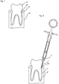
- a tooth 40 is shown together with the gum 41 and the corresponding bone 42 (eg alveolar bone). Between the gum 41 and the tooth 40 is the periodontal gap 43.
- the syringe 11 is positioned so that the proximal end 3, which is rounded, is inserted into the periodontal gap 43. This can for example be done so that bone contact is reached.
- the cannula 1 is inserted into the ligaments of the periodontium, the Sharpey fibers.
- the anesthetic can then be injected via the cannula 1. The anesthetic can penetrate the periodontium including the bony socket to the root tip of the tooth and stun the nerve fibers entering the pulp within a few seconds.
- the distal end 4 is rounded, the previously occurring tissue injury can be avoided in needles with sharpened distal end. It can therefore be avoided injuries and there is no puncture pain.
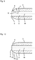
- the distal end 4 of the cannula 1 need not be ground in a spherical shape. It is essential that the distal end 4 tapers in a direction along the central axis from the proximal end 3 to the distal end 4 and is free of cut edges and / or rounded off.
- the radius of curvature increases in this direction, so that the radius of curvature r1 is smaller than the radius of curvature r2.
- the radius of curvature in this direction may also decrease.
- the rounded shape is approximated by one or more sections A1-A3, as in FIG Fig. 10 is shown schematically.
- the sections A1-A3 may, for example, be conical-shell segments.
Landscapes
- Health & Medical Sciences (AREA)
- Life Sciences & Earth Sciences (AREA)
- Animal Behavior & Ethology (AREA)
- Veterinary Medicine (AREA)
- Biomedical Technology (AREA)
- Heart & Thoracic Surgery (AREA)
- Public Health (AREA)
- Engineering & Computer Science (AREA)
- General Health & Medical Sciences (AREA)
- Vascular Medicine (AREA)
- Hematology (AREA)
- Anesthesiology (AREA)
- Surgery (AREA)
- Orthopedic Medicine & Surgery (AREA)
- Pathology (AREA)
- Nuclear Medicine, Radiotherapy & Molecular Imaging (AREA)
- Medical Informatics (AREA)
- Molecular Biology (AREA)
- Infusion, Injection, And Reservoir Apparatuses (AREA)
Abstract
Description
- Die vorliegende Erfindung betrifft eine Kanüle für die intraligamentäre Anästhesie sowie eine Spritze mit einer solchen Kanüle.
- Bei der intraligamentären Anästhesie wird die Kanüle in den Peridontalspalt bzw. den Desmodontalspalt (Spalt zwischen Zahnhals und Zahnfleischsaum) so weit eingeführt, dass Knochenkontakt erreicht wird. Dann wird das Anästhetikum in den Peridontalspalt der entsprechenden Zahnwurzel injiziert, so dass der Zahnhalteapparat einschließlich der knöchernen Alveole bis zur Wurzelspitze des Zahnes mit dem Anästhetikum durchdrungen wird. Dadurch werden in wenigen Sekunden die in das Zahnmark eintretenden Nervenfasern betäubt. Bei der intraligamentären Anästhesie wird vorteilhaft wenig Anästhetikum pro Zahn verabreicht, was besonders bei Herz-Kreislauf-Risikopatienten von Vorteil sein kann. Da die Kanüle spitz angeschliffen ist, kann der Einstichschmerz relativ gering gehalten werden. Unabhängig davon tritt jedoch immer ein Einstichschmerz auf, da Gewebe verletzt wird, unabhängig davon, wie tief die Kanüle in den Desmodontalspalt eingeführt wird. Dies ist gerade bei Patienten mit Spritzenangst nachteilig, da jeder Zahn einzeln zu betäuben ist.
- Ausgehend hiervon ist es daher Aufgabe der Erfindung, eine verbesserte Kanüle für die intraligamentäre Anästhesie bereitzustellen.
- Die Erfindung ist in Anspruch 1 definiert. Vorteilhafte Ausgestaltungen sind in den abhängigen Ansprüchen angegeben.
- Da bei der erfindungsgemäßen Kanüle sich das distale Ende in Längsrichtung vom proximalen zum distalen Ende hin verjüngt sowie abgerundet ist und/oder frei von Schnittkanten ist, ist es möglich, die Kanüle in den Peridontalspalt einzuführen, ohne Gewebe zu verletzen. Dieses Einführen kann so lange durchgeführt werden, bis Knochenkontakt erreicht wird. Somit kann das Verletzungsrisiko minimiert werden und es liegt kein Einstichschmerz vor.
- Insbesondere kann das distale Ende kugelförmig abgerundet sein. Hierbei ist es bevorzugt, dass der Radius der kugelförmigen Abrundung die Hälfte des Außendurchmessers des rohrförmigen Körpers der Kanüle beträgt.
- Das distale Ende kann so angeschliffen sein, dass es keinen Anschliffwinkel aufweist. Ferner kann das distale Ende so angeschliffen sein, dass es halbrund ist,
- Der Außendurchmesser der Kanüle kann 0,30 mm oder kleiner sein. Bevorzugt sind Außendurchmesser von 0,300 mm sowie 0,28 mm. Der Innendurchmesse kann 0,133 mm, 0,165 mm oder auch 0,140 mm betragen. Damit liegen dann Wandstärken von 0,0835 mm, 0,0675 mm oder 0,08 mm beim Außendurchmesser von 0,3 mm und Wandstärken von 0,0735 mm, 0,0575 mm und 0,07 mm beim Außendurchmesser von 0,28 mm vor.
- Der Durchgang erstreckt sich bevorzugt koaxial zur Längsachse.
- Der rohrförmige Körper weist bevorzugt eine kreisringförmige Außenkontur im Querschnitt auf, so dass der Außendurchmesser eindeutig definiert ist. Bei einer anderen Außenkontur im Querschnitt wird unter Außendurchmesser der Durchmesser des kleinsten Kreisringes verstanden, in dem die Außenkontur des rohrförmigen Körpers vollständig enthalten ist.
- Der rohrförmige Körper weist über seine gesamte Länge bevorzugt die gleiche Außenkontur im Querschnitt auf. Insbesondere ist der rohrförmige Körper als Hohlzylinder ausgebildet (jeweils bevorzugt mit Ausnahme des proximalen und des distalen Endes). Insbesondere weist der rohrförmige Körper einen konstanten Außendurchmesser über seine gesamte Länge auf.
- Der rohrförmige Körper (mit dem distalen Ende oder gegebenenfalls ohne das proximale Ende) ist bevorzugt drehsymmetrisch zur Längsachse. Der rohrförmige Körper kann somit durch Drehung um bestimmte Winkel auf sich selbst abgebildet werden. Somit kann der rohrförmige Körper im Querschnitt grundsätzlich die Außenkontur einer dreieckigen, einer viereckigen oder einer sonstigen drehsymmetrischen polygonalen Fläche aufweisen. Bevorzugt ist jedoch die Außenkontur einer kreisförmigen Querschnittsform. Insbesondere kann der rohrförmige Körper rotationssymmetrisch zur Längsachse sein. In diesem Fall ist der Querschnitt kreisringförmig.
- Der rohrförmige Körper weist somit bevorzugt zusammen mit seinem distalen Ende Drehsymmetrie oder Rotationssymmetrie (Abbildung auf sich selbst bei beliebigen Drehwinkeln um die Längsachse) auf. Das proximale Ende kann bevorzugt spitz und/oder so angeschliffen sein, dass es mindestens eine Schneidkante aufweist, so dass das proximale Ende nicht drehsymmetrisch ist.
- Die Kanüle kann ferner einen Sockel aufweisen. Der Sockel kann z.B. dazu dienen, die Kanüle mit einer Spritze (z.B. einer Zylinderampullenspritze) zu verbinden. Der Sockel kann mit dem rohrförmigen Körper verklebt oder verschweißt sein. Ferner kann der Sockel drehsymmetrisch oder rotationssymmetrisch sein.
- Das distale Ende kann so ausgebildet sein, dass der Radius der Abrundung in Richtung hin zum distalen Ende zunimmt.
- Die Kanüle bzw. der rohrförmige Körper kann sich geradlinig erstrecken. Es ist ferner möglich, dass die Kanüle bzw. der rohrförmige Körper gebogen ist.
- Es wird ferner eine Spritze mit einer erfindungsgemäßen Kanüle bereitgestellt. Die Spritze kann als Zylinderampullenspritze oder Karpulenspritze ausgebildet sein.
- Es wird ferner ein Anästhesieverfahren beansprucht, bei dem eine Spritze mit einer erfindungsgemäßen Kanüle in den Peridontalspalt eingeschoben wird, wobei das distale Ende der Kanüle von der Spritze weg weist. Im eingeschobenen Zustand wird dann durch die Kanüle und über das distale Ende das Anästhetikum appliziert.
- Das Verfahren kann weitere Schritte aufweisen, die im Zusammenhang mit der erfindungsgemäßen Kanüle und der Spritze mit der erfindungsgemäßen Kanüle beschrieben sind.
- Es versteht sich, dass die vorstehend genannten und die nachstehend noch zu erläuternden Merkmale nicht nur in den angegebenen Kombinationen, sondern auch in anderen Kombinationen oder in Alleinstellung einsetzbar sind, ohne den Rahmen der vorliegenden Erfindung zu verlassen.
- Nachfolgend wird die Erfindung beispielsweise anhand der beigefügten Zeichnungen, die auch erfindungswesentliche Merkmale offenbaren, noch näher erläutert. Es zeigen:
- Fig. 1
- eine schematische Darstellung einer Ausführungsform der erfindungsgemäßen Kanüle 1:
- Fig. 2
- eine vergrößerte Querschnittsansicht des distalen und proximalen Endes 4.3 des rohrförmigen Körpers 2 der Kanüle 1 von
Fig. 1 ; - Fig. 3
- eine perspektivische Darstellung einer Spritze 11;
- Fig. 4
- eine Schnittansicht der Spritze 11 von
Fig. 3 ; - Fig. 5
- eine schematische Darstellung einer Zylinderampulle 23;
- Fig. 6
- die Spritze 11 gemäß
Fig. 3 und 4 mit der Zylinderampulle23 gemäßFig. 5 und der Kanüle 1 gemäßFig. 1 und 2 ; - Fig. 7
- eine schematische Darstellung eines Zahnes 40;
- Fig. 8
- eine schematische Darstellung des Einführens der mit der Spritze 11 verbundenen Kanüle 1 in den Peridontalspalt 43;
- Fig. 9
- eine Schnittansicht des distalen Endes 4 einer weiteren Ausführungsform der erfindungsgemäßen Kanüle, 1 und
- Fig. 10
- eine Schnittansicht des distalen Endes 4 einer weiteren Ausführungsform der erfindungsgemäßen Kanüle 1.
- Bei der in
Fig. 1 gezeigten Ausführungsform umfasst die erfindungsgemäße Kanüle 1 einen rohrförmigen Körper 2, der ein proximales Ende 3 und ein distales Ende 4 aufweist, und einen Sockel 5. Die erfindungsgemäße Kanüle 1 kann insbesondere bei der intraligamentären Anästhesie eingesetzt werden, bei der ein Anästhetikum über die Kanüle 1 appliziert wird, wobei die Kanüle 1 beispielsweise in dem Periodontalspalt an der Zahnwurzel des entsprechenden Zahnes eingeschoben sein kann. - Um dabei Gewebeverletzungen möglichst zu vermeiden, ist die erfindungsgemäße Kanüle 1 einerseits besonders dünn ausgebildet und ist andererseits das distale Ende 4 bei der beschriebenen Ausführungsform abgerundet. Des Weiteren ist der rohrförmige Körper 2 einstückig ausgebildet.
- Wie insbesondere der Teilschnittansicht des proximalen und distalen Endes 3, 4 in
Fig. 2 entnommen werden kann, weist der Körper 2 einen Durchgang 6 (der auch als Bohrung 6 bezeichnet werden kann) auf, der sich von einer proximalen Öffnung 7 am proximalen Ende des Körpers 2 bis zu einer distalen Öffnung 8 am distalen Ende 4 des Körpers 2 erstreckt. Der rohrförmige Körper 2 ist rotationssymmetrisch zu einer Mittelachse M, die sich vom proximalen bis zum distalen Ende 3, 4 erstreckt, und weist eine kreisförmige Außenkontur in einer Schnittebene senkrecht zur Zeichenebene inFig. 2 auf. Ferner weist der Durchgang 6 in dieser Schnittebene einen kreisförmigen Querschnitt auf und erstreckt sich koaxial zur Mittelachse M. - Der rohrförmige Körper 2 weist einen Außendurchmesser D1 von kleiner oder gleich 0,30 mm auf. Bei der hier beschriebenen Ausführungsform beträgt der Außendurchmesser D1 0,30 mm. Der Innendurchmesser D2 des rohrförmigen Körpers 2 und somit der Durchmesser des Durchganges 6 beträgt 0,133 mm, so dass der rohrförmige Körper 2, der auch als Hohlnadel bezeichnet werden kann, eine Wandstärke D3 von 0,0835 mm aufweist.
- Das proximale Ende 3 des Körpers 2 ist angeschliffen, wie in
Fig. 2 dargestellt ist, um mit dem proximalen Ende 3 eine Membran einer Zylinderampulle durchstoßen zu können, wie nachfolgend noch beschrieben wird. - Das distale Ende 4 ist abgerundet. Bei der hier beschriebenen Ausführungsform ist das distale Ende kugelförmig angeschliffen, wobei der Radius r des Anschliffes bevorzugt die Hälfte des Außendurchmessers D1 und somit hier 0,15 mm beträgt.
- Der rohrförmige Körper 2 kann aus Stahl oder Edelstahl hergestellt sein. Aufgrund der einstückigen Ausbildung und der durchgehenden Wandung liegt trotz des geringen Außendurchmessers die erforderliche Stabilität vor, selbst bei einer Länge L des Körpers 2 von z.B. 9 bis 15 mm. Der Körper 2 zeichnet sich insbesondere dadurch aus, dass er bis auf die beiden Öffnungen 7 und 8 keine weiteren Öffnungen aufweist. Es gibt somit insbesondere keine seitlichen Austrittsöffnungen in der Wandung, so dass der Körper 2 frei von seitlichen Austrittsöffnungen oder Eintrittsöffnungen ist. Insbesondere weist der rohrförmige Körper 2 einen konstanten Außendurchmesser über seine gesamte Länge auf, natürlich mit Ausnahme des abgerundeten distalen Endes 4, das sich verjüngt, und des proximalen Endes 3, das spitz angeschliffen ist. Ferner ist es bevorzugt, dass der Durchmesser des Durchgangs 6 über seine gesamte Länge konstant, so dass auch die Stärke der Wand des Körpers 2 konstant ist.
- Der Sockel 5 kann aus Kunststoff oder Metall bestehen und ist mit dem rohrförmigen Körper 2 z.B. verklebt oder verschweißt.
- In
Fig. 3 und 4 ist eine Spritze 11 gezeigt, die zusammen mit der erfindungsgemäßen Kanüle 1 verwendet werden kann. Die Spritze 11 kann z.B. als Zylinderampullenspritze, die auch als Karpulenspritze bezeichnet werden kann, ausgebildet sein. Die Spritze 11 umfasst einen im Wesentlichen rohrförmig ausgebildeten Spritzenkörper 12, in dem eine Kolbenstange 13 längsverschieblich gelagert ist. - Der Spritzenkörper 12 umfasst ein hohlzylinderförmiges Hauptrohr 15 mit einer Nadelaufnahme 16 am vorderen Ende und einer am hinteren Ende eingesetzten Zentrierhülse 17. Die Nadelaufnahme 16 ist in das Hauptrohr 15 eingeschraubt und verklebt. Die Zentrierhülse 17 ist bis zu ihrem Anschlag 18, der am hinteren Ende des Hauptrohrs 15 anliegt, in das Hauptrohr 15 eingeführt. Ferner ist am hinteren Ende des Hauptrohrs 15 eine Griffkappe 19 aufgeschraubt und verklebt, auf deren hinterem Ende eine Fingerstütze 20 drehbar gelagert und durch einen Ring 34 gesichert ist. Der Ring 34 ist dazu auf dem hinteren Ende der Fingerstütze 20 aufgeschraubt und verklebt. Zwischen der Zentrierhülse 17 und der Griffkappe 19 ist eine Spiralfeder 21 angeordnet, deren Enden mit der Zentrierhülse 17 und der Griffkappe 19 verbunden sind, so dass die Zentrierhülse 17 gegen das Hauptrohr 15 gedrückt wird.
- Das Hauptrohr 15 weist eine seitliche Beladungsöffnung 22 auf, über die die Spritze 11 mit einer schematisch in
Fig. 5 gezeigten Zylinderampulle 23 beladen werden kann. Bei der Zylinderampulle 23 kann es sich um eine herkömmliche Glasampulle handeln, die an ihrem vorderen Ende mit einer Membranschicht 24 und an ihrem hinteren Ende mit einer in der Längsrichtung der Zylinderampulle 23 verschiebbaren (wie durch den Doppelpfeil P1 angedeutet ist) Gummistopfen 25 verschlossen ist. - Die Kolbenstange 13 der Spritze 11 weist an ihrem vorderen Ende eine Pfeilspitze 26 auf, die in den Gummistopfen 25 der eingelegten Zylinderampulle 23 so eingestoßen werden kann, dass der Gummistopfen 25 durch die Bewegung der Kolbenstange 13 in Längsrichtung verschoben werden kann. Die Pfeilspitze 26 kann somit im Gummistopfen 25 verankert werden.
- Am hinteren Ende der Kolbenstange 13 ist ein kreisringförmiger Ziehring 27 für den Daumen eines Benutzers der Spritze 11 befestigt. Die bisher beschriebenen Teile der Spritze 11 sind alle aus Metall hergestellt, wobei die Kolbenstange 13 aus Edelstahl besteht und die restlichen Teile (bis auf die Druckfeder 21) aus verchromtem Messing hergestellt sind. Der Spritzenkörper 12 weist eine Länge von ca. 110 mm auf und der Innendurchmesser des Hauptrohres beträgt ca. 10 mm. Die Kolbenstange 13 weist eine Länge von ca. 100 mm auf. Der Außen- und Innendurchmesser des Ziehrings 27 beträgt ca. 32 oder 30 mm.
- Im Betrieb wird die Kolbenstange 13 mittels des Daumenabschnittes 27 so nach hinten gezogen, bis die Pfeilspitze 26 vollständig in einem Aufnahmebereich 30 am vorderen Ende der Zentrierhülse 17 versenkt ist. Ein weiteres Zurückziehen der Kolbenstange 13 führt dazu, dass die Zentrierhülse 17 in Längsrichtung des Hauptrohres 15 entgegen der Feder 21 verschoben wird, so dass ausreichend Platz im Hauptrohr 15 zum Einlegen der Zylinderampulle 23 vorliegt. In dieser Stellung wird die Kolbenstange 13 während des Einsetzens der Zylinderampulle 23 gehalten. Sobald die Zylinderampulle 23 über die seitliche Beladungsöffnung 22 in das Hauptrohr 15 eingesetzt wurde, kann das Halten der Stellung der Kolbenstange 13 beendet werden, so dass aufgrund der Rückstellkraft der Feder 21 die Zentrierhülse 17 die eingelegte Zylinderampulle 23 gegen die Nadelaufnahme 16 drückt und somit die Zylinderampulle 23 im Hauptrohr 15 fixiert.
- Dann wird die Kolbenstange 13 nach vorne geschoben, um die Pfeilspitze 26 in den Gummistopfen 25 einzustechen. Ferner wird durch die Nadelaufnahme 16 und die Membran 24 die Kanüle 1 durch die Membranschicht 24 der Zylinderampulle 23 gestochen. Dies ist aufgrund des angeschliffenen bzw. angeschärften proximalen Endes 3 der Kanüle 1 leicht möglich. Dadurch ist die Spritze 11 für den Einsatz vorbereitet.
- Bei der in
Fig. 6 gezeigten Stellung ist der Gummistopfen 26 schon über die Hälfte bis zum vorderen Ende der Spritze 1 verschoben, so dass das entsprechende Fluid, das in der Zylinderampulle 23 vorhanden war, über die Kanüle 1 und somit über das distale Ende 4 abgegeben wurde. Bei dem Fluid kann es sich beispielsweise um ein Anästhetikum handeln. - In
Fig. 7 ist in einer schematischen Ansicht ein Zahn 40 zusammen mit dem Zahnfleisch 41 und dem entsprechenden Knochen 42 (z.B. Alveolarknochen) dargestellt. Zwischen dem Zahnfleisch 41 und dem Zahn 40 liegt der Periodontalspalt 43. - Um nun diesen Zahn 40 und den umgebenden Bereich des Zahnes 40 zu betäuben, wird die Spritze 11 so positioniert, dass das proximale Ende 3, das abgerundet ist, in den Peridontalspalt 43 eingeführt ist. Dies kann beispielsweise so erfolgen, dass Knochenkontakt erreicht ist. Damit ist die Kanüle 1 in die Bänder des Zahnhalteapparats, die Sharpey-Fasern, eingeführt. Dort kann dann das Anästhetikum über die Kanüle 1 injiziert werden. Das Anästhetikum kann den Zahnhalteapparat einschließlich der knöchernen Alveole bis zur Wurzelspitze des Zahnes durchdringen und betäubt dort in wenigen Sekunden die in das Zahnmark eintretenden Nervenfasern.
- Da das distale Ende 4 abgerundet ist, kann die bisher immer auftretende Gewebeverletzung bei Kanülen mit angespitztem distalen Ende vermieden werden. Es können also Verletzungen vermieden werden und es tritt auch kein Einstichschmerz auf.
- Das distale Ende 4 der Kanüle 1 muss nicht kugelförmig angeschliffen sein. Wesentlich ist, dass sich das distale Ende 4 in einer Richtung entlang der Mittelachse vom proximalen Ende 3 zum distalen Ende 4 hin verjüngt sowie frei von Schnittkanten und/oder abgerundet ist. Bei der in
Fig. 9 gezeigten Ausführungsform nimmt der Krümmungsradius in dieser Richtung hin zu, so dass der Krümmungsradius r1 kleiner ist als der Krümmungsradius r2. Natürlich kann der Krümmungsradius in dieser Richtung auch abnehmen. - Des Weiteren ist es möglich, dass die abgerundete Form durch einen oder mehrere Abschnitte A1-A3 angenähert ist, wie in
Fig. 10 schematisch dargestellt ist. Bei den Abschnitten A1-A3 kann es sich beispielsweise um Kegelmantelsegmente handeln.
Claims (11)
- Kanüle für die intraligamentäre Anästhesie, wobei die Kanüle (1) einen rohrförmigen Körper (2) mit einem proximalen und einem distalen Ende (3, 4) aufweist,
der Körper (2) eine proximale Öffnung (7) im proximalen Ende (3), eine distale Öffnung (8) im distalen Ende (4) und einen sich durch den Körper (2) erstreckenden Durchgang (6), der beide Öffnungen (7, 8) verbindet, umfasst,
wobei der Körper (2) einstückig ausgebildet ist und der Außendurchmesser (D1) des rohrförmigen Körpers (2) an keiner Stelle größer als 0,30 mm ist
und wobei sich das distale Ende (4) in Längsrichtung vom proximalen zum distalen Ende (3, 4) hin verjüngt sowie abgerundet ist und/oder frei von Schnittkanten ist. - Kanüle nach Anspruch 1, bei der das distale Ende kugelförmig abgerundet ist.
- Kanüle nach Anspruch 2, bei der das distale Ende (4) mit einem Radius abgerundet ist, der der Hälfte des Außendurchmessers des Körpers (2) beträgt.
- Kanüle nach einem der obigen Ansprüche, bei dem das distale Ende mit einem Krümmungsradius abgerundet ist, der in Richtung hin zum distalen Ende (4) zunimmt.
- Kanüle nach einem der obigen Ansprüche, wobei der Körper (2) drehsymmetrisch zur Längsachse oder rotationssymmetrisch zur Längsachse ist.
- Kanüle nach einem der obigen Ansprüche, bei der das proximale Ende (3) angespitzt ist.
- Kanüle nach einem der obigen Ansprüche, bei der der rohrförmige Körper (2) einen konstanten Außendurchmesser über seine gesamte Länge aufweist.
- Kanüle nach einem der obigen Ansprüche, bei der der rohrförmige Körper neben der distalen und der proximalen Öffnung (7, 8) keine weiteren Öffnungen aufweist.
- Kanüle nach einem der obigen Ansprüche, bei der der rohrförmige Körper aus Stahl besteht.
- Spritze mit einer Kanüle nach einem der obigen Ansprüche.
- Spritze nach Anspruch 10, wobei die Spritze als Zylinderampullenspritze ausgebildet ist.
Applications Claiming Priority (1)
| Application Number | Priority Date | Filing Date | Title |
|---|---|---|---|
| DE102017104618.6A DE102017104618A1 (de) | 2017-03-06 | 2017-03-06 | Kanüle für die intraligamentäre Anästhesie |
Publications (1)
| Publication Number | Publication Date |
|---|---|
| EP3372263A1 true EP3372263A1 (de) | 2018-09-12 |
Family
ID=61027526
Family Applications (1)
| Application Number | Title | Priority Date | Filing Date |
|---|---|---|---|
| EP18153373.8A Withdrawn EP3372263A1 (de) | 2017-03-06 | 2018-01-25 | Kanüle für die intraligamentäre anästhesie |
Country Status (4)
| Country | Link |
|---|---|
| US (1) | US20180250477A1 (de) |
| EP (1) | EP3372263A1 (de) |
| CA (1) | CA2997486A1 (de) |
| DE (1) | DE102017104618A1 (de) |
Families Citing this family (2)
| Publication number | Priority date | Publication date | Assignee | Title |
|---|---|---|---|---|
| JP6076469B2 (ja) * | 2012-05-09 | 2017-02-08 | イーオン サージカル リミテッド | 腹腔鏡ポート |
| US11944765B2 (en) * | 2019-11-21 | 2024-04-02 | Bedrosian Global, Llc | Transseptal puncture device and method of use |
Citations (6)
| Publication number | Priority date | Publication date | Assignee | Title |
|---|---|---|---|---|
| AU4346199A (en) * | 1995-02-22 | 1999-10-28 | Mark Timothy Smith | Electronic syringe |
| WO2005079441A2 (en) * | 2004-02-17 | 2005-09-01 | Children's Hospital Medical Center | Injection device for administering a vaccine |
| US20080154217A1 (en) * | 2005-02-03 | 2008-06-26 | Vygon | Puncture Tips And Catheter Tubes |
| US20100106104A1 (en) * | 2008-10-28 | 2010-04-29 | Alain Villette | Injection needle |
| WO2014036009A1 (en) * | 2012-08-27 | 2014-03-06 | Clearside Biomedical, Inc. | Apparatus and methods for drug delivery using microneedles |
| US20150018801A1 (en) * | 2013-07-10 | 2015-01-15 | Sargon Lazarof | Anesthesia applicators/injectors for dental and other applications and methods of use |
Family Cites Families (6)
| Publication number | Priority date | Publication date | Assignee | Title |
|---|---|---|---|---|
| JPH0673530B2 (ja) * | 1987-05-07 | 1994-09-21 | 株式会社 ニッショ− | 歯科用洗浄針 |
| US20040039340A1 (en) * | 2001-12-28 | 2004-02-26 | Becton, Dickinson And Company | Shieldable unit dose medical needle assemblies |
| KR100672875B1 (ko) * | 2004-06-08 | 2007-01-24 | 안강 | 의료용 바늘 |
| US20080097387A1 (en) * | 2006-09-04 | 2008-04-24 | Spector David M | Oral cavity liquid delivery system including pre-angled needle assembly and method for using the same |
| EP2133038A1 (de) * | 2008-06-11 | 2009-12-16 | 3M Innovative Properties Company | Vorrichtung und Verfahren zur Lieferung einer dentalen Zusammensetzung |
| US10010677B2 (en) * | 2014-04-24 | 2018-07-03 | Credence Medsystems, Inc. | System and method for safety syringe |
-
2017
- 2017-03-06 DE DE102017104618.6A patent/DE102017104618A1/de not_active Withdrawn
-
2018
- 2018-01-25 EP EP18153373.8A patent/EP3372263A1/de not_active Withdrawn
- 2018-03-06 US US15/913,867 patent/US20180250477A1/en not_active Abandoned
- 2018-03-06 CA CA2997486A patent/CA2997486A1/en active Pending
Patent Citations (6)
| Publication number | Priority date | Publication date | Assignee | Title |
|---|---|---|---|---|
| AU4346199A (en) * | 1995-02-22 | 1999-10-28 | Mark Timothy Smith | Electronic syringe |
| WO2005079441A2 (en) * | 2004-02-17 | 2005-09-01 | Children's Hospital Medical Center | Injection device for administering a vaccine |
| US20080154217A1 (en) * | 2005-02-03 | 2008-06-26 | Vygon | Puncture Tips And Catheter Tubes |
| US20100106104A1 (en) * | 2008-10-28 | 2010-04-29 | Alain Villette | Injection needle |
| WO2014036009A1 (en) * | 2012-08-27 | 2014-03-06 | Clearside Biomedical, Inc. | Apparatus and methods for drug delivery using microneedles |
| US20150018801A1 (en) * | 2013-07-10 | 2015-01-15 | Sargon Lazarof | Anesthesia applicators/injectors for dental and other applications and methods of use |
Also Published As
| Publication number | Publication date |
|---|---|
| CA2997486A1 (en) | 2018-09-06 |
| DE102017104618A1 (de) | 2018-09-06 |
| US20180250477A1 (en) | 2018-09-06 |
Similar Documents
| Publication | Publication Date | Title |
|---|---|---|
| DE69330374T2 (de) | Injektor und dessen anwendung | |
| EP0679408B1 (de) | Vorrichtung zum Einführen eines Katheters in einen Körperhohlraum | |
| DE3880676T2 (de) | Einspritzvorrichtung zum einpflanzen mehrerer arzneimittelkuegelchen. | |
| DE60202315T2 (de) | Flexible Nadelvorrichtung | |
| DE3783068T2 (de) | Medizinische vorrichtung. | |
| DE69121917T2 (de) | Vorrichtung zum anbringen eines drains | |
| DE10030410C1 (de) | Blutlanzettenvorrichtung zur Entnahme von Blut für Diagnosezwecke | |
| DE3327585C2 (de) | ||
| DE3922406C1 (de) | ||
| DE2265373C2 (de) | Katheteranordnung | |
| DE2043843A1 (de) | Vorrichtung zur Entnahme von Proben von inneren menschlichen und tierischen Organen | |
| EP2062607A1 (de) | Spritze mit Haftbeschichtung im Griffbereich | |
| DE3508013A1 (de) | Kombinationsnadel fuer die axillaere plexus-brachialis-anaesthesie | |
| EP0843536B1 (de) | Operationsinstrument | |
| EP3372263A1 (de) | Kanüle für die intraligamentäre anästhesie | |
| DE102005043805A1 (de) | Zentrierhilfe zum Aufsetzen einer Nadel auf ein Injektionsgerät | |
| DE102008006602A1 (de) | Implantatspritze | |
| EP3530304A1 (de) | Kanüle für intravitreale punktion und injektion | |
| EP1350478B1 (de) | Kanüle zum Applizieren von medizinischen Stoffen | |
| DE102022121987B3 (de) | Medizinisches Instrument | |
| EP0296421B1 (de) | Biopsienadel | |
| DE4109442A1 (de) | Stahlkanuele fuer die spinalanaesthesie | |
| DE1566099B1 (de) | Hypodermatische Nadel | |
| DE29823300U1 (de) | Biopsienadel | |
| DE102018200971A1 (de) | Hohlnadel für ein augenchirurgisches Instrument und eine die Hohlnadel umgebenden Hülle |
Legal Events
| Date | Code | Title | Description |
|---|---|---|---|
| PUAI | Public reference made under article 153(3) epc to a published international application that has entered the european phase |
Free format text: ORIGINAL CODE: 0009012 |
|
| STAA | Information on the status of an ep patent application or granted ep patent |
Free format text: STATUS: THE APPLICATION HAS BEEN PUBLISHED |
|
| AK | Designated contracting states |
Kind code of ref document: A1 Designated state(s): AL AT BE BG CH CY CZ DE DK EE ES FI FR GB GR HR HU IE IS IT LI LT LU LV MC MK MT NL NO PL PT RO RS SE SI SK SM TR |
|
| AX | Request for extension of the european patent |
Extension state: BA ME |
|
| STAA | Information on the status of an ep patent application or granted ep patent |
Free format text: STATUS: REQUEST FOR EXAMINATION WAS MADE |
|
| 17P | Request for examination filed |
Effective date: 20190307 |
|
| RBV | Designated contracting states (corrected) |
Designated state(s): AL AT BE BG CH CY CZ DE DK EE ES FI FR GB GR HR HU IE IS IT LI LT LU LV MC MK MT NL NO PL PT RO RS SE SI SK SM TR |
|
| STAA | Information on the status of an ep patent application or granted ep patent |
Free format text: STATUS: EXAMINATION IS IN PROGRESS |
|
| 17Q | First examination report despatched |
Effective date: 20201029 |
|
| STAA | Information on the status of an ep patent application or granted ep patent |
Free format text: STATUS: THE APPLICATION IS DEEMED TO BE WITHDRAWN |
|
| 18D | Application deemed to be withdrawn |
Effective date: 20230801 |