EP3372543A1 - Niederhalter für in drahtfässer einbringbare drahtcoils - Google Patents
Niederhalter für in drahtfässer einbringbare drahtcoils Download PDFInfo
- Publication number
- EP3372543A1 EP3372543A1 EP18159944.0A EP18159944A EP3372543A1 EP 3372543 A1 EP3372543 A1 EP 3372543A1 EP 18159944 A EP18159944 A EP 18159944A EP 3372543 A1 EP3372543 A1 EP 3372543A1
- Authority
- EP
- European Patent Office
- Prior art keywords
- wire
- holding
- hold
- down device
- elements
- Prior art date
- Legal status (The legal status is an assumption and is not a legal conclusion. Google has not performed a legal analysis and makes no representation as to the accuracy of the status listed.)
- Granted
Links
Images

Classifications
-
- B—PERFORMING OPERATIONS; TRANSPORTING
- B65—CONVEYING; PACKING; STORING; HANDLING THIN OR FILAMENTARY MATERIAL
- B65H—HANDLING THIN OR FILAMENTARY MATERIAL, e.g. SHEETS, WEBS, CABLES
- B65H57/00—Guides for filamentary materials; Supports therefor
- B65H57/18—Guides for filamentary materials; Supports therefor mounted to facilitate unwinding of material from packages
-
- B—PERFORMING OPERATIONS; TRANSPORTING
- B23—MACHINE TOOLS; METAL-WORKING NOT OTHERWISE PROVIDED FOR
- B23K—SOLDERING OR UNSOLDERING; WELDING; CLADDING OR PLATING BY SOLDERING OR WELDING; CUTTING BY APPLYING HEAT LOCALLY, e.g. FLAME CUTTING; WORKING BY LASER BEAM
- B23K9/00—Arc welding or cutting
- B23K9/12—Automatic feeding or moving of electrodes or work for spot or seam welding or cutting
- B23K9/133—Means for feeding electrodes, e.g. drums, rolls, motors
- B23K9/1333—Dereeling means
-
- B—PERFORMING OPERATIONS; TRANSPORTING
- B23—MACHINE TOOLS; METAL-WORKING NOT OTHERWISE PROVIDED FOR
- B23K—SOLDERING OR UNSOLDERING; WELDING; CLADDING OR PLATING BY SOLDERING OR WELDING; CUTTING BY APPLYING HEAT LOCALLY, e.g. FLAME CUTTING; WORKING BY LASER BEAM
- B23K9/00—Arc welding or cutting
- B23K9/16—Arc welding or cutting making use of shielding gas
- B23K9/173—Arc welding or cutting making use of shielding gas and of a consumable electrode
-
- B—PERFORMING OPERATIONS; TRANSPORTING
- B65—CONVEYING; PACKING; STORING; HANDLING THIN OR FILAMENTARY MATERIAL
- B65H—HANDLING THIN OR FILAMENTARY MATERIAL, e.g. SHEETS, WEBS, CABLES
- B65H49/00—Unwinding or paying-out filamentary material; Supporting, storing or transporting packages from which filamentary material is to be withdrawn or paid-out
- B65H49/02—Methods or apparatus in which packages do not rotate
- B65H49/04—Package-supporting devices
- B65H49/06—Package-supporting devices for a single operative package
- B65H49/08—Package-supporting devices for a single operative package enclosing the package
-
- B—PERFORMING OPERATIONS; TRANSPORTING
- B65—CONVEYING; PACKING; STORING; HANDLING THIN OR FILAMENTARY MATERIAL
- B65H—HANDLING THIN OR FILAMENTARY MATERIAL, e.g. SHEETS, WEBS, CABLES
- B65H2701/00—Handled material; Storage means
- B65H2701/30—Handled filamentary material
- B65H2701/36—Wires
Definitions
- the invention relates to a hold-down for insertable in wire barrels wire coils.
- Drahtcoil Under Drahtcoil is understood to be wound into a bundle wire.
- the wire is thus looped wound as an endless wire within the coil.
- Such wire coils are used for example in CO 2 - welding wires, but also in high-strength steel wires, such as spring steel wire.
- a wire end of the wire coil is fed to a processing machine, for example a welding machine. In this case, an automatic removal of the wire from the coil. Usually, in this case, a wire end from the interior of the coil is pulled up.
- the wire coils are for this purpose introduced into so-called wire barrels.
- the wire drums may have round but also other cross-sectional shapes.
- hold-downs are used.
- Such a hold-down is for example in DE 20 2011 108 769 U1 disclosed.
- the hold-down comprises a base element which can be arranged on an upper layer of the wire coil, a guide element arranged above the base element for wire extending from the wire coil and at least one connecting element between the base element and the guide element.
- the guide elements are in this case rigid and carry a designed as a rotatable wire guide guide element. This hold-down is characterized by the rotatable wire guide and thus necessarily existing bearing by a relatively complicated structure. In the robust conditions under which the hold-down are used, they are also prone to failure.
- JP 2007 238 323 A discloses a holding-down device for wire coils with a base element, a guide element arranged above the base element, such as wire running out of the wire coil and at least one connection element between the base element and the guide element.
- the base element is designed as an annular disc, which rests on an end face of the wire coil.
- US 2011 / 0186677A also discloses a hold-down for wire coils having a base member, a guide member disposed above the base member, wire extending from the wire coil, and at least one connecting member between the base member and the guide member.
- the connecting elements are formed by straight lines arranged on the shortest path between the guide element and base element connecting elements.
- the basic element itself consists of two coaxially arranged annular retaining elements which are arranged in a horizontal plane and thus rest on the end face of the wire coil.
- the invention is based on the object to provide a hold-down for insertable into wire barrels wire coil, which is characterized by a simple structure and reliably prevents loops on withdrawal of the wire from Drahtcoil.
- this object is achieved by a hold-down with the features mentioned in claim 1.
- the fact that the at least one connecting element-between the base element and guide element-extends along a helically extending curved path between the base element and the guide element, is advantageously achieved that there is no rigid, but a resilient connection between the base element and guide element. This resilient connection ensures that the running of the wire coil wire is resiliently supported according to its current position by the guide element. An uncontrolled loop formation within the wire coil is thus avoided.
- the base element has at least two annularly arranged holding elements for the connecting elements, which are arranged coaxially with each other, wherein the annular holding elements preferably have a different diameter.
- annularly arranged holding elements which are preferably interconnected by holding webs, allow an already spring-trained basic element, which then carries the spirally extending connecting elements, by means of which the resilient interception of the outgoing wire ultimately its actual position carries.
- the smaller-diameter retaining element has a small distance from the guide element, as the respective larger-diameter holding element complained of.
- an approximately cone-shaped construction of the base element is achieved from the individual annular retaining elements, on the one hand offers a guide for the running wire of the wire coil and on the other hand supports a diameter adjustment of the base member to the guide element.
- the spirally extending connecting elements are preferably connected to the smallest diameter retaining ring and the guide element. This makes it possible to achieve a specific spring characteristic of the hold-down device since the spring characteristics of the hold-down devices can be optimally adjusted to the corresponding wire properties of the wire running away from the wire coil via the difference between the radii of the smallest-diameter holding element and the guide element and the arc length of the connecting elements.
- FIG. 1 shows in plan view a generally designated 10 down device for insertable in wire barrels wire coils.
- the use of the blank holder 10 is based on FIG. 4 then shown in more detail.
- the hold-down 10 has a base element 12, which is formed by three annular holding elements 14, 16 and 18.
- the holding elements 14, 16 and 18 each have a different diameter and are arranged coaxially to an imaginary longitudinal axis 20 of the blank holder 10.
- the holding elements 14, 16, and 18 are interconnected by means of retaining webs 22.
- retaining webs 22 In the example shown, three holding webs 22 and three holding elements 14, 16 and 18 are shown.
- the number of annular retaining elements and the number of retaining webs can vary. It can therefore be provided less or more than three holding elements or holding webs.
- the hold-down device 10 further comprises a guide element 24, which is formed by a closed ring element 26.
- the guide element 24 is connected to the base element 12 via connecting elements 28.
- connecting elements 28 are provided, wherein the number of connecting elements 28 may also be less than or greater than 3.
- the connecting elements 28 extend along a spiral-shaped curved path.
- the connecting elements 28 in this case connect the smallest diameter annular retaining element 18 of the base element 12 with the ring element 26 of the guide element 24.
- FIG. 2 shows hold-down 10 in a side view, wherein like parts FIG. 1 provided with the same reference numerals and are not explained again.
- retaining webs 22 and the connecting elements 28 may be formed integrally with the corresponding progressions.
- All components of the blank holder 10 may be made of a wire, such as steel wire be formed with a diameter of 5 mm.
- a diameter of the holding element 14 is for example 550 mm, a diameter of the holding element 16, for example, 450 mm and a diameter of the holding element 18, for example, 380 mm.
- a diameter of the ring element 26 is for example 210 mm.
- the connecting elements 28 have, for example, an arc length of 230 mm and extend over a radius of 225 mm.
- FIG. 2 It is also clear that the holding elements 14, 16, and 18 have a different distance from the ring element 26. This means that the smaller diameter retaining element 18 has a smaller distance from the ring element 26 than the respective more objectionable larger diameter retaining element 16 and 14. Spaced here is the height position of the holding elements 14, 16, 18 understood.
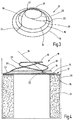
- FIG. 3 is shown in a schematic perspective view again the hold-down 10.
- the approximately domhafte structure of the blank holder 10 is clear.
- the ring member 26 resiliently dodge down or up.
- the wire is thus always supported regardless of its position on the ring member 26 always by an outgoing of the hold-down 10 spring force, so that a loop formation, and thus a possible demolition of the wire is avoided during drainage.
- FIG. 4 is illustrated in a schematic side view of the use of the blank holder 10 in a wire drum 30.
- a wire coil 32 is arranged, which has a plurality of loop-shaped wound wire turns of a wire 34.
- wire drums 30 and therein wire coils 32 for draining wire 34 are well known, so that will not be discussed in detail in the present description.
- the wire 34 is added to a welding machine, for example.
- the hold-down 10 rests with its base element 12 on the upper end face 36 of the wire coil 32.
- the wire 34 is guided by the hold-down 10 and is punctiform on the ring member 26. Since the expiration of the wire 34, this of the wire coil 32 revolves it is important that it is pulled off with a certain tension. When draining the wire 34 from the wire coil 32, it can lead to tension fluctuations, which is compensated by the resilient design of the blank holder 10. As a result, a looping of the wire 34 is avoided.
Landscapes
- Engineering & Computer Science (AREA)
- Physics & Mathematics (AREA)
- Plasma & Fusion (AREA)
- Mechanical Engineering (AREA)
- Media Introduction/Drainage Providing Device (AREA)
- Unwinding Of Filamentary Materials (AREA)
- Wire Processing (AREA)
Abstract
Description
- Die Erfindung betrifft einen Niederhalter für in Drahtfässer einbringbare Drahtcoils.
- Unter Drahtcoil wird ein zu einem Bund aufgewickelter Draht verstanden. Der Draht ist also schleifenförmig als Endlosdraht innerhalb des Coils aufgewickelt. Derartige Drahtcoils werden beispielsweise bei CO2- Schweißdrähten, aber auch bei höherfesten Stahldrähten, beispielsweise Federstahldraht verwendet. Zur Weiterverarbeitung wird ein Drahtende des Drahtcoils einer Verarbeitungsmaschine, beispielsweise einem Schweißautomat zugeführt. Hierbei erfolgt ein automatisches Abführen des Drahtes aus dem Coil. Üblicherweise wird hierbei ein Drahtende vom Inneren des Coils nach oben abgezogen.
- Die Drahtcoils werden hierzu in sogenannte Drahtfässer eingebracht. Die Drahtfässer können runde aber auch andere Querschnittsformen aufweisen.
- Um ein unkontrolliertes Ablaufen des Drahtes aus dem Coil zu verhindern, werden Niederhalter eingesetzt.
- Ein derartiger Niederhalter ist beispielsweise in
DE 20 2011 108 769 U1 offenbart. - Der Niederhalter umfasst ein auf einer oberen Schicht des Drahtcoils anordbares Grundelement, ein oberhalb des Grundelementes angeordnetes Führungselement für aus dem Drahtcoil ablaufenden Draht und wenigstens ein Verbindungselement zwischen dem Grundelement und dem Führungselement. Die Führungselemente sind hierbei starr ausgebildet und tragen ein als drehbare Drahtführung ausgebildetes Führungselement. Dieser Niederhalter zeichnet sich durch die drehbare Drahtführung und dem somit notwendigerweise vorhandenen Lager durch einen relativ komplizierten Aufbau aus. Bei den robusten Bedingungen unter dem die Niederhalter eingesetzt werden, sind diese zudem störanfällig.
-
JP 2007 238 323 A -
US 2011/0186677A offenbart ebenfalls einen Niederhalter für Drahtcoils mit einem Grundelement, einem oberhalb des Grundelementes angeordneten Führungselement, für aus dem Drahtcoil ablaufenden Draht und wenigstens ein Verbindungselement zwischen dem Grundelement und dem Führungselement. Die Verbindungselemente sind von gradlinig auf kürzestem Wege zwischen dem Führungselement und Grundelement angeordneten Verbindungselementen gebildet. Das Grundelement selber besteht aus zwei koaxial zueinander angeordneten ringförmigen Halteelementen die in einer horizontalen Ebene angeordnet sind und somit auf der Stirnfläche des Drahtcoils aufliegen. - Der Erfindung liegt die Aufgabe zu Grunde einen Niederhalter für in Drahtfässer einbringbare Drahtcoils zu schaffen, der sich durch einen einfachen Aufbau auszeichnet und eine Schlaufenbildung beim Abzug des Drahtes vom Drahtcoil sicher verhindert.
- Erfindungsgemäß wird diese Aufgabe durch einen Niederhalter mit den in Anspruch 1 genannten Merkmalen gelöst. Dadurch, dass das wenigstens eine Verbindungselement - zwischen dem Grundelement und Führungselement - entlang einer spiralförmig verlaufenden Kurvenbahn zwischen dem Grundelement und dem Führungselement verläuft, wird vorteilhaft erreicht, dass zwischen dem Grundelement und Führungselement keine starre, sondern eine federnde Verbindung besteht. Diese federnde Verbindung sorgt dafür, dass der von dem Drahtcoil ablaufende Draht entsprechend seiner momentanen Position durch das Führungselement federnd unterstützt wird. Eine unkontrollierte Schlaufenbildung innerhalb des Drahtcoils wird somit vermieden.
- Gemäß der Erfindung ist ferner vorgesehen, dass das Grundelement wenigstens zwei ringförmig angeordnete Halteelemente für die Verbindungselemente aufweist, die koaxial zueinander angeordnet sind, wobei die ringförmigen Halteelemente vorzugsweise einen unterschiedlichen Durchmesser besitzen. Hierdurch wird vorteilhaft möglich, in einfacherweise eine Größenanpassung des Grundelementes und somit auch des Niederhalters an die das Drahtcoil aufnehmenden Drahtfässer zu ermöglichen.
- Ferner ermöglichen die ringförmig angeordneten Halteelemente, die vorzugsweise durch Haltestege untereinander verbunden sind, ein bereits federnd ausgebildetes Grundelement, das dann die spiralförmig verlaufenden Verbindungselemente, mittels der das federnde Abfangen des ablaufenden Drahtes letztendlich seiner tatsächlichen Position erfolgt, trägt.
- Im Sinne der Erfindung ist ferner vorgesehen, dass das durchmesserkleinere Halteelement einen geringen Abstand zum Führungselement aufweist, als das jeweils beanstandete durchmessergrößere Halteelement. Hierdurch wird ein in etwa kegelstupfförmiger Aufbau des Grundelementes aus den einzelnen ringförmigen Halteelementen erreicht, der einerseits eine Führung für den ablaufenden Draht von dem Drahtcoil bietet und andererseits eine Durchmesseranpassung des Grundelementes an das Führungselement unterstützt.
- In bevorzugter Ausgestaltung der Erfindung ist vorgesehen, dass drei um je 120° versetzt verlaufende Verbindungselemente angeordnet sind. Hierdurch wird erreicht, dass durch diese versetzt angeordnete Verbindungselemente, die jeweils spiralförmig zwischen dem Grundelement und dem Führungselement verlaufen, eine besonders gute federnde Führung des ablaufenden Drahtes unabhängig von seiner momentanen Position erzielt wird.
- Die spiralförmig verlaufenden Verbindungselemente sind vorzugsweise mit dem durchmesserkleinsten Haltering und dem Führungselement verbunden. Hierdurch lässt sich eine gezielte Federcharakteristik des Niederhalters erzielen, da über die Differenz der Radien des durchmesserkleinsten Halteelementes und dem Führungselement und der Bogenlänge der Verbindungselemente die Federcharakteristik der Niederhalter optimal auf die entsprechenden Drahteigenschaften des vom Drahtcoil ablaufenden Drahtes abgestellt werden kann.
- Weitere bevorzugte Ausgestaltungen der Erfindung ergeben sich aus den übrigen, in den Unteransprüchen genannten Merkmalen.
- Die Erfindung wird nachfolgend in einem Ausführungsbeispiel anhand der dazugehörigen Zeichnungen näher erläutert. Es zeigen:
- Figur 1
- einen erfindungsgemäßen Niederhalter in Draufsicht ;
- Figur 2
- einen erfindungsgemäßen Niederhalter in einer Seitenansicht;
- Figur 3
- einen erfindungsgemäßen Niederhalter in einer schematischen Perspektivansicht und
- Figur 4
- der Einsatz des erfindungsgemäßen Niederhalters in einem Drahtfass.
- Die
Figur 1 zeigt in Draufsicht einen insgesamt mit 10 bezeichneten Niederhalter für in Drahtfässer einbringbare Drahtcoils. Der Einsatz des Niederhalters 10 wird anhand vonFigur 4 dann noch näher gezeigt. - Der Niederhalter 10 besitzt ein Grundelement 12, das von drei ringförmigen Halteelementen 14, 16 und 18 gebildet ist. Die Halteelemente 14, 16 und 18 besitzen jeweils eine unterschiedlichen Durchmesser und sind koaxial zu einer gedachten Längsachse 20 des Niederhalters 10 angeordnet.
- Die Halteelemente 14, 16, und 18 sind untereinander mittels Haltestegen 22 verbunden. Im gezeigten Beispiel sind drei Haltestege 22 und drei Halteelemente 14, 16 und 18 gezeigt. Nach weiteren, nicht dargestellten Ausführungsbeispielen können die Anzahl der ringförmigen Halteelemente und die Anzahl der Haltestege variieren. Es können also weniger oder auch mehr als drei Haltelemente beziehungsweise Haltestege vorgesehen sein.
- Der Niederhalter 10 umfasst ferner ein Führungselement 24, das von einem geschlossenen Ringelement 26 gebildet ist. Das Führungselement 24 ist mit dem Grundelement 12 über Verbindungselemente 28 verbunden.
- Im gezeigten Beispiel sind drei Verbindungselemente 28 vorgesehen, wobei die Anzahl der Verbindungselemente 28 auch kleiner oder größer als 3 sein kann. Die Verbindungselemente 28 verlaufen entlang einer spiralförmig verlaufenden Kurvenbahn. Die Verbindungselemente 28 verbinden hierbei das durchmesserkleinste ringförmige Halteelement 18 des Grundelementes 12 mit dem Ringelement 26 des Führungselementes 24.
- In
Figur 1 wird deutlich, dass die Haltestege 22 radial zu der Längsachse 20 und die Verbindungselemente 28 exzentrisch zu der Längsachse 20 verlaufen. -
Figur 2 zeigt Niederhalter 10 in einer Seitenansicht, wobei gleiche Teile wie inFigur 1 mit gleichen Bezugszeichen versehen und nicht nochmals erläutert sind. - Es wird deutlich, dass die Haltestege 22 und die Verbindungselemente 28 einstückig mit den entsprechenden Verläufen ausgebildet sein können.
- Sämtliche Bestandteile des Niederhalters 10 können aus einem Draht, beispielsweise Stahldraht mit einem Durchmesser von 5 mm gebildet sein.
- Ein Durchmesser des Halteelementes 14 beträgt beispielsweise 550 mm, ein Durchmesser des Halteelementes 16 beispielsweise 450 mm und ein Durchmesser des Halteelementes 18 beispielsweise 380 mm. Ein Durchmesser des Ringelementes 26 beträgt beispielsweise 210 mm.
- Die Verbindungselemente 28 haben beispielsweise eine Bogenlänge von 230 mm und verlaufen auf einem Radius von 225 mm.
- In
Figur 2 wird auch deutlich, dass die Halteelemente 14, 16, und 18 einen unterschiedlichen Abstand zu dem Ringelement 26 aufweisen. Dies bedeutet, das durchmesserkleinere Halteelement 18 hat einen geringeren Abstand zum Ringelement 26 als das jeweils beanstandende durchmessergrößere Halteelement 16 beziehungsweise 14. Unter Abstand wird hier die Höhenposition der Halteelemente 14, 16, 18 verstanden. - In
Figur 3 ist in einer schematischen Perspektivansicht nochmals der Niederhalter 10 gezeigt. Hierbei wird der in etwa domhafte Aufbau des Niederhalters 10 deutlich. Bei einer punktförmig auf das Ringelement 26 einwirkenden Kraft, durch den - in denFiguren 1 bis 3 nicht gezeigten - ablaufenden Draht von einem Drahtcoil wird das Ringelement 26 federnd nach unten oder oben ausweichen. Der Draht wird somit jederzeit unabhängig von seiner Lage auf dem Ringelement 26 immer durch eine von dem Niederhalter 10 ausgehenden Federkraft unterstützt, so dass eine Schlaufenbildung, und damit ein eventueller Abriss des Drahtes während des Ablaufens vermieden wird. - In
Figur 4 ist in einer schematischen Seitenansicht der Einsatz des Niederhalters 10 in einem Drahtfass 30 verdeutlicht. Innerhalb des Drahtfasses 30 ist ein Drahtcoil 32 angeordnet, das eine Vielzahl von schlaufenförmig aufgewickelten Drahtwindungen eines Drahtes 34 aufweist. - Der Einsatz von Drahtfässern 30 und darin angeordneten Drahtcoils 32 zum Ablaufen von Draht 34 ist allgemein bekannt, so dass hierauf in der vorliegenden Beschreibung nicht näher eingegangen wird. Der Draht 34 wird beispielsweise einem Schweißautomaten zugefügt.
- Der Niederhalter 10 liegt mit seinem Grundelement 12 auf der oberen Stirnfläche 36 des Drahtcoils 32 auf. Der Draht 34 wird durch den Niederhalter 10 geführt und liegt punktförmig an dem Ringelement 26 auf. Da beim Ablaufen des Drahtes 34 sich dieser vom Drahtcoil 32 umlaufend löst, ist wichtig, dass dieser mit einer bestimmten Zugspannung abgezogen wird. Beim Ablaufen des Drahtes 34 vom Drahtcoil 32 kann es zu Zugkraftschwankungen kommen, die durch die federelastische Ausbildung des Niederhalters 10 ausgeglichen wird. Hierdurch wird eine Schlaufenbildung des Drahtes 34 vermieden.
-
- 10
- Niederhalter
- 12
- Grundelement
- 14, 16, 18
- Halteelement
- 20
- Längsachse
- 22
- Haltesteg
- 24
- Führungselement
- 26
- Ringelement
- 28
- Verbindungselement
- 30
- Drahtfass
- 32
- Drahtcoil
- 34
- Draht
- 36
- Stirnfläche
Claims (7)
- Niederhalter (10) für in Drahtfässer (30) einbringbare Drahtcoils (32) mit einem Grundelement (12), einem oberhalb des Grundelementes (12) angeordneten Führungselement (24), für aus dem Drahtcoil (32) ablaufenden Draht (34) und wenigstens ein Verbindungselement (28) zwischen dem Grundelement (12) und dem Führungselement (24), dadurch gekennzeichnet, dass das wenigstens eine Verbindungselement (28) entlang einer spiralförmig verlaufenden Kurvenbahn zwischen dem Grundelement (12) und dem Führungselement (24) verläuft, das Grundelement (12) wenigstens zwei ringförmig angeordnete Halteelemente (14, 16, 18) für die Verbindungselemente (28) aufweist, die koaxial zueinander angeordnet sind, die ringförmigen Halteelemente (14, 16, 18) einen unterschiedlichen Durchmesser besitzen und das durchmessergrößte Halteelement (14) einen größeren Abstand zum Führungselement (24) aufweist als das jeweils benachbarte durchmesserkleinere Halteelement (16, 18).
- Niederhalter (10) nach Anspruch 1, dadurch gekennzeichnet, dass drei um 120° versetzt verlaufende Verbindungselemente (28) angeordnet sind.
- Niederhalter (10) nach einem der vorhergehenden Ansprüche, dadurch gekennzeichnet, dass die ringförmigen Halteelemente (14, 16, 18) untereinander mit Haltestegen (22) verbunden sind.
- Niederhalter (10) nach Anspruch 6, dadurch gekennzeichnet, dass die Haltestege (22) radial verlaufen.
- Niederhalter (10) nach einem der vorhergehenden Ansprüche, dadurch gekennzeichnet, dass die Verbindungselemente (28) den durchmesserkleinsten Haltering (18) mit dem Führungselement (24) verbinden.
- Niederhalter (10) nach einem der vorhergehenden Ansprüche, dadurch gekennzeichnet, dass das Führungselement (24) ein geschlossenes Ringelement (26) ist.
- Niederhalter (10) nach einem der vorhergehenden Ansprüche, dadurch gekennzeichnet, dass das Ringelement (26) einen kleineren Durchmesser besitzt, als das durchmesserkleinste Halteelement (18) des Grundelementes (12).
Priority Applications (1)
| Application Number | Priority Date | Filing Date | Title |
|---|---|---|---|
| PL18159944T PL3372543T3 (pl) | 2017-03-06 | 2018-03-05 | Urządzenie przytrzymujące dla zwoju drutu wprowadzanego do bębnów z drutem |
Applications Claiming Priority (1)
| Application Number | Priority Date | Filing Date | Title |
|---|---|---|---|
| DE102017104586.4A DE102017104586B4 (de) | 2017-03-06 | 2017-03-06 | Niederhalter für in Drahtfässer einbringbare Drahtcoils |
Publications (2)
| Publication Number | Publication Date |
|---|---|
| EP3372543A1 true EP3372543A1 (de) | 2018-09-12 |
| EP3372543B1 EP3372543B1 (de) | 2020-05-13 |
Family
ID=61569099
Family Applications (1)
| Application Number | Title | Priority Date | Filing Date |
|---|---|---|---|
| EP18159944.0A Active EP3372543B1 (de) | 2017-03-06 | 2018-03-05 | Niederhalter für in drahtfässer einbringbare drahtcoils |
Country Status (3)
| Country | Link |
|---|---|
| EP (1) | EP3372543B1 (de) |
| DE (1) | DE102017104586B4 (de) |
| PL (1) | PL3372543T3 (de) |
Families Citing this family (1)
| Publication number | Priority date | Publication date | Assignee | Title |
|---|---|---|---|---|
| DE102023119578A1 (de) | 2023-07-25 | 2025-01-30 | Bayerische Motoren Werke Aktiengesellschaft | Abwickelvorrichtung und Verfahren |
Citations (5)
| Publication number | Priority date | Publication date | Assignee | Title |
|---|---|---|---|---|
| JPS622569U (de) * | 1985-06-18 | 1987-01-09 | ||
| JP2007238323A (ja) * | 2006-03-13 | 2007-09-20 | Komatsu Ltd | 線材ガイド治具 |
| US20110186677A1 (en) * | 2010-01-29 | 2011-08-04 | Michael Carroscia | Wire Dispensing System Including Wire Payoff Structure |
| EP2439005A1 (de) * | 2009-06-03 | 2012-04-11 | Bridgestone Corporation | Drahtabwickel-hilfsvorrichtung |
| CN105290558A (zh) * | 2015-11-25 | 2016-02-03 | 德州恒远焊材有限公司 | 一种梅花形装丝的桶装焊丝用整流罩 |
Family Cites Families (5)
| Publication number | Priority date | Publication date | Assignee | Title |
|---|---|---|---|---|
| GB999212A (en) | 1963-07-20 | 1965-07-21 | F D Sims Ltd | Improved apparatus for handling wire |
| DE2827853C2 (de) | 1978-06-24 | 1983-12-15 | Palitex Project-Company Gmbh, 4150 Krefeld | Ablaufhilfe an Spinn-, Zwirn- und Spulmaschinen für das Über-Kopf-Abziehen eines Fadens von einer Spule |
| JPH05178538A (ja) | 1991-12-27 | 1993-07-20 | Daido Steel Co Ltd | ペイルパック用引出し治具 |
| DE202011108769U1 (de) | 2011-12-07 | 2012-01-24 | Mig Weld Gmbh International | Abspuleinrichtung für Drahtfässer |
| US20150225202A1 (en) | 2014-02-11 | 2015-08-13 | Dw-National Standard-Niles Llc | Ring and container for coiled wire |
-
2017
- 2017-03-06 DE DE102017104586.4A patent/DE102017104586B4/de not_active Expired - Fee Related
-
2018
- 2018-03-05 EP EP18159944.0A patent/EP3372543B1/de active Active
- 2018-03-05 PL PL18159944T patent/PL3372543T3/pl unknown
Patent Citations (5)
| Publication number | Priority date | Publication date | Assignee | Title |
|---|---|---|---|---|
| JPS622569U (de) * | 1985-06-18 | 1987-01-09 | ||
| JP2007238323A (ja) * | 2006-03-13 | 2007-09-20 | Komatsu Ltd | 線材ガイド治具 |
| EP2439005A1 (de) * | 2009-06-03 | 2012-04-11 | Bridgestone Corporation | Drahtabwickel-hilfsvorrichtung |
| US20110186677A1 (en) * | 2010-01-29 | 2011-08-04 | Michael Carroscia | Wire Dispensing System Including Wire Payoff Structure |
| CN105290558A (zh) * | 2015-11-25 | 2016-02-03 | 德州恒远焊材有限公司 | 一种梅花形装丝的桶装焊丝用整流罩 |
Also Published As
| Publication number | Publication date |
|---|---|
| EP3372543B1 (de) | 2020-05-13 |
| DE102017104586A1 (de) | 2018-09-06 |
| DE102017104586B4 (de) | 2022-02-03 |
| PL3372543T3 (pl) | 2020-11-16 |
Similar Documents
| Publication | Publication Date | Title |
|---|---|---|
| DD221984A5 (de) | Fadenliefervorrichtung fuer textilmaschinen | |
| DE112018003629T5 (de) | Filamentwicklungsanlage | |
| DE2711273A1 (de) | Zinken fuer landmaschinen | |
| EP3372543B1 (de) | Niederhalter für in drahtfässer einbringbare drahtcoils | |
| EP3782942B1 (de) | Mehrfachspulenschrank zum aufspulen eines filamentes auf eine transportspule und eine pufferspule hierfür | |
| DE2047214A1 (de) | Verstellbarer Halter für Garnspulen | |
| EP3307933B1 (de) | Flechtmaschine | |
| DE2243718A1 (de) | Verfahren und vorrichtung zum aufwickeln einer vielzahl von draehten auf eine schlauchkarkasse | |
| DE2163976A1 (de) | Verfahren zum verringern der reibung zwischen einem faden und fadenfuehrungsteilen von textilmaschinen | |
| DE2624169B2 (de) | Vorrichtung und verfahren zum kontinuierlichen aufwickeln eines drahtes | |
| DE4240663C1 (de) | Spulenhalter für Garnspulen | |
| DE102012010839B4 (de) | Gewickelte Drahtspule sowie Vorrichtung und Verfahren zur Herstellung der Drahtspule | |
| DE3113528A1 (de) | Vorrichtung zum sz-verseilen mit hilfe einer angetriebenen verseilscheibe und einem rohrfoermigen fuehrungs- und speicherkoerper | |
| DE2919916A1 (de) | Fadenzufuehreinrichtung fuer flachstrickmaschinen | |
| CH671040A5 (de) | ||
| EP4061754B1 (de) | Vorrichtung zum entnehmen von draht von einem drahtpaket | |
| DE102004022246B4 (de) | Vorrichtung zum Eindrehen einer Wendel in Perforationen von Flachteilen | |
| EP2975176A1 (de) | Vorrichtung zum Herstellen von Wendelsieben | |
| DE2631450C2 (de) | Maschine zum Herstellen von Bewehrungskörben für Stahlbeton-Rohre o.dgl | |
| EP2570538B1 (de) | Fadenführer für eine Flachstrickmaschine | |
| EP1416445B1 (de) | Spulenanordnung für Münzprüfer | |
| CH158046A (de) | Verfahren zur Herstellung von vieladrigen Kabeln mit verbesserter Kapazitäts-Symmetrie und Vorrichtung zur Durchführung des Verfahrens. | |
| DE1510811C (de) | Vorrichtung zum störungsfreien Zuführen eines oder mehrerer Fäden zum Fadeneinlaufrohr von Doppeldraht-Zwirnspindeln | |
| DE3039202C2 (de) | ||
| EP3184677B1 (de) | Spindelanordnung und ringspinnmaschine mit der spindelanordnung |
Legal Events
| Date | Code | Title | Description |
|---|---|---|---|
| PUAI | Public reference made under article 153(3) epc to a published international application that has entered the european phase |
Free format text: ORIGINAL CODE: 0009012 |
|
| STAA | Information on the status of an ep patent application or granted ep patent |
Free format text: STATUS: THE APPLICATION HAS BEEN PUBLISHED |
|
| AK | Designated contracting states |
Kind code of ref document: A1 Designated state(s): AL AT BE BG CH CY CZ DE DK EE ES FI FR GB GR HR HU IE IS IT LI LT LU LV MC MK MT NL NO PL PT RO RS SE SI SK SM TR |
|
| AX | Request for extension of the european patent |
Extension state: BA ME |
|
| STAA | Information on the status of an ep patent application or granted ep patent |
Free format text: STATUS: REQUEST FOR EXAMINATION WAS MADE |
|
| 17P | Request for examination filed |
Effective date: 20190123 |
|
| RBV | Designated contracting states (corrected) |
Designated state(s): AL AT BE BG CH CY CZ DE DK EE ES FI FR GB GR HR HU IE IS IT LI LT LU LV MC MK MT NL NO PL PT RO RS SE SI SK SM TR |
|
| GRAP | Despatch of communication of intention to grant a patent |
Free format text: ORIGINAL CODE: EPIDOSNIGR1 |
|
| STAA | Information on the status of an ep patent application or granted ep patent |
Free format text: STATUS: GRANT OF PATENT IS INTENDED |
|
| RIC1 | Information provided on ipc code assigned before grant |
Ipc: B23K 9/133 20060101ALI20191129BHEP Ipc: B23K 9/173 20060101ALI20191129BHEP Ipc: B65H 49/08 20060101AFI20191129BHEP Ipc: B65H 57/18 20060101ALI20191129BHEP |
|
| INTG | Intention to grant announced |
Effective date: 20191220 |
|
| GRAS | Grant fee paid |
Free format text: ORIGINAL CODE: EPIDOSNIGR3 |
|
| GRAA | (expected) grant |
Free format text: ORIGINAL CODE: 0009210 |
|
| STAA | Information on the status of an ep patent application or granted ep patent |
Free format text: STATUS: THE PATENT HAS BEEN GRANTED |
|
| AK | Designated contracting states |
Kind code of ref document: B1 Designated state(s): AL AT BE BG CH CY CZ DE DK EE ES FI FR GB GR HR HU IE IS IT LI LT LU LV MC MK MT NL NO PL PT RO RS SE SI SK SM TR |
|
| REG | Reference to a national code |
Ref country code: GB Ref legal event code: FG4D Free format text: NOT ENGLISH |
|
| REG | Reference to a national code |
Ref country code: CH Ref legal event code: EP |
|
| REG | Reference to a national code |
Ref country code: DE Ref legal event code: R096 Ref document number: 502018001369 Country of ref document: DE |
|
| REG | Reference to a national code |
Ref country code: AT Ref legal event code: REF Ref document number: 1270002 Country of ref document: AT Kind code of ref document: T Effective date: 20200615 |
|
| REG | Reference to a national code |
Ref country code: LT Ref legal event code: MG4D |
|
| REG | Reference to a national code |
Ref country code: NL Ref legal event code: MP Effective date: 20200513 |
|
| PG25 | Lapsed in a contracting state [announced via postgrant information from national office to epo] |
Ref country code: LT Free format text: LAPSE BECAUSE OF FAILURE TO SUBMIT A TRANSLATION OF THE DESCRIPTION OR TO PAY THE FEE WITHIN THE PRESCRIBED TIME-LIMIT Effective date: 20200513 Ref country code: NO Free format text: LAPSE BECAUSE OF FAILURE TO SUBMIT A TRANSLATION OF THE DESCRIPTION OR TO PAY THE FEE WITHIN THE PRESCRIBED TIME-LIMIT Effective date: 20200813 Ref country code: GR Free format text: LAPSE BECAUSE OF FAILURE TO SUBMIT A TRANSLATION OF THE DESCRIPTION OR TO PAY THE FEE WITHIN THE PRESCRIBED TIME-LIMIT Effective date: 20200814 Ref country code: FI Free format text: LAPSE BECAUSE OF FAILURE TO SUBMIT A TRANSLATION OF THE DESCRIPTION OR TO PAY THE FEE WITHIN THE PRESCRIBED TIME-LIMIT Effective date: 20200513 Ref country code: IS Free format text: LAPSE BECAUSE OF FAILURE TO SUBMIT A TRANSLATION OF THE DESCRIPTION OR TO PAY THE FEE WITHIN THE PRESCRIBED TIME-LIMIT Effective date: 20200913 Ref country code: SE Free format text: LAPSE BECAUSE OF FAILURE TO SUBMIT A TRANSLATION OF THE DESCRIPTION OR TO PAY THE FEE WITHIN THE PRESCRIBED TIME-LIMIT Effective date: 20200513 Ref country code: PT Free format text: LAPSE BECAUSE OF FAILURE TO SUBMIT A TRANSLATION OF THE DESCRIPTION OR TO PAY THE FEE WITHIN THE PRESCRIBED TIME-LIMIT Effective date: 20200914 |
|
| PG25 | Lapsed in a contracting state [announced via postgrant information from national office to epo] |
Ref country code: HR Free format text: LAPSE BECAUSE OF FAILURE TO SUBMIT A TRANSLATION OF THE DESCRIPTION OR TO PAY THE FEE WITHIN THE PRESCRIBED TIME-LIMIT Effective date: 20200513 Ref country code: RS Free format text: LAPSE BECAUSE OF FAILURE TO SUBMIT A TRANSLATION OF THE DESCRIPTION OR TO PAY THE FEE WITHIN THE PRESCRIBED TIME-LIMIT Effective date: 20200513 Ref country code: LV Free format text: LAPSE BECAUSE OF FAILURE TO SUBMIT A TRANSLATION OF THE DESCRIPTION OR TO PAY THE FEE WITHIN THE PRESCRIBED TIME-LIMIT Effective date: 20200513 Ref country code: BG Free format text: LAPSE BECAUSE OF FAILURE TO SUBMIT A TRANSLATION OF THE DESCRIPTION OR TO PAY THE FEE WITHIN THE PRESCRIBED TIME-LIMIT Effective date: 20200813 |
|
| PG25 | Lapsed in a contracting state [announced via postgrant information from national office to epo] |
Ref country code: NL Free format text: LAPSE BECAUSE OF FAILURE TO SUBMIT A TRANSLATION OF THE DESCRIPTION OR TO PAY THE FEE WITHIN THE PRESCRIBED TIME-LIMIT Effective date: 20200513 Ref country code: AL Free format text: LAPSE BECAUSE OF FAILURE TO SUBMIT A TRANSLATION OF THE DESCRIPTION OR TO PAY THE FEE WITHIN THE PRESCRIBED TIME-LIMIT Effective date: 20200513 |
|
| PG25 | Lapsed in a contracting state [announced via postgrant information from national office to epo] |
Ref country code: DK Free format text: LAPSE BECAUSE OF FAILURE TO SUBMIT A TRANSLATION OF THE DESCRIPTION OR TO PAY THE FEE WITHIN THE PRESCRIBED TIME-LIMIT Effective date: 20200513 Ref country code: EE Free format text: LAPSE BECAUSE OF FAILURE TO SUBMIT A TRANSLATION OF THE DESCRIPTION OR TO PAY THE FEE WITHIN THE PRESCRIBED TIME-LIMIT Effective date: 20200513 Ref country code: SM Free format text: LAPSE BECAUSE OF FAILURE TO SUBMIT A TRANSLATION OF THE DESCRIPTION OR TO PAY THE FEE WITHIN THE PRESCRIBED TIME-LIMIT Effective date: 20200513 Ref country code: ES Free format text: LAPSE BECAUSE OF FAILURE TO SUBMIT A TRANSLATION OF THE DESCRIPTION OR TO PAY THE FEE WITHIN THE PRESCRIBED TIME-LIMIT Effective date: 20200513 Ref country code: RO Free format text: LAPSE BECAUSE OF FAILURE TO SUBMIT A TRANSLATION OF THE DESCRIPTION OR TO PAY THE FEE WITHIN THE PRESCRIBED TIME-LIMIT Effective date: 20200513 |
|
| REG | Reference to a national code |
Ref country code: DE Ref legal event code: R097 Ref document number: 502018001369 Country of ref document: DE |
|
| PG25 | Lapsed in a contracting state [announced via postgrant information from national office to epo] |
Ref country code: SK Free format text: LAPSE BECAUSE OF FAILURE TO SUBMIT A TRANSLATION OF THE DESCRIPTION OR TO PAY THE FEE WITHIN THE PRESCRIBED TIME-LIMIT Effective date: 20200513 |
|
| PLBE | No opposition filed within time limit |
Free format text: ORIGINAL CODE: 0009261 |
|
| STAA | Information on the status of an ep patent application or granted ep patent |
Free format text: STATUS: NO OPPOSITION FILED WITHIN TIME LIMIT |
|
| 26N | No opposition filed |
Effective date: 20210216 |
|
| PG25 | Lapsed in a contracting state [announced via postgrant information from national office to epo] |
Ref country code: SI Free format text: LAPSE BECAUSE OF FAILURE TO SUBMIT A TRANSLATION OF THE DESCRIPTION OR TO PAY THE FEE WITHIN THE PRESCRIBED TIME-LIMIT Effective date: 20200513 |
|
| PG25 | Lapsed in a contracting state [announced via postgrant information from national office to epo] |
Ref country code: MC Free format text: LAPSE BECAUSE OF FAILURE TO SUBMIT A TRANSLATION OF THE DESCRIPTION OR TO PAY THE FEE WITHIN THE PRESCRIBED TIME-LIMIT Effective date: 20200513 |
|
| REG | Reference to a national code |
Ref country code: CH Ref legal event code: PL |
|
| REG | Reference to a national code |
Ref country code: BE Ref legal event code: MM Effective date: 20210331 |
|
| PG25 | Lapsed in a contracting state [announced via postgrant information from national office to epo] |
Ref country code: CH Free format text: LAPSE BECAUSE OF NON-PAYMENT OF DUE FEES Effective date: 20210331 Ref country code: LI Free format text: LAPSE BECAUSE OF NON-PAYMENT OF DUE FEES Effective date: 20210331 Ref country code: LU Free format text: LAPSE BECAUSE OF NON-PAYMENT OF DUE FEES Effective date: 20210305 Ref country code: IE Free format text: LAPSE BECAUSE OF NON-PAYMENT OF DUE FEES Effective date: 20210305 Ref country code: FR Free format text: LAPSE BECAUSE OF NON-PAYMENT OF DUE FEES Effective date: 20210331 |
|
| PG25 | Lapsed in a contracting state [announced via postgrant information from national office to epo] |
Ref country code: BE Free format text: LAPSE BECAUSE OF NON-PAYMENT OF DUE FEES Effective date: 20210331 |
|
| GBPC | Gb: european patent ceased through non-payment of renewal fee |
Effective date: 20220305 |
|
| PG25 | Lapsed in a contracting state [announced via postgrant information from national office to epo] |
Ref country code: GB Free format text: LAPSE BECAUSE OF NON-PAYMENT OF DUE FEES Effective date: 20220305 |
|
| PGFP | Annual fee paid to national office [announced via postgrant information from national office to epo] |
Ref country code: CZ Payment date: 20230221 Year of fee payment: 6 |
|
| PGFP | Annual fee paid to national office [announced via postgrant information from national office to epo] |
Ref country code: DE Payment date: 20230323 Year of fee payment: 6 |
|
| PG25 | Lapsed in a contracting state [announced via postgrant information from national office to epo] |
Ref country code: CY Free format text: LAPSE BECAUSE OF FAILURE TO SUBMIT A TRANSLATION OF THE DESCRIPTION OR TO PAY THE FEE WITHIN THE PRESCRIBED TIME-LIMIT Effective date: 20200513 |
|
| PG25 | Lapsed in a contracting state [announced via postgrant information from national office to epo] |
Ref country code: HU Free format text: LAPSE BECAUSE OF FAILURE TO SUBMIT A TRANSLATION OF THE DESCRIPTION OR TO PAY THE FEE WITHIN THE PRESCRIBED TIME-LIMIT; INVALID AB INITIO Effective date: 20180305 |
|
| PGFP | Annual fee paid to national office [announced via postgrant information from national office to epo] |
Ref country code: IT Payment date: 20230331 Year of fee payment: 6 |
|
| PG25 | Lapsed in a contracting state [announced via postgrant information from national office to epo] |
Ref country code: MK Free format text: LAPSE BECAUSE OF FAILURE TO SUBMIT A TRANSLATION OF THE DESCRIPTION OR TO PAY THE FEE WITHIN THE PRESCRIBED TIME-LIMIT Effective date: 20200513 |
|
| REG | Reference to a national code |
Ref country code: AT Ref legal event code: MM01 Ref document number: 1270002 Country of ref document: AT Kind code of ref document: T Effective date: 20230305 |
|
| PGFP | Annual fee paid to national office [announced via postgrant information from national office to epo] |
Ref country code: PL Payment date: 20240108 Year of fee payment: 7 |
|
| PG25 | Lapsed in a contracting state [announced via postgrant information from national office to epo] |
Ref country code: TR Free format text: LAPSE BECAUSE OF FAILURE TO SUBMIT A TRANSLATION OF THE DESCRIPTION OR TO PAY THE FEE WITHIN THE PRESCRIBED TIME-LIMIT Effective date: 20200513 |
|
| PG25 | Lapsed in a contracting state [announced via postgrant information from national office to epo] |
Ref country code: AT Free format text: LAPSE BECAUSE OF NON-PAYMENT OF DUE FEES Effective date: 20230305 |
|
| PG25 | Lapsed in a contracting state [announced via postgrant information from national office to epo] |
Ref country code: AT Free format text: LAPSE BECAUSE OF NON-PAYMENT OF DUE FEES Effective date: 20230305 |
|
| PG25 | Lapsed in a contracting state [announced via postgrant information from national office to epo] |
Ref country code: MT Free format text: LAPSE BECAUSE OF FAILURE TO SUBMIT A TRANSLATION OF THE DESCRIPTION OR TO PAY THE FEE WITHIN THE PRESCRIBED TIME-LIMIT Effective date: 20200513 |
|
| REG | Reference to a national code |
Ref country code: DE Ref legal event code: R119 Ref document number: 502018001369 Country of ref document: DE |
|
| PG25 | Lapsed in a contracting state [announced via postgrant information from national office to epo] |
Ref country code: CZ Free format text: LAPSE BECAUSE OF NON-PAYMENT OF DUE FEES Effective date: 20240305 |
|
| PG25 | Lapsed in a contracting state [announced via postgrant information from national office to epo] |
Ref country code: CZ Free format text: LAPSE BECAUSE OF NON-PAYMENT OF DUE FEES Effective date: 20240305 |
|
| PG25 | Lapsed in a contracting state [announced via postgrant information from national office to epo] |
Ref country code: DE Free format text: LAPSE BECAUSE OF NON-PAYMENT OF DUE FEES Effective date: 20241001 |
|
| PG25 | Lapsed in a contracting state [announced via postgrant information from national office to epo] |
Ref country code: DE Free format text: LAPSE BECAUSE OF NON-PAYMENT OF DUE FEES Effective date: 20241001 |
|
| PG25 | Lapsed in a contracting state [announced via postgrant information from national office to epo] |
Ref country code: IT Free format text: LAPSE BECAUSE OF NON-PAYMENT OF DUE FEES Effective date: 20240305 |
|
| PGFP | Annual fee paid to national office [announced via postgrant information from national office to epo] |
Ref country code: AT Payment date: 20260410 Year of fee payment: 5 |