EP3372768B1 - Ferrure pour une porte coulissante - Google Patents
Ferrure pour une porte coulissante Download PDFInfo
- Publication number
- EP3372768B1 EP3372768B1 EP18159444.1A EP18159444A EP3372768B1 EP 3372768 B1 EP3372768 B1 EP 3372768B1 EP 18159444 A EP18159444 A EP 18159444A EP 3372768 B1 EP3372768 B1 EP 3372768B1
- Authority
- EP
- European Patent Office
- Prior art keywords
- roller
- guide
- adjusting
- holding element
- roller support
- Prior art date
- Legal status (The legal status is an assumption and is not a legal conclusion. Google has not performed a legal analysis and makes no representation as to the accuracy of the status listed.)
- Active
Links
Images



Classifications
-
- E—FIXED CONSTRUCTIONS
- E05—LOCKS; KEYS; WINDOW OR DOOR FITTINGS; SAFES
- E05D—HINGES OR SUSPENSION DEVICES FOR DOORS, WINDOWS OR WINGS
- E05D15/00—Suspension arrangements for wings
- E05D15/06—Suspension arrangements for wings for wings sliding horizontally more or less in their own plane
- E05D15/0621—Details, e.g. suspension or supporting guides
- E05D15/0626—Details, e.g. suspension or supporting guides for wings suspended at the top
- E05D15/063—Details, e.g. suspension or supporting guides for wings suspended at the top on wheels with fixed axis
- E05D15/0634—Details, e.g. suspension or supporting guides for wings suspended at the top on wheels with fixed axis with height adjustment
-
- E—FIXED CONSTRUCTIONS
- E05—LOCKS; KEYS; WINDOW OR DOOR FITTINGS; SAFES
- E05Y—INDEXING SCHEME ASSOCIATED WITH SUBCLASSES E05D AND E05F, RELATING TO CONSTRUCTION ELEMENTS, ELECTRIC CONTROL, POWER SUPPLY, POWER SIGNAL OR TRANSMISSION, USER INTERFACES, MOUNTING OR COUPLING, DETAILS, ACCESSORIES, AUXILIARY OPERATIONS NOT OTHERWISE PROVIDED FOR, APPLICATION THEREOF
- E05Y2201/00—Constructional elements; Accessories therefor
- E05Y2201/60—Suspension or transmission members; Accessories therefor
- E05Y2201/622—Suspension or transmission members elements
- E05Y2201/638—Cams; Ramps
-
- E—FIXED CONSTRUCTIONS
- E05—LOCKS; KEYS; WINDOW OR DOOR FITTINGS; SAFES
- E05Y—INDEXING SCHEME ASSOCIATED WITH SUBCLASSES E05D AND E05F, RELATING TO CONSTRUCTION ELEMENTS, ELECTRIC CONTROL, POWER SUPPLY, POWER SIGNAL OR TRANSMISSION, USER INTERFACES, MOUNTING OR COUPLING, DETAILS, ACCESSORIES, AUXILIARY OPERATIONS NOT OTHERWISE PROVIDED FOR, APPLICATION THEREOF
- E05Y2600/00—Mounting or coupling arrangements for elements provided for in this subclass
- E05Y2600/10—Adjustable
- E05Y2600/30—Adjustment motion
- E05Y2600/31—Linear motion
- E05Y2600/312—Horizontal motion
-
- E—FIXED CONSTRUCTIONS
- E05—LOCKS; KEYS; WINDOW OR DOOR FITTINGS; SAFES
- E05Y—INDEXING SCHEME ASSOCIATED WITH SUBCLASSES E05D AND E05F, RELATING TO CONSTRUCTION ELEMENTS, ELECTRIC CONTROL, POWER SUPPLY, POWER SIGNAL OR TRANSMISSION, USER INTERFACES, MOUNTING OR COUPLING, DETAILS, ACCESSORIES, AUXILIARY OPERATIONS NOT OTHERWISE PROVIDED FOR, APPLICATION THEREOF
- E05Y2600/00—Mounting or coupling arrangements for elements provided for in this subclass
- E05Y2600/10—Adjustable
- E05Y2600/30—Adjustment motion
- E05Y2600/31—Linear motion
- E05Y2600/314—Vertical motion
-
- E—FIXED CONSTRUCTIONS
- E05—LOCKS; KEYS; WINDOW OR DOOR FITTINGS; SAFES
- E05Y—INDEXING SCHEME ASSOCIATED WITH SUBCLASSES E05D AND E05F, RELATING TO CONSTRUCTION ELEMENTS, ELECTRIC CONTROL, POWER SUPPLY, POWER SIGNAL OR TRANSMISSION, USER INTERFACES, MOUNTING OR COUPLING, DETAILS, ACCESSORIES, AUXILIARY OPERATIONS NOT OTHERWISE PROVIDED FOR, APPLICATION THEREOF
- E05Y2800/00—Details, accessories and auxiliary operations not otherwise provided for
- E05Y2800/26—Form or shape
- E05Y2800/268—Form or shape cylindrical; disc-shaped; circular
-
- E—FIXED CONSTRUCTIONS
- E05—LOCKS; KEYS; WINDOW OR DOOR FITTINGS; SAFES
- E05Y—INDEXING SCHEME ASSOCIATED WITH SUBCLASSES E05D AND E05F, RELATING TO CONSTRUCTION ELEMENTS, ELECTRIC CONTROL, POWER SUPPLY, POWER SIGNAL OR TRANSMISSION, USER INTERFACES, MOUNTING OR COUPLING, DETAILS, ACCESSORIES, AUXILIARY OPERATIONS NOT OTHERWISE PROVIDED FOR, APPLICATION THEREOF
- E05Y2800/00—Details, accessories and auxiliary operations not otherwise provided for
- E05Y2800/45—Manufacturing
- E05Y2800/46—Injection moulding
Definitions
- the present invention relates to a fitting for a sliding door according to the preamble of claim 1.
- a fitting of the generic type for a sliding door of sliding door furniture is for example from the DE 10244895 A1 known.
- This fitting has a holding element on which the sliding door can be fixed in place.
- a caster carrier is fastened to this holding element in such a way that it can be adjusted in the direction of an axis of rotation of a caster which is rotatably mounted on the caster carrier.
- Numerous components are required to assemble the retaining element with the roller carrier and to guide the roller carrier relative to the retaining element.
- the guide element is designed as a cam which interacts with an adjusting element which is fixedly but rotatably mounted on the holding element and which is designed as an adjusting disk.
- the object of the present invention is to provide a fitting for a sliding door that can be assembled with few components while having a high load-bearing capacity.
- the roller carrier is designed as a die-cast part, in particular a zinc die-cast part.
- roller carrier as a die-cast part offers great design freedom, especially for the integration of various functional elements.
- the at least one first guide element is designed as a cam which is formed in a recess in the bearing surface of the roller carrier, one side edge of the recess forming a guide edge for guiding the adjusting disk.
- a recess is to be understood as a surface formed in the negative z-direction, which is arranged approximately parallel to the bearing surface of the roller carrier at a distance.
- At least one second guide element is designed as a guide web extending in the running direction of the roller, which is molded or formed on at least one inner surface of two walls that are aligned parallel to one another and extend from a support surface of the roller carrier and with a corresponding lateral recess or web as a height adjustment element trained adjusting element cooperates.
- At least one third guide element is formed raised in relation to the bearing surface of the roller carrier for guiding the roller carrier relative to the holding element in a direction parallel to an axis of rotation of the roller.
- This third guide element is preferably designed as a pin which is guided in an elongated hole of the holding element that extends in the direction parallel to the axis of rotation of the roller.
- the holding element preferably made as a stamped and bent part, in particular from sheet steel, allows one or more corresponding elongated holes to be made in a simple manner, while the guide element or elements of the roller carrier in the cast roller carrier made as a die-cast part can be molded on in a simple manner during the manufacture of the roller carrier.
- the walls preferably extend approximately perpendicularly from the bearing surface of the roller carrier.
- guide slots for vertical guidance of a roller housing are preferably formed on the walls.
- a bearing for receiving an adjusting screw is particularly preferably formed on the roller carrier, with which the wedge-shaped height adjustment element can be adjusted, which is held displaceably in the running direction of the roller.
- the roller carrier is designed with at least one hollow chamber.
- the formation of such a hollow chamber serves primarily to stiffen the roller carrier.
- Fig. 1 is denoted by the reference numeral 1 as a whole a variant of a sliding-door furniture, in particular a sliding-door cabinet that can be locked with a plurality of sliding doors 2, 3.
- the sliding doors 2, 3 are guided along a body of the furniture 1 with the aid of two sliding door fittings each.
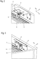
- the sliding door fittings each have rollers 8, as shown in the Figs. 2 and 3 is shown, which are guided in a rail 9 in a running direction x.
- the rail 9 is mounted on a cabinet ceiling 10 of the piece of furniture 1.
- Embodiments of inventive sliding door fittings are in the assembled state in the Figs. 2 and 3 shown.
- Each of the sliding door fittings has a holding element 4, 6 and a roller carrier 5, 7.
- a roller 8 is rotatably mounted on each roller carrier 5, 7.
- the holding elements 4, 6 are designed as stamped and bent parts, preferably made of sheet steel.
- the holding elements 4, 6 are essentially bent in an L-shape, with a first contact surface 41, 61 resting against an inside of the respective sliding door 2, 3 facing the cabinet body and being screwed to this, for example.
- bores 44, 64 are provided in the first contact surface 41, 61, through which the screws can be screwed into the respective sliding door 2, 3.
- a holding surface 42, 62 which is bent over at right angles to the first contact surface 41, 61 is used to fasten the roller carrier 5, 7.
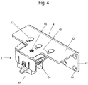
- elongated holes 45 extending in the y direction are made in the holding surface 42, into which guide elements 53, 73, designed as pegs, protrude, which protrude from a support surface 51, 71 of the roller carrier 5, 7 to the holding surface 42, 62 of the holding element 4, 6.
- Fastening elements 17, preferably rivets, are inserted into these pins from the upper side of the holding surface 42, 62 of the holding element 4, 6 facing away from the caster carrier 5, 7, so that the holding element 4, 6 is fixed to the caster carrier 5, 7 in the vertical direction z and is adjustable in direction y parallel to the axis of rotation D of the roller 8.
- an adjusting disk 18 is provided, on the underside of which the roller carrier 5, 7 facing a spiral is formed, which in as a cam trained guide elements 54, 74 engages, the adjustment of the roller carrier 5, 7 are used relative to the holding element 4, 6 in the direction y parallel to an axis of rotation D of the roller 8.
- a side edge of this recess 541, 741 forms a guide edge for guiding the adjusting disk 18.
- a tool holder is formed on its upper side facing away from the roller carrier 5, 7, for example in the form of a polygonal recess, in particular a hexagonal recess, into which a corresponding polygonal tool can be inserted from above through a bore 46 in the holding surface 42 of the holding element 4, 6 is.
- a rotational movement of the spiral in cooperation with the guide elements 54, 74 designed as cams enables the roller carrier 5, 7 to be continuously adjusted relative to the holding element 4, 6 in the y direction parallel to the axis of rotation of the roller 8.
- This so-called depth adjustment can be used on the one hand to align the sliding door 2, 3 relative to the body of the sliding door furniture and to adjust the fitting in relation to the respective installation width of the fitting for the sliding door 2 moving closer to the body.
- the roller 8 is received in a roller housing 11, which is partially received in a wall 521, 522, 721, 722 aligned parallel to one another. These walls 521, 522, 721, 722 extend from the support surface 51, 71 and form a shaft 52, 72 into which the roller housing 11 can be inserted.
- the roller 8 is provided with a central bore through which a shaft 15 serving as the axis of rotation is inserted. Mounted on this shaft 15 are respective bearing rings 16 on both side surfaces of the roller 8.
- the shaft 15 protrudes from a bearing bore 112 of the roller housing 11.
- This bearing bore 112 is formed with an outwardly protruding edge which is formed in a U-shaped recess 56, 76 for vertical guidance of the roller 8 on the walls 521, 522, 721, 722 of the roller carrier 5, 7.
- guide slots 57, 77 for the vertical guidance of the roller housing 11 are preferably formed.
- a bearing 58 for receiving an adjusting screw 14 is formed on the roller carrier 5, 7 in the shaft 52, 72, with which an adjusting element 12 designed as a wedge-shaped height adjustment element in the running direction x of the roller 8 is displaceable in the shaft 52, 72 of the roller carrier 5, 7 adjustable.
- the adjusting element 12 shown here has a receptacle 125 which, in the assembled state, engages around the bearing 58 from below, ie from the open end of the shaft 52, 72.
- Adjacent to the receptacle 125 is a threaded hole in the bearing 58, into which the adjusting screw 14 can be screwed, the height adjusting element 12 being displaced in the running direction x of the roller 8 by turning the adjusting screw 14.
- an inclined surface 122 is provided, which rests against an inclined surface 116 of the roller housing 11.
- the adjustment element 12 designed as a height adjustment element, and the roller housing 11 are positively connected to one another in the area of the inclined surfaces 122, 116.
- a is on the adjustment element 12 T-shaped web 123 is formed, which engages behind a groove 114 in the inclined surface 116 of the roller housing 11.
- guide webs 59 extending in the running direction x of the roller 8 are formed on the inner surfaces of the walls 521, 522, 721, 722 and protrude into corresponding lateral recesses 124 of the adjusting element 12 .
- the longitudinal extent of the recess 741 is correspondingly smaller than the longitudinal extent of the recess 541 (see FIG Fig. 8 and 9 ), since both adjustments of the roller carrier 7 here only have to enable the sliding door 2 to be aligned relative to the body.
- the castor carrier 5, 7 designed as a die-cast part, it has at least one hollow chamber 55, 75.
- such hollow chambers are each formed in the area of the front ends of the roller carrier 5, 7, viewed in direction x.
Landscapes
- Engineering & Computer Science (AREA)
- Mechanical Engineering (AREA)
- Support Devices For Sliding Doors (AREA)
Claims (9)
- Ferrure pour une porte coulissante (2, 3) ou une porte pliante et coulissante, comprenant- un élément de maintien (4, 6), sur lequel la porte coulissante (2, 3) peut être fixée,- un support de galet de roulement (5, 7) retenu par l'élément de maintien (4, 6) et sur lequel au moins un galet de roulement (8) est supporté avec possibilité de rotation,- le support de galet de roulement (5, 7) pouvant être déplacé par rapport à l'élément de maintien (4, 6),- sur lequel au moins un premier et/ou un deuxième élément de guidage (54, 59, 74, 79) est formé d'un seul tenant pour guider au moins un élément d'ajustement (12, 18) pour l'ajustement du galet de roulement par rapport à l'élément de maintien dans une direction parallèle (y) et/ou verticale (z) par rapport à l'axe de rotation (D) du galet de roulement,- dans lequel au moins un premier élément de guidage (54, 74) est conformé comme une came qui coopère avec un élément d'ajustement (18) formé sur l'élément de maintien (4, 6) comme un disque d'ajustement stationnaire mais capable de rotation,caractérisée en ce que- le support de galet de roulement (5, 7) est réalisé comme une pièce coulée sous pression,- les premiers éléments de guidage (54, 74) conformés comme des cames étant formés dans un creux (541, 741) dans la surface d'appui (51, 71) du support de galet de roulement (5, 7), un bord latéral du creux (541, 741) formant un bord de guidage pour le guidage du disque d'ajustement (18).
- Ferrure selon la revendication 1, caractérisée en ce qu'au moins un deuxième élément de guidage (59, 79) est formé comme une barrette de guidage qui s'étend dans le sens de roulement (x) du galet de roulement (8) et qui est formée sur ou à partir d'au moins une face intérieure de deux parois (521, 522, 721, 722) parallèles l'une à l'autre qui s'étendent à partir d'une surface d'appui (51, 71) du support de galet de roulement (5, 7), et qui coopère avec un creux ou une barrette (124) correspondante formée sur le côté d'un élément d'ajustement (12) conçu comme un élément d'ajustement en hauteur.
- Ferrure selon l'une des revendications précédentes, caractérisée en ce qu'au moins un troisième élément de guidage (53, 55, 73, 75) en saillie par rapport à la surface d'appui (51, 71) du support de galet de roulement (5, 7) est formé pour guider le support de galet de roulement (5, 7) par rapport à l'élément de maintien (4, 6) dans une direction (y) parallèle à un axe de rotation (D) du galet de roulement (8).
- Ferrure selon la revendication 3, caractérisée en ce qu'au moins un des troisièmes éléments de guidage (53, 73) est conformé comme un goujon qui est guidé dans un trou oblong (45, 65) de l'élément de maintien (4, 6) orienté dans la direction (y) parallèlement à l'axe de rotation (D) du galet de roulement (8).
- Ferrure selon l'une des revendications 2 à 4, caractérisée en ce que sont formées sur les parois (521, 522, 721, 722), pour le guidage vertical d'une cage de galet (11), des fentes de guidage (57, 77) dans lesquelles dépassent des barrettes de guidage (113) de la cage de galet (11).
- Ferrure selon l'une des revendications 2 à 5, caractérisée en ce qu'est formé sur le support de galet de roulement (5, 7) un palier (58) destiné à recevoir une vis d'ajustement (14) avec laquelle l'élément d'ajustement (12) conçu comme un élément d'ajustement de la hauteur et de préférence en forme de coin peut être déplacé en translation contre une surface oblique de la cage de galet (11) dans le sens de roulement (x) du galet de roulement (8).
- Ferrure selon l'une des revendications précédentes, caractérisée en ce que le support de galet de roulement (5, 7) est muni d'au moins un compartiment creux.
- Ferrure selon l'une des revendications précédentes, caractérisée en ce que l'élément de maintien (4, 6) est une pièce découpée à l'emporte-pièce et pliée, en particulier en tôle d'acier.
- Ferrure selon l'une des revendications précédentes, caractérisée en ce que le support de galet de roulement et/ou l'élément de maintien est/sont en forme de L.
Applications Claiming Priority (1)
| Application Number | Priority Date | Filing Date | Title |
|---|---|---|---|
| DE102017104694.1A DE102017104694A1 (de) | 2017-03-07 | 2017-03-07 | Beschlag für eine Schiebetür |
Publications (2)
| Publication Number | Publication Date |
|---|---|
| EP3372768A1 EP3372768A1 (fr) | 2018-09-12 |
| EP3372768B1 true EP3372768B1 (fr) | 2021-12-29 |
Family
ID=61526742
Family Applications (1)
| Application Number | Title | Priority Date | Filing Date |
|---|---|---|---|
| EP18159444.1A Active EP3372768B1 (fr) | 2017-03-07 | 2018-03-01 | Ferrure pour une porte coulissante |
Country Status (2)
| Country | Link |
|---|---|
| EP (1) | EP3372768B1 (fr) |
| DE (1) | DE102017104694A1 (fr) |
Families Citing this family (1)
| Publication number | Priority date | Publication date | Assignee | Title |
|---|---|---|---|---|
| AU2019264544B2 (en) * | 2018-11-30 | 2025-08-21 | Ciilock Engineering Pty Ltd | A roller assembly and a roller carriage for the same |
Citations (1)
| Publication number | Priority date | Publication date | Assignee | Title |
|---|---|---|---|---|
| CN105804569A (zh) * | 2016-04-29 | 2016-07-27 | 伍志勇 | 一种家具滑动门的挂趟调节机构 |
Family Cites Families (3)
| Publication number | Priority date | Publication date | Assignee | Title |
|---|---|---|---|---|
| JP3647211B2 (ja) | 1997-07-03 | 2005-05-11 | 株式会社ベスト | 吊り戸用走行装置 |
| NZ628833A (en) * | 2013-08-05 | 2017-12-22 | Ciilock Eng Pty Ltd | Separation devices |
| CN205617971U (zh) * | 2016-04-29 | 2016-10-05 | 伍志勇 | 一种家具滑动门的挂趟调节机构 |
-
2017
- 2017-03-07 DE DE102017104694.1A patent/DE102017104694A1/de not_active Withdrawn
-
2018
- 2018-03-01 EP EP18159444.1A patent/EP3372768B1/fr active Active
Patent Citations (1)
| Publication number | Priority date | Publication date | Assignee | Title |
|---|---|---|---|---|
| CN105804569A (zh) * | 2016-04-29 | 2016-07-27 | 伍志勇 | 一种家具滑动门的挂趟调节机构 |
Also Published As
| Publication number | Publication date |
|---|---|
| DE102017104694A1 (de) | 2018-09-13 |
| EP3372768A1 (fr) | 2018-09-12 |
Similar Documents
| Publication | Publication Date | Title |
|---|---|---|
| EP2297418B1 (fr) | Charniere | |
| DE102013112645B3 (de) | Türband | |
| EP1203861B1 (fr) | Charnière de meuble | |
| EP1830239A2 (fr) | Moyens d'indexation et l'utilisation dans des poignées d'actionnement | |
| DE19547049A1 (de) | Auszugsperre für übereinander angeordnete Schubladen | |
| EP4155493A1 (fr) | Ferrure pour meuble | |
| EP1367203B1 (fr) | Charnière | |
| AT519900B1 (de) | Möbelantrieb | |
| EP2362044A2 (fr) | Appareil ménager, notamment four de cuisson, et procédé de déplacement d'une porte | |
| DE3624237A1 (de) | Scharnierband mit leicht loesbarer befestigung des moebelseitigen abdeckbuegels am moebelteil | |
| EP2427618B1 (fr) | Mécanisme de roulement pour porte coulissante | |
| EP0860571B1 (fr) | Paumelle pour portes, fenêtres ou similaires | |
| EP2951374B1 (fr) | Pièce coulissante servant à guider une partie de meuble dans un sens de guidage sur une glissière et ferrure de meuble | |
| DE102004034247B3 (de) | Türscharnier für Kraftfahrzeuge | |
| EP3372768A1 (fr) | Ferrure pour une porte coulissante | |
| EP2149664B1 (fr) | Structure de support pour une charnière et charnière dotée d'une telle structure de support destinée à la fixation sur un vantail de porte | |
| EP3923767B1 (fr) | Tiroir | |
| EP0383003A2 (fr) | Dispositif d'arrêt pour les vantaux de fenêtres, portes ou de choses pareilles | |
| EP4486173B1 (fr) | Élément de meuble ou de produit électroménagé | |
| EP1381745A1 (fr) | Charniere de porte ou de fenetre | |
| DE102012210590B4 (de) | Antrieb zum Öffnen und/oder Schließen eines beweglichen Flügels einer Tür oder eines Fensters | |
| EP3635207B1 (fr) | Charnière | |
| EP0574722B1 (fr) | Arrêt de porte pour véhicules automobiles | |
| EP3222803B1 (fr) | Dispositif de guidage pour des éléments de bâtiment plats, coulissants | |
| EP1454026B1 (fr) | Plaque de montage pour la fixation reglable de charnieres de meuble sur le corps de meubles |
Legal Events
| Date | Code | Title | Description |
|---|---|---|---|
| PUAI | Public reference made under article 153(3) epc to a published international application that has entered the european phase |
Free format text: ORIGINAL CODE: 0009012 |
|
| STAA | Information on the status of an ep patent application or granted ep patent |
Free format text: STATUS: THE APPLICATION HAS BEEN PUBLISHED |
|
| AK | Designated contracting states |
Kind code of ref document: A1 Designated state(s): AL AT BE BG CH CY CZ DE DK EE ES FI FR GB GR HR HU IE IS IT LI LT LU LV MC MK MT NL NO PL PT RO RS SE SI SK SM TR |
|
| AX | Request for extension of the european patent |
Extension state: BA ME |
|
| STAA | Information on the status of an ep patent application or granted ep patent |
Free format text: STATUS: REQUEST FOR EXAMINATION WAS MADE |
|
| 17P | Request for examination filed |
Effective date: 20190312 |
|
| RBV | Designated contracting states (corrected) |
Designated state(s): AL AT BE BG CH CY CZ DE DK EE ES FI FR GB GR HR HU IE IS IT LI LT LU LV MC MK MT NL NO PL PT RO RS SE SI SK SM TR |
|
| GRAP | Despatch of communication of intention to grant a patent |
Free format text: ORIGINAL CODE: EPIDOSNIGR1 |
|
| STAA | Information on the status of an ep patent application or granted ep patent |
Free format text: STATUS: GRANT OF PATENT IS INTENDED |
|
| INTG | Intention to grant announced |
Effective date: 20210922 |
|
| GRAS | Grant fee paid |
Free format text: ORIGINAL CODE: EPIDOSNIGR3 |
|
| GRAA | (expected) grant |
Free format text: ORIGINAL CODE: 0009210 |
|
| STAA | Information on the status of an ep patent application or granted ep patent |
Free format text: STATUS: THE PATENT HAS BEEN GRANTED |
|
| AK | Designated contracting states |
Kind code of ref document: B1 Designated state(s): AL AT BE BG CH CY CZ DE DK EE ES FI FR GB GR HR HU IE IS IT LI LT LU LV MC MK MT NL NO PL PT RO RS SE SI SK SM TR |
|
| REG | Reference to a national code |
Ref country code: GB Ref legal event code: FG4D Free format text: NOT ENGLISH |
|
| REG | Reference to a national code |
Ref country code: CH Ref legal event code: EP |
|
| REG | Reference to a national code |
Ref country code: AT Ref legal event code: REF Ref document number: 1458784 Country of ref document: AT Kind code of ref document: T Effective date: 20220115 |
|
| REG | Reference to a national code |
Ref country code: IE Ref legal event code: FG4D Free format text: LANGUAGE OF EP DOCUMENT: GERMAN |
|
| REG | Reference to a national code |
Ref country code: DE Ref legal event code: R096 Ref document number: 502018008301 Country of ref document: DE |
|
| REG | Reference to a national code |
Ref country code: LT Ref legal event code: MG9D |
|
| PG25 | Lapsed in a contracting state [announced via postgrant information from national office to epo] |
Ref country code: RS Free format text: LAPSE BECAUSE OF FAILURE TO SUBMIT A TRANSLATION OF THE DESCRIPTION OR TO PAY THE FEE WITHIN THE PRESCRIBED TIME-LIMIT Effective date: 20211229 Ref country code: LT Free format text: LAPSE BECAUSE OF FAILURE TO SUBMIT A TRANSLATION OF THE DESCRIPTION OR TO PAY THE FEE WITHIN THE PRESCRIBED TIME-LIMIT Effective date: 20211229 Ref country code: FI Free format text: LAPSE BECAUSE OF FAILURE TO SUBMIT A TRANSLATION OF THE DESCRIPTION OR TO PAY THE FEE WITHIN THE PRESCRIBED TIME-LIMIT Effective date: 20211229 Ref country code: BG Free format text: LAPSE BECAUSE OF FAILURE TO SUBMIT A TRANSLATION OF THE DESCRIPTION OR TO PAY THE FEE WITHIN THE PRESCRIBED TIME-LIMIT Effective date: 20220329 |
|
| REG | Reference to a national code |
Ref country code: NL Ref legal event code: MP Effective date: 20211229 |
|
| PG25 | Lapsed in a contracting state [announced via postgrant information from national office to epo] |
Ref country code: SE Free format text: LAPSE BECAUSE OF FAILURE TO SUBMIT A TRANSLATION OF THE DESCRIPTION OR TO PAY THE FEE WITHIN THE PRESCRIBED TIME-LIMIT Effective date: 20211229 Ref country code: NO Free format text: LAPSE BECAUSE OF FAILURE TO SUBMIT A TRANSLATION OF THE DESCRIPTION OR TO PAY THE FEE WITHIN THE PRESCRIBED TIME-LIMIT Effective date: 20220329 Ref country code: LV Free format text: LAPSE BECAUSE OF FAILURE TO SUBMIT A TRANSLATION OF THE DESCRIPTION OR TO PAY THE FEE WITHIN THE PRESCRIBED TIME-LIMIT Effective date: 20211229 Ref country code: HR Free format text: LAPSE BECAUSE OF FAILURE TO SUBMIT A TRANSLATION OF THE DESCRIPTION OR TO PAY THE FEE WITHIN THE PRESCRIBED TIME-LIMIT Effective date: 20211229 Ref country code: GR Free format text: LAPSE BECAUSE OF FAILURE TO SUBMIT A TRANSLATION OF THE DESCRIPTION OR TO PAY THE FEE WITHIN THE PRESCRIBED TIME-LIMIT Effective date: 20220330 |
|
| PG25 | Lapsed in a contracting state [announced via postgrant information from national office to epo] |
Ref country code: NL Free format text: LAPSE BECAUSE OF FAILURE TO SUBMIT A TRANSLATION OF THE DESCRIPTION OR TO PAY THE FEE WITHIN THE PRESCRIBED TIME-LIMIT Effective date: 20211229 |
|
| PG25 | Lapsed in a contracting state [announced via postgrant information from national office to epo] |
Ref country code: SM Free format text: LAPSE BECAUSE OF FAILURE TO SUBMIT A TRANSLATION OF THE DESCRIPTION OR TO PAY THE FEE WITHIN THE PRESCRIBED TIME-LIMIT Effective date: 20211229 Ref country code: SK Free format text: LAPSE BECAUSE OF FAILURE TO SUBMIT A TRANSLATION OF THE DESCRIPTION OR TO PAY THE FEE WITHIN THE PRESCRIBED TIME-LIMIT Effective date: 20211229 Ref country code: RO Free format text: LAPSE BECAUSE OF FAILURE TO SUBMIT A TRANSLATION OF THE DESCRIPTION OR TO PAY THE FEE WITHIN THE PRESCRIBED TIME-LIMIT Effective date: 20211229 Ref country code: PT Free format text: LAPSE BECAUSE OF FAILURE TO SUBMIT A TRANSLATION OF THE DESCRIPTION OR TO PAY THE FEE WITHIN THE PRESCRIBED TIME-LIMIT Effective date: 20220429 Ref country code: ES Free format text: LAPSE BECAUSE OF FAILURE TO SUBMIT A TRANSLATION OF THE DESCRIPTION OR TO PAY THE FEE WITHIN THE PRESCRIBED TIME-LIMIT Effective date: 20211229 Ref country code: EE Free format text: LAPSE BECAUSE OF FAILURE TO SUBMIT A TRANSLATION OF THE DESCRIPTION OR TO PAY THE FEE WITHIN THE PRESCRIBED TIME-LIMIT Effective date: 20211229 Ref country code: CZ Free format text: LAPSE BECAUSE OF FAILURE TO SUBMIT A TRANSLATION OF THE DESCRIPTION OR TO PAY THE FEE WITHIN THE PRESCRIBED TIME-LIMIT Effective date: 20211229 |
|
| PG25 | Lapsed in a contracting state [announced via postgrant information from national office to epo] |
Ref country code: PL Free format text: LAPSE BECAUSE OF FAILURE TO SUBMIT A TRANSLATION OF THE DESCRIPTION OR TO PAY THE FEE WITHIN THE PRESCRIBED TIME-LIMIT Effective date: 20211229 |
|
| PG25 | Lapsed in a contracting state [announced via postgrant information from national office to epo] |
Ref country code: IS Free format text: LAPSE BECAUSE OF FAILURE TO SUBMIT A TRANSLATION OF THE DESCRIPTION OR TO PAY THE FEE WITHIN THE PRESCRIBED TIME-LIMIT Effective date: 20220429 |
|
| REG | Reference to a national code |
Ref country code: DE Ref legal event code: R097 Ref document number: 502018008301 Country of ref document: DE |
|
| PG25 | Lapsed in a contracting state [announced via postgrant information from national office to epo] |
Ref country code: MC Free format text: LAPSE BECAUSE OF FAILURE TO SUBMIT A TRANSLATION OF THE DESCRIPTION OR TO PAY THE FEE WITHIN THE PRESCRIBED TIME-LIMIT Effective date: 20211229 Ref country code: DK Free format text: LAPSE BECAUSE OF FAILURE TO SUBMIT A TRANSLATION OF THE DESCRIPTION OR TO PAY THE FEE WITHIN THE PRESCRIBED TIME-LIMIT Effective date: 20211229 Ref country code: AL Free format text: LAPSE BECAUSE OF FAILURE TO SUBMIT A TRANSLATION OF THE DESCRIPTION OR TO PAY THE FEE WITHIN THE PRESCRIBED TIME-LIMIT Effective date: 20211229 |
|
| PLBE | No opposition filed within time limit |
Free format text: ORIGINAL CODE: 0009261 |
|
| STAA | Information on the status of an ep patent application or granted ep patent |
Free format text: STATUS: NO OPPOSITION FILED WITHIN TIME LIMIT |
|
| GBPC | Gb: european patent ceased through non-payment of renewal fee |
Effective date: 20220329 |
|
| 26N | No opposition filed |
Effective date: 20220930 |
|
| REG | Reference to a national code |
Ref country code: BE Ref legal event code: MM Effective date: 20220331 |
|
| PG25 | Lapsed in a contracting state [announced via postgrant information from national office to epo] |
Ref country code: LU Free format text: LAPSE BECAUSE OF NON-PAYMENT OF DUE FEES Effective date: 20220301 Ref country code: IE Free format text: LAPSE BECAUSE OF NON-PAYMENT OF DUE FEES Effective date: 20220301 Ref country code: GB Free format text: LAPSE BECAUSE OF NON-PAYMENT OF DUE FEES Effective date: 20220329 Ref country code: FR Free format text: LAPSE BECAUSE OF NON-PAYMENT OF DUE FEES Effective date: 20220331 |
|
| PG25 | Lapsed in a contracting state [announced via postgrant information from national office to epo] |
Ref country code: SI Free format text: LAPSE BECAUSE OF FAILURE TO SUBMIT A TRANSLATION OF THE DESCRIPTION OR TO PAY THE FEE WITHIN THE PRESCRIBED TIME-LIMIT Effective date: 20211229 Ref country code: BE Free format text: LAPSE BECAUSE OF NON-PAYMENT OF DUE FEES Effective date: 20220331 |
|
| P01 | Opt-out of the competence of the unified patent court (upc) registered |
Effective date: 20230415 |
|
| PG25 | Lapsed in a contracting state [announced via postgrant information from national office to epo] |
Ref country code: HU Free format text: LAPSE BECAUSE OF FAILURE TO SUBMIT A TRANSLATION OF THE DESCRIPTION OR TO PAY THE FEE WITHIN THE PRESCRIBED TIME-LIMIT; INVALID AB INITIO Effective date: 20180301 |
|
| PG25 | Lapsed in a contracting state [announced via postgrant information from national office to epo] |
Ref country code: MK Free format text: LAPSE BECAUSE OF FAILURE TO SUBMIT A TRANSLATION OF THE DESCRIPTION OR TO PAY THE FEE WITHIN THE PRESCRIBED TIME-LIMIT Effective date: 20211229 Ref country code: CY Free format text: LAPSE BECAUSE OF FAILURE TO SUBMIT A TRANSLATION OF THE DESCRIPTION OR TO PAY THE FEE WITHIN THE PRESCRIBED TIME-LIMIT Effective date: 20211229 |
|
| REG | Reference to a national code |
Ref country code: AT Ref legal event code: MM01 Ref document number: 1458784 Country of ref document: AT Kind code of ref document: T Effective date: 20230301 |
|
| PG25 | Lapsed in a contracting state [announced via postgrant information from national office to epo] |
Ref country code: AT Free format text: LAPSE BECAUSE OF NON-PAYMENT OF DUE FEES Effective date: 20230301 |
|
| PG25 | Lapsed in a contracting state [announced via postgrant information from national office to epo] |
Ref country code: AT Free format text: LAPSE BECAUSE OF NON-PAYMENT OF DUE FEES Effective date: 20230301 |
|
| PG25 | Lapsed in a contracting state [announced via postgrant information from national office to epo] |
Ref country code: MT Free format text: LAPSE BECAUSE OF FAILURE TO SUBMIT A TRANSLATION OF THE DESCRIPTION OR TO PAY THE FEE WITHIN THE PRESCRIBED TIME-LIMIT Effective date: 20211229 |
|
| PGFP | Annual fee paid to national office [announced via postgrant information from national office to epo] |
Ref country code: IT Payment date: 20250331 Year of fee payment: 8 |
|
| PGFP | Annual fee paid to national office [announced via postgrant information from national office to epo] |
Ref country code: CH Payment date: 20250401 Year of fee payment: 8 |
|
| PG25 | Lapsed in a contracting state [announced via postgrant information from national office to epo] |
Ref country code: TR Free format text: LAPSE BECAUSE OF FAILURE TO SUBMIT A TRANSLATION OF THE DESCRIPTION OR TO PAY THE FEE WITHIN THE PRESCRIBED TIME-LIMIT Effective date: 20211229 |
|
| REG | Reference to a national code |
Ref country code: CH Ref legal event code: U11 Free format text: ST27 STATUS EVENT CODE: U-0-0-U10-U11 (AS PROVIDED BY THE NATIONAL OFFICE) Effective date: 20260401 |
|
| PGFP | Annual fee paid to national office [announced via postgrant information from national office to epo] |
Ref country code: DE Payment date: 20260320 Year of fee payment: 9 |
|
| PGFP | Annual fee paid to national office [announced via postgrant information from national office to epo] |
Ref country code: AT Payment date: 20260410 Year of fee payment: 5 |