EP3372906B1 - Lufttechnisches gerät - Google Patents
Lufttechnisches gerät Download PDFInfo
- Publication number
- EP3372906B1 EP3372906B1 EP17160451.5A EP17160451A EP3372906B1 EP 3372906 B1 EP3372906 B1 EP 3372906B1 EP 17160451 A EP17160451 A EP 17160451A EP 3372906 B1 EP3372906 B1 EP 3372906B1
- Authority
- EP
- European Patent Office
- Prior art keywords
- air
- housing
- condensate tray
- ventilation device
- air filter
- Prior art date
- Legal status (The legal status is an assumption and is not a legal conclusion. Google has not performed a legal analysis and makes no representation as to the accuracy of the status listed.)
- Active
Links
Images


Classifications
-
- F—MECHANICAL ENGINEERING; LIGHTING; HEATING; WEAPONS; BLASTING
- F24—HEATING; RANGES; VENTILATING
- F24F—AIR-CONDITIONING; AIR-HUMIDIFICATION; VENTILATION; USE OF AIR CURRENTS FOR SCREENING
- F24F1/00—Room units for air-conditioning, e.g. separate or self-contained units or units receiving primary air from a central station
- F24F1/0007—Indoor units, e.g. fan coil units
- F24F1/0011—Indoor units, e.g. fan coil units characterised by air outlets
-
- F—MECHANICAL ENGINEERING; LIGHTING; HEATING; WEAPONS; BLASTING
- F24—HEATING; RANGES; VENTILATING
- F24F—AIR-CONDITIONING; AIR-HUMIDIFICATION; VENTILATION; USE OF AIR CURRENTS FOR SCREENING
- F24F1/00—Room units for air-conditioning, e.g. separate or self-contained units or units receiving primary air from a central station
- F24F1/0007—Indoor units, e.g. fan coil units
- F24F1/0043—Indoor units, e.g. fan coil units characterised by mounting arrangements
- F24F1/0047—Indoor units, e.g. fan coil units characterised by mounting arrangements mounted in the ceiling or at the ceiling
-
- F—MECHANICAL ENGINEERING; LIGHTING; HEATING; WEAPONS; BLASTING
- F24—HEATING; RANGES; VENTILATING
- F24F—AIR-CONDITIONING; AIR-HUMIDIFICATION; VENTILATION; USE OF AIR CURRENTS FOR SCREENING
- F24F1/00—Room units for air-conditioning, e.g. separate or self-contained units or units receiving primary air from a central station
- F24F1/0007—Indoor units, e.g. fan coil units
- F24F1/0071—Indoor units, e.g. fan coil units with means for purifying supplied air
- F24F1/0073—Indoor units, e.g. fan coil units with means for purifying supplied air characterised by the mounting or arrangement of filters
-
- F—MECHANICAL ENGINEERING; LIGHTING; HEATING; WEAPONS; BLASTING
- F24—HEATING; RANGES; VENTILATING
- F24F—AIR-CONDITIONING; AIR-HUMIDIFICATION; VENTILATION; USE OF AIR CURRENTS FOR SCREENING
- F24F13/00—Details common to, or for air-conditioning, air-humidification, ventilation or use of air currents for screening
- F24F13/22—Means for preventing condensation or evacuating condensate
- F24F13/222—Means for preventing condensation or evacuating condensate for evacuating condensate
-
- F—MECHANICAL ENGINEERING; LIGHTING; HEATING; WEAPONS; BLASTING
- F24—HEATING; RANGES; VENTILATING
- F24F—AIR-CONDITIONING; AIR-HUMIDIFICATION; VENTILATION; USE OF AIR CURRENTS FOR SCREENING
- F24F13/00—Details common to, or for air-conditioning, air-humidification, ventilation or use of air currents for screening
- F24F13/08—Air-flow control members, e.g. louvres, grilles, flaps or guide plates
- F24F13/082—Grilles, registers or guards
- F24F13/084—Grilles, registers or guards with mounting arrangements, e.g. snap fasteners for mounting to the wall or duct
Definitions
- the invention relates to a ventilation device for ventilating and/or air-conditioning a room in a building or the like, with a housing which has an air inlet and an air outlet, wherein an air flow path is formed between the air inlet and the air outlet, to which an air conveying device on the one hand and an air filter, a heat exchanger and a condensate tray on the other hand are assigned, and wherein the air outlet is assigned a slotted outlet panel which is arranged on the housing and covers the air outlet.
- Ventilation devices of the type mentioned above are already known from the state of the art.
- the device itself is as hidden as possible from people in the room so that the appearance of the room is not disturbed by the device and flexible room design and use is thus possible.
- Installation is therefore usually carried out in a ceiling gap or in a suspended ceiling wall, with only the air outlet being visible as such in the ceiling.
- the housing with the air conveyor device and other elements such as air filters, heat exchangers and/or condensate trays are arranged above the ceiling wall so that only the air outlet leads through an opening in the ceiling wall.
- only the slot outlet panel is visible, which covers the air outlet and is designed for advantageous air outflow, for example in different directions in the room.
- the air filter and the condensate tray must be regularly inspected, cleaned and/or replaced to ensure long-term hygienic operation of the air-conditioning device.
- a technician must currently remove the entire device from the ceiling or open the ceiling so that he can access the essential components of the air-conditioning device in order to be able to replace or maintain the air filter and/or condensate tray.
- a ventilation device for ceiling installation which has a filter unit that can be removed through an air duct opening after removing a perforated grille.
- An underfloor air conditioning device is known which comprises a cross-flow fan and a heat exchanger.
- a ventilation grille insert frame arrangement is known which can be used, for example, to cover a wall opening in a wall.
- the invention is based on the object of creating an air-conditioning device of the type mentioned at the beginning, in which the maintenance of the air filter and/or condensate tray is simplified and, in particular, can be carried out in a short time without any special effort for a fitter.
- a ventilation device with the features of claim 1.
- This has the advantage that the fitter does not have to open the ceiling over a large area or remove the ventilation device from the ceiling in order to access the air filter and/or the condensate tray. Rather, the invention now allows the fitter to remove the air filter and/or the condensate tray from the housing in just a few simple steps and, for example, replace or clean it.
- the slot outlet cover is detachably attached to the housing, in particular detachably without tools, and that the air filter and/or the condensate tray are detachably attached to the housing in such a way that they can be removed from the housing through the air outlet.
- the air filter and/or the condensate tray are thus designed and arranged in the housing in such a way that they can be installed and removed through the air outlet.
- the air outlet must have at least a cross-section that allows the air filter and/or the condensate tray to be passed through.
- the technician now only has to remove the slotted outlet cover from the housing or at least loosen it in such a way that the air outlet is exposed, and then reach through the air outlet to reach the air filter and/or the condensate tray and remove it from the housing.
- flexibility in the design of the room is maintained and may even be increased because there is no need to open the ceiling or remove the device for maintenance.
- the slotted outlet cover is fastened to the housing by at least one elastically deformable or displaceable first locking element in order to realize the release and fastening of the slotted outlet cover to the housing without tools.
- the slotted outlet cover is thus held locked to the housing, whereby the locking can be easily released by elastic deformation or displacement of the locking element.
- the locking element preferably has at least one handle element that reaches through the slotted outlet cover or is at least arranged on it in such a way that the fitter can actuate it from outside the housing in order to move the locking element from a locking position to a release position.
- the handle element is preferably formed in one piece with the locking element.
- the at least one locking element is designed in such a way that the holding force applied by the locking element can also be overcome by the slot outlet cover being pulled out of the air outlet by the fitter. This ensures that the slot outlet cover can be removed and attached particularly easily without the need for tools.
- the at least one first locking element is designed as an elastically deformable leaf spring element.
- the leaf spring element can be produced inexpensively and can be arranged and used in the device, in particular in the housing, in a space-saving manner.
- the leaf spring element preferably has an angled profile in order to form a locking projection that interacts with the housing or the slot outlet cover in a locking manner. If a sufficiently high force is applied to the slot outlet cover, the locking interaction can then be canceled by elastic deformation of the first locking element. This creates a particularly simple locking device.
- the at least one first locking element is held on the slotted outlet panel.
- the locking element therefore remains on the slotted outlet panel when the latter is removed from the housing.
- the first locking element is held on the housing.
- the latter has the disadvantage that the free space available for the passage of the condensate tray and air filter in the area of the air outlet is reduced. Therefore, the locking element is advantageously held on the slotted outlet panel.
- the dimensions of the air outlet are chosen to be sufficiently large so that the position and size of the first locking element
- the locking element is preferably held on the housing so that the slotted outlet cover itself can be designed more cost-effectively.
- the housing has at least one locking projection that interacts with the locking element and/or at least one recess that interacts with the locking element.
- the locking element and locking projection and/or locking recess act to lock the slotted outlet cover and thus together form a locking device by means of which the slotted outlet cover is detachably held on the housing.
- the condensate tray is pivotably mounted in the housing by a pivot bearing such that it can be pivoted between a position of use associated with the heat exchanger and a removal position, in particular remote from the heat exchanger.
- the condensate tray is therefore pivotably mounted in the housing. In the position of use, it is associated with the heat exchanger in order to catch condensate that forms on it and prevent it from dripping into the space below that is to be ventilated. In the position of use, the condensate tray is held in the housing in such a way that the condensate collects in it and does not flow out uncontrollably. In the removal position, the condensate tray is pivoted such that it and/or the air filter can be removed from the housing.
- the condensate tray has a gradient on all sides or a sloping/aligned base that forms a drainage slope for the condensate, through which the condensate is specifically fed, in particular, to a drain.
- a drain pipe or hose is attached to the drain, through which the condensate can drain from the condensate tray.
- a suction pump is assigned to the drain, which is arranged on the condensate tray or on the housing, inside or outside the ventilation device. If the suction pump is arranged inside the device, in particular the housing, it is preferably arranged between the condensate tray and the air outlet, so that the suction pump can also be removed through the air outlet.
- the suction pump is attached to the housing or the condensate tray in a detachable manner, preferably detachable without tools.
- the condensate tray In the removal position, the condensate tray is aligned in such a way that it can be removed through the air outlet.
- the condensate tray is preferably in the Removal position pivoted in such a way that the air filter can be removed from the housing past the condensate tray through the air outlet.
- the pivot bearing is particularly preferably designed as a plug-in bearing, which is formed by a bearing section of the condensate pan and a bearing opening in the housing.
- the bearing section of the condensate pan penetrates the bearing opening in the housing and rests on the upper side of the housing, in particular an intermediate floor of the housing.
- a pivot axis is thus formed on the edge between the housing and the condensate pan, around which the condensate pan can be pivoted on the housing.
- a simple pivot bearing is implemented here in a cost-effective manner.
- the condensate pan only has to be inserted into the bearing opening with its bearing section. To disassemble, the condensate pan is simply pulled out of the bearing opening.
- the pivot bearing of the condensate pan easy to produce during assembly.
- the condensate pan can also be removed from the plug-in bearing just as easily by pulling it out of the plug-in bearing. This also makes it particularly easy to remove the condensate pan from the housing.
- the pivot bearing has a condensate pan holder that is pivotably or rigidly mounted on the housing.
- the condensate pan holder thus forms the pivot bearing together with the condensate pan. If the condensate pan holder is rigidly mounted, it forms, for example, a hinge point together with the condensate pan, at which the condensate pan can be pivoted in the condensate pan holder. This can be implemented easily and inexpensively.
- the condensate pan holder is alternatively pivotably mounted in the housing itself, the condensate pan holder advantageously ensures that the condensate pan is guided when pivoting from the removal position to the use position and back, which in particular ensures that the condensate pan is assembled and disassembled without errors.
- the condensate pan holder can be pivotably mounted on the housing about a pivot axis, for example, which is formed by a simple rotary joint.
- the pivot bearing is associated with a condensate pan guide for the condensate pan, which in particular limits the pivoting path of the condensate pan in the direction of the removal position.
- the condensate pan guide facilitates the manufacture of the pivot bearing, so that incorrect assembly is prevented.
- the condensate pan guide preferably limits the pivoting path of the condensate pan, so that the condensate tray guide ensures that the condensate tray does not fall into the housing of the device when it is released from the locking mechanism, but rather in the direction of the air outlet. By limiting the swivel path, it is ensured that the condensate tray does not fall onto the housing floor, for example, and is therefore no longer accessible to the fitter through the air outlet.
- At least one second locking element is arranged on the housing and/or on the condensate tray, by means of which the condensate tray can be locked in the use position.
- at least one second locking element is assigned to it.
- the second locking element is arranged on the housing or on the condensate tray in order to achieve secure locking in the use position.
- the second locking element is preferably designed like the first locking element, which results in the advantages already mentioned.
- the locking of the condensate tray in the use position also enables tool-free assembly and disassembly of the condensate tray, which further simplifies assembly and disassembly.
- the second locking element is preferably designed in such a way that it offers a positive support surface for the condensate tray in the position of use, so that accidental release of the condensate tray, for example due to an increasing weight load caused by an increasing amount of condensate, is reliably prevented.
- the second locking element therefore preferably has a horizontally running section that serves as a support for the condensate tray and that cannot be overcome by a force acting on the condensate tray.
- the condensate tray is preferably located below the heat exchanger. This ensures that condensate from or on the heat exchanger reaches the condensate tray and is safely collected there.
- the air filter is arranged upstream of the heat exchanger above the air outlet.
- the air filter is located in the flow path in front of the heat exchanger and above the air outlet, so that it can be easily removed from the housing through the air outlet.
- the heat exchanger can also be arranged in some areas above the air outlet and thus accessible to the fitter. It is preferably arranged at least partially next to the air outlet, so that it and the air outlet overlap in some areas. This has the advantage that the heat exchanger is held particularly securely on the housing and cannot accidentally fall out of the housing through the air outlet.
- the air outlet is preferably designed to be so narrow that it is not possible to pass the heat exchanger through the air outlet. Because the air filter is arranged above the air outlet, it is easy to remove the air filter and insert the air filter into the housing.
- the housing has a filter holder for the air filter, into which the air filter can be pushed/inserted, wherein the filter holder is optionally assigned at least one third locking element for locking the air filter in the filter holder.
- the filter holder is designed as a sliding holder, into which the air filter can be pushed in order to reach its final assembly position.
- the filter holder is designed such that the air filter is held in the filter holder in a form-fitting manner.
- the filter holder preferably has a receiving pocket into which the filter can be inserted by inserting it vertically from above into the filter holder in certain areas, in particular at the edge. This ensures simple arrangement and locking of the air filter on the housing.
- the end of the air filter opposite the filter holder is assigned a guide plate or a guide element which holds the air filter in the upright position but allows a pivoting movement so that the filter can be lifted out of the filter holder and then tilted at least by a predeterminable angle so that its lower end is pushed away from the filter holder to the side.
- the third locking element is preferably designed like the first and/or the second locking element. The optional third locking element locks the air filter in the final assembly position in a form-fitting and/or force-fitting manner, ensuring that air does not get past the air filter to the air conveying device.
- the air filter is narrower than the condensate tray. This ensures that the air filter can be removed through the air outlet, even if one or more locking elements interact with the condensate tray.
- the condensate tray is expediently designed to be so wide that the locking elements interacting with it are spaced far enough apart from one another that the air filter can be guided between them to the air outlet.
- FIG. 1 shows, in a simplified perspective view, an advantageous ventilation arrangement 1 which has a ventilation device 3 arranged on a ceiling 2 of a room in a building (not shown in detail here).
- the device 3 is designed to ventilate and/or air-condition the room.
- the ventilation device 3 is arranged in the ceiling 2 above a ceiling wall 4 of the ceiling 2.
- the ceiling wall 4 is formed, for example, by a suspended ceiling or ceiling element as a false ceiling.
- the ceiling wall 4 has a slot-shaped opening 5 to which the device 3 is assigned.
- the device 3 basically has a housing 6 which has an air inlet 7 and an air outlet 8, wherein a flow path is formed from the air inlet 7 to the air outlet 8 in the housing 6, so that air passes from the air inlet 7 to the air outlet 8.
- the air outlet 8 is assigned to the opening 5 of the ceiling 2 so that the air exiting from the housing 6 can enter the room below.
- Figure 2 shows the device 3 in a simplified first sectional view through the housing 6.
- the air inlet 7 is formed in a first side wall on the left side of the housing, while the air outlet 8 is formed in a base 10 of the housing 6.
- a top wall 11 of the housing and a second side wall 12 on the right side of the housing 6 are, however, at least substantially closed. A flow path from the air inlet 7 to the air outlet 8 thus requires a change in the direction of the air flow.
- the air inlet 7 is assigned an air filter 13, which covers the air inlet 7 in such a way that only air filtered by the air filter 13 enters the housing 6.
- the air inlet 7 is located above the air outlet 8 so that it lies within the ceiling 2 and thus lets in air located in the space between the ceiling 2.
- a heat exchanger 14 Downstream of the air filter 13, a heat exchanger 14 is arranged in the housing, through which the incoming air flows.
- the heat exchanger 14 is, for example, a liquid heat exchanger which has several liquid channels 15, as in Figure 2 shown as an example. If required, a cooled or heated liquid is passed through the liquid channels in order to cool or heat the fresh air passed through the heat exchanger 14.
- an air conveying device 16 Downstream of the heat exchanger 14, an air conveying device 16 is arranged, which according to the present embodiment has a cross-flow fan.
- the cross-flow fan is also assigned an air baffle or element 17, which increases the efficiency of the cross-flow fan.
- the cross-flow fan 16 is assigned a controllable drive 18, which is designed in particular as an electric motor in order to be able to variably set a speed of the cross-flow fan and in particular to adapt it to a current requirement.
- the air conveying device 16 is designed in such a way that the air flow sucked in through the air filter 7 and the heat exchanger 14, in Figure 2 shown by arrows as an example, is deflected downwards by approximately 90° by the cross-flow fan and conveyed into a lower part of the housing 6 in which the air outlet 8 is formed.
- the air outlet 8 is arranged below the heat exchanger 14 and the air filter 13 and is directed vertically downwards, so that the air flow in the housing 6 below the cross-flow fan is deflected again by approximately 90° in order to be fed to the air outlet 8.
- a condensate tray 19 is also arranged in the housing 6 below the heat exchanger 14.
- the condensate tray 19 is designed and arranged to collect liquid condensed on the heat exchanger 14 and to prevent it from flowing out of the housing 6.
- the condensate tray 19 has a tray-shaped profile in cross section, with a tray bottom 20 of the condensate tray 19 in the Figure 2 shown position of use is oriented obliquely with respect to a horizontal or with respect to the ceiling wall 4, in such a way that the air flow entering the lower part of the housing is guided along the underside of the tray base 20 downwards in the direction of the air outlet 8, so that turbulence is avoided and the efficiency of the device 3 is improved.
- the slope of the tray base 20, which is in particular an all-round gradient, has the task of draining off the accumulated condensate.
- the condensate tray 19 has a drain 40 at its lowest point, to which a drain pipe or hose is attached or can be attached in order to drain off the collected condensate.
- the drain hose or the drain pipe is connected in particular to a suction pump 41, by means of which the condensate can be actively sucked out.
- the suction pump 41 is arranged in particular between the condensate tray 19 and the housing base 10 and is detachably attached, for example, to the housing 6, as shown, or to the condensate tray 19.
- the housing 6 has a downwardly projecting flange 21 in the lower area on the floor 10, which forms the air outlet 8 in the floor 10.
- the flange 21 is designed in such a way that it at least substantially extends through the opening 5 of the ceiling 2 or ceiling wall 4 and thus directs the air directly into the room to be ventilated or air-conditioned.
- An advantageous slotted outlet cover 22 is inserted into the flange 21, which covers the air outlet 8 and possibly a section of the ceiling wall 4 on both sides of the air outlet 8, so that all air flowing out through the air outlet 8 is guided through the slotted outlet cover 22.
- the slotted outlet cover 22 advantageously has, as in Figure 2 shown, several air guiding elements 23, which serve for an advantageous air outflow, which is designed in particular such that the air flows out below the housing 6 and the ceiling wall 4, in particular laterally or horizontally, so that it initially flows parallel to the ceiling wall 4, at least in sections, before it falls into the space below.
- the slotted outlet panel 22, the condensate tray 19 and the air filter 13 are detachably attached to the housing 6.
- the air filter 13, the condensate tray 19 and the air outlet 8 are designed or arranged in relation to one another on the housing 6 in such a way that the air filter 13 and the condensate tray 19 can be removed through the air outlet 8.
- the air outlet 8 is arranged below the air filter 13 and at least substantially below the condensate tray 19.
- the air outlet 8 is at least wide enough for the air filter 13 and condensate tray 19 to be able to pass through.
- the air filter 13 is located directly above the air outlet 8 and the condensate tray 19 is at least partially located directly above the air outlet 8.
- the air outlet 8 has a width B1, the condensate tray a width B2 and the air filter 13 a width B3.
- the width B3 is significantly smaller than the width B1 of the air outlet 8, so that the air filter 13 can be easily removed from the housing 6 through the air outlet 8.
- the width B2 of the condensate tray 19 is larger than the width B1 because due to the size of the heat exchanger 14 a sufficient width of the condensate tray 19 must be ensured to collect the condensate that forms.
- it has a height H2 which is narrower than the width B1 of the air outlet 8.
- the condensate tray 19 can therefore also be removed from the housing 6 through the air outlet 8 by tilting it by approximately 90° from the position of use.
- FIG 3 shows in a further sectional view the device 3 in a state in which the slotted outlet cover 22 has been removed from the air outlet 8 and the condensate tray 19 has been moved into a removal position.
- the slotted outlet cover 22 can be fastened to the housing 6 by means of several elastically deformable locking elements 24.
- the housing 6 has folded ends of the flange 21 on the outlet side that point inwards and form a locking projection 25 in the flange 21.
- the locking projections 25 define the maximum width B1 of the air outlet 8.
- the several locking elements 24 are arranged at a distance from one another on the long sides so that they protrude laterally.
- the locking elements 24 are in the present case designed in the form of leaf springs 26, which have an A- or V-shaped course, i.e. an angular course, and in turn form a locking projection 27 that protrudes laterally from the slot outlet cover 22.
- the tips of the locking projections 27 are further apart from one another than the width B1 is selected, so that the tips or locking projections 27 protrude beyond the locking projections 25 when they are in their unloaded or relaxed state.
- the slot outlet cover 22 it is inserted linearly into the air outlet 8, whereby the V-shaped locking elements 24 are pushed inwards under elastic deformation when inserted, so that the locking projections 27 can be pushed past the locking projections 25.
- the locking projections 27 are pushed outwards again due to the inherent elasticity of the locking elements 24, so that they protrude over the locking projections 25 and engage behind them in a form-fitting manner.
- the slot outlet cover 22 is thus locked in a form-fitting manner to the housing 2 or the flange 21 in a simple manner.
- it can simply be pulled downwards with a sufficiently high force so that the locking elements 24 allow the slot outlet cover 22 to be released again under elastic deformation.
- a tool can also be used to push the locking elements 24 back before the slot outlet cover 22 is pulled out.
- the condensate tray 19 is pivotably mounted in the housing 6. For this purpose, it has on its one long side, which has a lower height than the height H2 due to the oblique orientation of the base 10, a laterally projecting bearing section 28 which can be guided through an opening 29 in an intermediate base 30 of the housing, as shown in Figure 3 shown.
- the bearing section 28 protrudes laterally from the condensate tray 19 in such a way that it rests flat on the intermediate floor 30 in the position of use.
- the condensate tray 19 is thus pivotably mounted around an edge delimiting the opening 29 so that it can be moved between the Figure 3 shown removal position and the one in Figure 2 shown position of use.
- the bearing section 28, which protrudes at an angle from a side wall of the condensate tray 19, thus forms together with the intermediate floor 30 a pivot bearing 31 for the condensate tray 19, which can be produced simply by pushing the bearing section 28 through the opening 29 and can be released by pulling the condensate tray 19 with the bearing section 28 out of the opening 29.
- the pivot bearing 31 is arranged in such a way that the condensate tray 19 can be pivoted from the position of use into the removal position in such a way that the condensate tray 19 falls into the air outlet 8 with the end facing away from the pivot bearing 31, so that a fitter can simply pull the condensate tray 19 out through the air outlet 8 and thus remove it from the housing 6.
- a distance is also created between the condensate tray 19 and the side wall 9, which allows the air filter 13 to be removed from the housing 6 past the condensate tray 19 if necessary.
- the condensate tray 19 is pivoted upwards into the use position, it is held there in a form-fitting manner by one or more locking elements 32.
- the respective locking element 32 is expediently attached to the side wall 9 of the housing 6 and protrudes into the movement path of the condensate tray 19.
- the locking element or elements 32 are also designed as leaf springs according to the present embodiment and have a wedge-shaped profile, so that they form a starting slope for the condensate tray 19 when brought into the use position and are thereby elastically pushed back by the condensate tray 19 into a release position.
- the respective locking element 32 snaps back due to its own elasticity, so that it engages behind the condensate tray 19 on its long side facing away from the bearing section 28 and forms a horizontal Forms a support for the condensate tray 19.
- the condensate tray 19 is thus held in a form-fitting manner on the housing 2 by the locking element(s) 32.
- the respective locking element 32 In order to release the condensate tray 19 from the housing, the respective locking element 32 only has to be elastically deformed into the release position so that the condensate tray 19 can be pivoted downwards past the locking element 32, as shown in Figure 3 shown.
- the respective locking element 32 can be moved into the release position by the fitter manually or with the help of a tool. The positive locking of a position of use normally ensures that the condensate tray 19 is held securely and permanently.
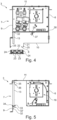
- the installer can pull the air filter 13, which is also replaceably or detachably attached to the housing 6, out of the housing through the air outlet 8, as in Figure 4 shown in a further sectional view.
- the air filter 13 is advantageously also held in the housing 6 by one or more locking elements.
- the pivot bearing 31 is also optionally assigned a condensate pan guide 37, which in particular forms a stop for the condensate pan 19, up to which the condensate pan 19 can be moved maximally in the direction of the pivot bearing 31.
- the condensate pan guide 37 is designed such that it limits the maximum tilt position of the condensate pan 19 or the pivoting path, thus ultimately defining the removal position of the condensate pan 19 by positively preventing further displacement of the condensate pan 19. This is also advantageous, for example, if the condensate pan 19 has a small width B2, which would allow pivoting of the condensate pan 19 in the area of the closed base 10, preventing such a movement.
- the air filter 13 is slidably mounted in the housing 6.
- the filter 13 can preferably be locked in the use position covering the air inlet 7 by one or more further locking elements in the housing 6.
- the air filter 13, as in Figure 5 shown in a further sectional view, can be arranged in a form-fitting manner on the air inlet 7 in a simple manner.
- the housing 6 has an air filter support 33 on the side wall 9, which is formed by a folded sheet metal, for example the housing wall 9.
- the support 33 forms in particular a Receiving pocket 34, into which the air filter 13 can be inserted from above, so that in the receiving pocket 34 it is safely prevented from slipping out of the air filter support 33.
- a guide plate 35 is arranged in the area of the ceiling wall 11 of the housing 6, which forms an insertion bevel 36 such that the air filter 13 can first be moved upwards along the insertion bevel 36 in the direction of the ceiling wall 11 for its assembly and is moved through the insertion bevel 36 with the upper end in the direction of the side wall 9, wherein the air filter 13 can be aligned at an angle to the side wall 9 in order to get past the air filter support 33.
- the lower end of the air filter 13 has overcome the air filter holder 33, it can be folded with the lower end towards the side wall 9 and then moved downwards to come to rest in the holder pocket 34.
- the guide plate 35 still holds the air filter 13 securely at its upper end in such a way that it covers the air inlet 7 and thus ensures that only filtered air can enter the housing 6 or the flow path through the housing 6.
- the air outlet 8 points vertically downwards
- the air outlet 8 is arranged or aligned parallel to the air inlet 7, so that a deflection of the air flow in the lower part of the housing 6 to the air outlet 8 is not necessary.
- the solution described above can also be achieved.
- the condensate tray 19 can be easily removed. Only the air filter 13 may have to be tilted further in order to reach the air outlet 8. In this case, a larger distance between the air filter 13 and the heat exchanger 14 may be necessary.
- the air filter 13 is designed as a foldable air filter 13, so that the distance between the air filter 13 and the heat exchanger 14 does not have to be increased.
- the invention is not limited to the illustrated arrangement of air inlet 7 and barrel outlet 8 relative to one another.
- an air supply connection 42 is arranged or designed to control the amount of fresh air in the to increase the room to be ventilated or air-conditioned.
- the fresh air is prepared in particular by a central air conditioning system and fed to device 3.
Landscapes
- Engineering & Computer Science (AREA)
- Chemical & Material Sciences (AREA)
- Combustion & Propulsion (AREA)
- Mechanical Engineering (AREA)
- General Engineering & Computer Science (AREA)
- Devices For Blowing Cold Air, Devices For Blowing Warm Air, And Means For Preventing Water Condensation In Air Conditioning Units (AREA)
- Air Filters, Heat-Exchange Apparatuses, And Housings Of Air-Conditioning Units (AREA)
Description
- Die Erfindung betrifft ein lufttechnisches Gerät zum Belüften und/oder Klimatisieren eines Raums eines Gebäudes oder dergleichen, mit einem Gehäuse, das einen Lufteinlass und einen Luftauslass aufweist, wobei zwischen Lufteinlass und Luftauslass ein Luftströmungsweg ausgebildet ist, welchem eine Luftfördereinrichtung einerseits und ein Luftfilter, ein Wärmetauscher und eine Kondensatwanne andererseits zugeordnet sind, und wobei dem Luftauslass eine an dem Gehäuse angeordnete und den Luftauslass überdeckende Schlitzauslassblende zugeordnet ist.
- Lufttechnische Geräte der eingangs genannten Art sind aus dem Stand der Technik bereits bekannt. Für den Einbau von lufttechnischen Geräten zum Belüften und/oder Klimatisieren von Räumen ist es in der Regel wünschenswert, dass das Gerät selbst für in dem Raum befindliche Personen weitestgehend versteckt ist, sodass die Optik des Raums durch das Gerät nicht gestört und somit eine flexible Raumgestaltung und -Nutzung ermöglicht sind. Üblicherweise erfolgt daher die Installation in einem Deckensprung oder in einer abgehängten Deckenwand, wobei nur der Luftauslass als solcher in der Decke erkennbar ist. Dazu werden das Gehäuse mit der darin befindlichen Luftfördereinrichtung und weiterer Elemente, wie beispielsweise Luftfilter, Wärmetauscher und/oder Kondensatwanne, oberhalb der Deckenwand angeordnet, sodass lediglich der Luftauslass durch eine Öffnung der Deckenwand führt. Dabei ist in dem Raum lediglich die Schlitzauslassblende sichtbar, welche den Luftauslass überdeckt und entsprechend ihrer Gestaltung für eine vorteilhafte Luftausströmung, beispielsweise in unterschiedliche Raumrichtungen, ausgebildet ist.
- Insbesondere der Luftfilter sowie die Kondensatwanne müssen jedoch regelmäßig inspiziert, gereinigt und/oder ausgetauscht werden, um einen dauerhaften hygienegerechten Betrieb des lufttechnischen Geräts zu ermöglichen. Um die Inspektion durchzuführen, muss bisher ein Monteur dazu das gesamte Gerät aus der Decke nehmen oder die Decke soweit öffnen, dass er an die wesentlichen Bestandteile des lufttechnischen Geräts herankommt, um Luftfilter und/oder Kondensatwanne austauschen beziehungsweise warten zu können.
- Aus der Offenlegungsschrift
DE 100 14 759 A1 ist ein lufttechnisches Gerät für den Deckeneinbau bekannt, das eine Filtereinheit aufweist, die durch eine Luftkanalöffnung nach Entfernen eines Lochgitters entnehmbar ist. Aus der OffenlegungsschriftDE 10 2015 006 762 A1 ist ein Unterflurklimatisierungsgerät bekannt, das einen Querstromventilator und einen Wärmetauscher umfasst. Aus der OffenlegungsschriftDE 20 2011 107 886 U1 ist eine Lüftungsgitter-Einsetzzargen-Anordnung bekannt, die beispielsweise zur Abdeckung einer Maueröffnung in einer Mauer eingesetzt werden kann. - Der Erfindung liegt die Aufgabe zugrunde, ein lufttechnisches Gerät der eingangs genannten Art zu schaffen, bei welchem die Wartung von Luftfilter und/oder Kondensatwanne vereinfacht und insbesondere ohne besonderen Aufwand für einen Monteur in kurzer Zeit durchführbar ist.
- Die der Erfindung zugrundeliegende Aufgabe wird durch ein lufttechnisches Gerät mit den Merkmalen des Anspruchs 1 gelöst. Dieses hat den Vorteil, dass der Monteur weder die Decke großflächig öffnen noch das lufttechnische Gerät aus der Decke entfernen muss, um an den Luftfilter und/oder die Kondensatwanne heranzukommen. Vielmehr erlaubt es die Erfindung nunmehr, dass der Monteur mit wenigen Handgriffen den Luftfilter und/oder die Kondensatwanne aus dem Gehäuse entfernt und beispielsweise austauscht oder reinigt. Erfindungsgemäß ist hierzu vorgesehen, dass die Schlitzauslassblende lösbar, insbesondere werkzeugfrei lösbar, an dem Gehäuse befestigt ist, und dass der Luftfilter und/oder die Kondensatwanne derart lösbar in dem Gehäuse befestigt sind, dass sie durch den Luftauslass aus dem Gehäuse entnehmbar sind. Der Luftfilter und/oder die Kondensatwanne sind somit derart ausgebildet und in dem Gehäuse angeordnet, dass sie durch den Luftauslass hindurch montiert und demontiert werden können. Der Luftauslass muss dazu mindestens einen Querschnitt aufweisen, der ein Hindurchführen von Luftfilter und/oder Kondensatwanne erlaubt. Zur Wartung beziehungsweise zum Austausch muss der Monteur nunmehr lediglich die Schlitzauslassblende von dem Gehäuse entfernen oder zumindest derart lösen, dass der Luftauslass freigegeben ist, und im Anschluss durch den Luftauslass hindurch den Luftfilter und/oder die Kondensatwanne greifen und aus dem Gehäuse entfernen. Hierdurch ist eine Wartung und/oder ein Austausch beispielsweise des Luftfilters in kurzer Zeit und ohne großen Aufwand möglich, sodass insbesondere die Wartung einer Vielzahl derartiger Geräte in einem Gebäude schnell und kostengünstig durchführbar ist. Darüber hinaus bleibt die Flexibilität bei der Gestaltung des Raums erhalten und wird gegebenenfalls sogar noch erhöht, weil mit einem Öffnen der Decke oder einem Ausbau des Geräts zur Wartung nicht gerechnet werden muss.
- Gemäß einer bevorzugten Weiterbildung der Erfindung ist vorgesehen, dass die Schlitzauslassblende durch zumindest ein elastisch verformbares oder verlagerbares erstes Rastelement an dem Gehäuse befestigt ist, um das werkzeugfrei Lösen und Befestigen der Schlitzauslassblende an dem Gehäuse zu realisieren. Die Schlitzauslassblende ist somit an dem Gehäuse verrastet gehalten, wobei die Verrastung durch eine elastische Verformung oder Verlagerung des Rastelements einfach lösbar ist. Damit kann der Monteur ganz ohne Werkzeug die Befestigung der Schlitzauslassblende lösen und so besonders bequem und einfach die Inspektion oder Wartung des Geräts durchführen. Vorzugsweise weist das Rastelement wenigstens ein Griffelement auf, das die Schlitzauslassblende durchgreift oder so zumindest derart an dieser angeordnet ist, dass der Monteur sie von außerhalb des Gehäuses betätigen kann, um das Rastelement von einer Arretierposition in eine Freigabeposition zu bewegen. Dazu ist das Griffelement bevorzugt einstückig mit dem Rastelement ausgebildet. Alternativ ist bevorzugt vorgesehen, dass das zumindest eine Rastelement derart ausgebildet ist, dass die durch das Rastelement aufgebrachte Haltekraft auch dadurch überwunden werden kann, dass die Schlitzauslassblende aus dem Luftauslass von dem Monteur herausgezogen wird. Dadurch ist ein besonders einfaches Lösen und Befestigen der Schlitzauslassblende werkzeuglos gewährleistet.
- Gemäß einer bevorzugten Weiterbildung der Erfindung ist vorgesehen, dass das zumindest eine erste Rastelement als elastisch verformbares Blattfederelement ausgebildet ist. Das Blattfederelement ist kostengünstig herstellbar und bauraumsparend in dem Gerät, insbesondere in dem Gehäuse anordenbar und nutzbar. Bevorzugt weist das Blattfederelement einen gewinkelten Verlauf auf, um einen Rastvorsprung zu bilden, der mit dem Gehäuse oder der Schlitzauslassblende verrastend zusammenwirkt. Wird eine ausreichend hohe Kraft auf die Schlitzauslassblende aufgebracht, so kann dann das verrastende Zusammenwirken durch elastische Verformung des ersten Rastelements aufgehoben werden. Hierdurch ist eine besonders einfache Rastvorrichtung verwirklicht.
- Bevorzugt ist das zumindest eine erste Rastelement an der Schlitzauslassblende gehalten. Damit verbleibt das Rastelement an der Schlitzauslassblende, wenn diese von dem Gehäuse entfernt wird. Alternativ ist das erste Rastelement an dem Gehäuse gehalten. Letzteres hat jedoch den Nachteil, dass der Freiraum, der zum Durchführen von Kondensatwanne und Luftfilter im Bereich des Luftauslass zur Verfügung steht, verkleinert wird. Daher ist vorteilhafterweise das Rastelement an der Schlitzauslassblende gehalten. Sind jedoch die Dimensionen des Luftauslass ausreichend groß gewählt, sodass die Position und Größe des ersten Rastelements das Entnehmen von Luftfilter und/oder Kondensatwanne nicht behindert, so ist das Rastelement bevorzugt an dem Gehäuse gehalten, sodass die Schlitzauslassblende selbst kostengünstiger ausgebildet werden kann.
- Gemäß einer bevorzugten Weiterbildung der Erfindung ist vorgesehen, dass das Gehäuse zumindest einen mit dem Rastelement zusammenwirkenden Rastvorsprung und/oder zumindest eine mit dem Rastelement zusammenwirkende Vertiefung aufweist. Rastelement und Rastvorsprung und/oder Rastvertiefung wirken verrastend für die Schlitzauslassblende und bilden somit zusammen eine Rastvorrichtung, durch welche die Schlitzauslassblende an dem Gehäuse lösbar gehalten ist.
- Weiterhin ist erfindungsgemäß vorgesehen, dass die Kondensatwanne in dem Gehäuse derart durch ein Schwenklager verschwenkbar gelagert ist, dass sie zwischen einer dem Wärmetauscher zugeordneten Gebrauchsstellung und einer insbesondere von dem Wärmetauscher entfernten Entnahmestellung verschwenkbar ist. Die Kondensatwanne ist also in dem Gehäuse verschwenkbar gelagert. In der Gebrauchsstellung ist sie dem Wärmetauscher zugeordnet, um an diesem entstehendes Kondensat aufzufangen und am Abtropfen in den darunterliegenden und zu belüftenden Raum zu hindern. In der Gebrauchsstellung ist die Kondensatwanne derart in dem Gehäuse gehalten, dass sich das Kondensat in dieser sammelt und nicht unkontrolliert abfließt. In der Entnahmestellung ist die Kondensatwanne derart verschwenkt, dass sie und/oder der Luftfilter aus dem Gehäuse entnehmbar sind. Insbesondere weist die Kondensatwanne ein allseitiges Gefälle beziehungsweise einen schräg verlaufenden/ausgerichteten Boden auf, der für das Kondensat eine Ablaufschräge bildet, durch welche das Kondensat gezielt insbesondere einem Abfluss zugeführt wird. So ist an dem Abfluss insbesondere ein Ablaufrohr oder - schlauch festgemacht, durch welchen das Kondensat aus der Kondensatwanne ablaufen kann. Bevorzugt ist dem Abfluss eine Absaugpumpe zugeordnet, die an der Kondensatwanne oder an dem Gehäuse, innerhalb oder außerhalb des lufttechnischen Geräts angeordnet ist. Ist die Absaugpumpe innerhalb des Geräts, insbesondere des Gehäuses angeordnet, so ist sie vorzugsweise zwischen der Kondensatwanne und dem Luftauslass angeordnet, so dass auch die Absaugpumpe durch den Luftauslass entnehmbar ist. Insbesondere ist dabei die Absaugpumpe lösbar, bevorzugt werkzeugfrei lösbar an dem Gehäuse oder der Kondensatwanne befestigt.
- In der Entnahmestellung ist die Kondensatwanne also derart ausgerichtet, dass sie durch den Luftauslass entnommen werden kann. Bevorzugt ist die Kondensatwanne in der Entnahmestellung derart verschwenkt, dass der Luftfilter an der Kondensatwanne vorbei durch den Luftauslass aus dem Gehäuse entnommen werden kann.
- Besonders bevorzugt ist das Schwenklager als Stecklager ausgebildet, das durch einen Lagerabschnitt der Kodensatwanne und einer Lageröffnung des Gehäuses gebildet ist. Dabei ist insbesondere vorgesehen, dass der Lagerabschnitt der Kondensatwanne die Lageröffnung des Gehäuses durchstößt und auf der Gehäuseoberseite, insbesondere eines Zwischenbodens des Gehäuses, aufliegt. An der Kante ist damit eine Schwenkachse zwischen Gehäuse und Kodensatwanne gebildet, um welche die Kodensatwanne an dem Gehäuse verschwenkbar ist. Hier ist insbesondere ein einfaches Schwenklager kostengünstig realisiert. Zur Herstellung des Schwenklagers ist die Kondensatwanne lediglich mit ihrem Lagerabschnitt in die Lageröffnung einsteckbar. Zur Demontage wird die Kodensatwanne einfach aus der Lageröffnung herausgezogen. Damit ist die Schwenklagerung der Kondensatwanne einfach bei der Montage herstellbar. Entsprechend einfach kann die Kondensatwanne auch aus dem Stecklager entfernt werden, indem sie aus dem Stecklager herausgezogen wird. Damit ist auch die Kondensatwanne besonders einfach aus dem Gehäuse entnehmbar. Alternativ ist vorgesehen, dass das Schwenklager eine Kondensatwannenaufnahme aufweist, die an dem Gehäuse verschwenkbar oder starr gelagert ist. Die Kondensatwannenaufnahme bildet somit zusammen mit der Kondensatwanne das Schwenklager. Ist die Kondensatwannenaufnahme starr gelagert, so bildet sie zusammen mit der Kondensatwanne beispielsweise einen Gelenkpunkt, an welchem die Kondensatwanne in der Kondensatwannenaufnahme verschwenkbar ist. Dies ist einfach und kostengünstig realisierbar. Ist die Kondensatwannenaufnahme alternativ selbst verschwenkbar in dem Gehäuse gelagert, so ist durch die Kondensatwannenaufnahme eine Führung der Kondensatwanne beim Verschwenken von der Entnahmeposition in die Gebrauchsposition und zurück in vorteilhafter Weise gewährleistet, die insbesondere sicherstellt, dass die Montage und Demontage der Kondensatwanne fehlerfrei erfolgt. Die Kondensatwannenaufnahme kann dazu beispielsweise um eine Schwenkachse an dem Gehäuse verschwenkbar gelagert sein, die durch ein einfaches Drehgelenk gebildet ist.
- Bevorzugt ist dem Schwenklager eine Kondensatwannenführung für die Kondensatwanne zugeordnet, die insbesondere den Verschwenkweg der Kondensatwanne in Richtung der Entnahmestellung begrenzt. Die Kondensatwannenführung erleichtert einerseits das Herstellen des Schwenklagers, sodass eine Fehlmontage verhindert wird. Andererseits begrenzt die Kondensatwannenführung bevorzugt den Verschwenkweg der Kondensatwanne, sodass durch die Kondensatwannenführung sichergestellt ist, dass die Kondensatwanne, wenn sie aus der Verrastung gelöst wird, nicht in das Gehäuse des Geräts fällt, sondern insbesondere in Richtung des Luftauslass. Durch das Begrenzen des Verschwenkwegs wird erreicht, dass die Kondensatwanne beispielsweise nicht auf den Gehäuseboden fällt und damit für den Monteur nicht mehr durch den Luftauslass erreichbar ist.
- Gemäß einer vorteilhaften Weiterbildung der Erfindung ist bevorzugt vorgesehen, dass an dem Gehäuse und/oder an der Kondensatwanne wenigstens ein zweites Rastelement angeordnet ist, mittels dessen die Kondensatwanne in der Gebrauchsposition arretierbar ist. Um sicherzustellen, dass die Kondensatwanne in der Gebrauchsstellung verbleibt und nicht selbsttätig in die Entnahmestellung schwenkt, ist dieser also zumindest ein zweites Rastelement zugeordnet. Das zweite Rastelement ist an dem Gehäuse oder an der Kondensatwanne angeordnet, um ein sicheres Verrasten in der Gebrauchsstellung zu erreichen. Das zweite Rastelement ist bevorzugt wie das erste Rastelement ausgebildet, wodurch sich die bereits genannten Vorteile ergeben. Durch die verrastende Arretierung der Kondensatwanne in der Gebrauchsstellung ist außerdem ebenfalls eine werkzeugfreie Montage und Demontage der Kondensatwanne möglich, wodurch Montage und Demontage weiter vereinfacht werden. Bevorzugt ist das zweite Rastelement derart ausgebildet, dass es eine formschlüssige Auflagefläche für die Kondensatwanne in der Gebrauchsstellung bietet, sodass ein versehentliches Lösen der Kondensatwanne, beispielsweise aufgrund einer steigenden Gewichtsbelastung durch eine zunehmende Kondensatmenge, sicher verhindert ist. Das zweite Rastelement weist somit bevorzugt einen horizontal verlaufenden Abschnitt auf, der als Auflage für die Kondensatwanne dient, und der nicht durch eine auf die Kondensatwanne wirkende Kraft überwunden werden kann.
- Vorzugsweise ist die Kondensatwanne unterhalb des Wärmetauschers angeordnet. Dadurch ist sichergestellt, dass von dem Wärmetauscher oder an dem Wärmetauscher entstehendes Kondensat in die Kondensatwanne gelangt und dort sicher aufgefangen wird.
- Weiterhin ist bevorzugt vorgesehen, dass der Luftfilter stromaufwärts des Wärmetauschers oberhalb des Luftauslass angeordnet ist. Dadurch liegt der Luftfilter im Strömungsweg noch vor dem Wärmetauscher und oberhalb des Luftauslass, sodass er einfach durch den Luftauslass aus dem Gehäuse entnommen werden kann. Der Wärmetauscher kann dabei ebenfalls bereichsweise oberhalb des Luftauslass und damit von dem Monteur erreichbar angeordnet sein. Vorzugsweise ist er zumindest teils neben dem Luftauslass angeordnet, sodass er und der Luftauslass sich bereichsweise überschneiden. Hierdurch ergibt sich der Vorteil, dass der Wärmetauscher besonders sicher an dem Gehäuse gehalten ist und nicht ausversehen durch den Luftauslass aus dem Gehäuse herausfallen kann. Vorzugsweise ist der Luftauslass derart schmal ausgebildet, dass ein Hindurchführen des Wärmetauschers durch den Luftauslass nicht möglich ist. Dadurch, dass der Luftfilter oberhalb des Luftauslass angeordnet ist, ist ein einfaches Entnehmen des Luftfilters sowie ein einfaches Einsetzen des Luftfilters in das Gehäuse möglich.
- Weiterhin ist bevorzugt vorgesehen, dass das Gehäuse eine Filteraufnahme für den Luftfilter aufweist, in welcher der Luftfilter einschiebbar/einsteckbar ist, wobei der Filteraufnahme optional zumindest ein drittes Rastelement zum Arretieren des Luftfilters in der Filteraufnahme zugeordnet ist. Vorteilhafterweise ist die Filteraufnahme als Schiebeaufnahme ausgebildet, in welche der Luftfilter einschiebbar ist, um seine Endmontageposition zu erreichen. Bevorzugt ist die Filteraufnahme derart ausgebildet, dass der Luftfilter in der Filteraufnahme formschlüssig gehalten ist. Dazu weist die Filteraufnahme bevorzugt eine Aufnahmetasche auf, in welche der Filter einsetzbar ist, indem er von oben vertikal in die Filteraufnahme bereichsweise, insbesondere randseitig eingeschoben wird. Dadurch ist eine einfache Anordnung und Arretierung des Luftfilters an dem Gehäuse gewährleistet. Optional ist dem der Filteraufnahme gegenüberliegenden Ende des Luftfilters ein Führungsblech oder ein Führungselement zugeordnet, welches den Luftfilter in der aufgerichteten Position hält, jedoch eine Schwenkbewegung erlaubt, sodass der Filter aus der Filteraufnahme herausgehoben werden und anschließend zumindest um einen vorgebbaren Winkel derart verkippt werden kann, dass sein unteres Ende von der Filteraufnahme zur Seite weggeschoben wird. Das dritte Rastelement ist bevorzugt wie das erste und/oder das zweite Rastelement ausgebildet. Das optionale dritte Rastelement arretiert den Luftfilter in der Endmontageposition form- und/oder kraftschlüssig, sodass sichergestellt ist, dass Luft nicht an dem Luftfilter vorbei zu der Luftfördereinrichtung gelangt.
- Weiterhin ist bevorzugt vorgesehen, dass der Luftfilter schmaler ausgebildet ist als die Kondensatwanne. Dadurch ist sichergestellt, dass der Luftfilter durch den Luftauslass entfernt werden kann, auch wenn eine oder mehrere Rastelemente mit der Kondensatwanne zusammenwirken. Zweckmäßigerweise ist die Kondensatwanne derart breit ausgebildet, dass die mit ihr zusammenwirkenden Rastelemente derart weit voneinander beabstandet sind, dass der Luftfilter zwischen diesen hindurch zu dem Luftauslass geführt werden kann.
- Im Folgenden soll die Erfindung anhand der Zeichnung näher erläutert werden. Dazu zeigen
- Figur 1
- eine vorteilhafte Belüftungsanordnung mit einem lufttechnischen Gerät in einer perspektivischen vereinfachten Darstellung,
- Figur 2
- eine erste Schnittdarstellung durch das lufttechnische Gerät,
- Figur 3
- eine zweite Schnittdarstellung durch das lufttechnische Gerät,
- Figur 4
- eine dritte Schnittdarstellung durch das lufttechnische Gerät und
- Figur 5
- eine vierte Schnittdarstellung durch das lufttechnische Gerät.
-
Figur 1 zeigt in einer vereinfachten perspektivischen Darstellung eine vorteilhafte Belüftungsanordnung 1, die ein an einer Decke 2 eines hier nicht näher dargestellten Raums eines Gebäudes angeordnetes lufttechnisches Gerät 3 aufweist. Das Gerät 3 ist dazu ausgebildet, den Raum zu belüften und/oder zu klimatisieren. Das lufttechnische Gerät 3 ist dabei oberhalb einer Deckenwand 4 der Decke 2 in der Decke 2 angeordnet. Die Deckenwand 4 wird beispielsweise durch eine abgehängte Decke oder Deckenelement als Zwischendecke gebildet. Dabei weist die Deckenwand 4 eine schlitzförmige Öffnung 5 auf, welcher das Gerät 3 zugeordnet ist. Das Gerät 3 weist grundsätzlich ein Gehäuse 6 auf, das einen Lufteinlass 7 sowie einen Luftauslass 8 aufweist, wobei von dem Lufteinlass 7 zu dem Luftauslass 8 in dem Gehäuse 6 ein Strömungsweg ausgebildet ist, sodass Luft von dem Lufteinlass 7 zu dem Luftauslass 8 gelangt. Der Luftauslass 8 ist dabei der Öffnung 5 der Decke 2 zugeordnet, sodass die aus dem Gehäuse 6 austretende Luft in den darunterliegenden Raum eintreten kann. -
Figur 2 zeigt das Gerät 3 in einer vereinfachten ersten Schnittdarstellung durch das Gehäuse 6. In der inFigur 2 gezeigten Darstellung ist der Lufteinlass 7 in einer ersten Seitenwand auf der linken Seite des Gehäuses ausgebildet, während der Luftauslass 8 in einen Boden 10 des Gehäuses 6 ausgebildet ist. Eine Deckenwand 11 des Gehäuses sowie eine zweite Seitenwand 12 auf der rechten Seite des Gehäuses 6 sind hingegen zumindest im Wesentlichen geschlossen ausgebildet. Ein Strömungsweg vom Lufteinlass 7 zu dem Luftauslass 8 bedingt somit eine Richtungsänderung des Luftstroms. - Dem Lufteinlass 7 ist ein Luftfilter 13 zugeordnet, welcher den Lufteinlass 7 derart überdeckt, dass nur durch den Luftfilter 13 gefilterte Luft in das Gehäuse 6 gelangt. Der Lufteinlass 7 liegt dabei oberhalb des Luftauslass 8, sodass er innerhalb der Decke 2 liegt und damit in dem Zwischenraum der Decke 2 befindliche Luft einlässt.
- Stromabwärts des Luftfilters 13 ist in dem Gehäuse ein Wärmetauscher 14 angeordnet, welcher von der eintretenden Luft durchströmt wird. Der Wärmetauscher 14 ist beispielsweise ein Flüssigkeitswärmetauscher, der mehrere Flüssigkeitskanäle 15 aufweist, wie in
Figur 2 beispielhaft gezeigt. Durch die Flüssigkeitskanäle wird bei Bedarf eine gekühlte oder erhitzte gekühlte Flüssigkeit geführt, um die durch den Wärmetauscher 14 geführte Frischluft zu kühlen oder zu erhitzen. - Stromabwärts des Wärmetauschers 14 ist eine Luftfördereinrichtung 16 angeordnet, die gemäß dem vorliegenden Ausführungsbeispiel einen Querstromventilator aufweist. Dem Querstromventilator zugeordnet ist außerdem ein Luftleitblech oder -Element 17, welches die Effizienz des Querstromventilators erhöht. Dem Querstromventilator 16 ist ein ansteuerbarer Antrieb 18 zugeordnet, der insbesondere als Elektromotor ausgebildet ist, um eine Drehzahl des Querstromventilators variabel einstellen und insbesondere an einem aktuellen Bedarf anzupassen zu können. Die Luftfördereinrichtung 16 ist derart ausgebildet, dass der durch den Luftfilter 7 und den Wärmetauscher 14 angesaugte Luftstrom, in
Figur 2 durch Pfeile beispielhaft gezeigt, durch den Querstromventilator um circa 90° nach unten umgelenkt und in einen unteren Teil des Gehäuses 6 gefördert wird, in welchem der Luftauslass 8 ausgebildet ist. Der Luftauslass 8 ist dabei unterhalb des Wärmetauschers 14 und des Luftfilters 13 angeordnet, und vertikal nach unten gerichtet, sodass der Luftstrom in dem Gehäuse 6 unterhalb des Querstromventilators nochmals um circa 90° umgelenkt wird, um dem Luftauslass 8 zugeführt zu werden. - Unterhalb des Wärmetauschers 14 ist außerdem in dem Gehäuse 6 eine Kondensatwanne 19 angeordnet. Die Kondensatwanne 19 ist dazu ausgebildet und angeordnet, um an dem Wärmetauscher 14 kondensierte Flüssigkeit aufzufangen und am Ausfließen aus dem Gehäuse 6 zu hindern. Dazu weist die Kondensatwanne 19 im Querschnitt ein wannenförmiges Profil auf, wobei vorliegend ein Wannenboden 20 der Kondensatwanne 19 in der in
Figur 2 dargestellten Gebrauchsposition schräg in Bezug auf eine Horizontale beziehungsweise in Bezug auf die Deckenwand 4 ausgerichtet ist, und zwar derart, dass die in den unteren Teil des Gehäuses gelangende Luftströmung entlang der Unterseite des Wannenbodens 20 nach unten in Richtung des Luftauslass 8 geführt wird, sodass Verwirbelungen vermieden und die Effizienz des Geräts 3 verbessert wird. Außerdem hat die Schräge des Wannenbodens 20, die insbesondere ein allseitiges Gefälle ist, die Aufgabe, das angefallene Kondensat abzuführen. Dazu weißt die Kondensatwanne 19 an ihrer tiefsten Stelle einen Abfluss 40 auf, an welchem ein Ablaufrohr oder -schlauch befestigt oder befestigbar ist, um das aufgefangene Kondensat abzuführen. Der Ablaufschlauch oder das Ablaufrohr ist insbesondere mit einer Absaupumpe 41 verbunden, mittels welcher das Kondensat aktiv abgesaugt werden kann. Die Absaugpumpe 41 ist insbesondere zwischen der Kondensatwanne 19 und dem Gehäuseboden 10 angeordnet und lösbar beispielsweise an dem Gehäuse 6, wie dargestellt, oder an der Kondensatwanne 19 befestigt. - Das Gehäuse 6 weist in dem unteren Bereich am Boden 10 einen nach unten vorstehenden Flansch 21 auf, welcher den Luftauslass 8 in dem Boden 10 bildet. Der Flansch 21 ist derart ausgebildet, dass er die Öffnung 5 der Decke 2 beziehungsweise Deckenwand 4 zumindest im Wesentlichen durchragt und damit die Luft direkt in den zu belüftenden beziehungsweise zu klimatisierenden Raum lenkt. In den Flansch 21 ist eine vorteilhafte Schlitzauslassblende 22 eingesetzt, welche den Luftauslass 8 und gegebenenfalls einen Abschnitt der Deckenwand 4 beidseits des Luftauslass 8 überdeckt, sodass sämtliche durch den Luftauslass 8 ausströmende Luft durch die Schlitzauslassblende 22 geführt wird. Die Schlitzauslassblende 22 weist dabei vorteilhafterweise, wie in
Figur 2 dargestellt, mehrere Luftleitelemente 23 auf, welche für eine vorteilhafte Luftausströmung dienen, welche insbesondere derart gestaltet ist, dass die Luft unterhalb des Gehäuses 6 und der Deckenwand 4 insbesondere seitlich beziehungsweise horizontal ausströmt, sodass sie zumindest abschnittsweise zunächst parallel zur Deckenwand 4 strömt, bevor sie in den darunterliegenden Raum fällt. - Gemäß dem vorliegenden Ausführungsbeispiel sind die Schlitzauslassblende 22, die Kondensatwanne 19 sowie der Luftfilter 13 lösbar an dem Gehäuse 6 befestigt. Dabei sind der Luftfilter 13, die Kondensatwanne 19 und der Luftauslass 8 derart zueinander an dem Gehäuse 6 ausgebildet beziehungsweise angeordnet, dass der Luftfilter 13 und die Kondensatwanne 19 durch den Luftauslass 8 entnommen werden können. Dazu ist der Luftauslass 8 unterhalb des Luftfilters 13 und zumindest im Wesentlichen unterhalb der Kondensatwanne 19 angeordnet. Der Luftauslass 8 ist dabei mindestens so breit, dass Luftfilter 13 und Kondensatwanne 19 hindurchgeführt werden können. Der Luftfilter 13 liegt dabei direkt oberhalb des Luftauslass 8 und die Kondensatwanne 19 zumindest bereichsweise direkt oberhalb des Luftauslass 8.
- In Bezug auf die Darstellung von
Figur 2 weist der Luftauslass 8 eine Breite B1 auf, die Kondensatwanne eine Breite B2 und der Luftfilter 13 eine Breite B3. Die Breite B3 ist dabei wesentlich kleiner als die Breite B1 des Luftauslass 8, sodass der Luftfilter 13 problemlos durch den Luftauslass 8 aus dem Gehäuse 6 entfernt werden kann. Die Breite B2 der Kondensatwanne 19 ist größer als die Breite B1, weil aufgrund der Größe des Wärmetauschers 14 eine ausreichende Breite der Kondensatwanne 19 zum Auffangen des gebildeten Kondensats gewährleistet sein muss. Um die Kondensatwanne 19 aus dem Luftauslass 8 ausführen zu können, weist sie jedoch eine Höhe H2 auf, welche schmaler ist als die Breite B1 des Luftauslass 8. Somit kann die Kondensatwanne 19 durch ein Verkippen um etwa 90° aus der Gebrauchsstellung ebenfalls durch den Luftauslass 8 aus dem Gehäuse 6 entnommen werden. -
Figur 3 zeigt dazu in einer weiteren Schnittdarstellung das Gerät 3 in einem Zustand, in welchem die Schlitzauslassblende 22 von dem Luftauslass 8 entfernt und die Kondensatwanne 19 in eine Entnahmestellung verlagert wurde. Die Schlitzauslassblende 22 ist durch mehrere elastisch verformbare Rastelemente 24 an dem Gehäuse 6 befestigbar. Dazu weist das Gehäuse 6 an dem Flansch 21 auslassseitig nach innen weisende umgekantete Enden des Flansch 21 auf, die einen in dem Flansch 21 bildenden Rastvorsprung 25 bilden. Die Rastvorsprünge 25 definieren dabei die maximale Breite B1 des Luftauslass 8. An der Schlitzauslassblende 22 sind die mehreren Rastelemente 24 an den Längsseiten beabstandet zueinander angeordnet, sodass sie seitlich vorstehen. Die Rastelemente 24 sind dabei vorliegend in der Art von Blattfedern 26 ausgebildet, die einen A- oder V-förmigen Verlauf, also einen winkelförmigen Verlauf, aufweisen, und ihrerseits einen Rastvorsprung 27, der von der Schlitzauslassblende 22 seitlich vorsteht, zu bilden. Dabei sind die Spitzen der Rastvorsprünge 27 weiter voneinander entfernt als die Breite B1 gewählt ist, sodass die Spitzen beziehungsweise Rastvorsprünge 27 über die Rastvorsprünge 25 hinausragen, wenn sie sich in ihrem entlasteten beziehungsweise entspannten Zustand befinden. Um die Schlitzauslassblende 22 an dem Luftauslass 8 zu arretieren, wird sie linear in den Luftauslass 8 eingeführt, wodurch die V-förmigen Rastelemente 24 beim Einführen unter elastischer Verformung nach innen gedrängt werden, sodass die Rastvorsprünge 27 an den Rastvorsprüngen 25 vorbeigeschoben werden können. Sobald die Rastvorsprünge 25 überwunden wurden, werden die Rastvorsprünge 27 aufgrund der Eigenelastizität der Rastelemente 24 wieder nach außen gedrängt, sodass sie die Rastvorsprünge 25 überragen und diese formschlüssig hintergreifen. Dadurch ist die Schlitzauslassblende 22 in einfacher Art und Weise formschlüssig an dem Gehäuse 2 beziehungsweise dem Flansch 21 arretiert. Um die Schlitzauslassblende 22 von einem Gehäuse zu lösen, kann diese einfach mit einer entsprechend hohen Kraft nach unten gezogen werden, sodass die Rastelemente 24 erneut unter elastischer Verformung ein Lösen der Schlitzauslassblende 22 erlauben. Alternativ kann auch ein Werkzeug zur Hilfe genommen werden, um die Rastelemente 24 vor dem Hinausziehen der Schlitzauslassblende 22 zurückzudrängen. - Die Kodensatwanne 19 ist in dem Gehäuse 6 verschwenkbar gelagert. Dazu weist sie an ihrer einen Längsseite, die aufgrund der schrägen Ausrichtung des Bodens 10 eine niedrigere Höhe als die Höhe H2 aufweist, einen seitlich vorstehenden Lagerabschnitt 28 auf, der durch eine Öffnung 29 in einem Zwischenboden 30 des Gehäuses hindurchführbar ist, wie in
Figur 3 gezeigt. - Der Lagerabschnitt 28 steht dabei derart seitlich von der Kodensatwanne 19 vor, dass er in der Gebrauchsstellung auf dem Zwischenboden 30 flächig aufliegt. An einer die Öffnung 29 begrenzenden Kante ist somit die Kodensatwanne 19 um diese Kante herum verschwenkbar gelagert, sodass sie zwischen der in
Figur 3 gezeigten Entnahmestellung und der inFigur 2 gezeigten Gebrauchsstellung in und her bewegbar ist. Der Lagerabschnitt 28, der in einem Winkel von einer Seitenwand der Kodensatwanne 19 vorsteht, bildet somit zusammen mit dem Zwischenboden 30 ein Schwenklager 31 für die Kodensatwanne 19, das einfach durch Einschieben des Lagerabschnitts 28 durch die Öffnung 29 herstellbar und durch Herausziehen der Kodensatwanne 19 mit dem Lagerabschnitt 28 aus der Öffnung 29 lösbar ist. Das Schwenklager 31 ist dabei derart angeordnet, dass die Kodensatwanne 19 aus der Gebrauchsposition in die Entnahmeposition derart verschwenkbar ist, dass die Kodensatwanne 19 mit dem von dem Schwenklager 31 abgewandten Ende in den Luftauslass 8 fällt, sodass ein Monteur die Kodensatwanne 19 einfach durch den Luftauslass 8 herausziehen und damit vom Gehäuse 6 entfernen kann. In der Entnahmestellung, wie sie inFigur 3 gezeigt ist, wird dabei außerdem zwischen der Kodensatwanne 19 und der Seitenwand 9 ein Abstand hergestellt, der es erlaubt, dass der Luftfilter 13 bei Bedarf an der Kodensatwanne 19 vorbei aus dem Gehäuse 6 herausgenommen werden kann. - Wird die Kodensatwanne 19 in die Gebrauchsstellung nach oben verschwenkt, so wird sie dort durch ein oder mehrere Rastelemente 32 formschlüssig gehalten. Dabei ist das jeweilige Rastelement 32 zweckmäßigerweise an der Seitenwand 9 des Gehäuses 6 befestigt und ragt in den Bewegungsbeweg der Kodensatwanne 19 vor. Das oder die Rastelemente 32 sind gemäß dem vorliegenden Ausführungsbeispiel ebenfalls blattfederartig ausgebildet und weisen einen keilförmigen Verlauf auf, sodass sie eine Anlaufschräge für die Kodensatwanne 19 beim Verbringen in die Gebrauchsstellung bilden und dadurch von der Kodensatwanne 19 in eine Freigabeposition elastisch zurückgedrängt werden. Sobald die Kodensatwanne 19 einen von dem jeweiligen Rastelement gebildeten Rastvorsprung 32' überwunden hat, schnappt das jeweilige Rastelement 32 aufgrund seiner Eigenelastizität zurück, sodass es die Kodensatwanne 19 an ihrem von dem Lagerabschnitt 28 abgewandten Längsseite hintergreift und eine horizontale Auflage für die Kodensatwanne 19 bildet. Damit ist die Kodensatwanne 19 formschlüssig an dem Gehäuse 2 durch das oder die Rastelemente 32 gehalten. Um die Kodensatwanne 19 aus dem Gehäuse zu lösen, muss lediglich das jeweilige Rastelement 32 in die Freigabeposition elastisch verformt werden, sodass die Kodensatwanne 19 nach unten an dem Rastelement 32 vorbeigeschwenkt werden kann, wie in
Figur 3 gezeigt. Das jeweilige Rastelement 32 kann dabei durch den Monteur manuell oder mithilfe eines Werkzeugs in die Freigabeposition verlagert werden. Durch die formschlüssige Arretierung einer Gebrauchsstellung ist ein sicherer Halt der Kodensatwanne 19 im Normalfall dauerhaft gewährleistet. - Sobald der Monteur die Schlitzauslassblende 22 sowie die Kodensatwanne 19 aus dem Gehäuse 6 entfernt hat, wie beispielsweise in
Figur 4 gezeigt, kann er den Luftfilter 13, der ebenfalls austauschbar beziehungsweise lösbar an dem Gehäuse 6 befestigt ist, aus dem Gehäuse durch den Luftauslass 8 herausziehen, wie inFigur 4 in einer weiteren Schnittdarstellung gezeigt. Vorteilhafterweise ist der Luftfilter 13 ebenfalls durch ein oder mehrere Rastelemente in dem Gehäuse 6 gehalten. - Dem Schwenklager 31 ist außerdem optional eine Kodensatwannenführung 37 zugeordnet, welche insbesondere einen Anschlag für die Kodensatwanne 19 bildet, bis zu welchem die Kodensatwanne 19 maximal in Richtung des Schwenklagers 31 verschiebbar ist. Außerdem ist die Kodensatwannenführung 37 derart ausgebildet, dass sie die maximale Kippstellung der Kondensatwanne 19 beziehungsweise den Verschwenkweg begrenzt, also letztendlich die Entnahmestellung der Kodensatwanne 19, definiert, indem sie ein weiteres Verlagern der Kodensatwanne 19 formschlüssig verhindert. Dies ist beispielsweise auch dann von Vorteil, wenn die Kodensatwanne 19 eine geringe Breite B2 aufweist, die ein Verschwenken der Kodensatwanne 19 in dem Bereich des geschlossenen Bodens 10 erlauben würde, eine derartige Bewegung verhindert.
- Wie in
Figur 4 ersichtlich, ist der Luftfilter 13 verschiebbar in dem Gehäuse 6 gelagert. Dabei ist der Filter 13 bevorzugt durch eine oder mehrere weitere Rastelemente in dem Gehäuse 6 in der den Lufteinlass 7 überdeckenden Gebrauchsposition arretierbar. - Alternativ ist der Luftfilter 13, wie in
Figur 5 in einer weiteren Schnittdarstellung gezeigt, formschlüssig auf einfache Art und Weise an dem Lufteinlass 7 anordenbar. Dazu weist das Gehäuse 6 an der Seitenwand 9 einen Luftfilterauflage 33 auf, die durch ein umgekantetes Blech, beispielsweise der Gehäusewand 9, gebildet ist. Die Auflage 33 bildet insbesondere eine Aufnahmetasche 34, in welche der Luftfilter 13 von oben einsetzbar ist, sodass er in der Aufnahmetasche 34 sicher vor einem Herausrutschen von der Luftfilterauflage 33 gehindert ist. Um den Luftfilter 13 in die sichere Gebrauchsposition zu verbringen, ist im Bereich der Deckenwand 11 des Gehäuses 6 ein Leitblech 35 angeordnet, welches eine Einführschräge 36 derart bildet, dass entlang der Einführschräge 36 der Luftfilter 13 zu seiner Montage zunächst nach oben in Richtung der Deckenwand 11 bewegbar ist und durch die Einführschräge 36 mit dem oberen Ende in Richtung der Seitenwand 9 bewegt wird, wobei der Luftfilter 13 dabei schräg zu der Seitenwand 9 ausgerichtet sein kann, um an der Luftfilterauflage 33 vorbeizukommen. Sobald das untere Ende des Luftfilters 13 die Luftfilteraufnahme 33 überwunden hat, kann er mit dem unteren Ende in Richtung der Seitenwand 9 angeklappt werden und dann nach unten bewegt werden, um in der Aufnahmetasche 34 zum Liegen zu kommen. Durch das Führungsblech 35 ist der Luftfilter 13 dabei immer noch an seinem oberen Ende sicher derart gehalten, dass er den Lufteinlass 7 überdeckt und dadurch gewährleistet, dass nur gefilterte Luft in das Gehäuse 6 beziehungsweise den Strömungsweg durch das Gehäuse 6 gelangen kann. - Während in den vorliegenden Ausführungsbeispielen gezeigt ist, dass der Luftauslass 8 vertikal nach unten weist, ist es gemäß einem weiteren Ausführungsbeispiel, hier nicht dargestellt, vorgesehen, dass der Luftauslass 8 parallel zu dem Lufteinlass 7 angeordnet beziehungsweise ausgerichtet ist, sodass eine Umlenkung des Luftstroms in dem Unterteil des Gehäuses 6 zu dem Luftauslass 8 nicht notwendig ist. Durch eine entsprechende Anordnung von Luftfilter 13, Kondensatwanne 19 und Luftauslass 8 zueinander, ist auch dabei die vorbeschriebene Lösung erreichbar. Das Herausführen der Kondensatwanne 19 ist ohne weiteres möglich. Lediglich der Luftfilter 13 muss gegebenenfalls weiter verkippt werden, um zu dem Luftauslass 8 zu gelangen. In diesem Fall ist gegebenenfalls ein größerer Abstand zwischen Luftfilter 13 und Wärmetauscher 14 notwendig. Zusätzlich oder alternativ ist der Luftfilter 13 als faltbarer Luftfilter 13 ausgebildet, so dass der Abstand zwischen Luftfilter 13 und Wärmetauscher 14 nicht vergrößert werden muss. Es ist jedoch ohne weiteres nachvollziehbar, dass die Erfindung nicht auf die dargestellte Anordnung von Lufteinlass 7 und Lauf auslass 8 zueinander beschränkt ist.
- Außerdem ist optional an dem Gehäuse 6, insbesondere im unteren Teil, wie in
Figur 3 gezeigt, ein Zuluftanschluss 42 angeordnet oder ausgebildet, um die Frischluftmenge in dem zu belüftenden beziehungsweise zu klimatisierenden Raum zu erhöhen. Die Frischluft wird dabei insbesondere von einer zentralen Klimaanlage aufbereitet und dem Gerät 3 zugeführt.
Claims (13)
- Lufttechnisches Gerät (3) zum Belüften und/oder Klimatisieren des Raums, wobei das lufttechnische Gerät (3) ein Gehäuse (6) aufweist, das einen Lufteinlass (7) und einen Luftauslass (8) aufweist, wobei zwischen Lufteinlass (7) und Luftauslass (8) ein Luftströmungsweg durch das Gehäuse (6) ausgebildet ist, welchem eine Luftfördereinrichtung (16) einerseits und ein dem Lufteinlass (7) zugeordneter Luftfilter (13), ein Wärmetauscher (14) und eine Kodensatwanne (19) andererseits zugeordnet sind, wobei der Luftfilter (13) den Lufteinlass (7) derart überdeckt, dass nur durch den Luftfilter (13) gefilterte Luft in das Gehäuse (6) gelangt, wobei dem Luftauslass (8) eine an dem Gehäuse (6) angeordnete und den Luftauslass (8) überdeckende Schlitzauslassblende (22) zugeordnet ist, wobei die Schlitzauslassblende (22) lösbar an dem Gehäuse (6) befestigt ist, wobei der Luftfilter (13) und die Kodensatwanne (19) derart lösbar in dem Gehäuse befestigt sind, dass sie durch den Luftauslass (8) aus dem Gehäuse (6) entnehmbar sind, wobei der Luftauslass (8) eine Breite (B1), die Kondensatwanne (19) eine Breite (B2) und der Luftfilter (13) eine Breite (B3) aufweisen, wobei die Breite (B3) des Luftfilters (13) wesentlich kleiner ist als die Breite (B 1) des Luftauslasses (8), und wobei die Breite (B2) der Kondensatwanne (19) größer ist als die Breite (B1) des Luftauslasses (8), wobei die Kondensatwanne (19) in dem Gehäuse (6) derart durch ein Schwenklager (31) verschwenkbar gelagert ist, dass sie zwischen einer dem Wärmetauscher (14) zugeordneten Gebrauchsstellung und einer Entnahmestellung verschwenkbar ist, und wobei in der Entnahmestellung die Kondensatwanne (19) aus dem Gehäuse durch den Luftauslass (8) entnehmbar ist, wobei bevorzugt der Luftfilter (13) an der Kondensatwanne vorbei aus dem Gehäuse (6) durch den Luftauslass (8) entnehmbar ist.
- Lufttechnisches Gerät nach Anspruch 1, dadurch gekennzeichnet, dass die Schlitzauslassblende (22) durch zumindest ein elastisch verformbares oder verlagerbares erstes Rastelement (24) an dem Gehäuse befestigt ist.
- Lufttechnisches Gerät nach einem der vorhergehenden Ansprüche, dadurch gekennzeichnet, dass das zumindest eine erste Rastelement (24) als elastisch verformbares Blattfederelement ausgebildet ist.
- Lufttechnisches Gerät nach einem der vorhergehenden Ansprüche, dadurch gekennzeichnet, dass das zumindest eine erste Rastelement (24) an der Schlitzauslassblende (22) gehalten ist.
- Lufttechnisches Gerät nach einem der vorhergehenden Ansprüche, dadurch gekennzeichnet, dass das Gehäuse (6) zumindest einen mit dem ersten Rastelement (24) zusammenwirkenden Rastvorsprung (25) und/oder zumindest eine mit dem ersten Rastelement (24) zusammenwirkende Vertiefung aufweist.
- Lufttechnisches Gerät nach einem der vorhergehenden Ansprüche, dadurch gekennzeichnet, dass das Schwenklager (31) als Stecklager ausgebildet ist, das durch einen Lagerabschnitt der Kondensatwanne und einer Lageröffnung (29) des Gehäuses (6) gebildet ist.
- Lufttechnisches Gerät nach einem der vorhergehenden Ansprüche, dadurch gekennzeichnet, dass dem Schwenklager (31) eine Kondensatwannenführung (37) für die Kondensatwanne (19) zugeordnet ist, die insbesondere den Verschwenkweg der Kondensatorwanne (19) in Richtung der Entnahmestellung begrenzt.
- Lufttechnisches Gerät nach einem der vorhergehenden Ansprüche, dadurch gekennzeichnet, dass an dem Gehäuse (6) und/oder an der Kondensatwanne (19) wenigstens ein zweites Rastelement (32) angeordnet ist, mittels dessen die Kondensatwanne (19) in der Gebrauchsstellung arretierbar ist.
- Lufttechnisches Gerät nach einem der vorhergehenden Ansprüche, dadurch gekennzeichnet, dass die Kondensatwanne (19) unterhalb des Wärmetauschers (14) angeordnet ist.
- Lufttechnisches Gerät nach einem der vorhergehenden Ansprüche, dadurch gekennzeichnet, dass der Luftfilter (13) stromaufwärts des Wärmetauschers (14) oberhalb des Luftauslass (8) angeordnet ist.
- Lufttechnisches Gerät nach einem der vorhergehenden Ansprüche, dadurch gekennzeichnet, dass das Gehäuse (6) eine Luftfilteraufnahme (33) für den Luftfilter (13) aufweist, in welche der Luftfilter (13) einschiebbar/einsteckbar ist.
- Lufttechnisches Gerät nach einem der vorhergehenden Ansprüche, dadurch gekennzeichnet, dass die Luftfilteraufnahme (33) eine Aufnahmetasche (34) zur bereichsweisen Aufnahme des Luftfilters (13) aufweist.
- Belüftungsanordnung (1) mit einem in einer Decke (2) eines Raums angeordneten lufttechnischen Geräts (3) zum Belüften und/oder Klimatisieren des Raums, gekennzeichnet durch die Ausbildung des lufttechnischen Geräts (3) nach einem der Ansprüche 1 bis 12.
Priority Applications (1)
| Application Number | Priority Date | Filing Date | Title |
|---|---|---|---|
| EP17160451.5A EP3372906B1 (de) | 2017-03-10 | 2017-03-10 | Lufttechnisches gerät |
Applications Claiming Priority (1)
| Application Number | Priority Date | Filing Date | Title |
|---|---|---|---|
| EP17160451.5A EP3372906B1 (de) | 2017-03-10 | 2017-03-10 | Lufttechnisches gerät |
Publications (2)
| Publication Number | Publication Date |
|---|---|
| EP3372906A1 EP3372906A1 (de) | 2018-09-12 |
| EP3372906B1 true EP3372906B1 (de) | 2024-07-31 |
Family
ID=58266989
Family Applications (1)
| Application Number | Title | Priority Date | Filing Date |
|---|---|---|---|
| EP17160451.5A Active EP3372906B1 (de) | 2017-03-10 | 2017-03-10 | Lufttechnisches gerät |
Country Status (1)
| Country | Link |
|---|---|
| EP (1) | EP3372906B1 (de) |
Families Citing this family (3)
| Publication number | Priority date | Publication date | Assignee | Title |
|---|---|---|---|---|
| DE102019104872A1 (de) * | 2019-02-26 | 2020-08-27 | Kampmann Gmbh | Klimatisierung von Räumen mit Quellluftzuführung und Temperierung |
| CN115264636B (zh) * | 2021-04-30 | 2025-02-14 | 宁波奥克斯电气有限公司 | 一种空调外壳和空调器 |
| CN115264638B (zh) * | 2021-04-30 | 2025-02-18 | 宁波奥克斯电气有限公司 | 一种空调壳体和空调器 |
Citations (1)
| Publication number | Priority date | Publication date | Assignee | Title |
|---|---|---|---|---|
| DE10014759A1 (de) * | 2000-03-24 | 2001-10-04 | Daldrop & Dr Ing Huber Gmbh & | Deckenelement für Reinräume |
Family Cites Families (2)
| Publication number | Priority date | Publication date | Assignee | Title |
|---|---|---|---|---|
| DE202011107886U1 (de) * | 2011-11-15 | 2013-02-18 | Max Blank Gmbh | Lüftungsgitter-Einsetzzargen-Anordnung |
| DE102015006762A1 (de) * | 2015-06-01 | 2016-12-15 | Kampmann Gmbh | Unterflurklimatisierungsvorrichtung |
-
2017
- 2017-03-10 EP EP17160451.5A patent/EP3372906B1/de active Active
Patent Citations (1)
| Publication number | Priority date | Publication date | Assignee | Title |
|---|---|---|---|---|
| DE10014759A1 (de) * | 2000-03-24 | 2001-10-04 | Daldrop & Dr Ing Huber Gmbh & | Deckenelement für Reinräume |
Also Published As
| Publication number | Publication date |
|---|---|
| EP3372906A1 (de) | 2018-09-12 |
Similar Documents
| Publication | Publication Date | Title |
|---|---|---|
| EP1944553B1 (de) | Vorrichtung zum Abzug von Kochdünsten mit Abluft-Flachkanal | |
| EP3475622B1 (de) | Muldenlüfter mit einem einsatz | |
| DE102009025038B4 (de) | Kochdunst-Eintrittsvorrichtung mit abnehmbarer deckelförmiger Verschließeinrichtung | |
| EP2561738B1 (de) | Filtereinheit für einen schaltschrank | |
| DE102008033792B4 (de) | Umluftmodul und Dunstabzugsvorrichtung | |
| EP3551938B1 (de) | Haushaltsgargerät | |
| DE102017121367B4 (de) | Dunstabzug zum Abzug von auf einem Kochfeld erzeugter Abluft in vertikal unterhalb einer Kochfeldebene weisender Richtung | |
| EP3401606B1 (de) | Luftführungsanordnung für eine downdraft-dunstabzugsvorrichtung, ein möbelsockel sowie eine entsprechende downdraft-dunstabzugsvorrichtung | |
| DE19645096A1 (de) | Luftreinigungsgerät | |
| EP1909548A1 (de) | Filterlüfter | |
| DE202009008286U1 (de) | Kochdunst-Eintrittsvorrichtung mit abnehmbarer deckelförmiger Verschließeinrichtung | |
| EP1134501A1 (de) | Dunstabzugshaube | |
| EP1832818B1 (de) | Lüftungsanlage | |
| EP3372906A1 (de) | Lufttechnisches gerät | |
| EP2772695B1 (de) | Dunstabzugshaube | |
| EP2286153B1 (de) | Umluftweiche | |
| DE102005030038B4 (de) | Kochfeldabzugsvorrichtung | |
| EP2615383B1 (de) | Dunstabzugshaube | |
| EP2829808B1 (de) | Dunstabzugshaube | |
| DE20122340U1 (de) | Dunstabzugshaube | |
| EP2708827B1 (de) | Luftaus- oder -einlass und Lüftungssystem hiermit | |
| DE112011101234B4 (de) | Kühlregal und Verfahren zum Betrieb eines Kühlregals | |
| EP2554915B1 (de) | Dunstabzugshaube mit filterträger und geruchsfilterelement | |
| DE7811284U1 (de) | Umbaubare Küchendunst-Abzugsvorrichtung | |
| DE102004043069A1 (de) | Dunstabzugshaube |
Legal Events
| Date | Code | Title | Description |
|---|---|---|---|
| PUAI | Public reference made under article 153(3) epc to a published international application that has entered the european phase |
Free format text: ORIGINAL CODE: 0009012 |
|
| STAA | Information on the status of an ep patent application or granted ep patent |
Free format text: STATUS: THE APPLICATION HAS BEEN PUBLISHED |
|
| AK | Designated contracting states |
Kind code of ref document: A1 Designated state(s): AL AT BE BG CH CY CZ DE DK EE ES FI FR GB GR HR HU IE IS IT LI LT LU LV MC MK MT NL NO PL PT RO RS SE SI SK SM TR |
|
| AX | Request for extension of the european patent |
Extension state: BA ME |
|
| STAA | Information on the status of an ep patent application or granted ep patent |
Free format text: STATUS: REQUEST FOR EXAMINATION WAS MADE |
|
| 17P | Request for examination filed |
Effective date: 20190312 |
|
| RBV | Designated contracting states (corrected) |
Designated state(s): AL AT BE BG CH CY CZ DE DK EE ES FI FR GB GR HR HU IE IS IT LI LT LU LV MC MK MT NL NO PL PT RO RS SE SI SK SM TR |
|
| STAA | Information on the status of an ep patent application or granted ep patent |
Free format text: STATUS: EXAMINATION IS IN PROGRESS |
|
| 17Q | First examination report despatched |
Effective date: 20201125 |
|
| REG | Reference to a national code |
Ref country code: DE Ref legal event code: R079 Free format text: PREVIOUS MAIN CLASS: F24F0001000000 Ipc: F24F0001004700 Ref country code: DE Ref legal event code: R079 Ref document number: 502017016295 Country of ref document: DE Free format text: PREVIOUS MAIN CLASS: F24F0001000000 Ipc: F24F0001004700 |
|
| GRAP | Despatch of communication of intention to grant a patent |
Free format text: ORIGINAL CODE: EPIDOSNIGR1 |
|
| STAA | Information on the status of an ep patent application or granted ep patent |
Free format text: STATUS: GRANT OF PATENT IS INTENDED |
|
| RIC1 | Information provided on ipc code assigned before grant |
Ipc: F24F 13/08 20060101ALI20240222BHEP Ipc: F24F 1/0073 20190101ALI20240222BHEP Ipc: F24F 1/0047 20190101AFI20240222BHEP Ipc: F24F 13/22 20060101ALI20240222BHEP Ipc: F24F 1/0011 20190101ALI20240222BHEP |
|
| INTG | Intention to grant announced |
Effective date: 20240311 |
|
| GRAS | Grant fee paid |
Free format text: ORIGINAL CODE: EPIDOSNIGR3 |
|
| GRAA | (expected) grant |
Free format text: ORIGINAL CODE: 0009210 |
|
| STAA | Information on the status of an ep patent application or granted ep patent |
Free format text: STATUS: THE PATENT HAS BEEN GRANTED |
|
| AK | Designated contracting states |
Kind code of ref document: B1 Designated state(s): AL AT BE BG CH CY CZ DE DK EE ES FI FR GB GR HR HU IE IS IT LI LT LU LV MC MK MT NL NO PL PT RO RS SE SI SK SM TR |
|
| REG | Reference to a national code |
Ref country code: CH Ref legal event code: EP Ref country code: GB Ref legal event code: FG4D Free format text: NOT ENGLISH |
|
| REG | Reference to a national code |
Ref country code: DE Ref legal event code: R096 Ref document number: 502017016295 Country of ref document: DE |
|
| REG | Reference to a national code |
Ref country code: IE Ref legal event code: FG4D Free format text: LANGUAGE OF EP DOCUMENT: GERMAN |
|
| REG | Reference to a national code |
Ref country code: NL Ref legal event code: FP |
|
| REG | Reference to a national code |
Ref country code: LT Ref legal event code: MG9D |
|
| PG25 | Lapsed in a contracting state [announced via postgrant information from national office to epo] |
Ref country code: PT Free format text: LAPSE BECAUSE OF FAILURE TO SUBMIT A TRANSLATION OF THE DESCRIPTION OR TO PAY THE FEE WITHIN THE PRESCRIBED TIME-LIMIT Effective date: 20241202 |
|
| PG25 | Lapsed in a contracting state [announced via postgrant information from national office to epo] |
Ref country code: PT Free format text: LAPSE BECAUSE OF FAILURE TO SUBMIT A TRANSLATION OF THE DESCRIPTION OR TO PAY THE FEE WITHIN THE PRESCRIBED TIME-LIMIT Effective date: 20241202 |
|
| PG25 | Lapsed in a contracting state [announced via postgrant information from national office to epo] |
Ref country code: NO Free format text: LAPSE BECAUSE OF FAILURE TO SUBMIT A TRANSLATION OF THE DESCRIPTION OR TO PAY THE FEE WITHIN THE PRESCRIBED TIME-LIMIT Effective date: 20241031 |
|
| PG25 | Lapsed in a contracting state [announced via postgrant information from national office to epo] |
Ref country code: FI Free format text: LAPSE BECAUSE OF FAILURE TO SUBMIT A TRANSLATION OF THE DESCRIPTION OR TO PAY THE FEE WITHIN THE PRESCRIBED TIME-LIMIT Effective date: 20240731 Ref country code: PL Free format text: LAPSE BECAUSE OF FAILURE TO SUBMIT A TRANSLATION OF THE DESCRIPTION OR TO PAY THE FEE WITHIN THE PRESCRIBED TIME-LIMIT Effective date: 20240731 Ref country code: GR Free format text: LAPSE BECAUSE OF FAILURE TO SUBMIT A TRANSLATION OF THE DESCRIPTION OR TO PAY THE FEE WITHIN THE PRESCRIBED TIME-LIMIT Effective date: 20241101 |
|
| PG25 | Lapsed in a contracting state [announced via postgrant information from national office to epo] |
Ref country code: BG Free format text: LAPSE BECAUSE OF FAILURE TO SUBMIT A TRANSLATION OF THE DESCRIPTION OR TO PAY THE FEE WITHIN THE PRESCRIBED TIME-LIMIT Effective date: 20240731 |
|
| PG25 | Lapsed in a contracting state [announced via postgrant information from national office to epo] |
Ref country code: LV Free format text: LAPSE BECAUSE OF FAILURE TO SUBMIT A TRANSLATION OF THE DESCRIPTION OR TO PAY THE FEE WITHIN THE PRESCRIBED TIME-LIMIT Effective date: 20240731 |
|
| PG25 | Lapsed in a contracting state [announced via postgrant information from national office to epo] |
Ref country code: IS Free format text: LAPSE BECAUSE OF FAILURE TO SUBMIT A TRANSLATION OF THE DESCRIPTION OR TO PAY THE FEE WITHIN THE PRESCRIBED TIME-LIMIT Effective date: 20241130 |
|
| PG25 | Lapsed in a contracting state [announced via postgrant information from national office to epo] |
Ref country code: HR Free format text: LAPSE BECAUSE OF FAILURE TO SUBMIT A TRANSLATION OF THE DESCRIPTION OR TO PAY THE FEE WITHIN THE PRESCRIBED TIME-LIMIT Effective date: 20240731 |
|
| PG25 | Lapsed in a contracting state [announced via postgrant information from national office to epo] |
Ref country code: ES Free format text: LAPSE BECAUSE OF FAILURE TO SUBMIT A TRANSLATION OF THE DESCRIPTION OR TO PAY THE FEE WITHIN THE PRESCRIBED TIME-LIMIT Effective date: 20240731 Ref country code: RS Free format text: LAPSE BECAUSE OF FAILURE TO SUBMIT A TRANSLATION OF THE DESCRIPTION OR TO PAY THE FEE WITHIN THE PRESCRIBED TIME-LIMIT Effective date: 20241031 |
|
| PG25 | Lapsed in a contracting state [announced via postgrant information from national office to epo] |
Ref country code: RS Free format text: LAPSE BECAUSE OF FAILURE TO SUBMIT A TRANSLATION OF THE DESCRIPTION OR TO PAY THE FEE WITHIN THE PRESCRIBED TIME-LIMIT Effective date: 20241031 Ref country code: PL Free format text: LAPSE BECAUSE OF FAILURE TO SUBMIT A TRANSLATION OF THE DESCRIPTION OR TO PAY THE FEE WITHIN THE PRESCRIBED TIME-LIMIT Effective date: 20240731 Ref country code: NO Free format text: LAPSE BECAUSE OF FAILURE TO SUBMIT A TRANSLATION OF THE DESCRIPTION OR TO PAY THE FEE WITHIN THE PRESCRIBED TIME-LIMIT Effective date: 20241031 Ref country code: LV Free format text: LAPSE BECAUSE OF FAILURE TO SUBMIT A TRANSLATION OF THE DESCRIPTION OR TO PAY THE FEE WITHIN THE PRESCRIBED TIME-LIMIT Effective date: 20240731 Ref country code: IS Free format text: LAPSE BECAUSE OF FAILURE TO SUBMIT A TRANSLATION OF THE DESCRIPTION OR TO PAY THE FEE WITHIN THE PRESCRIBED TIME-LIMIT Effective date: 20241130 Ref country code: HR Free format text: LAPSE BECAUSE OF FAILURE TO SUBMIT A TRANSLATION OF THE DESCRIPTION OR TO PAY THE FEE WITHIN THE PRESCRIBED TIME-LIMIT Effective date: 20240731 Ref country code: GR Free format text: LAPSE BECAUSE OF FAILURE TO SUBMIT A TRANSLATION OF THE DESCRIPTION OR TO PAY THE FEE WITHIN THE PRESCRIBED TIME-LIMIT Effective date: 20241101 Ref country code: FI Free format text: LAPSE BECAUSE OF FAILURE TO SUBMIT A TRANSLATION OF THE DESCRIPTION OR TO PAY THE FEE WITHIN THE PRESCRIBED TIME-LIMIT Effective date: 20240731 Ref country code: ES Free format text: LAPSE BECAUSE OF FAILURE TO SUBMIT A TRANSLATION OF THE DESCRIPTION OR TO PAY THE FEE WITHIN THE PRESCRIBED TIME-LIMIT Effective date: 20240731 Ref country code: BG Free format text: LAPSE BECAUSE OF FAILURE TO SUBMIT A TRANSLATION OF THE DESCRIPTION OR TO PAY THE FEE WITHIN THE PRESCRIBED TIME-LIMIT Effective date: 20240731 |
|
| PGFP | Annual fee paid to national office [announced via postgrant information from national office to epo] |
Ref country code: DE Payment date: 20250327 Year of fee payment: 9 |
|
| PG25 | Lapsed in a contracting state [announced via postgrant information from national office to epo] |
Ref country code: DK Free format text: LAPSE BECAUSE OF FAILURE TO SUBMIT A TRANSLATION OF THE DESCRIPTION OR TO PAY THE FEE WITHIN THE PRESCRIBED TIME-LIMIT Effective date: 20240731 Ref country code: SM Free format text: LAPSE BECAUSE OF FAILURE TO SUBMIT A TRANSLATION OF THE DESCRIPTION OR TO PAY THE FEE WITHIN THE PRESCRIBED TIME-LIMIT Effective date: 20240731 Ref country code: RO Free format text: LAPSE BECAUSE OF FAILURE TO SUBMIT A TRANSLATION OF THE DESCRIPTION OR TO PAY THE FEE WITHIN THE PRESCRIBED TIME-LIMIT Effective date: 20240731 |
|
| PG25 | Lapsed in a contracting state [announced via postgrant information from national office to epo] |
Ref country code: EE Free format text: LAPSE BECAUSE OF FAILURE TO SUBMIT A TRANSLATION OF THE DESCRIPTION OR TO PAY THE FEE WITHIN THE PRESCRIBED TIME-LIMIT Effective date: 20240731 |
|
| PG25 | Lapsed in a contracting state [announced via postgrant information from national office to epo] |
Ref country code: CZ Free format text: LAPSE BECAUSE OF FAILURE TO SUBMIT A TRANSLATION OF THE DESCRIPTION OR TO PAY THE FEE WITHIN THE PRESCRIBED TIME-LIMIT Effective date: 20240731 |
|
| PG25 | Lapsed in a contracting state [announced via postgrant information from national office to epo] |
Ref country code: SK Free format text: LAPSE BECAUSE OF FAILURE TO SUBMIT A TRANSLATION OF THE DESCRIPTION OR TO PAY THE FEE WITHIN THE PRESCRIBED TIME-LIMIT Effective date: 20240731 |
|
| REG | Reference to a national code |
Ref country code: DE Ref legal event code: R097 Ref document number: 502017016295 Country of ref document: DE |
|
| PLBE | No opposition filed within time limit |
Free format text: ORIGINAL CODE: 0009261 |
|
| STAA | Information on the status of an ep patent application or granted ep patent |
Free format text: STATUS: NO OPPOSITION FILED WITHIN TIME LIMIT |
|
| 26N | No opposition filed |
Effective date: 20250501 |
|
| PGFP | Annual fee paid to national office [announced via postgrant information from national office to epo] |
Ref country code: CH Payment date: 20250401 Year of fee payment: 9 |
|
| PG25 | Lapsed in a contracting state [announced via postgrant information from national office to epo] |
Ref country code: SE Free format text: LAPSE BECAUSE OF FAILURE TO SUBMIT A TRANSLATION OF THE DESCRIPTION OR TO PAY THE FEE WITHIN THE PRESCRIBED TIME-LIMIT Effective date: 20240731 |
|
| PG25 | Lapsed in a contracting state [announced via postgrant information from national office to epo] |
Ref country code: MC Free format text: LAPSE BECAUSE OF FAILURE TO SUBMIT A TRANSLATION OF THE DESCRIPTION OR TO PAY THE FEE WITHIN THE PRESCRIBED TIME-LIMIT Effective date: 20240731 |
|
| PG25 | Lapsed in a contracting state [announced via postgrant information from national office to epo] |
Ref country code: IE Free format text: LAPSE BECAUSE OF NON-PAYMENT OF DUE FEES Effective date: 20250310 |
|
| REG | Reference to a national code |
Ref country code: CH Ref legal event code: U11 Free format text: ST27 STATUS EVENT CODE: U-0-0-U10-U11 (AS PROVIDED BY THE NATIONAL OFFICE) Effective date: 20260401 |
|
| PGFP | Annual fee paid to national office [announced via postgrant information from national office to epo] |
Ref country code: GB Payment date: 20260324 Year of fee payment: 10 |
|
| PGFP | Annual fee paid to national office [announced via postgrant information from national office to epo] |
Ref country code: AT Payment date: 20260320 Year of fee payment: 10 |
|
| PGFP | Annual fee paid to national office [announced via postgrant information from national office to epo] |
Ref country code: LU Payment date: 20260319 Year of fee payment: 10 Ref country code: BE Payment date: 20260319 Year of fee payment: 10 Ref country code: IT Payment date: 20260319 Year of fee payment: 10 |
|
| PGFP | Annual fee paid to national office [announced via postgrant information from national office to epo] |
Ref country code: NL Payment date: 20260319 Year of fee payment: 10 |
|
| PGFP | Annual fee paid to national office [announced via postgrant information from national office to epo] |
Ref country code: FR Payment date: 20260320 Year of fee payment: 10 |