EP3372906B1 - Appareil de conditionnement d'air - Google Patents
Appareil de conditionnement d'air Download PDFInfo
- Publication number
- EP3372906B1 EP3372906B1 EP17160451.5A EP17160451A EP3372906B1 EP 3372906 B1 EP3372906 B1 EP 3372906B1 EP 17160451 A EP17160451 A EP 17160451A EP 3372906 B1 EP3372906 B1 EP 3372906B1
- Authority
- EP
- European Patent Office
- Prior art keywords
- air
- housing
- condensate tray
- ventilation device
- air filter
- Prior art date
- Legal status (The legal status is an assumption and is not a legal conclusion. Google has not performed a legal analysis and makes no representation as to the accuracy of the status listed.)
- Active
Links
Images


Classifications
-
- F—MECHANICAL ENGINEERING; LIGHTING; HEATING; WEAPONS; BLASTING
- F24—HEATING; RANGES; VENTILATING
- F24F—AIR-CONDITIONING; AIR-HUMIDIFICATION; VENTILATION; USE OF AIR CURRENTS FOR SCREENING
- F24F1/00—Room units for air-conditioning, e.g. separate or self-contained units or units receiving primary air from a central station
- F24F1/0007—Indoor units, e.g. fan coil units
- F24F1/0011—Indoor units, e.g. fan coil units characterised by air outlets
-
- F—MECHANICAL ENGINEERING; LIGHTING; HEATING; WEAPONS; BLASTING
- F24—HEATING; RANGES; VENTILATING
- F24F—AIR-CONDITIONING; AIR-HUMIDIFICATION; VENTILATION; USE OF AIR CURRENTS FOR SCREENING
- F24F1/00—Room units for air-conditioning, e.g. separate or self-contained units or units receiving primary air from a central station
- F24F1/0007—Indoor units, e.g. fan coil units
- F24F1/0043—Indoor units, e.g. fan coil units characterised by mounting arrangements
- F24F1/0047—Indoor units, e.g. fan coil units characterised by mounting arrangements mounted in the ceiling or at the ceiling
-
- F—MECHANICAL ENGINEERING; LIGHTING; HEATING; WEAPONS; BLASTING
- F24—HEATING; RANGES; VENTILATING
- F24F—AIR-CONDITIONING; AIR-HUMIDIFICATION; VENTILATION; USE OF AIR CURRENTS FOR SCREENING
- F24F1/00—Room units for air-conditioning, e.g. separate or self-contained units or units receiving primary air from a central station
- F24F1/0007—Indoor units, e.g. fan coil units
- F24F1/0071—Indoor units, e.g. fan coil units with means for purifying supplied air
- F24F1/0073—Indoor units, e.g. fan coil units with means for purifying supplied air characterised by the mounting or arrangement of filters
-
- F—MECHANICAL ENGINEERING; LIGHTING; HEATING; WEAPONS; BLASTING
- F24—HEATING; RANGES; VENTILATING
- F24F—AIR-CONDITIONING; AIR-HUMIDIFICATION; VENTILATION; USE OF AIR CURRENTS FOR SCREENING
- F24F13/00—Details common to, or for air-conditioning, air-humidification, ventilation or use of air currents for screening
- F24F13/22—Means for preventing condensation or evacuating condensate
- F24F13/222—Means for preventing condensation or evacuating condensate for evacuating condensate
-
- F—MECHANICAL ENGINEERING; LIGHTING; HEATING; WEAPONS; BLASTING
- F24—HEATING; RANGES; VENTILATING
- F24F—AIR-CONDITIONING; AIR-HUMIDIFICATION; VENTILATION; USE OF AIR CURRENTS FOR SCREENING
- F24F13/00—Details common to, or for air-conditioning, air-humidification, ventilation or use of air currents for screening
- F24F13/08—Air-flow control members, e.g. louvres, grilles, flaps or guide plates
- F24F13/082—Grilles, registers or guards
- F24F13/084—Grilles, registers or guards with mounting arrangements, e.g. snap fasteners for mounting to the wall or duct
Definitions
- the invention relates to a ventilation device for ventilating and/or air-conditioning a room in a building or the like, with a housing which has an air inlet and an air outlet, wherein an air flow path is formed between the air inlet and the air outlet, to which an air conveying device on the one hand and an air filter, a heat exchanger and a condensate tray on the other hand are assigned, and wherein the air outlet is assigned a slotted outlet panel which is arranged on the housing and covers the air outlet.
- Ventilation devices of the type mentioned above are already known from the state of the art.
- the device itself is as hidden as possible from people in the room so that the appearance of the room is not disturbed by the device and flexible room design and use is thus possible.
- Installation is therefore usually carried out in a ceiling gap or in a suspended ceiling wall, with only the air outlet being visible as such in the ceiling.
- the housing with the air conveyor device and other elements such as air filters, heat exchangers and/or condensate trays are arranged above the ceiling wall so that only the air outlet leads through an opening in the ceiling wall.
- only the slot outlet panel is visible, which covers the air outlet and is designed for advantageous air outflow, for example in different directions in the room.
- the air filter and the condensate tray must be regularly inspected, cleaned and/or replaced to ensure long-term hygienic operation of the air-conditioning device.
- a technician must currently remove the entire device from the ceiling or open the ceiling so that he can access the essential components of the air-conditioning device in order to be able to replace or maintain the air filter and/or condensate tray.
- a ventilation device for ceiling installation which has a filter unit that can be removed through an air duct opening after removing a perforated grille.
- An underfloor air conditioning device is known which comprises a cross-flow fan and a heat exchanger.
- a ventilation grille insert frame arrangement is known which can be used, for example, to cover a wall opening in a wall.
- the invention is based on the object of creating an air-conditioning device of the type mentioned at the beginning, in which the maintenance of the air filter and/or condensate tray is simplified and, in particular, can be carried out in a short time without any special effort for a fitter.
- a ventilation device with the features of claim 1.
- This has the advantage that the fitter does not have to open the ceiling over a large area or remove the ventilation device from the ceiling in order to access the air filter and/or the condensate tray. Rather, the invention now allows the fitter to remove the air filter and/or the condensate tray from the housing in just a few simple steps and, for example, replace or clean it.
- the slot outlet cover is detachably attached to the housing, in particular detachably without tools, and that the air filter and/or the condensate tray are detachably attached to the housing in such a way that they can be removed from the housing through the air outlet.
- the air filter and/or the condensate tray are thus designed and arranged in the housing in such a way that they can be installed and removed through the air outlet.
- the air outlet must have at least a cross-section that allows the air filter and/or the condensate tray to be passed through.
- the technician now only has to remove the slotted outlet cover from the housing or at least loosen it in such a way that the air outlet is exposed, and then reach through the air outlet to reach the air filter and/or the condensate tray and remove it from the housing.
- flexibility in the design of the room is maintained and may even be increased because there is no need to open the ceiling or remove the device for maintenance.
- the slotted outlet cover is fastened to the housing by at least one elastically deformable or displaceable first locking element in order to realize the release and fastening of the slotted outlet cover to the housing without tools.
- the slotted outlet cover is thus held locked to the housing, whereby the locking can be easily released by elastic deformation or displacement of the locking element.
- the locking element preferably has at least one handle element that reaches through the slotted outlet cover or is at least arranged on it in such a way that the fitter can actuate it from outside the housing in order to move the locking element from a locking position to a release position.
- the handle element is preferably formed in one piece with the locking element.
- the at least one locking element is designed in such a way that the holding force applied by the locking element can also be overcome by the slot outlet cover being pulled out of the air outlet by the fitter. This ensures that the slot outlet cover can be removed and attached particularly easily without the need for tools.
- the at least one first locking element is designed as an elastically deformable leaf spring element.
- the leaf spring element can be produced inexpensively and can be arranged and used in the device, in particular in the housing, in a space-saving manner.
- the leaf spring element preferably has an angled profile in order to form a locking projection that interacts with the housing or the slot outlet cover in a locking manner. If a sufficiently high force is applied to the slot outlet cover, the locking interaction can then be canceled by elastic deformation of the first locking element. This creates a particularly simple locking device.
- the at least one first locking element is held on the slotted outlet panel.
- the locking element therefore remains on the slotted outlet panel when the latter is removed from the housing.
- the first locking element is held on the housing.
- the latter has the disadvantage that the free space available for the passage of the condensate tray and air filter in the area of the air outlet is reduced. Therefore, the locking element is advantageously held on the slotted outlet panel.
- the dimensions of the air outlet are chosen to be sufficiently large so that the position and size of the first locking element
- the locking element is preferably held on the housing so that the slotted outlet cover itself can be designed more cost-effectively.
- the housing has at least one locking projection that interacts with the locking element and/or at least one recess that interacts with the locking element.
- the locking element and locking projection and/or locking recess act to lock the slotted outlet cover and thus together form a locking device by means of which the slotted outlet cover is detachably held on the housing.
- the condensate tray is pivotably mounted in the housing by a pivot bearing such that it can be pivoted between a position of use associated with the heat exchanger and a removal position, in particular remote from the heat exchanger.
- the condensate tray is therefore pivotably mounted in the housing. In the position of use, it is associated with the heat exchanger in order to catch condensate that forms on it and prevent it from dripping into the space below that is to be ventilated. In the position of use, the condensate tray is held in the housing in such a way that the condensate collects in it and does not flow out uncontrollably. In the removal position, the condensate tray is pivoted such that it and/or the air filter can be removed from the housing.
- the condensate tray has a gradient on all sides or a sloping/aligned base that forms a drainage slope for the condensate, through which the condensate is specifically fed, in particular, to a drain.
- a drain pipe or hose is attached to the drain, through which the condensate can drain from the condensate tray.
- a suction pump is assigned to the drain, which is arranged on the condensate tray or on the housing, inside or outside the ventilation device. If the suction pump is arranged inside the device, in particular the housing, it is preferably arranged between the condensate tray and the air outlet, so that the suction pump can also be removed through the air outlet.
- the suction pump is attached to the housing or the condensate tray in a detachable manner, preferably detachable without tools.
- the condensate tray In the removal position, the condensate tray is aligned in such a way that it can be removed through the air outlet.
- the condensate tray is preferably in the Removal position pivoted in such a way that the air filter can be removed from the housing past the condensate tray through the air outlet.
- the pivot bearing is particularly preferably designed as a plug-in bearing, which is formed by a bearing section of the condensate pan and a bearing opening in the housing.
- the bearing section of the condensate pan penetrates the bearing opening in the housing and rests on the upper side of the housing, in particular an intermediate floor of the housing.
- a pivot axis is thus formed on the edge between the housing and the condensate pan, around which the condensate pan can be pivoted on the housing.
- a simple pivot bearing is implemented here in a cost-effective manner.
- the condensate pan only has to be inserted into the bearing opening with its bearing section. To disassemble, the condensate pan is simply pulled out of the bearing opening.
- the pivot bearing of the condensate pan easy to produce during assembly.
- the condensate pan can also be removed from the plug-in bearing just as easily by pulling it out of the plug-in bearing. This also makes it particularly easy to remove the condensate pan from the housing.
- the pivot bearing has a condensate pan holder that is pivotably or rigidly mounted on the housing.
- the condensate pan holder thus forms the pivot bearing together with the condensate pan. If the condensate pan holder is rigidly mounted, it forms, for example, a hinge point together with the condensate pan, at which the condensate pan can be pivoted in the condensate pan holder. This can be implemented easily and inexpensively.
- the condensate pan holder is alternatively pivotably mounted in the housing itself, the condensate pan holder advantageously ensures that the condensate pan is guided when pivoting from the removal position to the use position and back, which in particular ensures that the condensate pan is assembled and disassembled without errors.
- the condensate pan holder can be pivotably mounted on the housing about a pivot axis, for example, which is formed by a simple rotary joint.
- the pivot bearing is associated with a condensate pan guide for the condensate pan, which in particular limits the pivoting path of the condensate pan in the direction of the removal position.
- the condensate pan guide facilitates the manufacture of the pivot bearing, so that incorrect assembly is prevented.
- the condensate pan guide preferably limits the pivoting path of the condensate pan, so that the condensate tray guide ensures that the condensate tray does not fall into the housing of the device when it is released from the locking mechanism, but rather in the direction of the air outlet. By limiting the swivel path, it is ensured that the condensate tray does not fall onto the housing floor, for example, and is therefore no longer accessible to the fitter through the air outlet.
- At least one second locking element is arranged on the housing and/or on the condensate tray, by means of which the condensate tray can be locked in the use position.
- at least one second locking element is assigned to it.
- the second locking element is arranged on the housing or on the condensate tray in order to achieve secure locking in the use position.
- the second locking element is preferably designed like the first locking element, which results in the advantages already mentioned.
- the locking of the condensate tray in the use position also enables tool-free assembly and disassembly of the condensate tray, which further simplifies assembly and disassembly.
- the second locking element is preferably designed in such a way that it offers a positive support surface for the condensate tray in the position of use, so that accidental release of the condensate tray, for example due to an increasing weight load caused by an increasing amount of condensate, is reliably prevented.
- the second locking element therefore preferably has a horizontally running section that serves as a support for the condensate tray and that cannot be overcome by a force acting on the condensate tray.
- the condensate tray is preferably located below the heat exchanger. This ensures that condensate from or on the heat exchanger reaches the condensate tray and is safely collected there.
- the air filter is arranged upstream of the heat exchanger above the air outlet.
- the air filter is located in the flow path in front of the heat exchanger and above the air outlet, so that it can be easily removed from the housing through the air outlet.
- the heat exchanger can also be arranged in some areas above the air outlet and thus accessible to the fitter. It is preferably arranged at least partially next to the air outlet, so that it and the air outlet overlap in some areas. This has the advantage that the heat exchanger is held particularly securely on the housing and cannot accidentally fall out of the housing through the air outlet.
- the air outlet is preferably designed to be so narrow that it is not possible to pass the heat exchanger through the air outlet. Because the air filter is arranged above the air outlet, it is easy to remove the air filter and insert the air filter into the housing.
- the housing has a filter holder for the air filter, into which the air filter can be pushed/inserted, wherein the filter holder is optionally assigned at least one third locking element for locking the air filter in the filter holder.
- the filter holder is designed as a sliding holder, into which the air filter can be pushed in order to reach its final assembly position.
- the filter holder is designed such that the air filter is held in the filter holder in a form-fitting manner.
- the filter holder preferably has a receiving pocket into which the filter can be inserted by inserting it vertically from above into the filter holder in certain areas, in particular at the edge. This ensures simple arrangement and locking of the air filter on the housing.
- the end of the air filter opposite the filter holder is assigned a guide plate or a guide element which holds the air filter in the upright position but allows a pivoting movement so that the filter can be lifted out of the filter holder and then tilted at least by a predeterminable angle so that its lower end is pushed away from the filter holder to the side.
- the third locking element is preferably designed like the first and/or the second locking element. The optional third locking element locks the air filter in the final assembly position in a form-fitting and/or force-fitting manner, ensuring that air does not get past the air filter to the air conveying device.
- the air filter is narrower than the condensate tray. This ensures that the air filter can be removed through the air outlet, even if one or more locking elements interact with the condensate tray.
- the condensate tray is expediently designed to be so wide that the locking elements interacting with it are spaced far enough apart from one another that the air filter can be guided between them to the air outlet.
- FIG. 1 shows, in a simplified perspective view, an advantageous ventilation arrangement 1 which has a ventilation device 3 arranged on a ceiling 2 of a room in a building (not shown in detail here).
- the device 3 is designed to ventilate and/or air-condition the room.
- the ventilation device 3 is arranged in the ceiling 2 above a ceiling wall 4 of the ceiling 2.
- the ceiling wall 4 is formed, for example, by a suspended ceiling or ceiling element as a false ceiling.
- the ceiling wall 4 has a slot-shaped opening 5 to which the device 3 is assigned.
- the device 3 basically has a housing 6 which has an air inlet 7 and an air outlet 8, wherein a flow path is formed from the air inlet 7 to the air outlet 8 in the housing 6, so that air passes from the air inlet 7 to the air outlet 8.
- the air outlet 8 is assigned to the opening 5 of the ceiling 2 so that the air exiting from the housing 6 can enter the room below.
- Figure 2 shows the device 3 in a simplified first sectional view through the housing 6.
- the air inlet 7 is formed in a first side wall on the left side of the housing, while the air outlet 8 is formed in a base 10 of the housing 6.
- a top wall 11 of the housing and a second side wall 12 on the right side of the housing 6 are, however, at least substantially closed. A flow path from the air inlet 7 to the air outlet 8 thus requires a change in the direction of the air flow.
- the air inlet 7 is assigned an air filter 13, which covers the air inlet 7 in such a way that only air filtered by the air filter 13 enters the housing 6.
- the air inlet 7 is located above the air outlet 8 so that it lies within the ceiling 2 and thus lets in air located in the space between the ceiling 2.
- a heat exchanger 14 Downstream of the air filter 13, a heat exchanger 14 is arranged in the housing, through which the incoming air flows.
- the heat exchanger 14 is, for example, a liquid heat exchanger which has several liquid channels 15, as in Figure 2 shown as an example. If required, a cooled or heated liquid is passed through the liquid channels in order to cool or heat the fresh air passed through the heat exchanger 14.
- an air conveying device 16 Downstream of the heat exchanger 14, an air conveying device 16 is arranged, which according to the present embodiment has a cross-flow fan.
- the cross-flow fan is also assigned an air baffle or element 17, which increases the efficiency of the cross-flow fan.
- the cross-flow fan 16 is assigned a controllable drive 18, which is designed in particular as an electric motor in order to be able to variably set a speed of the cross-flow fan and in particular to adapt it to a current requirement.
- the air conveying device 16 is designed in such a way that the air flow sucked in through the air filter 7 and the heat exchanger 14, in Figure 2 shown by arrows as an example, is deflected downwards by approximately 90° by the cross-flow fan and conveyed into a lower part of the housing 6 in which the air outlet 8 is formed.
- the air outlet 8 is arranged below the heat exchanger 14 and the air filter 13 and is directed vertically downwards, so that the air flow in the housing 6 below the cross-flow fan is deflected again by approximately 90° in order to be fed to the air outlet 8.
- a condensate tray 19 is also arranged in the housing 6 below the heat exchanger 14.
- the condensate tray 19 is designed and arranged to collect liquid condensed on the heat exchanger 14 and to prevent it from flowing out of the housing 6.
- the condensate tray 19 has a tray-shaped profile in cross section, with a tray bottom 20 of the condensate tray 19 in the Figure 2 shown position of use is oriented obliquely with respect to a horizontal or with respect to the ceiling wall 4, in such a way that the air flow entering the lower part of the housing is guided along the underside of the tray base 20 downwards in the direction of the air outlet 8, so that turbulence is avoided and the efficiency of the device 3 is improved.
- the slope of the tray base 20, which is in particular an all-round gradient, has the task of draining off the accumulated condensate.
- the condensate tray 19 has a drain 40 at its lowest point, to which a drain pipe or hose is attached or can be attached in order to drain off the collected condensate.
- the drain hose or the drain pipe is connected in particular to a suction pump 41, by means of which the condensate can be actively sucked out.
- the suction pump 41 is arranged in particular between the condensate tray 19 and the housing base 10 and is detachably attached, for example, to the housing 6, as shown, or to the condensate tray 19.
- the housing 6 has a downwardly projecting flange 21 in the lower area on the floor 10, which forms the air outlet 8 in the floor 10.
- the flange 21 is designed in such a way that it at least substantially extends through the opening 5 of the ceiling 2 or ceiling wall 4 and thus directs the air directly into the room to be ventilated or air-conditioned.
- An advantageous slotted outlet cover 22 is inserted into the flange 21, which covers the air outlet 8 and possibly a section of the ceiling wall 4 on both sides of the air outlet 8, so that all air flowing out through the air outlet 8 is guided through the slotted outlet cover 22.
- the slotted outlet cover 22 advantageously has, as in Figure 2 shown, several air guiding elements 23, which serve for an advantageous air outflow, which is designed in particular such that the air flows out below the housing 6 and the ceiling wall 4, in particular laterally or horizontally, so that it initially flows parallel to the ceiling wall 4, at least in sections, before it falls into the space below.
- the slotted outlet panel 22, the condensate tray 19 and the air filter 13 are detachably attached to the housing 6.
- the air filter 13, the condensate tray 19 and the air outlet 8 are designed or arranged in relation to one another on the housing 6 in such a way that the air filter 13 and the condensate tray 19 can be removed through the air outlet 8.
- the air outlet 8 is arranged below the air filter 13 and at least substantially below the condensate tray 19.
- the air outlet 8 is at least wide enough for the air filter 13 and condensate tray 19 to be able to pass through.
- the air filter 13 is located directly above the air outlet 8 and the condensate tray 19 is at least partially located directly above the air outlet 8.
- the air outlet 8 has a width B1, the condensate tray a width B2 and the air filter 13 a width B3.
- the width B3 is significantly smaller than the width B1 of the air outlet 8, so that the air filter 13 can be easily removed from the housing 6 through the air outlet 8.
- the width B2 of the condensate tray 19 is larger than the width B1 because due to the size of the heat exchanger 14 a sufficient width of the condensate tray 19 must be ensured to collect the condensate that forms.
- it has a height H2 which is narrower than the width B1 of the air outlet 8.
- the condensate tray 19 can therefore also be removed from the housing 6 through the air outlet 8 by tilting it by approximately 90° from the position of use.
- FIG 3 shows in a further sectional view the device 3 in a state in which the slotted outlet cover 22 has been removed from the air outlet 8 and the condensate tray 19 has been moved into a removal position.
- the slotted outlet cover 22 can be fastened to the housing 6 by means of several elastically deformable locking elements 24.
- the housing 6 has folded ends of the flange 21 on the outlet side that point inwards and form a locking projection 25 in the flange 21.
- the locking projections 25 define the maximum width B1 of the air outlet 8.
- the several locking elements 24 are arranged at a distance from one another on the long sides so that they protrude laterally.
- the locking elements 24 are in the present case designed in the form of leaf springs 26, which have an A- or V-shaped course, i.e. an angular course, and in turn form a locking projection 27 that protrudes laterally from the slot outlet cover 22.
- the tips of the locking projections 27 are further apart from one another than the width B1 is selected, so that the tips or locking projections 27 protrude beyond the locking projections 25 when they are in their unloaded or relaxed state.
- the slot outlet cover 22 it is inserted linearly into the air outlet 8, whereby the V-shaped locking elements 24 are pushed inwards under elastic deformation when inserted, so that the locking projections 27 can be pushed past the locking projections 25.
- the locking projections 27 are pushed outwards again due to the inherent elasticity of the locking elements 24, so that they protrude over the locking projections 25 and engage behind them in a form-fitting manner.
- the slot outlet cover 22 is thus locked in a form-fitting manner to the housing 2 or the flange 21 in a simple manner.
- it can simply be pulled downwards with a sufficiently high force so that the locking elements 24 allow the slot outlet cover 22 to be released again under elastic deformation.
- a tool can also be used to push the locking elements 24 back before the slot outlet cover 22 is pulled out.
- the condensate tray 19 is pivotably mounted in the housing 6. For this purpose, it has on its one long side, which has a lower height than the height H2 due to the oblique orientation of the base 10, a laterally projecting bearing section 28 which can be guided through an opening 29 in an intermediate base 30 of the housing, as shown in Figure 3 shown.
- the bearing section 28 protrudes laterally from the condensate tray 19 in such a way that it rests flat on the intermediate floor 30 in the position of use.
- the condensate tray 19 is thus pivotably mounted around an edge delimiting the opening 29 so that it can be moved between the Figure 3 shown removal position and the one in Figure 2 shown position of use.
- the bearing section 28, which protrudes at an angle from a side wall of the condensate tray 19, thus forms together with the intermediate floor 30 a pivot bearing 31 for the condensate tray 19, which can be produced simply by pushing the bearing section 28 through the opening 29 and can be released by pulling the condensate tray 19 with the bearing section 28 out of the opening 29.
- the pivot bearing 31 is arranged in such a way that the condensate tray 19 can be pivoted from the position of use into the removal position in such a way that the condensate tray 19 falls into the air outlet 8 with the end facing away from the pivot bearing 31, so that a fitter can simply pull the condensate tray 19 out through the air outlet 8 and thus remove it from the housing 6.
- a distance is also created between the condensate tray 19 and the side wall 9, which allows the air filter 13 to be removed from the housing 6 past the condensate tray 19 if necessary.
- the condensate tray 19 is pivoted upwards into the use position, it is held there in a form-fitting manner by one or more locking elements 32.
- the respective locking element 32 is expediently attached to the side wall 9 of the housing 6 and protrudes into the movement path of the condensate tray 19.
- the locking element or elements 32 are also designed as leaf springs according to the present embodiment and have a wedge-shaped profile, so that they form a starting slope for the condensate tray 19 when brought into the use position and are thereby elastically pushed back by the condensate tray 19 into a release position.
- the respective locking element 32 snaps back due to its own elasticity, so that it engages behind the condensate tray 19 on its long side facing away from the bearing section 28 and forms a horizontal Forms a support for the condensate tray 19.
- the condensate tray 19 is thus held in a form-fitting manner on the housing 2 by the locking element(s) 32.
- the respective locking element 32 In order to release the condensate tray 19 from the housing, the respective locking element 32 only has to be elastically deformed into the release position so that the condensate tray 19 can be pivoted downwards past the locking element 32, as shown in Figure 3 shown.
- the respective locking element 32 can be moved into the release position by the fitter manually or with the help of a tool. The positive locking of a position of use normally ensures that the condensate tray 19 is held securely and permanently.
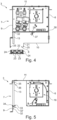
- the installer can pull the air filter 13, which is also replaceably or detachably attached to the housing 6, out of the housing through the air outlet 8, as in Figure 4 shown in a further sectional view.
- the air filter 13 is advantageously also held in the housing 6 by one or more locking elements.
- the pivot bearing 31 is also optionally assigned a condensate pan guide 37, which in particular forms a stop for the condensate pan 19, up to which the condensate pan 19 can be moved maximally in the direction of the pivot bearing 31.
- the condensate pan guide 37 is designed such that it limits the maximum tilt position of the condensate pan 19 or the pivoting path, thus ultimately defining the removal position of the condensate pan 19 by positively preventing further displacement of the condensate pan 19. This is also advantageous, for example, if the condensate pan 19 has a small width B2, which would allow pivoting of the condensate pan 19 in the area of the closed base 10, preventing such a movement.
- the air filter 13 is slidably mounted in the housing 6.
- the filter 13 can preferably be locked in the use position covering the air inlet 7 by one or more further locking elements in the housing 6.
- the air filter 13, as in Figure 5 shown in a further sectional view, can be arranged in a form-fitting manner on the air inlet 7 in a simple manner.
- the housing 6 has an air filter support 33 on the side wall 9, which is formed by a folded sheet metal, for example the housing wall 9.
- the support 33 forms in particular a Receiving pocket 34, into which the air filter 13 can be inserted from above, so that in the receiving pocket 34 it is safely prevented from slipping out of the air filter support 33.
- a guide plate 35 is arranged in the area of the ceiling wall 11 of the housing 6, which forms an insertion bevel 36 such that the air filter 13 can first be moved upwards along the insertion bevel 36 in the direction of the ceiling wall 11 for its assembly and is moved through the insertion bevel 36 with the upper end in the direction of the side wall 9, wherein the air filter 13 can be aligned at an angle to the side wall 9 in order to get past the air filter support 33.
- the lower end of the air filter 13 has overcome the air filter holder 33, it can be folded with the lower end towards the side wall 9 and then moved downwards to come to rest in the holder pocket 34.
- the guide plate 35 still holds the air filter 13 securely at its upper end in such a way that it covers the air inlet 7 and thus ensures that only filtered air can enter the housing 6 or the flow path through the housing 6.
- the air outlet 8 points vertically downwards
- the air outlet 8 is arranged or aligned parallel to the air inlet 7, so that a deflection of the air flow in the lower part of the housing 6 to the air outlet 8 is not necessary.
- the solution described above can also be achieved.
- the condensate tray 19 can be easily removed. Only the air filter 13 may have to be tilted further in order to reach the air outlet 8. In this case, a larger distance between the air filter 13 and the heat exchanger 14 may be necessary.
- the air filter 13 is designed as a foldable air filter 13, so that the distance between the air filter 13 and the heat exchanger 14 does not have to be increased.
- the invention is not limited to the illustrated arrangement of air inlet 7 and barrel outlet 8 relative to one another.
- an air supply connection 42 is arranged or designed to control the amount of fresh air in the to increase the room to be ventilated or air-conditioned.
- the fresh air is prepared in particular by a central air conditioning system and fed to device 3.
Landscapes
- Engineering & Computer Science (AREA)
- Chemical & Material Sciences (AREA)
- Combustion & Propulsion (AREA)
- Mechanical Engineering (AREA)
- General Engineering & Computer Science (AREA)
- Air Filters, Heat-Exchange Apparatuses, And Housings Of Air-Conditioning Units (AREA)
- Devices For Blowing Cold Air, Devices For Blowing Warm Air, And Means For Preventing Water Condensation In Air Conditioning Units (AREA)
Claims (13)
- Appareil de conditionnement d'air (3) permettant de ventiler et/ou climatiser un espace, dans lequel l'appareil de conditionnement d'air (3) présente un boîtier (6) présentant une entrée d'air (7) et une sortie d'air (8), dans lequel un trajet d'écoulement d'air, auquel sont associés un dispositif de transport d'air (16) d'une part et un filtre à air (13) associé à l'entrée d'air (7), un échangeur de chaleur (14) et une cuve à condensat (19) d'autre part, est formé à travers le boîtier (6) entre l'entrée d'air (7) et la sortie d'air (8), dans lequel le filtre à air (13) recouvre l'entrée d'air (7) de telle manière que seul l'air filtré grâce au filtre à air (13) pénètre dans le boîtier (6), dans lequel un diaphragme de sortie à fente (22) agencé au niveau du boîtier (6) et recouvrant la sortie d'air (8) est associé à la sortie d'air (8), dans lequel le diaphragme de sortie à fente (22) est fixé de manière amovible au boîtier (6), dans lequel le filtre à air (13) et la cuve à condensat (19) sont fixés de manière amovible dans le boîtier de manière à pouvoir être retirés du boîtier (6) en passant par la sortie d'air (8), dans lequel la sortie d'air (8) présente une largeur (B1), la cuve à condensat (19) présente une largeur (B2) et le filtre à air (13) présente une largeur (B3), dans lequel la largeur (B3) du filtre à air (13) est sensiblement inférieure à la largeur (B1) de la sortie d'air (8), et dans lequel la largeur (B2) de la cuve à condensat (19) est supérieure à la largeur (B1) de la sortie d'air (8), dans lequel la cuve à condensat (19) est montée pivotante dans le boîtier (6) grâce à un palier de pivotement (31) de manière à pouvoir pivoter entre une position d'utilisation associée à l'échangeur de chaleur (14) et une position de prélèvement, et dans lequel la cuve à condensat (19) peut, dans la position de prélèvement, être retirée du boîtier en passant par la sortie d'air (8), dans lequel le filtre à air (13) peut de manière préférée être retiré de la cuve à condensat (6) en passant devant la cuve à condensat par la sortie d'air (8).
- Appareil de conditionnement d'air selon la revendication 1, caractérisé en ce que le diaphragme de sortie à fente (22) est fixé au boîtier grâce à au moins un premier élément d'encliquetage (24) élastiquement déformable ou déplaçable.
- Appareil de conditionnement d'air selon l'une quelconque des revendications précédentes, caractérisé en ce que le au moins un premier élément d'encliquetage (24) est réalisé sous la forme d'un élément formant ressort à lame élastiquement déformable.
- Appareil de conditionnement d'air selon l'une quelconque des revendications précédentes, caractérisé en ce que le au moins un premier élément d'encliquetage (24) est retenu au niveau du diaphragme de sortie à fente (22).
- Appareil de conditionnement d'air selon l'une quelconque des revendications précédentes, caractérisé en ce que le boîtier (6) présente au moins une saillie d'encliquetage (25) coopérant avec le premier élément d'encliquetage (24) et/ou au moins un renfoncement coopérant avec le premier élément d'encliquetage (24).
- Appareil de conditionnement d'air selon l'une quelconque des revendications précédentes, caractérisé en ce que le palier de pivotement (31) est réalisé sous la forme d'un palier à roulement-insert formé d'une section de palier de la cuve à condensat et d'un orifice de palier (29) du boîtier (6).
- Appareil de conditionnement d'air selon l'une quelconque des revendications précédentes, caractérisé en ce qu'un guidage de cuve à condensat (37), destiné à la cuve à condensat (19) et limitant en particulier la course de pivotement de la cuve à condensat (19) en direction de la position de prélèvement, est associé au palier de pivotement (31).
- Appareil de conditionnement d'air selon l'une quelconque des revendications précédentes, caractérisé en ce qu'au moins un second élément d'encliquetage (32), au moyen duquel la cuve à condensat (19) peut être bloquée dans la position d'utilisation, est agencé au niveau du boîtier (6) et/ou au niveau de la cuve à condensat (19).
- Appareil de conditionnement d'air selon l'une quelconque des revendications précédentes, caractérisé en ce que la cuve à condensat (19) est agencée en dessous de l'échangeur de chaleur (14).
- Appareil de conditionnement d'air selon l'une quelconque des revendications précédentes, caractérisé en ce que le filtre à air (13) est agencé au-dessus de la sortie d'air (8) en amont de l'échangeur de chaleur (14).
- Appareil de conditionnement d'air selon l'une quelconque des revendications précédentes, caractérisé en ce que le boîtier (6) présente un logement de filtre à air (33) destiné au filtre à air (13) et au sein duquel le filtre à air (13) peut être inséré/enfiché.
- Appareil de conditionnement d'air selon l'une quelconque des revendications précédentes, caractérisé en ce que le logement de filtre à air (33) présente une poche de logement (34) permettant d'accueillir localement le filtre à air (13).
- Dispositif de ventilation (1) comprenant un appareil de conditionnement d'air (3) agencé dans un plafond (2) d'un espace et permettant de ventiler et/ou climatiser ledit espace, caractérisé par la conception d'appareil de conditionnement d'air (3) selon l'une quelconque des revendications 1 à 12.
Priority Applications (1)
| Application Number | Priority Date | Filing Date | Title |
|---|---|---|---|
| EP17160451.5A EP3372906B1 (fr) | 2017-03-10 | 2017-03-10 | Appareil de conditionnement d'air |
Applications Claiming Priority (1)
| Application Number | Priority Date | Filing Date | Title |
|---|---|---|---|
| EP17160451.5A EP3372906B1 (fr) | 2017-03-10 | 2017-03-10 | Appareil de conditionnement d'air |
Publications (2)
| Publication Number | Publication Date |
|---|---|
| EP3372906A1 EP3372906A1 (fr) | 2018-09-12 |
| EP3372906B1 true EP3372906B1 (fr) | 2024-07-31 |
Family
ID=58266989
Family Applications (1)
| Application Number | Title | Priority Date | Filing Date |
|---|---|---|---|
| EP17160451.5A Active EP3372906B1 (fr) | 2017-03-10 | 2017-03-10 | Appareil de conditionnement d'air |
Country Status (1)
| Country | Link |
|---|---|
| EP (1) | EP3372906B1 (fr) |
Families Citing this family (3)
| Publication number | Priority date | Publication date | Assignee | Title |
|---|---|---|---|---|
| DE102019104872A1 (de) * | 2019-02-26 | 2020-08-27 | Kampmann Gmbh | Klimatisierung von Räumen mit Quellluftzuführung und Temperierung |
| CN115264636B (zh) * | 2021-04-30 | 2025-02-14 | 宁波奥克斯电气有限公司 | 一种空调外壳和空调器 |
| CN115264638B (zh) * | 2021-04-30 | 2025-02-18 | 宁波奥克斯电气有限公司 | 一种空调壳体和空调器 |
Citations (1)
| Publication number | Priority date | Publication date | Assignee | Title |
|---|---|---|---|---|
| DE10014759A1 (de) * | 2000-03-24 | 2001-10-04 | Daldrop & Dr Ing Huber Gmbh & | Deckenelement für Reinräume |
Family Cites Families (2)
| Publication number | Priority date | Publication date | Assignee | Title |
|---|---|---|---|---|
| DE202011107886U1 (de) * | 2011-11-15 | 2013-02-18 | Max Blank Gmbh | Lüftungsgitter-Einsetzzargen-Anordnung |
| DE102015006762A1 (de) * | 2015-06-01 | 2016-12-15 | Kampmann Gmbh | Unterflurklimatisierungsvorrichtung |
-
2017
- 2017-03-10 EP EP17160451.5A patent/EP3372906B1/fr active Active
Patent Citations (1)
| Publication number | Priority date | Publication date | Assignee | Title |
|---|---|---|---|---|
| DE10014759A1 (de) * | 2000-03-24 | 2001-10-04 | Daldrop & Dr Ing Huber Gmbh & | Deckenelement für Reinräume |
Also Published As
| Publication number | Publication date |
|---|---|
| EP3372906A1 (fr) | 2018-09-12 |
Similar Documents
| Publication | Publication Date | Title |
|---|---|---|
| EP1944553B1 (fr) | Dispositif d'aspiration de vapeurs de cuisson doté d'un canal plat à air | |
| DE102009025038B4 (de) | Kochdunst-Eintrittsvorrichtung mit abnehmbarer deckelförmiger Verschließeinrichtung | |
| EP2561738B1 (fr) | Unité filtre pour une armoire de distribution | |
| DE102008033792B4 (de) | Umluftmodul und Dunstabzugsvorrichtung | |
| EP3475622B1 (fr) | Système de ventilation à courant descendant avec un insert | |
| EP3551938B1 (fr) | Appareil ménager | |
| DE102017121367B4 (de) | Dunstabzug zum Abzug von auf einem Kochfeld erzeugter Abluft in vertikal unterhalb einer Kochfeldebene weisender Richtung | |
| EP3401606B1 (fr) | Agencement de conduite d'air pour un dispositif de hotte aspirante à tirage descendant, socle de meuble et dispositif de hotte aspirante à tirage descendant correspondant | |
| DE19645096A1 (de) | Luftreinigungsgerät | |
| EP1909548A1 (fr) | Aérateur de filtre | |
| DE202009008286U1 (de) | Kochdunst-Eintrittsvorrichtung mit abnehmbarer deckelförmiger Verschließeinrichtung | |
| EP1134501A1 (fr) | Hotte aspirante de buée | |
| EP3372906B1 (fr) | Appareil de conditionnement d'air | |
| EP1832818B1 (fr) | Installation d'aération | |
| EP2772695B1 (fr) | Hotte aspirante | |
| EP2286153B1 (fr) | Déflecteur d'air | |
| DE102005030038B4 (de) | Kochfeldabzugsvorrichtung | |
| EP2615383B1 (fr) | Hotte aspirante | |
| EP2829808B1 (fr) | Hotte aspirante | |
| DE20122340U1 (de) | Dunstabzugshaube | |
| EP2708827B1 (fr) | Entrée ou sortie d'air et système de ventilation doté de celle-ci | |
| DE112011101234B4 (de) | Kühlregal und Verfahren zum Betrieb eines Kühlregals | |
| EP2554915B1 (fr) | Hotte aspirante avec support de filtre et élément filtrant d'odeurs | |
| DE7811284U1 (de) | Umbaubare Küchendunst-Abzugsvorrichtung | |
| DE29906375U1 (de) | Lüftungsanordnung für in Gebäuden untergebrachten Räumen |
Legal Events
| Date | Code | Title | Description |
|---|---|---|---|
| PUAI | Public reference made under article 153(3) epc to a published international application that has entered the european phase |
Free format text: ORIGINAL CODE: 0009012 |
|
| STAA | Information on the status of an ep patent application or granted ep patent |
Free format text: STATUS: THE APPLICATION HAS BEEN PUBLISHED |
|
| AK | Designated contracting states |
Kind code of ref document: A1 Designated state(s): AL AT BE BG CH CY CZ DE DK EE ES FI FR GB GR HR HU IE IS IT LI LT LU LV MC MK MT NL NO PL PT RO RS SE SI SK SM TR |
|
| AX | Request for extension of the european patent |
Extension state: BA ME |
|
| STAA | Information on the status of an ep patent application or granted ep patent |
Free format text: STATUS: REQUEST FOR EXAMINATION WAS MADE |
|
| 17P | Request for examination filed |
Effective date: 20190312 |
|
| RBV | Designated contracting states (corrected) |
Designated state(s): AL AT BE BG CH CY CZ DE DK EE ES FI FR GB GR HR HU IE IS IT LI LT LU LV MC MK MT NL NO PL PT RO RS SE SI SK SM TR |
|
| STAA | Information on the status of an ep patent application or granted ep patent |
Free format text: STATUS: EXAMINATION IS IN PROGRESS |
|
| 17Q | First examination report despatched |
Effective date: 20201125 |
|
| REG | Reference to a national code |
Ref country code: DE Ref legal event code: R079 Free format text: PREVIOUS MAIN CLASS: F24F0001000000 Ipc: F24F0001004700 Ref country code: DE Ref legal event code: R079 Ref document number: 502017016295 Country of ref document: DE Free format text: PREVIOUS MAIN CLASS: F24F0001000000 Ipc: F24F0001004700 |
|
| GRAP | Despatch of communication of intention to grant a patent |
Free format text: ORIGINAL CODE: EPIDOSNIGR1 |
|
| STAA | Information on the status of an ep patent application or granted ep patent |
Free format text: STATUS: GRANT OF PATENT IS INTENDED |
|
| RIC1 | Information provided on ipc code assigned before grant |
Ipc: F24F 13/08 20060101ALI20240222BHEP Ipc: F24F 1/0073 20190101ALI20240222BHEP Ipc: F24F 1/0047 20190101AFI20240222BHEP Ipc: F24F 13/22 20060101ALI20240222BHEP Ipc: F24F 1/0011 20190101ALI20240222BHEP |
|
| INTG | Intention to grant announced |
Effective date: 20240311 |
|
| GRAS | Grant fee paid |
Free format text: ORIGINAL CODE: EPIDOSNIGR3 |
|
| GRAA | (expected) grant |
Free format text: ORIGINAL CODE: 0009210 |
|
| STAA | Information on the status of an ep patent application or granted ep patent |
Free format text: STATUS: THE PATENT HAS BEEN GRANTED |
|
| AK | Designated contracting states |
Kind code of ref document: B1 Designated state(s): AL AT BE BG CH CY CZ DE DK EE ES FI FR GB GR HR HU IE IS IT LI LT LU LV MC MK MT NL NO PL PT RO RS SE SI SK SM TR |
|
| REG | Reference to a national code |
Ref country code: CH Ref legal event code: EP Ref country code: GB Ref legal event code: FG4D Free format text: NOT ENGLISH |
|
| REG | Reference to a national code |
Ref country code: DE Ref legal event code: R096 Ref document number: 502017016295 Country of ref document: DE |
|
| REG | Reference to a national code |
Ref country code: IE Ref legal event code: FG4D Free format text: LANGUAGE OF EP DOCUMENT: GERMAN |
|
| REG | Reference to a national code |
Ref country code: NL Ref legal event code: FP |
|
| REG | Reference to a national code |
Ref country code: LT Ref legal event code: MG9D |
|
| PG25 | Lapsed in a contracting state [announced via postgrant information from national office to epo] |
Ref country code: PT Free format text: LAPSE BECAUSE OF FAILURE TO SUBMIT A TRANSLATION OF THE DESCRIPTION OR TO PAY THE FEE WITHIN THE PRESCRIBED TIME-LIMIT Effective date: 20241202 |
|
| PG25 | Lapsed in a contracting state [announced via postgrant information from national office to epo] |
Ref country code: PT Free format text: LAPSE BECAUSE OF FAILURE TO SUBMIT A TRANSLATION OF THE DESCRIPTION OR TO PAY THE FEE WITHIN THE PRESCRIBED TIME-LIMIT Effective date: 20241202 |
|
| PG25 | Lapsed in a contracting state [announced via postgrant information from national office to epo] |
Ref country code: NO Free format text: LAPSE BECAUSE OF FAILURE TO SUBMIT A TRANSLATION OF THE DESCRIPTION OR TO PAY THE FEE WITHIN THE PRESCRIBED TIME-LIMIT Effective date: 20241031 |
|
| PG25 | Lapsed in a contracting state [announced via postgrant information from national office to epo] |
Ref country code: FI Free format text: LAPSE BECAUSE OF FAILURE TO SUBMIT A TRANSLATION OF THE DESCRIPTION OR TO PAY THE FEE WITHIN THE PRESCRIBED TIME-LIMIT Effective date: 20240731 Ref country code: PL Free format text: LAPSE BECAUSE OF FAILURE TO SUBMIT A TRANSLATION OF THE DESCRIPTION OR TO PAY THE FEE WITHIN THE PRESCRIBED TIME-LIMIT Effective date: 20240731 Ref country code: GR Free format text: LAPSE BECAUSE OF FAILURE TO SUBMIT A TRANSLATION OF THE DESCRIPTION OR TO PAY THE FEE WITHIN THE PRESCRIBED TIME-LIMIT Effective date: 20241101 |
|
| PG25 | Lapsed in a contracting state [announced via postgrant information from national office to epo] |
Ref country code: BG Free format text: LAPSE BECAUSE OF FAILURE TO SUBMIT A TRANSLATION OF THE DESCRIPTION OR TO PAY THE FEE WITHIN THE PRESCRIBED TIME-LIMIT Effective date: 20240731 |
|
| PG25 | Lapsed in a contracting state [announced via postgrant information from national office to epo] |
Ref country code: LV Free format text: LAPSE BECAUSE OF FAILURE TO SUBMIT A TRANSLATION OF THE DESCRIPTION OR TO PAY THE FEE WITHIN THE PRESCRIBED TIME-LIMIT Effective date: 20240731 |
|
| PG25 | Lapsed in a contracting state [announced via postgrant information from national office to epo] |
Ref country code: IS Free format text: LAPSE BECAUSE OF FAILURE TO SUBMIT A TRANSLATION OF THE DESCRIPTION OR TO PAY THE FEE WITHIN THE PRESCRIBED TIME-LIMIT Effective date: 20241130 |
|
| PG25 | Lapsed in a contracting state [announced via postgrant information from national office to epo] |
Ref country code: HR Free format text: LAPSE BECAUSE OF FAILURE TO SUBMIT A TRANSLATION OF THE DESCRIPTION OR TO PAY THE FEE WITHIN THE PRESCRIBED TIME-LIMIT Effective date: 20240731 |
|
| PG25 | Lapsed in a contracting state [announced via postgrant information from national office to epo] |
Ref country code: ES Free format text: LAPSE BECAUSE OF FAILURE TO SUBMIT A TRANSLATION OF THE DESCRIPTION OR TO PAY THE FEE WITHIN THE PRESCRIBED TIME-LIMIT Effective date: 20240731 Ref country code: RS Free format text: LAPSE BECAUSE OF FAILURE TO SUBMIT A TRANSLATION OF THE DESCRIPTION OR TO PAY THE FEE WITHIN THE PRESCRIBED TIME-LIMIT Effective date: 20241031 |
|
| PG25 | Lapsed in a contracting state [announced via postgrant information from national office to epo] |
Ref country code: RS Free format text: LAPSE BECAUSE OF FAILURE TO SUBMIT A TRANSLATION OF THE DESCRIPTION OR TO PAY THE FEE WITHIN THE PRESCRIBED TIME-LIMIT Effective date: 20241031 Ref country code: PL Free format text: LAPSE BECAUSE OF FAILURE TO SUBMIT A TRANSLATION OF THE DESCRIPTION OR TO PAY THE FEE WITHIN THE PRESCRIBED TIME-LIMIT Effective date: 20240731 Ref country code: NO Free format text: LAPSE BECAUSE OF FAILURE TO SUBMIT A TRANSLATION OF THE DESCRIPTION OR TO PAY THE FEE WITHIN THE PRESCRIBED TIME-LIMIT Effective date: 20241031 Ref country code: LV Free format text: LAPSE BECAUSE OF FAILURE TO SUBMIT A TRANSLATION OF THE DESCRIPTION OR TO PAY THE FEE WITHIN THE PRESCRIBED TIME-LIMIT Effective date: 20240731 Ref country code: IS Free format text: LAPSE BECAUSE OF FAILURE TO SUBMIT A TRANSLATION OF THE DESCRIPTION OR TO PAY THE FEE WITHIN THE PRESCRIBED TIME-LIMIT Effective date: 20241130 Ref country code: HR Free format text: LAPSE BECAUSE OF FAILURE TO SUBMIT A TRANSLATION OF THE DESCRIPTION OR TO PAY THE FEE WITHIN THE PRESCRIBED TIME-LIMIT Effective date: 20240731 Ref country code: GR Free format text: LAPSE BECAUSE OF FAILURE TO SUBMIT A TRANSLATION OF THE DESCRIPTION OR TO PAY THE FEE WITHIN THE PRESCRIBED TIME-LIMIT Effective date: 20241101 Ref country code: FI Free format text: LAPSE BECAUSE OF FAILURE TO SUBMIT A TRANSLATION OF THE DESCRIPTION OR TO PAY THE FEE WITHIN THE PRESCRIBED TIME-LIMIT Effective date: 20240731 Ref country code: ES Free format text: LAPSE BECAUSE OF FAILURE TO SUBMIT A TRANSLATION OF THE DESCRIPTION OR TO PAY THE FEE WITHIN THE PRESCRIBED TIME-LIMIT Effective date: 20240731 Ref country code: BG Free format text: LAPSE BECAUSE OF FAILURE TO SUBMIT A TRANSLATION OF THE DESCRIPTION OR TO PAY THE FEE WITHIN THE PRESCRIBED TIME-LIMIT Effective date: 20240731 |
|
| PGFP | Annual fee paid to national office [announced via postgrant information from national office to epo] |
Ref country code: DE Payment date: 20250327 Year of fee payment: 9 |
|
| PG25 | Lapsed in a contracting state [announced via postgrant information from national office to epo] |
Ref country code: DK Free format text: LAPSE BECAUSE OF FAILURE TO SUBMIT A TRANSLATION OF THE DESCRIPTION OR TO PAY THE FEE WITHIN THE PRESCRIBED TIME-LIMIT Effective date: 20240731 Ref country code: SM Free format text: LAPSE BECAUSE OF FAILURE TO SUBMIT A TRANSLATION OF THE DESCRIPTION OR TO PAY THE FEE WITHIN THE PRESCRIBED TIME-LIMIT Effective date: 20240731 Ref country code: RO Free format text: LAPSE BECAUSE OF FAILURE TO SUBMIT A TRANSLATION OF THE DESCRIPTION OR TO PAY THE FEE WITHIN THE PRESCRIBED TIME-LIMIT Effective date: 20240731 |
|
| PG25 | Lapsed in a contracting state [announced via postgrant information from national office to epo] |
Ref country code: EE Free format text: LAPSE BECAUSE OF FAILURE TO SUBMIT A TRANSLATION OF THE DESCRIPTION OR TO PAY THE FEE WITHIN THE PRESCRIBED TIME-LIMIT Effective date: 20240731 |
|
| PG25 | Lapsed in a contracting state [announced via postgrant information from national office to epo] |
Ref country code: CZ Free format text: LAPSE BECAUSE OF FAILURE TO SUBMIT A TRANSLATION OF THE DESCRIPTION OR TO PAY THE FEE WITHIN THE PRESCRIBED TIME-LIMIT Effective date: 20240731 |
|
| PG25 | Lapsed in a contracting state [announced via postgrant information from national office to epo] |
Ref country code: SK Free format text: LAPSE BECAUSE OF FAILURE TO SUBMIT A TRANSLATION OF THE DESCRIPTION OR TO PAY THE FEE WITHIN THE PRESCRIBED TIME-LIMIT Effective date: 20240731 |
|
| REG | Reference to a national code |
Ref country code: DE Ref legal event code: R097 Ref document number: 502017016295 Country of ref document: DE |
|
| PLBE | No opposition filed within time limit |
Free format text: ORIGINAL CODE: 0009261 |
|
| STAA | Information on the status of an ep patent application or granted ep patent |
Free format text: STATUS: NO OPPOSITION FILED WITHIN TIME LIMIT |
|
| 26N | No opposition filed |
Effective date: 20250501 |
|
| PGFP | Annual fee paid to national office [announced via postgrant information from national office to epo] |
Ref country code: CH Payment date: 20250401 Year of fee payment: 9 |
|
| PG25 | Lapsed in a contracting state [announced via postgrant information from national office to epo] |
Ref country code: SE Free format text: LAPSE BECAUSE OF FAILURE TO SUBMIT A TRANSLATION OF THE DESCRIPTION OR TO PAY THE FEE WITHIN THE PRESCRIBED TIME-LIMIT Effective date: 20240731 |
|
| PG25 | Lapsed in a contracting state [announced via postgrant information from national office to epo] |
Ref country code: MC Free format text: LAPSE BECAUSE OF FAILURE TO SUBMIT A TRANSLATION OF THE DESCRIPTION OR TO PAY THE FEE WITHIN THE PRESCRIBED TIME-LIMIT Effective date: 20240731 |
|
| PG25 | Lapsed in a contracting state [announced via postgrant information from national office to epo] |
Ref country code: IE Free format text: LAPSE BECAUSE OF NON-PAYMENT OF DUE FEES Effective date: 20250310 |
|
| REG | Reference to a national code |
Ref country code: CH Ref legal event code: U11 Free format text: ST27 STATUS EVENT CODE: U-0-0-U10-U11 (AS PROVIDED BY THE NATIONAL OFFICE) Effective date: 20260401 |
|
| PGFP | Annual fee paid to national office [announced via postgrant information from national office to epo] |
Ref country code: GB Payment date: 20260324 Year of fee payment: 10 |
|
| PGFP | Annual fee paid to national office [announced via postgrant information from national office to epo] |
Ref country code: AT Payment date: 20260320 Year of fee payment: 10 |
|
| PGFP | Annual fee paid to national office [announced via postgrant information from national office to epo] |
Ref country code: LU Payment date: 20260319 Year of fee payment: 10 Ref country code: BE Payment date: 20260319 Year of fee payment: 10 Ref country code: IT Payment date: 20260319 Year of fee payment: 10 |
|
| PGFP | Annual fee paid to national office [announced via postgrant information from national office to epo] |
Ref country code: NL Payment date: 20260319 Year of fee payment: 10 |
|
| PGFP | Annual fee paid to national office [announced via postgrant information from national office to epo] |
Ref country code: FR Payment date: 20260320 Year of fee payment: 10 |