EP3373028B1 - Signalinterferenzvermeidungssystem für einen frequenzmodulierten dauerstrichradar-höhenmesser - Google Patents
Signalinterferenzvermeidungssystem für einen frequenzmodulierten dauerstrichradar-höhenmesser Download PDFInfo
- Publication number
- EP3373028B1 EP3373028B1 EP18160054.5A EP18160054A EP3373028B1 EP 3373028 B1 EP3373028 B1 EP 3373028B1 EP 18160054 A EP18160054 A EP 18160054A EP 3373028 B1 EP3373028 B1 EP 3373028B1
- Authority
- EP
- European Patent Office
- Prior art keywords
- frequency
- ramp
- signal
- stop
- fmcw
- Prior art date
- Legal status (The legal status is an assumption and is not a legal conclusion. Google has not performed a legal analysis and makes no representation as to the accuracy of the status listed.)
- Active
Links
Images
Classifications
-
- G—PHYSICS
- G01—MEASURING; TESTING
- G01S—RADIO DIRECTION-FINDING; RADIO NAVIGATION; DETERMINING DISTANCE OR VELOCITY BY USE OF RADIO WAVES; LOCATING OR PRESENCE-DETECTING BY USE OF THE REFLECTION OR RERADIATION OF RADIO WAVES; ANALOGOUS ARRANGEMENTS USING OTHER WAVES
- G01S7/00—Details of systems according to groups G01S13/00, G01S15/00, G01S17/00
- G01S7/02—Details of systems according to groups G01S13/00, G01S15/00, G01S17/00 of systems according to group G01S13/00
- G01S7/36—Means for anti-jamming, e.g. ECCM, i.e. electronic counter-counter measures
-
- G—PHYSICS
- G01—MEASURING; TESTING
- G01S—RADIO DIRECTION-FINDING; RADIO NAVIGATION; DETERMINING DISTANCE OR VELOCITY BY USE OF RADIO WAVES; LOCATING OR PRESENCE-DETECTING BY USE OF THE REFLECTION OR RERADIATION OF RADIO WAVES; ANALOGOUS ARRANGEMENTS USING OTHER WAVES
- G01S7/00—Details of systems according to groups G01S13/00, G01S15/00, G01S17/00
- G01S7/02—Details of systems according to groups G01S13/00, G01S15/00, G01S17/00 of systems according to group G01S13/00
- G01S7/023—Interference mitigation, e.g. reducing or avoiding non-intentional interference with other HF-transmitters, base station transmitters for mobile communication or other radar systems, e.g. using electro-magnetic interference [EMI] reduction techniques
-
- G—PHYSICS
- G01—MEASURING; TESTING
- G01S—RADIO DIRECTION-FINDING; RADIO NAVIGATION; DETERMINING DISTANCE OR VELOCITY BY USE OF RADIO WAVES; LOCATING OR PRESENCE-DETECTING BY USE OF THE REFLECTION OR RERADIATION OF RADIO WAVES; ANALOGOUS ARRANGEMENTS USING OTHER WAVES
- G01S13/00—Systems using the reflection or reradiation of radio waves, e.g. radar systems; Analogous systems using reflection or reradiation of waves whose nature or wavelength is irrelevant or unspecified
- G01S13/02—Systems using reflection of radio waves, e.g. primary radar systems; Analogous systems
- G01S13/06—Systems determining position data of a target
- G01S13/08—Systems for measuring distance only
- G01S13/32—Systems for measuring distance only using transmission of continuous waves, whether amplitude-, frequency-, or phase-modulated, or unmodulated
- G01S13/34—Systems for measuring distance only using transmission of continuous waves, whether amplitude-, frequency-, or phase-modulated, or unmodulated using transmission of continuous, frequency-modulated waves while heterodyning the received signal, or a signal derived therefrom, with a locally-generated signal related to the contemporaneously transmitted signal
- G01S13/343—Systems for measuring distance only using transmission of continuous waves, whether amplitude-, frequency-, or phase-modulated, or unmodulated using transmission of continuous, frequency-modulated waves while heterodyning the received signal, or a signal derived therefrom, with a locally-generated signal related to the contemporaneously transmitted signal using sawtooth modulation
-
- G—PHYSICS
- G01—MEASURING; TESTING
- G01S—RADIO DIRECTION-FINDING; RADIO NAVIGATION; DETERMINING DISTANCE OR VELOCITY BY USE OF RADIO WAVES; LOCATING OR PRESENCE-DETECTING BY USE OF THE REFLECTION OR RERADIATION OF RADIO WAVES; ANALOGOUS ARRANGEMENTS USING OTHER WAVES
- G01S13/00—Systems using the reflection or reradiation of radio waves, e.g. radar systems; Analogous systems using reflection or reradiation of waves whose nature or wavelength is irrelevant or unspecified
- G01S13/02—Systems using reflection of radio waves, e.g. primary radar systems; Analogous systems
- G01S13/06—Systems determining position data of a target
- G01S13/08—Systems for measuring distance only
- G01S13/32—Systems for measuring distance only using transmission of continuous waves, whether amplitude-, frequency-, or phase-modulated, or unmodulated
- G01S13/34—Systems for measuring distance only using transmission of continuous waves, whether amplitude-, frequency-, or phase-modulated, or unmodulated using transmission of continuous, frequency-modulated waves while heterodyning the received signal, or a signal derived therefrom, with a locally-generated signal related to the contemporaneously transmitted signal
- G01S13/345—Systems for measuring distance only using transmission of continuous waves, whether amplitude-, frequency-, or phase-modulated, or unmodulated using transmission of continuous, frequency-modulated waves while heterodyning the received signal, or a signal derived therefrom, with a locally-generated signal related to the contemporaneously transmitted signal using triangular modulation
-
- G—PHYSICS
- G01—MEASURING; TESTING
- G01S—RADIO DIRECTION-FINDING; RADIO NAVIGATION; DETERMINING DISTANCE OR VELOCITY BY USE OF RADIO WAVES; LOCATING OR PRESENCE-DETECTING BY USE OF THE REFLECTION OR RERADIATION OF RADIO WAVES; ANALOGOUS ARRANGEMENTS USING OTHER WAVES
- G01S13/00—Systems using the reflection or reradiation of radio waves, e.g. radar systems; Analogous systems using reflection or reradiation of waves whose nature or wavelength is irrelevant or unspecified
- G01S13/88—Radar or analogous systems specially adapted for specific applications
- G01S13/882—Radar or analogous systems specially adapted for specific applications for altimeters
-
- G—PHYSICS
- G01—MEASURING; TESTING
- G01S—RADIO DIRECTION-FINDING; RADIO NAVIGATION; DETERMINING DISTANCE OR VELOCITY BY USE OF RADIO WAVES; LOCATING OR PRESENCE-DETECTING BY USE OF THE REFLECTION OR RERADIATION OF RADIO WAVES; ANALOGOUS ARRANGEMENTS USING OTHER WAVES
- G01S7/00—Details of systems according to groups G01S13/00, G01S15/00, G01S17/00
- G01S7/02—Details of systems according to groups G01S13/00, G01S15/00, G01S17/00 of systems according to group G01S13/00
- G01S7/023—Interference mitigation, e.g. reducing or avoiding non-intentional interference with other HF-transmitters, base station transmitters for mobile communication or other radar systems, e.g. using electro-magnetic interference [EMI] reduction techniques
- G01S7/0232—Avoidance by frequency multiplex
-
- G—PHYSICS
- G01—MEASURING; TESTING
- G01S—RADIO DIRECTION-FINDING; RADIO NAVIGATION; DETERMINING DISTANCE OR VELOCITY BY USE OF RADIO WAVES; LOCATING OR PRESENCE-DETECTING BY USE OF THE REFLECTION OR RERADIATION OF RADIO WAVES; ANALOGOUS ARRANGEMENTS USING OTHER WAVES
- G01S7/00—Details of systems according to groups G01S13/00, G01S15/00, G01S17/00
- G01S7/02—Details of systems according to groups G01S13/00, G01S15/00, G01S17/00 of systems according to group G01S13/00
- G01S7/023—Interference mitigation, e.g. reducing or avoiding non-intentional interference with other HF-transmitters, base station transmitters for mobile communication or other radar systems, e.g. using electro-magnetic interference [EMI] reduction techniques
- G01S7/0234—Avoidance by code multiplex
-
- G—PHYSICS
- G01—MEASURING; TESTING
- G01S—RADIO DIRECTION-FINDING; RADIO NAVIGATION; DETERMINING DISTANCE OR VELOCITY BY USE OF RADIO WAVES; LOCATING OR PRESENCE-DETECTING BY USE OF THE REFLECTION OR RERADIATION OF RADIO WAVES; ANALOGOUS ARRANGEMENTS USING OTHER WAVES
- G01S13/00—Systems using the reflection or reradiation of radio waves, e.g. radar systems; Analogous systems using reflection or reradiation of waves whose nature or wavelength is irrelevant or unspecified
- G01S13/87—Combinations of radar systems, e.g. primary radar and secondary radar
Definitions
- a radar altimeter Successful operation of a radar altimeter requires that the device is able to detect and track the reflected return of its own transmitted radio frequency (RF) signal, without being negatively impacted by interference signals in the same RF band.
- This in-band interference may cause the victim altimeter to track the false signals and report erroneous altitudes, or to lose track of its own signal and "break lock.” Both of these failure modes are problematic, and in safety-critical applications such as final approach guidance or terrain avoidance, they are highly dangerous as well.
- the most common sources of in-band interference signals are other radar altimeters. In certain applications, multiple radar altimeters of the same type may be installed on the same aircraft for redundancy, leading to potential issues of mutual interference between the devices. In addition, the radar altimeters installed on other aircraft, which may be of the same type or a different type, may pose a threat under certain circumstances, especially in high-traffic airspace such as in the immediate vicinity of busy airports.
- Patent document number US2003/001772A1 describes a radar detection process, which includes computing a derivative of an FFT output signal to detect an object within a specified detection zone. A zero crossing in the second derivative of the FFT output signal indicates the presence of an object. The range of the object is determined as a function of the frequency at which the zero crossing occurs. Also described is a detection table containing indicators of the presence or absence of an object within a respective radar beam and processing cycle. At least two such indicators are combined in order to detect the presence of an object within the detection zone.
- Patent document number US2017/023662A1 describes a frequency-modulated continuous-wave radar processing system and method, which defines a linear frequency ramp signal.
- the linear ramp signal is divided into a plurality of time sections. The sections of the linear ramp signal are rearranged in time such that the plurality of sections define a transmit control signal different than the linear ramp signal.
- a radar transmission signal is generated having a frequency varying with time according to the transmit control signal, and the radar transmission signal is transmitted into the region of interest.
- An intermediate frequency (IF) signal is generated using the radar transmission signal and radar receive signals received from the region of interest, a frequency of the IF signal being a difference between the frequency of the radar transmission signal and a frequency of the radar receive signals.
- the IF signal is low-pass filtered. Radar processing is performed on the low-pass-filtered IF signal.
- Patent document number EP2006709A1 describes an object ranging system which operates by transmitting alternating up and down frequency sweeps which have randomly distributed slopes as a result of random selection of local frequency peaks and valleys according to predetermined probability tables, and determining the beat frequency obtained when combining the transmitted signal with its reflection from an object.
- Patent document number EP2653887A1 describes a system which has a radio wave generator for generating a frequency modulated radio wave by a modulation signal comprising a repetition of sequences of variation of frequency. The successive sequences are separated by a waiting level with variable duration.
- An identifier obtaining module distinguishes the system from any other radio altimetry installation.
- a generation module selects a configuration of the waiting level for the modulation signal according to the identifier, where the configuration of the waiting level defines variable durations of the waiting level.
- EP2863239A1 discloses a method for operating a radar altimeter.
- the method includes transmitting a radar signal at a first frequency, ramping the frequency of the radar signal from the first frequency to a second frequency, and transmitting the radar signal at the second frequency.
- the reflections can be processed by determining an approximate distance to a target based reflections of the frequency ramp and the approximate distance can be refined based on a phase difference between a reflection of the radar signal transmitted at the first frequency and a reflection of the radar signal transmitted at the second frequency.
- Embodiments implement at least one pseudorandom noise sequence generator to generate an integer value that is used as an index to at least one of start and stop frequency values stored in a frequency table.
- a radar signal is generated with transmit frames that are each formed based on a then current indexed start or stop frequency value.
- a signal interference prevention system for a frequency modulated continuous wave (FMCW) radar altimeter includes a frequency synthesizer, at least one memory and a field-programmable gate array (FPGA).
- the frequency synthesizer is used to generate FMCW ramps in a radio frequency (RF) signal used in the FMCW radar altimeter.
- RF radio frequency
- a ramp rate of the frequency synthesizer is fixed to provide a constant radar range of resolution.
- a transmit frame time of the frequency synthesizer is fixed to provide simplified signal processing in the FMCW radar altimeter.
- At least one frequency table is stored in the at least one memory.
- the FPGA is configured to implement at least one pseudorandom noise sequence generator to generate an integer value that is used as an index into the at least one frequency table in selecting a start frequency of the FMCW ramp for a current frame of the radio frequency (RF) signal.
- the FPGA is further configured to use a start frequency of a next transmit frame as a stop frequency.
- the at least one pseudorandom noise sequence generator is clocked one frame ahead of the frequency synthesizer so that the start and stop frequency may be configured at the beginning of each frame.
- a radar altimeter with an interference prevention system includes at least one antenna, a transmitter, a receiver, a signal processor and a signal generator.
- the at least one antenna is used to transmit and receive frequency modulated signals.
- the transmitter and the receiver are in communication with the at least one antenna.
- the signal processor is in communication with the receiver.
- the signal processor is configured to process received signals to determine ranging information.
- the signal generator is configured to generate the frequency modulated signals.
- the signal generator is in communication with the at least one transmitter.
- the signal generator includes at least one pseudorandom noise sequence generator, at least one memory, at least one frequency synthesizer and at least one controller.
- the at least one pseudorandom noise sequence generator is configured to generate integer values from a fixed time base signal.
- the at least one memory is configured to store at least one of start frequencies and stop frequencies.
- the frequency synthesizer is configured to generate frequency modulated continuous wave (FMCW) ramps in transmit frames of the frequency modulated signal.
- the at least one controller is configured to use the generated integer values from the at least one pseudorandom noise sequence generator as indexes to the at least one of start frequencies and stop frequencies stored in the at least one memory.
- the controller is further configured to cause the frequency synthesizer to generate the FMCW ramps based on the at least one of the start frequencies and stop frequencies indexed from the at least one memory.
- a method of operating an interference prevention system in a radar altimeter includes generating integer values with at least one pseudorandom noise sequence generator.
- the generated integer values are used as indexes to select at least one of start frequencies and stop frequencies from at least one frequency table for frequency modulated continuous wave (FMCW) ramps for a generated radar signal.
- the selected at least one of the start frequencies and the stop frequencies is provided to a frequency synthesizer.
- the at least one of start frequencies and the stop frequencies are used in generating transmit frames of the radar signal with the frequency synthesizer.
- Embodiments of the present invention provide a system that pseudorandomly varies parameters of frequency-modulated continuous wave (FMCW) ramps, either by changing the timing of the ramps or the frequencies of the ramps.
- FMCW frequency-modulated continuous wave
- Embodiments provide nearly optimal mutual interference performance for the Single Antenna Radar Altimeter (SARA), with only very minimal impact to the design of both the device hardware and software. Although the implementation is specific to SARA, the methods are easily applicable to other FMCW radar altimeters.
- SARA Single Antenna Radar Altimeter
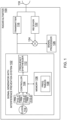
- a simplified FMCW radar altimeter 100 block diagram including a signal generator with signal interference prevention system 102 of an embodiment.
- the signal generator with signal interference prevention system 102 provides a radio frequency (RF) signal used by the radar altimeter 100.
- the radar altimeter 100 further include transmitter 116 that transmits the radar signal from the signal generator with signal interference prevention system 102 via antenna 118.
- a reflected radar return signal is received back through antenna 118 and receiver 122.
- the reflected radar return signal is combined with a sample of the generated radar signal from the signal generator with signal interference prevention system 102 at mixer 124.
- the combined signal is provided to a signal processor 126 that provides ranging results based on reflected radar return signals and the generated radar signals from the signal generator with signal interference prevention system 102.
- Only one antenna 118 is illustrated in Figure 1 , other embodiments may include a separate transmit antenna and a receive antenna.
- the signal generator with signal interference prevention system 102 includes a frequency synthesizer 112.
- frequency synthesizer 112 generates FMCW ramps in transmit frames under the control of controller 104 to generate the radar signal.
- a ramp rate of the frequency synthesizer 112 may be fixed to provide a constant range resolution.
- a transmit frame time of the frequency synthesizer 112 may be fixed to provide simplified signal processing in the signal processor 126 of the radar altimeter 100.
- the signal generator with signal interference prevention system 102 further includes at least one pseudorandom noise (PRN) sequence generator (generally designated as 110), which in this example embodiment includes three PRN sequence generators 110-1 through 110-3 which are in communication with a clock 114 to receive a fixed time base signal.
- PRN pseudorandom noise
- a memory 106 Stored within the memory 106 are frequency tables 108.
- the frequency tables 108 include at least one of start frequencies and stop frequencies.
- controller 104 may include any one or more of a processor, microprocessor, a digital signal processor (DSP), an application specific integrated circuit (ASIC), a field-programmable gate array (FPGA), or equivalent discrete or integrated logic circuitry.
- controller 104 may include multiple components, such as any combination of one or more microprocessors, one or more controllers, one or more DSPs, one or more ASICs, one or more FPGAs, as well as other discrete or integrated logic circuitry.
- Embodiments using at least one FPGA 104 are particularly efficient in that linear feedback shift registers of the FPGA 104 can be implemented resulting in a minimal use of resources as mentioned above.
- the frequency tables 108 may contain only a few elements in some embodiments and thus can be stored directly in the FPGA 104 fabric rather than an external memory.
- the functions attributed to the controller 104 herein may be embodied as software, firmware, hardware or any combination thereof.
- the controller may be part of a system controller or a component controller.
- the memory 106 may include computer-readable operating instructions that, when executed by the controller 104 provide functions of the signal generator. Such functions may include the functions of the signal generator with signal interference prevention system 102 described below.
- the computer readable instructions may be encoded within the memory.
- Memory 106 may comprise computer readable storage media including any volatile, nonvolatile, magnetic, optical, or electrical media, such as, but not limited to, a random access memory (RAM), read-only memory (ROM), non-volatile RAM (NVRAM), electrically-erasable programmable ROM (EEPROM), flash memory, or any other storage medium.
- RAM random access memory
- ROM read-only memory
- NVRAM non-volatile RAM
- EEPROM electrically-erasable programmable ROM
- flash memory or any other storage medium.
- the frequency tables 108 includes at least one of a plurality of FMCW start or stop frequencies.
- a pre-configured table of 16 possible FMCW ramp stop frequencies (8 up ramp stop frequencies, and 8 down ramp stop frequencies) is used in an embodiment.
- Other embodiment may use start ramp start frequencies.
- the table may be stored in nonvolatile memory or may be hard-coded into registers on the FPGA 102 as discussed above.
- a small size of the table contributes to the low implementation costs.
- the target tracking and altitude determination algorithms in most FMCW altimeters require that a frequency offset between the transmitted and received signals persist within a narrow frequency range for an extended period of time before the received signal is considered a valid altitude target.
- the offset may be required to remain within 1 to 3 kHz range for at least 14 out of 40 transmit frames, where each frame is about 1 millisecond. Because of this requirement, start values in the frequency table 108 may be selected to provide much larger variations in victim-to-interferer frequency offset from frame to frame (tens or hundreds of kHz). The frequencies are also chosen such that frequency offsets can only persist within the required range if the same sequence is followed through the table by both the victim and the interferer.
- the controller 104 configures the frequency synthesizer to execute an FMCW ramp.
- the ramp rate linear slope
- the ramp rate may be fixed to provide a constant range resolution, so the only parameters needed to fully define each ramp are the start and stop frequencies.
- These stop and start frequencies are pseudorandomly selected for each ramp from the frequency tables 108, using, in one embodiment, three PRN sequence generators 110-1 through 110-3, which are easily implemented in the FPGA embodiment using 18-bit linear-feedback shift registers (LFSRs).
- LFSRs linear-feedback shift registers
- each PRN sequence generator 110 produces a maximal length sequence at its output, and is configured with a different feedback polynomial and seed value to prevent correlations across the three sequences.
- the PRN sequence generators 110 are clocked based on the timing of the transmit frames, such that one output bit is produced from each PRN sequence generator 110 in each frame.
- the three output bits from the PRN sequence generators 110-1 through 110-3 are combined to form a single 3-bit integer value, ranging from 0 to 7 (8 possible values). This value is taken as an index into the frequency tables 108 to select at least one of start and stop frequencies of the ramp for the current frame.
- the ramp direction simply toggles between up and down on each transmit frame, so only 8 possible index values are needed, rather than 16.
- the stop frequency of the ramp on each transmit frame is simply the start frequency of the next transmit frame, so the PRN sequence generators 110 are clocked one frame ahead of the frequency synthesizer, so that both the start and stop frequency may be configured at the beginning of each frame.
- the use of the PRN sequence generators 110 allows for a very long sequence of start frequencies, without having to store the full sequence.
- the correlation properties of the PRN sequences, and the spacing between the values in the frequency table 108, provide great improvements in interference rejection performance by continuously and pseudorandomly varying the victim-to-interferer frequency offset. This causes potential false targets from interferers to move throughout the victim's frequency band in a manner that is not consistent with a physical altitude target, causing the interference targets to be ignored by the standard tracking and altitude determination algorithms without any modifications.
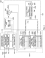
- a signal interference prevention signal generation flow diagram 200 of one embodiment is illustrated. As illustrated, the process starts with the clock 114 providing the fixed time base signal to the PRN sequence generators 110. As illustrated, any number of PRN sequence generators 110-1, 110-2 through 110-N can be used depending on the number of bits used in the frequency index 206.
- Each PRN sequence generator 110 in an embodiment, may be an M-bit linear feedback shift register. Moreover, each linear feedback shift register may have a unique maximum length sequence feedback polynomial.
- An output of the N-bit frequency index 206 is provided to a ramp direction logic block 208 implemented by the controller 208. If the ramp direction is to be in an up ramp direction a 2 N row high frequency table 220 is used.
- the up ramp direction refers to a positive FMCW slope and the down ramp direction refers to a negative FMCW slope.
- the 2 N row high frequency table 220 includes high frequencies 222-1 through 222-2 N -1.
- the 2 N row low frequency table 210 includes low frequencies 212-1 through 212-2 N -1.
- the selected up ramp stop frequency or down ramp stop frequency is provided to a configure FMCW ramp block 230 implemented by the controller 104.
- the configure FMCW ramp block 230 provides that a previous ramp stop frequency 234 is a current ramp start frequency 232. Either the up ramp stop frequency or down ramp stop frequency is used for the stop frequency 234.
- the stop frequency 234 of the FMCW ramp is provided to a unit delay Z -1 240.
- the start frequency 232 of the FMCW ramp is provided to configure the FMCW ramp.
- the FMCW ramp is provided to the frequency synthesizer 116 to generate the output signal of the radar altimeter 100.
- a FMCW ramp dither sequence length of 2 M -1 may be achieved with only 2 N+1 stored frequencies.
- the 2 N+1 frequencies may be stored in two tables: 2N high frequencies and 2N low frequencies.
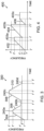
- an initial start frequency f 1 is selected with PRN sequence generator seed values.
- an up ramp 304 in a transmit frame of the radar signal is created until an up ramp stop frequency f 4 is reached at t 1 .
- the up ramp stop frequency f 4 is provided by the high frequency table 220 which is indexed by the PRN sequence generators 110. Varied turnaround times 240a, 240b, 240c 240d are used to allow the total transmit frame time for each frame to be equal.
- the radar signal remains at the stop frequency f 4 until the total transmit frame time is reached at t 2 .
- this transmit frame time (t 2 -t 0 ) is constant for all frames, even as the ramp time varies due to the different ramp start and stop frequencies.
- the times (t 2 -t 0 ), (t 4 -t 2 ), (t 6 -t 4 ) and (t 8 -t 6 ) are all equal. It is therefore necessary that the constant transmit frame time be at least as long as the longest possible ramp time based on the fixed FMCW ramp rate and the values in the high and low frequency tables.
- the stop frequency f 4 of the up ramp 304 is the same as the start frequency f 4 of the down ramp 306 in this example embodiment.
- a down ramp stop frequency f 3 is reached at t 3 and is maintained until t 4 .
- an up ramp 308 of a next transmit frame is started that ends at an up ramp stop frequency f 5 at t 5 .
- a down ramp 310 is started until a down ramp stop frequency f 2 is reached. The process continues this way to creating transmit frames of the radar signal for the radar altimeter 100.
- the up ramps 304 and 308 and the down ramps 306 and 310 may have the same ramp rate (linear slope) to provide a constant range resolution. Hence in theses embodiments only the start and stop frequencies, which are pseudorandomly generated, need to determined.
- the frequency selected from the frequency tables 108 is based on the output index of the PRN sequence generators 110 and will correspond to the "stop" frequency of the current ramp. However, this "stop” frequency is also the "start” frequency of the next ramp, so frequency tables may be referred to as either start frequency tables or stop frequency tables. Frequencies at the lower end of the band will be “start” frequencies for up ramps and “stop” frequencies for down ramps, while frequencies at the upper end of the band will be “stop” frequencies for up ramps and "start” frequencies for down ramps.
- FIG. 3 and the discussion above apply the PRN sequence generators on a triangle FMCW waveform which has both up and down ramp directions.
- This technique may also be applied to sawtooth FMCW (which uses just one ramp direction).
- two separate frequency tables may be used: one table for start frequencies and one for stop frequencies.
- An example of a partial created sawtooth FMCW waveform 400 is illustrated in Figure 4 . Similar to the embodiment illustrated in Figure 3 , this embodiment employs varied turnaround times 403a, 403b and 403d to allow the total transmit frame time for each frame to be equal. To simplify the reception and processing of the radar signal, this transmit frame time (t 2 -t 0 ) is constant for all frames, even as the ramp time varies due to the different ramp start and stop frequencies.
- a PRN seed value may be used to index a start frequency f 2 of ramp 402 at t 0 .
- a stop frequency f 5 is provided by a stop frequency table which is indexed from the PRN sequence generators. The stop frequency f 5 is reached at t 1 .
- the next up ramp 404 starts at frequency f 3 which is provided from a start frequency table. In the example, embodiment of the Figure 4 , the next ramp up 404 starts at t 2 after the turnaround time 403a. Up ramp 404 stops at frequency f 6 at t 3 .
- the next up ramp 406 starts at frequency f 1 provided by the start ramp table. This process continues creating the transmit frames of a signal for the radar altimeter 100.
- a same index frequency value generated by the PRN sequence generators may be used that corresponds to different frequencies for the stop and start of the up ramps.
- the ramp rate of ramps 402, 404 and 406 in this embodiment may also be fixed to provide a constant radar range resolution.
Landscapes
- Engineering & Computer Science (AREA)
- Radar, Positioning & Navigation (AREA)
- Remote Sensing (AREA)
- Computer Networks & Wireless Communication (AREA)
- Physics & Mathematics (AREA)
- General Physics & Mathematics (AREA)
- Electromagnetism (AREA)
- Signal Processing (AREA)
- Radar Systems Or Details Thereof (AREA)
Claims (9)
- Radarhöhenmesser-Signalinterferenzpräventionssystem (102) für einen Radarhöhenmesser (100) mit frequenzmodulierter kontinuierlicher Welle, FMCW, das Signalinterferenzpräventionssystem (102) umfassend:einen Frequenzsynthesizer (112), um FMCW-Rampen in einem Radiofrequenz-, RF-, Signal zu erzeugen, das in dem FMCW-Radarhöhenmesser (100) verwendet wird, wobei eine Rampenrate des Frequenzsynthesizers (112) festgelegt ist, um eine konstante Radarbereichsauflösung bereitzustellen, wobei eine Übertragungsframezeit des Frequenzsynthesizers (112) festgelegt ist, um eine vereinfachte Signalverarbeitung in dem FMCW-Radarhöhenmesser (100) bereitzustellen;mindestens einen Speicher (106), wobei mindestens eine 2 N -zeilige Hochfrequenztabelle (220) und eine 2 N -zeilige Niederfrequenztabelle (210) in dem mindestens einen Speicher (106) gespeichert sind; undein feldprogrammierbares Gate-Array, FPGA, (104), das dazu konfiguriert ist N Pseudozufalls-Rauschsequenzerzeuger (110) zu implementieren, um einen N-bit ganzzahligen Wert zu erzeugen, der beim Auswählen einer Startfrequenz der FMCW-Rampe für ein aktuelles Frame des Radiofrequenz-, RF-, Signals als ein Index in einer der 2 N -zeiligen Hochfrequenztabelle (220) und der 2 N -zeiligen Niederfrequenztabelle (210) verwendet wird, wobei das FPGA (104) ferner dazu konfiguriert ist, eine Startfrequenz einer FMCW-Rampe in einem nächsten Übertragungsframe als eine Stoppfrequenz der FMCW-Rampe in dem aktuellen Frame zu verwenden, wobei die N Pseudozufalls-Rauschsequenzerzeuger (110) dem Frequenzsynthesizer um ein Frame voraus getaktet sind, sodass die Start- und Stoppfrequenz an Beginn jedes Frames konfiguriert sein kann, wobei die 2 N -zeilige Hochfrequenztabelle (220) verwendet wird, wenn eine Rampenrichtung eine nach oben gerichtete Rampenrichtung ist und die 2 N-zeilige Niederfrequenztabelle (210) verwendet wird, wenn die Rampenrichtung eine nach unten gerichtete Rampenrichtung ist.
- Signalinterferenzpräventionssystem (102) nach Anspruch 1, wobei die N Pseudozufalls-Rauschsequenzerzeuger (110) ferner Folgendes umfassen:
drei Pseudozufalls-Rauschsequenzerzeuger (110-1 bis 110-3), wobei jeder Pseudozufalls-Rauschsequenzerzeuger (110-1 bis 110-3) sein eigenes Rückkopplungspolynom und seinen eigenen Ausgangswert aufweist, wobei jeder Pseudozufalls-Rauschsequenzerzeuger (110-1 bis 110-3) dazu konfiguriert ist, eine maximale Längensequenz auszugeben, wobei das FPGA (104) dazu konfiguriert ist, die Ausgaben der drei Pseudozufalls-Rauschsequenzerzeuger (110-1 bis 110-3) zu kombinieren, um den N-bit ganzzahligen Wert zu bestimmen, der als der Index in der mindestens einen von der 2 N -zeiligen Hochfrequenztabelle (220) und der 2 N -zeiligen Niederfrequenztabelle (210) verwendet wird. - Signalinterferenzpräventionssystem (102) nach Anspruch 1, wobei die Dauer der FMCW-Rampen durch die von den N Pseudozufalls-Rauschsequenzerzeugern (110) darin ausgewählten Start- und Stoppfrequenzen moduliert wird, wodurch ein Dithering des effektiven Pulswiederholungsintervalls, PRI, des FMCW-Radarhöhenmessers (100) ohne eine Veränderung der Übertragungsframezeit des FMCW-Radarhöhenmessers (100) verursacht wird.
- Signalinterferenzpräventionssystem (102) nach Anspruch 1, ferner umfassend:
einen Taktgeber (114) in Kommunikation mit den N Pseudozufalls-Rauschsequenzerzeugern (110), um ein festgelegtes Zeitbasissignal für die N Pseudozufalls-Rauschsequenzerzeuger (110) bereitzustellen. - Signalinterferenzpräventionssystem nach Anspruch 1, wobei der mindestens eine Speicher (106), welcher die mindestens eine von der 2 N -zeiligen Hochfrequenztabelle (220) und der 2 N -zeiligen Niederfrequenztabelle (210) speichert, Register des FPGA (104) beinhaltet.
- Verfahren zum Betreiben eines Radarhöhenmesser-Signalinterferenzpräventionssystems nach Anspruch 1, das Verfahren umfassend:Erzeugen von N-bit ganzzahligen Werten mit N Pseudozufalls-Rauschsequenzerzeugern (110);Verwenden der erzeugten N-bit ganzzahligen Werte als Indizes, um mindestens eine von Startfrequenzen und Stoppfrequenzen aus einer von einer 2 N -zeiligen Hochfrequenztabelle (220) und einer 2 N -zeiligen Niederfrequenztabelle (210) für Rampen mit frequenzmodulierter kontinuierlicher Welle, FMCW, für ein erzeugtes Radarsignals auszuwählen;Bestimmen einer Rampenrichtung für ein aktuelles Übertragungsframe;Verwenden einer nach unten gerichteten Rampenstoppfrequenz aus der 2 N-zeiligen Niederfrequenztabelle (210), wenn die Richtung der Rampe in dem aktuellen Übertragungsframe nach unten gerichtet ist;Verwenden einer nach oben gerichteten Rampenstoppfrequenz aus der 2 N-zeiligen Hochfrequenztabelle (220), wenn die Richtung der Rampe in dem aktuellen Übertragungsframe nach oben gerichtet ist;Bereitstellen der ausgewählten mindestens einen von den Startfrequenzen und den Stoppfrequenzen an einen Frequenzsynthesizer (112); undVerwenden der mindestens einen von den Startfrequenzen und den Stoppfrequenzen bei dem Erzeugen von Übertragungsframes des Radarsignals mit dem Frequenzsynthesizer (112).
- Verfahren nach Anspruch 6, ferner umfassend:
Takten des N Pseudozufalls-Rauschsequenzerzeugers um ein Frame im Voraus zu dem Frequenzsynthesizer (112), sodass eine Start- und Stoppfrequenz an Beginn jedes Übertragungsframes konfiguriert werden kann. - Verfahren nach Anspruch 6, ferner umfassend:
Verwenden einer Stoppfrequenz eines aktuellen Übertragungsframes als eine Startfrequenz eines nächsten Übertragungsframes. - Verfahren nach Anspruch 8, ferner umfassend:
Beibehalten der Frequenz des erzeugten Radarsignals an der Stoppfrequenz des aktuellen Übertragungsframes nach Abschluss einer Frequenzrampe für einen Rest einer festgelegten Übertragungsframezeit.
Applications Claiming Priority (1)
| Application Number | Priority Date | Filing Date | Title |
|---|---|---|---|
| US15/451,336 US10495728B2 (en) | 2017-03-06 | 2017-03-06 | Signal interference prevention system for a frequency-modulated continuous wave radar altimeter |
Publications (2)
| Publication Number | Publication Date |
|---|---|
| EP3373028A1 EP3373028A1 (de) | 2018-09-12 |
| EP3373028B1 true EP3373028B1 (de) | 2024-08-28 |
Family
ID=61569130
Family Applications (1)
| Application Number | Title | Priority Date | Filing Date |
|---|---|---|---|
| EP18160054.5A Active EP3373028B1 (de) | 2017-03-06 | 2018-03-05 | Signalinterferenzvermeidungssystem für einen frequenzmodulierten dauerstrichradar-höhenmesser |
Country Status (3)
| Country | Link |
|---|---|
| US (1) | US10495728B2 (de) |
| EP (1) | EP3373028B1 (de) |
| CN (1) | CN108535703B (de) |
Families Citing this family (22)
| Publication number | Priority date | Publication date | Assignee | Title |
|---|---|---|---|---|
| US11002829B2 (en) * | 2016-04-15 | 2021-05-11 | Mediatek Inc. | Radar interference mitigation method and apparatus |
| EP3410150B1 (de) * | 2017-05-30 | 2022-01-19 | Nxp B.V. | Vorrichtung zur detektion und entfernungsmessung |
| CN107682011B (zh) * | 2017-09-26 | 2024-02-23 | 天津光电通信技术有限公司 | 一种信噪比可调的中频信号发生器的实现方法 |
| US10605892B2 (en) * | 2017-11-08 | 2020-03-31 | GM Global Technology Operations LLC | System and method for pseudo randomized chirp scheduling for interference avoidance |
| US11073599B2 (en) * | 2018-05-07 | 2021-07-27 | Qualcomm Incorporated | Radar interference mitigation using a pseudorandom offset |
| FR3084751B1 (fr) * | 2018-08-02 | 2020-06-26 | Thales | Procede de traitement distance haute resolution |
| US10942909B2 (en) * | 2018-09-25 | 2021-03-09 | Salesforce.Com, Inc. | Efficient production and consumption for data changes in a database under high concurrency |
| EP3882653B1 (de) | 2018-11-21 | 2023-07-12 | SZ DJI Technology Co., Ltd. | Mikrowellenradar und unbemanntes luftfahrzeug |
| CN115932737A (zh) * | 2019-02-01 | 2023-04-07 | 华为技术有限公司 | 一种目标物探测方法及对应的探测装置 |
| US11740345B2 (en) | 2019-03-06 | 2023-08-29 | Texas Instruments Incorporated | Dithering FMCW radar parameters to mitigate spurious signals |
| US10855328B1 (en) * | 2019-07-03 | 2020-12-01 | Qualcomm Incorporated | Interference suppression for multi-radar coexistence |
| CN113156405B (zh) * | 2020-01-22 | 2022-12-20 | 苏州一径科技有限公司 | Fmcw激光雷达多源串扰解耦方法、fmcw激光雷达及雷达系统 |
| CN113325374A (zh) * | 2020-02-28 | 2021-08-31 | 加特兰微电子科技(上海)有限公司 | 抗干扰方法、装置、雷达系统及存储介质 |
| DE112021001114T5 (de) * | 2020-04-17 | 2022-12-29 | Murata Manufacturing Co., Ltd. | Radarvorrichtung, fahrzeug und verfahren zum schätzen einer anzahl von ankommenden wellen |
| US11621767B2 (en) | 2020-08-18 | 2023-04-04 | Arinc Incorporated | Coordination of wireless avionics intra-communications (WAIC) with radio altimeter signals |
| US11899095B2 (en) * | 2020-09-17 | 2024-02-13 | Texas Instruments Incorporated | Doppler processing in frequency-modulated continuous wave radar systems using dither |
| US11994575B2 (en) * | 2020-10-16 | 2024-05-28 | Texas Instruments Incorporated | Frequency modulated continuous wave radar system with interference mitigation |
| CN113156383B (zh) * | 2021-04-21 | 2024-02-20 | 杭州加速科技有限公司 | 基于fpga的雷达信号抗干扰方法、系统及数据处理设备 |
| US12468011B2 (en) | 2022-06-07 | 2025-11-11 | Honeywell International Inc. | Systems and methods for mitigating telecommunications signal interference to radar altimeters |
| CN115166642B (zh) * | 2022-06-24 | 2024-09-03 | 中国电子科技集团公司第二十九研究所 | 一种pri为伪随机抖动序列的雷达信号分选方法 |
| CN119828104A (zh) * | 2023-10-12 | 2025-04-15 | 深圳市速腾聚创科技有限公司 | 雷达控制方法、装置、终端设备及存储介质 |
| CN118884454A (zh) * | 2024-07-30 | 2024-11-01 | 哈尔滨工程大学 | 基于伪随机序列的分时隙激光tof阵列测距成像系统 |
Citations (1)
| Publication number | Priority date | Publication date | Assignee | Title |
|---|---|---|---|---|
| EP2863239A1 (de) * | 2013-09-26 | 2015-04-22 | Honeywell International Inc. | FMCW-Radar mit verfeinerter Messung mit festen Frequenzen |
Family Cites Families (16)
| Publication number | Priority date | Publication date | Assignee | Title |
|---|---|---|---|---|
| US5347283A (en) | 1989-06-14 | 1994-09-13 | Hughes Aircraft Company | Frequency agile radar |
| US5361070B1 (en) * | 1993-04-12 | 2000-05-16 | Univ California | Ultra-wideband radar motion sensor |
| US6577269B2 (en) * | 2000-08-16 | 2003-06-10 | Raytheon Company | Radar detection method and apparatus |
| EP1870730A3 (de) * | 2000-08-16 | 2011-07-20 | Valeo Radar Systems, Inc. | Radarsysteme und -verfahren für Kraftfahrzeuge |
| US20040130482A1 (en) * | 2003-01-02 | 2004-07-08 | Yu-Shan Lin | Digital controlled linear sweep frequency mode for FMCW radar altimeter |
| DE602007005937D1 (de) * | 2007-06-11 | 2010-05-27 | Mitsubishi Electric Corp | Objekterkennung |
| US7518547B2 (en) * | 2007-07-16 | 2009-04-14 | Honeywell International Inc. | Method and system of interference detection for radar altimeters |
| GB2472623A (en) | 2009-08-12 | 2011-02-16 | Thales Holdings Uk Plc | Continuous wave radar with frequency shift keying |
| EP2390679B1 (de) * | 2010-05-27 | 2012-10-03 | Mitsubishi Electric R&D Centre Europe B.V. | Automobilradar mit Funkfrequenzstörungsvermeidung |
| US8866667B2 (en) * | 2012-02-22 | 2014-10-21 | Honeywell International Inc. | High sensitivity single antenna FMCW radar |
| US9081094B2 (en) * | 2012-02-22 | 2015-07-14 | Honeywell International Inc. | Aircraft radar altimeter structure |
| FR2989782B1 (fr) | 2012-04-20 | 2014-05-23 | Thales Sa | Systeme de radio adapte pour fonctionner dans une installation de radio altimetie multiple |
| US9945933B2 (en) * | 2015-07-24 | 2018-04-17 | Autoliv Asp, Inc. | Apparatus and method for mitigating interference in a frequency-modulated continuous-wave (FMCW) automotive radar system |
| US10502824B2 (en) * | 2015-11-09 | 2019-12-10 | Infineon Technologies Ag | Frequency modulation scheme for FMCW radar |
| US11002829B2 (en) | 2016-04-15 | 2021-05-11 | Mediatek Inc. | Radar interference mitigation method and apparatus |
| EP4628936A3 (de) * | 2016-04-25 | 2026-03-11 | Robert Bosch GmbH | Verringerung der pmcw-pmcw-interferenz |
-
2017
- 2017-03-06 US US15/451,336 patent/US10495728B2/en active Active
-
2018
- 2018-03-05 EP EP18160054.5A patent/EP3373028B1/de active Active
- 2018-03-05 CN CN201810179046.2A patent/CN108535703B/zh active Active
Patent Citations (1)
| Publication number | Priority date | Publication date | Assignee | Title |
|---|---|---|---|---|
| EP2863239A1 (de) * | 2013-09-26 | 2015-04-22 | Honeywell International Inc. | FMCW-Radar mit verfeinerter Messung mit festen Frequenzen |
Also Published As
| Publication number | Publication date |
|---|---|
| US10495728B2 (en) | 2019-12-03 |
| CN108535703B (zh) | 2024-01-12 |
| EP3373028A1 (de) | 2018-09-12 |
| US20180252797A1 (en) | 2018-09-06 |
| CN108535703A (zh) | 2018-09-14 |
Similar Documents
| Publication | Publication Date | Title |
|---|---|---|
| EP3373028B1 (de) | Signalinterferenzvermeidungssystem für einen frequenzmodulierten dauerstrichradar-höhenmesser | |
| US10359504B2 (en) | Apparatus and method for mitigating interference in an automotive radar system | |
| EP1777546B1 (de) | Objekterkennung | |
| EP2821808B1 (de) | Radarvorrichtung und signalverarbeitungsverfahren | |
| EP2006709B1 (de) | Objekterkennung | |
| US9075138B2 (en) | Efficient pulse Doppler radar with no blind ranges, range ambiguities, blind speeds, or Doppler ambiguities | |
| KR101135982B1 (ko) | 주파수 변조 연속파 레이다에서 간섭 제거를 위한 시스템 간 동기화 방법 | |
| EP2391022B1 (de) | Klassifizierung von Störungen | |
| EP2390679A1 (de) | Automobilradar mit Funkfrequenzstörungsvermeidung | |
| US20130106646A1 (en) | Radar apparatus with different operation modes | |
| EP2284565A1 (de) | Dauerstrichradar | |
| JP2017207368A (ja) | 速度検出装置 | |
| US12436258B2 (en) | Radar measuring device and method with dual radar signal generation | |
| JP6467974B2 (ja) | 信号発生装置と方法とレーダ装置とプログラム | |
| US20180306911A1 (en) | Method and system for resolving range ambiguity | |
| US20210190903A1 (en) | Radar apparatus and signal processing method | |
| EP3208633A1 (de) | Verfahren und system zur verbesserung der höhemessung mit einem fmcw-radar-höhenmessersystem | |
| EP3717931B1 (de) | Radarsystembetriebsverfahren und radarsystem mit verbesserter entfernungsauflösung durch gegenseitig verzögerte orthogonale codes | |
| CN118233268A (zh) | 用于车辆中的干扰减轻的时频传感器编码的方法和系统 | |
| JP2012103196A (ja) | レーダ装置 | |
| JP5633848B2 (ja) | 超広帯域パルス・センサ及びその干渉回避方法 | |
| GB2563444A (en) | Radar with stepped frequency complementary code sequences | |
| RU2533198C1 (ru) | Способ управления величиной разрешающей способности радиолокационной станции | |
| JP6759153B2 (ja) | レーダ装置及びそのレーダ信号処理方法 | |
| RU2392704C1 (ru) | Способ повышения широкополосности приемопередающего модуля фазированной антенной решетки, использующего генерацию сигналов методом прямого цифрового синтеза, и варианты его реализации |
Legal Events
| Date | Code | Title | Description |
|---|---|---|---|
| PUAI | Public reference made under article 153(3) epc to a published international application that has entered the european phase |
Free format text: ORIGINAL CODE: 0009012 |
|
| STAA | Information on the status of an ep patent application or granted ep patent |
Free format text: STATUS: REQUEST FOR EXAMINATION WAS MADE |
|
| 17P | Request for examination filed |
Effective date: 20180305 |
|
| AK | Designated contracting states |
Kind code of ref document: A1 Designated state(s): AL AT BE BG CH CY CZ DE DK EE ES FI FR GB GR HR HU IE IS IT LI LT LU LV MC MK MT NL NO PL PT RO RS SE SI SK SM TR |
|
| AX | Request for extension of the european patent |
Extension state: BA ME |
|
| STAA | Information on the status of an ep patent application or granted ep patent |
Free format text: STATUS: EXAMINATION IS IN PROGRESS |
|
| 17Q | First examination report despatched |
Effective date: 20200513 |
|
| P01 | Opt-out of the competence of the unified patent court (upc) registered |
Effective date: 20230421 |
|
| GRAP | Despatch of communication of intention to grant a patent |
Free format text: ORIGINAL CODE: EPIDOSNIGR1 |
|
| STAA | Information on the status of an ep patent application or granted ep patent |
Free format text: STATUS: GRANT OF PATENT IS INTENDED |
|
| INTG | Intention to grant announced |
Effective date: 20240417 |
|
| GRAS | Grant fee paid |
Free format text: ORIGINAL CODE: EPIDOSNIGR3 |
|
| GRAA | (expected) grant |
Free format text: ORIGINAL CODE: 0009210 |
|
| STAA | Information on the status of an ep patent application or granted ep patent |
Free format text: STATUS: THE PATENT HAS BEEN GRANTED |
|
| AK | Designated contracting states |
Kind code of ref document: B1 Designated state(s): AL AT BE BG CH CY CZ DE DK EE ES FI FR GB GR HR HU IE IS IT LI LT LU LV MC MK MT NL NO PL PT RO RS SE SI SK SM TR |
|
| REG | Reference to a national code |
Ref country code: GB Ref legal event code: FG4D |
|
| REG | Reference to a national code |
Ref country code: CH Ref legal event code: EP |
|
| REG | Reference to a national code |
Ref country code: DE Ref legal event code: R096 Ref document number: 602018073548 Country of ref document: DE |
|
| REG | Reference to a national code |
Ref country code: IE Ref legal event code: FG4D |
|
| REG | Reference to a national code |
Ref country code: NL Ref legal event code: FP |
|
| REG | Reference to a national code |
Ref country code: LT Ref legal event code: MG9D |
|
| PG25 | Lapsed in a contracting state [announced via postgrant information from national office to epo] |
Ref country code: NO Free format text: LAPSE BECAUSE OF FAILURE TO SUBMIT A TRANSLATION OF THE DESCRIPTION OR TO PAY THE FEE WITHIN THE PRESCRIBED TIME-LIMIT Effective date: 20241128 |
|
| REG | Reference to a national code |
Ref country code: AT Ref legal event code: MK05 Ref document number: 1718543 Country of ref document: AT Kind code of ref document: T Effective date: 20240828 |
|
| PG25 | Lapsed in a contracting state [announced via postgrant information from national office to epo] |
Ref country code: PL Free format text: LAPSE BECAUSE OF FAILURE TO SUBMIT A TRANSLATION OF THE DESCRIPTION OR TO PAY THE FEE WITHIN THE PRESCRIBED TIME-LIMIT Effective date: 20240828 Ref country code: FI Free format text: LAPSE BECAUSE OF FAILURE TO SUBMIT A TRANSLATION OF THE DESCRIPTION OR TO PAY THE FEE WITHIN THE PRESCRIBED TIME-LIMIT Effective date: 20240828 Ref country code: PT Free format text: LAPSE BECAUSE OF FAILURE TO SUBMIT A TRANSLATION OF THE DESCRIPTION OR TO PAY THE FEE WITHIN THE PRESCRIBED TIME-LIMIT Effective date: 20241230 Ref country code: GR Free format text: LAPSE BECAUSE OF FAILURE TO SUBMIT A TRANSLATION OF THE DESCRIPTION OR TO PAY THE FEE WITHIN THE PRESCRIBED TIME-LIMIT Effective date: 20241129 |
|
| PG25 | Lapsed in a contracting state [announced via postgrant information from national office to epo] |
Ref country code: BG Free format text: LAPSE BECAUSE OF FAILURE TO SUBMIT A TRANSLATION OF THE DESCRIPTION OR TO PAY THE FEE WITHIN THE PRESCRIBED TIME-LIMIT Effective date: 20240828 |
|
| PG25 | Lapsed in a contracting state [announced via postgrant information from national office to epo] |
Ref country code: LV Free format text: LAPSE BECAUSE OF FAILURE TO SUBMIT A TRANSLATION OF THE DESCRIPTION OR TO PAY THE FEE WITHIN THE PRESCRIBED TIME-LIMIT Effective date: 20240828 |
|
| PG25 | Lapsed in a contracting state [announced via postgrant information from national office to epo] |
Ref country code: IS Free format text: LAPSE BECAUSE OF FAILURE TO SUBMIT A TRANSLATION OF THE DESCRIPTION OR TO PAY THE FEE WITHIN THE PRESCRIBED TIME-LIMIT Effective date: 20241228 Ref country code: AT Free format text: LAPSE BECAUSE OF FAILURE TO SUBMIT A TRANSLATION OF THE DESCRIPTION OR TO PAY THE FEE WITHIN THE PRESCRIBED TIME-LIMIT Effective date: 20240828 |
|
| PG25 | Lapsed in a contracting state [announced via postgrant information from national office to epo] |
Ref country code: HR Free format text: LAPSE BECAUSE OF FAILURE TO SUBMIT A TRANSLATION OF THE DESCRIPTION OR TO PAY THE FEE WITHIN THE PRESCRIBED TIME-LIMIT Effective date: 20240828 |
|
| PG25 | Lapsed in a contracting state [announced via postgrant information from national office to epo] |
Ref country code: RS Free format text: LAPSE BECAUSE OF FAILURE TO SUBMIT A TRANSLATION OF THE DESCRIPTION OR TO PAY THE FEE WITHIN THE PRESCRIBED TIME-LIMIT Effective date: 20241128 Ref country code: ES Free format text: LAPSE BECAUSE OF FAILURE TO SUBMIT A TRANSLATION OF THE DESCRIPTION OR TO PAY THE FEE WITHIN THE PRESCRIBED TIME-LIMIT Effective date: 20240828 |
|
| PG25 | Lapsed in a contracting state [announced via postgrant information from national office to epo] |
Ref country code: RS Free format text: LAPSE BECAUSE OF FAILURE TO SUBMIT A TRANSLATION OF THE DESCRIPTION OR TO PAY THE FEE WITHIN THE PRESCRIBED TIME-LIMIT Effective date: 20241128 Ref country code: PT Free format text: LAPSE BECAUSE OF FAILURE TO SUBMIT A TRANSLATION OF THE DESCRIPTION OR TO PAY THE FEE WITHIN THE PRESCRIBED TIME-LIMIT Effective date: 20241230 Ref country code: PL Free format text: LAPSE BECAUSE OF FAILURE TO SUBMIT A TRANSLATION OF THE DESCRIPTION OR TO PAY THE FEE WITHIN THE PRESCRIBED TIME-LIMIT Effective date: 20240828 Ref country code: NO Free format text: LAPSE BECAUSE OF FAILURE TO SUBMIT A TRANSLATION OF THE DESCRIPTION OR TO PAY THE FEE WITHIN THE PRESCRIBED TIME-LIMIT Effective date: 20241128 Ref country code: LV Free format text: LAPSE BECAUSE OF FAILURE TO SUBMIT A TRANSLATION OF THE DESCRIPTION OR TO PAY THE FEE WITHIN THE PRESCRIBED TIME-LIMIT Effective date: 20240828 Ref country code: IS Free format text: LAPSE BECAUSE OF FAILURE TO SUBMIT A TRANSLATION OF THE DESCRIPTION OR TO PAY THE FEE WITHIN THE PRESCRIBED TIME-LIMIT Effective date: 20241228 Ref country code: HR Free format text: LAPSE BECAUSE OF FAILURE TO SUBMIT A TRANSLATION OF THE DESCRIPTION OR TO PAY THE FEE WITHIN THE PRESCRIBED TIME-LIMIT Effective date: 20240828 Ref country code: GR Free format text: LAPSE BECAUSE OF FAILURE TO SUBMIT A TRANSLATION OF THE DESCRIPTION OR TO PAY THE FEE WITHIN THE PRESCRIBED TIME-LIMIT Effective date: 20241129 Ref country code: FI Free format text: LAPSE BECAUSE OF FAILURE TO SUBMIT A TRANSLATION OF THE DESCRIPTION OR TO PAY THE FEE WITHIN THE PRESCRIBED TIME-LIMIT Effective date: 20240828 Ref country code: ES Free format text: LAPSE BECAUSE OF FAILURE TO SUBMIT A TRANSLATION OF THE DESCRIPTION OR TO PAY THE FEE WITHIN THE PRESCRIBED TIME-LIMIT Effective date: 20240828 Ref country code: BG Free format text: LAPSE BECAUSE OF FAILURE TO SUBMIT A TRANSLATION OF THE DESCRIPTION OR TO PAY THE FEE WITHIN THE PRESCRIBED TIME-LIMIT Effective date: 20240828 Ref country code: AT Free format text: LAPSE BECAUSE OF FAILURE TO SUBMIT A TRANSLATION OF THE DESCRIPTION OR TO PAY THE FEE WITHIN THE PRESCRIBED TIME-LIMIT Effective date: 20240828 |
|
| PG25 | Lapsed in a contracting state [announced via postgrant information from national office to epo] |
Ref country code: SM Free format text: LAPSE BECAUSE OF FAILURE TO SUBMIT A TRANSLATION OF THE DESCRIPTION OR TO PAY THE FEE WITHIN THE PRESCRIBED TIME-LIMIT Effective date: 20240828 Ref country code: DK Free format text: LAPSE BECAUSE OF FAILURE TO SUBMIT A TRANSLATION OF THE DESCRIPTION OR TO PAY THE FEE WITHIN THE PRESCRIBED TIME-LIMIT Effective date: 20240828 Ref country code: RO Free format text: LAPSE BECAUSE OF FAILURE TO SUBMIT A TRANSLATION OF THE DESCRIPTION OR TO PAY THE FEE WITHIN THE PRESCRIBED TIME-LIMIT Effective date: 20240828 |
|
| PG25 | Lapsed in a contracting state [announced via postgrant information from national office to epo] |
Ref country code: EE Free format text: LAPSE BECAUSE OF FAILURE TO SUBMIT A TRANSLATION OF THE DESCRIPTION OR TO PAY THE FEE WITHIN THE PRESCRIBED TIME-LIMIT Effective date: 20240828 |
|
| PG25 | Lapsed in a contracting state [announced via postgrant information from national office to epo] |
Ref country code: CZ Free format text: LAPSE BECAUSE OF FAILURE TO SUBMIT A TRANSLATION OF THE DESCRIPTION OR TO PAY THE FEE WITHIN THE PRESCRIBED TIME-LIMIT Effective date: 20240828 |
|
| PG25 | Lapsed in a contracting state [announced via postgrant information from national office to epo] |
Ref country code: SK Free format text: LAPSE BECAUSE OF FAILURE TO SUBMIT A TRANSLATION OF THE DESCRIPTION OR TO PAY THE FEE WITHIN THE PRESCRIBED TIME-LIMIT Effective date: 20240828 Ref country code: IT Free format text: LAPSE BECAUSE OF FAILURE TO SUBMIT A TRANSLATION OF THE DESCRIPTION OR TO PAY THE FEE WITHIN THE PRESCRIBED TIME-LIMIT Effective date: 20240828 |
|
| REG | Reference to a national code |
Ref country code: DE Ref legal event code: R097 Ref document number: 602018073548 Country of ref document: DE |
|
| PLBE | No opposition filed within time limit |
Free format text: ORIGINAL CODE: 0009261 |
|
| STAA | Information on the status of an ep patent application or granted ep patent |
Free format text: STATUS: NO OPPOSITION FILED WITHIN TIME LIMIT |
|
| 26N | No opposition filed |
Effective date: 20250530 |
|
| PG25 | Lapsed in a contracting state [announced via postgrant information from national office to epo] |
Ref country code: SE Free format text: LAPSE BECAUSE OF FAILURE TO SUBMIT A TRANSLATION OF THE DESCRIPTION OR TO PAY THE FEE WITHIN THE PRESCRIBED TIME-LIMIT Effective date: 20240828 |
|
| PG25 | Lapsed in a contracting state [announced via postgrant information from national office to epo] |
Ref country code: MC Free format text: LAPSE BECAUSE OF FAILURE TO SUBMIT A TRANSLATION OF THE DESCRIPTION OR TO PAY THE FEE WITHIN THE PRESCRIBED TIME-LIMIT Effective date: 20240828 |
|
| REG | Reference to a national code |
Ref country code: CH Ref legal event code: H13 Free format text: ST27 STATUS EVENT CODE: U-0-0-H10-H13 (AS PROVIDED BY THE NATIONAL OFFICE) Effective date: 20251023 |
|
| PG25 | Lapsed in a contracting state [announced via postgrant information from national office to epo] |
Ref country code: LU Free format text: LAPSE BECAUSE OF NON-PAYMENT OF DUE FEES Effective date: 20250305 |
|
| REG | Reference to a national code |
Ref country code: BE Ref legal event code: MM Effective date: 20250331 |
|
| PG25 | Lapsed in a contracting state [announced via postgrant information from national office to epo] |
Ref country code: BE Free format text: LAPSE BECAUSE OF NON-PAYMENT OF DUE FEES Effective date: 20250331 |
|
| PG25 | Lapsed in a contracting state [announced via postgrant information from national office to epo] |
Ref country code: CH Free format text: LAPSE BECAUSE OF NON-PAYMENT OF DUE FEES Effective date: 20250331 |
|
| PG25 | Lapsed in a contracting state [announced via postgrant information from national office to epo] |
Ref country code: IE Free format text: LAPSE BECAUSE OF NON-PAYMENT OF DUE FEES Effective date: 20250305 |
|
| PGFP | Annual fee paid to national office [announced via postgrant information from national office to epo] |
Ref country code: GB Payment date: 20260319 Year of fee payment: 9 |
|
| PGFP | Annual fee paid to national office [announced via postgrant information from national office to epo] |
Ref country code: DE Payment date: 20260320 Year of fee payment: 9 |
|
| PGFP | Annual fee paid to national office [announced via postgrant information from national office to epo] |
Ref country code: NL Payment date: 20260323 Year of fee payment: 9 |
|
| PGFP | Annual fee paid to national office [announced via postgrant information from national office to epo] |
Ref country code: FR Payment date: 20260323 Year of fee payment: 9 |
|
| PGFP | Annual fee paid to national office [announced via postgrant information from national office to epo] |
Ref country code: TR Payment date: 20260223 Year of fee payment: 9 |