EP3373779B1 - Leichtes anschliessen eines flüssigtanks an einem getränkeautomaten - Google Patents
Leichtes anschliessen eines flüssigtanks an einem getränkeautomaten Download PDFInfo
- Publication number
- EP3373779B1 EP3373779B1 EP16791629.5A EP16791629A EP3373779B1 EP 3373779 B1 EP3373779 B1 EP 3373779B1 EP 16791629 A EP16791629 A EP 16791629A EP 3373779 B1 EP3373779 B1 EP 3373779B1
- Authority
- EP
- European Patent Office
- Prior art keywords
- tank
- module
- liquid
- lid
- outlet
- Prior art date
- Legal status (The legal status is an assumption and is not a legal conclusion. Google has not performed a legal analysis and makes no representation as to the accuracy of the status listed.)
- Active
Links
Images

Classifications
-
- A—HUMAN NECESSITIES
- A47—FURNITURE; DOMESTIC ARTICLES OR APPLIANCES; COFFEE MILLS; SPICE MILLS; SUCTION CLEANERS IN GENERAL
- A47J—KITCHEN EQUIPMENT; COFFEE MILLS; SPICE MILLS; APPARATUS FOR MAKING BEVERAGES
- A47J31/00—Apparatus for making beverages
- A47J31/44—Parts or details or accessories of beverage-making apparatus
- A47J31/4403—Constructional details
-
- A—HUMAN NECESSITIES
- A47—FURNITURE; DOMESTIC ARTICLES OR APPLIANCES; COFFEE MILLS; SPICE MILLS; SUCTION CLEANERS IN GENERAL
- A47J—KITCHEN EQUIPMENT; COFFEE MILLS; SPICE MILLS; APPARATUS FOR MAKING BEVERAGES
- A47J31/00—Apparatus for making beverages
- A47J31/24—Coffee-making apparatus in which hot water is passed through the filter under pressure, i.e. in which the coffee grounds are extracted under pressure
- A47J31/34—Coffee-making apparatus in which hot water is passed through the filter under pressure, i.e. in which the coffee grounds are extracted under pressure with hot water under liquid pressure
- A47J31/36—Coffee-making apparatus in which hot water is passed through the filter under pressure, i.e. in which the coffee grounds are extracted under pressure with hot water under liquid pressure with mechanical pressure-producing means
Definitions
- the present invention concerns a beverage machine having a beverage preparation module and a liquid storage tank that is disconnectably connectable thereto.
- a "beverage” is meant to include any human-consumable liquid substance, such as tea, coffee, hot or cold chocolate, milk, soup, baby food, etc...
- a “capsule” is meant to include any pre-portioned beverage ingredient, such as a flavouring ingredient, within an enclosing packaging of any material, in particular an airtight packaging, e.g. plastic, aluminium, recyclable and/or biodegradable packagings, and of any shape and structure, including soft pods or rigid cartridges containing the ingredient.
- the capsule may contain an amount of ingredient for preparing a single beverage portion or a plurality of beverage portions.
- beverage machines use capsules containing ingredients to be extracted or to be dissolved and/or ingredients that are stored and dosed automatically in the machine or else are added at the time of preparation of the drink.
- Other beverage machines use loose ingredients to prepare beverages.
- Some beverage machines possess filling means that include a pump for liquid, usually water, which pumps the liquid from a source of water that is cold or indeed heated through heating means, e.g. a thermoblock or the like.
- a capsule containing beverage ingredients is inserted in a brewing device.
- the brewing device is tightly closed about the capsule, water is injected at the first face of the capsule, the beverage is produced in the closed volume of the capsule and a brewed beverage can be drained from a second face of the capsule and collected into a receptacle such as a cup or glass.
- Brewing devices have been developed to facilitate insertion of a "fresh" capsule and removal of the capsule upon use.
- the brewing devices comprise two parts relatively movable from a configuration for inserting/removing a capsule to a configuration for brewing the ingredient in the capsule.
- a beverage machine typically includes a housing containing a beverage processing module and a water tank in fluid communication with the beverage processing module.
- beverage machines are disclosed in EP 1 208 782 , EP 1 267 687 , EP 1 686 879 , EP 1 731 065 , EP 1 829 469 , EP 1 864 598 , EP 1 865 815 , EP 1 867 260 , EP 1 878 368 , EP 2 222 210 , EP 2 222 211 , EP 2 222 212 , EP 2 227 121 , EP 2 227 122 , US 2008/0006159 , US 7,165,488 , WO 2007/111884 , WO 2009/074553 , WO 2010/015427 and WO 2012/055767 .
- Some systems include a continuous water supply by connecting the beverage machine to the city water distribution network, as for instance disclosed in CN201076369 , PCT/EP15/065409 , PCT/EP15/065410 , PCT/EP15/065411 and PCT/EP15/065414 .
- WO 2011/089210 discloses an embodiment of a beverage machine with a beverage preparation module and a removable water tank that is connectable to the module and that has a lid.
- the lid is movable between an open and a closed position.
- the lid has fastening means for fastening the water tank to the module.
- the invention relates to a machine for preparing a beverage.
- the machine can be an in-home or out of home machine.
- the machine may be for the preparation of coffee, tea, chocolate, cacao, milk, soup, baby food, etc....
- the preparation of a beverage typically includes the mixing of a plurality of beverage ingredients, e.g. water and milk powder, and/or the infusion of a beverage ingredient, such as an infusion of ground coffee or tea with water.
- a beverage ingredient such as an infusion of ground coffee or tea with water.
- One or more of such ingredients may be supplied in loose and/or agglomerate powder form and/or in liquid form, in particular in a concentrate form.
- a carrier or diluents liquid, e.g. water may be mixed with such ingredient to form the beverage.
- a predetermined amount of beverage is formed and dispensed on user-request, which corresponds to a serving.
- the volume of such a serving may be in the range of 25 to 200 ml and even up to 300 or 400 ml, e.g.
- a coffee machine may be configured for dispensing espressos, e.g. an adjustable volume of 20 to 60 ml per serving, and/or for dispensing lungos, e.g. a volume in the range of 70 to 150 ml per serving.
- the machine may be arranged for preparing within a mixing chamber a beverage by passing hot or cold water or another liquid through a cartridge containing an ingredient, such as a flavouring ingredient, of the beverage to be prepared, such as ground coffee or tea or chocolate or cacao or milk powder.
- the beverage machine of the invention comprises: a beverage processing module having a liquid inlet and a module fastening arrangement; and a liquid supply tank having a liquid outlet and a tank fastening arrangement, e.g. a tank for supplying water.
- the outlet is fluidically connectable to the inlet and disconnectable therefrom. Hence, liquid can be passed from the tank to the module via the outlet and the inlet.
- the tank's outlet is disconnected from the module's inlet.
- the liquid supply tank has an opening delimited by a rim of the tank for (re-)filling the tank.
- the tank can be delimited by a bottom part and a peripheral wall extending from and above the bottom part towards the opening.
- the outlet can be located at the bottom of the tank.
- beverage machines with liquid supply tanks that can be adapted for the purpose of the present invention are disclosed in EP 2 228 633 , WO 2009/074550 , WO 2010/046442 , WO 2010/128109 , WO 2011/083103 , WO 2011/089210 , WO 2011/144723 , WO 2012 / 055767 and WO 2013/104643 .
- the fastening arrangements may have a female connector and a male connector cooperating with the female connector for reversibly assembling the module and the tank.
- a male tank connector cooperates with a female module connector or a male module connector cooperates with a female tank connector.
- the tank can have a pivot area about which the tank is pivoted into and out of a fastening position in which the tank and the module are fastened together via the fastening arrangement.
- the fastening arrangements further comprise at least one pair of a support surface and a resilient member cooperating together, such as module support surface and a tank resilient member or a tank support surface and a module resilient member, for urging the male connector into the female connector so as to fasten the tank to the module.
- the female and male connectors have one or more degrees of freedom when the tank is assembled to the module, the degree(s) of freedom being generally in opposition to a direction into which the tank is urged by the resilient member cooperating with the support surface.
- Such urging direction is deemed to be generally in opposition when its orthogonal projection onto the direction(s) of the degree(s) of freedom is opposite thereto.
- the said at least one pair may include a support surface and a resilient member configured to be urged together when the tank is assembled to the module.
- the tank and the module can be urged: together at the level of the cooperating support surface and resilient member; and urged together at the level of the female and male connectors.
- the support surface can form an outer face of the tank and the resilient member may form a support arm or panel, such as a foot, projecting from a main body of the module and extending across the tank at the outer face, e.g. across a predominant part of the tank at the outer face.
- the support surface can form an outer face of the module and the resilient member may form a support arm or panel, such as a foot, projecting from a main body of the tank and extending across the module at the outer face, e.g. across a predominant part of the module at the outer face.
- the said at least one pair can include a support surface and a resilient member configured to urge apart (at the support surface and the resilient member): an outer face of the tank and an outer face of the module that faces the outer tank face.
- the tank and the module can be urged: apart at the level of the cooperating support surface and resilient member; and urged together at the level of the female and male connectors.
- both above configurations at the level of the cooperating support surface and resilient member can be combined in a single embodiment, namely: the tank and module urging apart arrangement and the tank and module urging together arrangement. Both arrangements result in combined forces urging together the tank and module at the level of the female and male connectors.
- the resilient member may include an urging element, such as a ram mounted on a spring, movably mounted at one of the outer faces, the support surface being fixedly or integrally or movably mounted at the other of the outer faces (so as to resist against the resilient member).
- an urging element such as a ram mounted on a spring, movably mounted at one of the outer faces, the support surface being fixedly or integrally or movably mounted at the other of the outer faces (so as to resist against the resilient member).
- the resilient member can be movably mounted to or in the outlet and the support surface can be fixedly or integrally or movably mounted in or to said inlet.
- the resilient member can be movably mounted to or in the inlet and the support surface may fixedly or integrally or movably mounted in or to the outlet.
- the resilient member and the support surface can be formed as or within a male-female mechanical connection arrangement between the module and the tank, e.g. a mechanical connection formed by the inlet and outlet.
- the outer faces of the tank and module can thus be urged together or apart or both (if different systems are combined) to cause the tank and the module to be urged together at the level of the female and male connectors.
- the female connector can be formed as a recessed part and the male connector may be formed as a protruding part having a shape generally complementary to the recessed part.
- the female connector and the male connector may be formed as a hook part and a catch part (that catches the hook).
- the machine typically has a lid at an opening of the tank and movable between a position covering the opening and a position uncovering the opening.
- the lid is permanently assembled to the tank or to the module or is removable from both the tank and the module.
- a permanent assembly is an assembly which requires for separation a destruction or special tools or special knowledge that is not readily available to the mere user of the machine.
- the lid and the tank can have a fastening arrangement for fastening the lid in the covering position, such as a lid flange projecting and fastened in or around a tank rim delimiting the opening and/or a lid and a tank in a hook and hook-retainer configuration when the lid is in the covering position.
- the lid can be permanently or temporarily assembled to the tank, the lid comprising one of the female connector and the male connector for cooperating with the other of the female connector and the male connector comprised by the module so as to fasten tank with the lid to the module.
- the male connector may be formed by a hinge of the lid and/or by a hinge holder of the tank, e.g. end portions of the hinge or hinge holder.
- the female and male connectors can be assembled by moving the lid, e.g. pivoting the lid, from the open to the closed position and being disassembled by moving the lid, e.g. pivoting the lid, from the closed to the open position.
- the tank may include an upright wall delimiting a liquid storage cavity, an outside face of the upright wall forming or being fixed to one of the female connector and the male connector for cooperating with the other of the female connector and the male connector.
- the other of the female connector and the male connector is formed or fixed to an outside face of an upright wall of the module.
- the female connector and the male connector can be located at one end of the tank, said at least one pair (the cooperating support surface and resilient member) being locate at a generally opposite end of the tank when the tank is assembled to the module.
- the female connector and the male connector can be located at one face of the tank, said at least one pair being locate at another face of the tank when the tank is assembled to the module.
- said another face is adjacent to or opposite to said one face, e.g. said another face can be a bottom face of the tank and said one face can be a side face or a top face of the tank.
- the module may include a beverage outlet to which the liquid inlet is fluidically connected.
- Any beverage outlet is contemplated. Examples of advantageous outlets are disclosed in WO 2006/050769 , WO 2011/095502 , WO 2012/055765 , WO 2012/072758 and WO 2013/127907 .
- the module may include a platform for supporting the tank and or extending under a bottom of the tank when the tank is assembled to the module, the platform optionally comprising the inlet.
- the module can have an ingredient inlet for supplying an ingredient, such as an ingredient contained in a capsule, to be processed with liquid from the tank via the liquid inlet.
- the ingredient inlet usually has an ingredient passage with or without a loading device for transporting the ingredient at the inlet.
- a loading device for transporting the ingredient at the inlet. Examples of such arrangements are disclosed in EP EP 1447034 , WO 01/84993 , WO 02/078499 , WO 03/056987 , WO 2012/072766 , WO 2012/093107 , WO 2012/126971 , WO 2014/056821 , WO 2014/056641 and WO 2014/056642 .
- the module can comprise a support for placing a user-recipient, e.g. a cup or a mug, for collecting the beverage delivered by the beverage outlet.
- a user-recipient e.g. a cup or a mug
- Suitable examples of such supports are disclosed in EP 1943931 , EP 1867260 , EP 2189087 , EP 2189088 , EP 2189089 , WO 2009/074557 , WO 2011/154492 , WO 2012/007313 and WO 2013/104636 .
- the module may include an actuator, such as a handle or a motor, for actuating the module for receiving in and/or evacuating from the module an ingredient, such as an ingredient contained in a capsule.
- an actuator such as a handle or a motor
- the module may have a pump for pumping liquid from the outlet (connected to the inlet) to the beverage outlet.
- Suitable pumps and/or their integration in the fluid line of beverage machines are disclosed in WO 2009/024500 , WO 2009/150030 , WO 2010/006953 , WO 2011/107574 , WO 2010/108700 and WO 2013/098173 .
- the module may comprise a mixing chamber in fluid connection with the inlet and the beverage outlet for mixing the liquid with an ingredient such as an ingredient contained in a capsule.
- the mixing chamber is actuated, e.g. by a handle, between an open position for inserting into and/or removing from the chamber the ingredient and a closed position for mixing the ingredient and liquid for subsequent dispensing via the beverage outlet.
- actuators and mixing chambers are disclosed in US 8272319 , WO 2004/071259 , WO 2005/004683 , WO2007/135136 , WO 2009/043630 , WO 2010/015427 , WO 2012/025258 , WO 2012/025259 , WO 2013/127476 , WO 2014/056810 , WO 2014/056862 , WO 2014/060370 , WO 2014/096122 , WO 2014/096123 and EP2015175091.6 .
- the module may include a thermal conditioner, such as a heater and/or a cooler, for thermally conditioning liquid supplied from the inlet to the beverage outlet.
- a thermal conditioner such as a heater and/or a cooler
- thermal conditioners and and/or their integration in the fluid line of beverage machines are disclosed in US 8646377 , WO 01/54551 , WO 2004/006742 , WO 2006/029763 , WO 2009/092746 , WO 2009/043851 , WO 2009/043865 and WO 2011/157675 .
- the module can have a machine control unit such as a control unit with a user-interface.
- control units and user-interfaces in beverage machines are for example disclosed in WO 2008/138710 , WO 2009/043865 , WO 2009/135821 , WO 2010/003932 , WO 2010/037806 , WO 2010/046442 , WO 2011/020779 , WO 2011/026853 , WO 2011/029813 , WO 2011/144719 , WO 2011/144720 , WO 2012/007260 , WO 2012/032019 and WO 2012/072764 .
- the machine can comprise an electric connector for supplying power via a power connector to the connecting device, e.g. as disclosed in WO 2009/074555 .
- the module can comprise a waste collector, such as a collector of residual liquid and/or residual ingredient e.g. contained in a capsule.
- a waste collector such as a collector of residual liquid and/or residual ingredient e.g. contained in a capsule.
- the waste collector is removable from the module for servicing. Examples of a suitable collectors are disclosed in EP 1 731 065 , EP 1 867 260 WO 2009/074559 .
- the tank can include a valve for allowing a passage of liquid via the tank's outlet when the tank's outlet is connected to the module's inlet and for preventing the passage of liquid via the tank's outlet when the tank's outlet is disconnected from the module's inlet, for instance the valve forming part of said at least one pair (the cooperating support surface and resilient member) such as forming said urging element and optional spring as mentioned above.
- the valve is controlled by the assembly and disassembly of the tank to the module.
- the tank may have a bottom and one or more peripheral upright sidewalls delimiting a liquid storage cavity.
- the tank can include an opening delimited by a rim for filling a storage cavity of the tank with liquid, such as water.
- the tank may comprise a foot on which the tank can rest when filled with liquid before and/or upon assembly of the tank to the module.
- the tank can have a passage, such as a notch or through-opening, for passing an electric cord to the module, such as an opening in a foot of the tank.
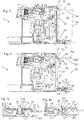
- FIG. 1 to 4a illustrates an exemplary embodiment of a beverage machine 1 according to the invention.
- Machine 1 includes: a beverage processing module 10 having a liquid inlet 11 and a module fastening arrangement 12,13,15; and a liquid supply tank 30 having a liquid outlet 31 and a tank fastening arrangement 32,33,35, e.g. a tank 30 for supplying water.
- Tank outlet 31 can be fluidically connected to module inlet 11 and disconnected therefrom, as illustrated in Figs 2a to 4a .
- Fastening arrangements 12,13,15;32,33,35 comprise a female connector 12 and a male connector 32 cooperating with female connector 12 for reversibly assembling module 10 and tank 30.
- a male tank connector 32 cooperates with a female module connector 12 or a male module connector cooperates with a female tank connector.
- Tank 30 can have a pivot area 30' about which tank 30 is pivoted into and out of a fastening position in which tank 30 and module 10 are fastened together via the fastening arrangement 12,13,15;32,33,35. See Figs 2a , 3a and 4a .
- Fastening arrangements 12,13,15;32,33,35 further comprise at least one pair made of a support surface 13,35 and a resilient member 33,15 that cooperate together for urging male connector 32 into female connector 12 so as to fasten the tank 30 to the module.
- the pair comprises as module support surface 13 and a tank resilient member 33 or a tank support surface 35 and a module resilient member 15.
- Female and male connectors 12,32 of the pair can have one or more degrees of freedom F1,F2 when tank 30 is assembled to module 10, such degree(s) of freedom F1,F2 being in general opposition to a direction U into which tank 30 is urged by resilient member 33,15 cooperating with support surface 13,35. See Fig. 4 .
- At least one of such pair can be made of a support surface 13,35 and a resilient member 33,15 configured to be urged together when tank 30 is assembled to module 10.
- Support surface 35 may form an outer face of tank 30 and resilient member 15 may form a support arm or panel, such as a foot, projecting from a main body 10' of module 10 and extending across tank 30 at outer face 35.
- a support arm or panel can extend across a predominant part of the tank 30 at outer face 35. See Figs. 2a , 3a and 4a .
- the support surface can form an outer face of the module and the resilient member can form a support arm or panel, such as a foot, projecting from a main body of the tank and extending across the module at the outer face.
- a support arm or panel such as a foot
- such support arm or panel may extend across a predominant part of the module at the outer face.
- At least one of such pair can be made of a support surface 13 and a resilient member 33 configured to urge apart at support surface 13 and resilient member 33: an outer face 34 of tank 30 and an outer face 14 of module 10 that faces outer tank face 34.
- Resilient member 33 may include an urging element 331, such as a ram 331 mounted on a spring 332, movably mounted at one 34 of outer faces 14,34.
- Support surface 13 can be fixedly or integrally or movably mounted at the other 14 of outer faces 14,34. See Figs. 2a , 3a and 4a .
- Resilient member 33 can be movably mounted to or in outlet 31 and support surface 13 can be fixedly or integrally or movably mounted in or to inlet 11. See Figs. 2a , 3a and 4a .
- Resilient member may be movably mounted to or in the inlet and support surface may be fixedly or integrally or movably mounted in or to the outlet.
- Resilient member 33 and support surface 13 can be formed as or within a male-female mechanical connection arrangement between module 10 and tank 30, e.g. a mechanical connection formed by inlet 11 and outlet 31. See Figs. 2a , 3a and 4a .
- Female connector 12 can be formed as a recessed part and male connector 32 can be formed as a protruding part having a shape generally complementary to the recessed part.
- Female connector 12 and male connector 32 can be formed as a hook part and a catch part. See Figs 1a, 2 and 4 .
- Machine 1 can include a lid 36 at an opening 36' of tank 30. See Figs 1, 1a and 2 .
- Lid 36 may be moved between a position covering opening 36' and a position uncovering opening 36'.
- lid 36 and tank 30 have a fastening arrangement for fastening lid 36 in the covering position.
- lid-tank fastening arrangement includes lid flange 361' projecting and fastened in or around a tank rim 361' delimiting opening 36' and/or a lid and a tank in a hook and hook-retainer configuration, when lid 36 is in the covering position.
- Lid 36 can be permanently or temporarily assembled to tank 30.
- Lid 36 may include one 32 of female connector 12 and male connector 32 for cooperating with the other 32 of female connector 12 and male connector 32 comprised by module 10 so as to fasten tank 30 with lid 36 to module 10.
- Male connector 32 can be formed by a hinge of lid 36 and/or by a hinge holder of tank 30, e.g. end portions of the hinge or hinge holder. See Figs 1, 1a and 4 .
- Female and male connectors can be assembled by moving the lid, e.g. pivoting the lid, from the open to the closed position and being disassembled by moving the lid, e.g. pivoting the lid, from the closed to the open position.
- Tank 30 can include an upright wall 37 delimiting a liquid storage cavity, an outside face of upright wall 37 forming or being fixed to one 32 of female connector 12 and male connector 32 for cooperating with the other 12 of female connector 12 and male connector 32.
- the other 12 of female connector 12 and male connector 32 is formed or fixed to an outside face of an upright wall 17 of module 10.
- Female and male connectors 12,32 can be located at one end of tank 30 and said at least one pair 13,35;33,15 can be locate at a generally opposite end of tank 30 when tank 30 is assembled to module 10. See Fig. 4 .
- Female connector 12 and male connector 32 may be located at one face 36,37 of tank 30 and said at least one pair 13, 35; 33, 15 can be locate at an another face 34 of tank 30 when tank 30 is assembled to module 10.
- Such another face 34 being for instance adjacent to or opposite to said one face 36,3).
- such another face 34 being a bottom face of tank 30 and such one face 36, 37 being a side face 37 or a top face 36 of tank 30.
- Module 10 may include a beverage outlet 20 to which liquid inlet 11 is fluidically connected.
- Module 10 can have a platform 19 for supporting tank 30 and or extending under a bottom 35 of tank 30 when tank 30 is assembled to module 10.
- platform 19 comprises the inlet.
- Module 10 may have an ingredient inlet 21 for supplying an ingredient, such as an ingredient contained in a capsule, to be processed with liquid from tank 30 via liquid inlet 11.
- Module 10 can include a support 22 for placing a user-recipient, e.g. a cup or a mug, for collecting the beverage delivered by outlet 20.
- a user-recipient e.g. a cup or a mug
- Module 10 may have an actuator, such as a handle 23 or a motor, for actuating module 10 for receiving in and/or evacuating from module 10 an ingredient, such as an ingredient contained in a capsule.
- an actuator such as a handle 23 or a motor
- Module 10 can comprise a pump 24 for pumping liquid from outlet 31 to beverage outlet 20.
- Module 10 can include a mixing chamber 25 in fluid connection with inlet 11 and beverage outlet 20 for mixing liquid with an ingredient such as an ingredient contained in a capsule.
- mixing chamber 25 is actuated e.g. by a handle 23 between an open position for inserting into and/or removing from chamber 25 the ingredient and a closed position for mixing the ingredient and liquid and for subsequent dispensing via beverage outlet 20.
- Module 10 can have a thermal conditioner 26, such as a heater and/or a cooler, for thermally conditioning liquid supplied from inlet 11 to beverage outlet 20.
- a thermal conditioner 26 such as a heater and/or a cooler
- Module 10 can comprise a machine control unit such as a control unit with a user-interface 27.
- Module 10 can include a waste collector 28, such as a collector of residual liquid and/or residual ingredient e.g. contained in a capsule.
- waste collector 28 is removable from module 10 for servicing.
- Tank 30 may have a valve 331,332 for allowing a passage of liquid via the tank's outlet 31 when the tank's outlet 31 is connected to the module's inlet 11 and for preventing the passage of liquid via the tank's outlet 31 when the tank's outlet 31 is disconnected from the module's inlet 11.
- valve 331,332 forms part of the above at least one pair 33, such as forming the urging element 331 and optional spring 332 as mentioned above.
- Tank 30 can have a bottom 34 and one or more peripheral upright sidewalls 37 delimiting a liquid storage cavity 38.
- Tank 30 may have an opening 36' delimited by a rim 361' for filling a storage cavity 38 of the tank with liquid, such as water.
- Tank 30 can have a foot 39 on which tank 30 can rest when filled with liquid before and/or upon assembly of tank 30 to module 10.
- Tank 30 may include a passage 39, e.g. a notch or through-opening, for passing an electric cord 18 to module 10, such as an opening in a foot 39' of tank 30.
- a passage 39 e.g. a notch or through-opening, for passing an electric cord 18 to module 10, such as an opening in a foot 39' of tank 30.
Landscapes
- Engineering & Computer Science (AREA)
- Food Science & Technology (AREA)
- Mechanical Engineering (AREA)
- Apparatus For Making Beverages (AREA)
- Devices For Dispensing Beverages (AREA)
Claims (15)
- Getränkemaschine (1), umfassend:- einem Getränkeverarbeitungsmodul (10) mit einem Flüssigkeitseinlass (11) und einer Modulbefestigungsanordnung (12, 13, 15); und- einem Flüssigkeitszufuhrtank (30) mit einem Flüssigkeitsauslass (31) und einer Tankbefestigungsanordnung (32, 33, 35), z. B. ein Tank (30) zum Zuführen von Wasser,wobei der Auslass (31) fluidisch mit dem Einlass (11) verbindbar und davon trennbar ist,
wobei die Befestigungsanordnungen (12, 13, 15; 32, 33, 35) einen aufnehmenden Verbinder (12) und einen eindringenden Verbinder (32), der mit dem aufnehmenden Verbinder (12) zusammenwirkt, umfassen, um das Modul (10) und den Tank (30) umkehrbar zusammenzubauen, wie etwa einen eindringenden Tankverbinder (32), der mit einem aufnehmenden Modulverbinder (12) zusammenwirkt, oder einen eindringenden Modulverbinder, der mit einem aufnehmenden Tankverbinder zusammenwirkt, wobei der Tank (30) wahlweise einen Schwenkbereich (30') aufweist, um den der Tank (30) in eine Befestigungsposition eingeschwenkt wird, in der der Tank (30) und das Modul (10) mittels der Befestigungsanordnung (12, 13, 15; 32, 33, 35) aneinander befestigt sind, und aus ihr heraus geschwenkt wird,
wobei die Befestigungsanordnungen (12, 13, 15; 32, 33, 35) ferner mindestens ein Paar einer Stützfläche (13, 35) und eines elastischen Elements (33, 15), die miteinander zusammenwirken, umfassen, wie etwa eine Modulstützfläche (13) und ein elastisches Tankelement (33) oder eine Tankstützfläche (35) und ein elastisches Modulelement (15),
dadurch gekennzeichnet, dass die Stützfläche (13, 35) und das elastische Element (33, 15) zusammenwirken, um den eindringenden Verbinder (32) in den aufnehmenden Verbinder (12) zu drängen, um so den Tank (30) an dem Modul zu befestigen, wobei der aufnehmende und eindringende Verbinder (12, 32) wahlweise ein oder mehrere Freiheitsgrade (F1, F2) aufweisen, wenn der Tank (30) an das Modul (10) angebaut wird, wobei der/die Freiheitsgrad(e) (F1, F2) im Allgemeinen entgegengesetzt zu einer Richtung (U) ist/sind, in die der Tank (30) durch das elastische Element (33, 15) gedrängt wird, das mit der Stützfläche (13, 35) zusammenwirkt. - Maschine nach Anspruch 1, wobei das mindestens eine Paar eine Stützfläche (13, 35) und ein elastisches Element (33, 15) umfasst, die dazu konfiguriert sind, zusammengedrängt zu werden, wenn der Tank (30) an das Modul (10) angebaut wird.
- Maschine nach Anspruch 2, wobei die Stützfläche (35) eine Außenseite des Tanks (30) bildet und das elastische Element (15) einen Stützarm oder eine Stützplatte, wie einen Fuß, bildet, der aus einem Hauptkörper (10') des Moduls (10) vorsteht und sich über den Tank (30) an der Außenseite (35) erstreckt, wie etwa über einen überwiegenden Teil des Tanks (30) an der Außenseite (35), oder wobei die Stützfläche eine Außenseite des Moduls bildet und das elastische Element einen Stützarm oder eine Stützplatte, wie einen Fuß, bildet, der aus einem Hauptkörper des Tanks vorsteht und sich über das Modul an der Außenseite erstreckt, wie etwa über einen überwiegenden Teil des Moduls an der Außenseite.
- Maschine nach einem der vorstehenden Ansprüche, wobei das mindestens eine Paar eine Stützfläche (13) und ein elastisches Element (33) umfasst, die dazu konfiguriert sind, an der Stützfläche (13) und dem elastischen Element (33) Folgendes auseinanderzudrängen: eine Außenseite (34) des Tanks (30) und eine Außenseite (14) des Moduls (10), die der Tankaußenseite (34) zugewandt ist.
- Maschine nach Anspruch 4, wobei das elastische Element (33) ein drängendes Element (331) umfasst, wie etwa einen an einer Feder (332) montierten Stößel (331), der beweglich an einer (34) der Außenseiten (14, 34) montiert ist, und wobei die Stützfläche (13) fest oder einstückig oder beweglich an der anderen (14) der Außenseiten (14, 34) montiert ist.
- Maschine nach Anspruch 4 oder 5, wobei das elastische Element (33) beweglich an oder in dem Auslass (31) montiert ist und die Stützfläche (13) fest oder einstückig oder beweglich in oder an dem Einlass (11) montiert ist oder wobei das elastische Element beweglich an oder in dem Einlass montiert ist und die Stützfläche fest oder einstückig oder beweglich in oder an dem Auslass montiert ist.
- Maschine nach einem der vorstehenden Ansprüche, wobei das elastische Element (33) und die Stützfläche (13) als oder innerhalb einer mechanischen Eindringungs-Aufnahme-Verbindungsanordnung zwischen dem Modul (10) und dem Tank (30) gebildet sind, z. B. eine mechanische Verbindung, die durch den Einlass (11) und den Auslass (31) gebildet ist.
- Maschine nach einem der vorstehenden Ansprüche, wobei der aufnehmende Verbinder (12) als ein ausgesparter Teil gebildet ist und der eindringende Verbinder (32) als ein herausragender Teil mit einer Form, die im Allgemeinen komplementär zu dem ausgesparten Teil ist, gebildet ist.
- Maschine nach einem der vorstehenden Ansprüche, wobei der aufnehmende Verbinder (12) und der eindringende Verbinder (32) als ein Hakenteil und ein Fangteil gebildet sind.
- Maschine nach einem der vorstehenden Ansprüche, die einen Deckel (36) an einer Öffnung (36') des Tanks (30) umfasst und der zwischen einer Position zum Abdecken der Öffnung und einer Position zum Freilegen der Öffnung beweglich ist, wobei der Deckel (36) und der Tank (30) wahlweise eine Befestigungsanordnung zum Befestigen des Deckels (36) in der Abdeckposition, wie einen Deckelflansch (361'), aufweisen, der vorsteht und in oder um einen Tankrand (361') befestigt ist, der die Öffnung (36') und/oder einen Deckel und einen Tank in einer Haken und Hakenhalterungsausgestaltung begrenzt, wenn der Deckel (36) in der Abdeckposition ist.
- Maschine nach Anspruch 10, wobei der Deckel (36) dauerhaft oder vorübergehend an dem Tank (30) angebaut ist und wobei der Deckel (36) einen (32) des aufnehmenden Verbinders (12) und des eindringenden Verbinders (12, 32) umfasst, um mit dem anderen (32) des aufnehmenden Verbinders (12) und des eindringenden Verbinders (12, 32) zusammenzuwirken, der von dem Modul (10) umfasst ist, um so den Tank (30) mit dem Deckel (36) an dem Modul (10) zu befestigen, wobei wahlweise:- der eindringende Verbinder (32) durch ein Scharnier des Deckels (36) und/oder durch einen Scharnierhalter des Tanks (30) gebildet ist, z. B. Endabschnitte des Scharniers oder des Scharnierhalters; oder- die aufnehmenden und eindringenden Verbinder durch Bewegen des Deckels, z. B. Schwenken des Deckels, von der offenen zu der geschlossenen Position zusammengebaut werden und durch Bewegen des Deckels, z. B. Schwenken des Deckels, von der geschlossenen zu der offenen Position auseinandergebaut werden.
- Maschine nach einem der vorstehenden Ansprüche, wobei der Tank (10) eine aufrechte Wand (37) umfasst, die einen Flüssigkeitsspeicherhohlraum begrenzt, wobei eine Außenseite der aufrechten Wand (37) einen (32) des aufnehmenden Verbinders (12) und des eindringenden Verbinders (32) bildet oder an ihm befestigt ist, um mit dem anderen (12) des aufnehmenden Verbinders (12) und des eindringenden Verbinders (32) zusammenzuwirken, wobei der andere (12) des aufnehmenden Verbinders (12) und des eindringenden Verbinders (32) wahlweise an einer Außenseite einer aufrechten Wand (17) des Moduls (10) gebildet oder befestigt ist.
- Maschine nach einem der vorstehenden Ansprüche, wobei sich der aufnehmende Verbinder (12) und der eindringende Verbinder (32) an einem Ende des Tanks (30) befinden und wobei sich das mindestens eine Paar (13, 35; 33, 15) an einem im Allgemeinen entgegengesetzten Ende des Tanks (30) befindet, wenn der Tank (30) an dem Modul (10) angebaut ist.
- Maschine nach einem der vorstehenden Ansprüche, wobei sich der aufnehmende Verbinder (12) und der eindringende Verbinder (32) an einer Seite (36, 37) des Tanks (30) befinden und wobei sich das mindestens eine Paar (13, 35; 33,15) an einer anderen Seite (34) des Tanks (30) befindet, wenn der Tank (30) an dem Modul (10) angebaut ist, wobei die andere Seite (34) wahlweise benachbart oder entgegengesetzt zu der einen Seite (36, 37) ist, wobei z. B. die andere Seite (34) eine Unterseite des Tanks und die eine Seite (36, 37) eine Seitenfläche (37) oder eine Oberseite (36) des Tanks ist.
- Maschine nach einem der vorstehenden Ansprüche, wobei das Modul (10) einen Getränkeauslass (20) umfasst, mit dem der Flüssigkeitseinlass (11) fluidisch verbunden ist, wobei das Modul (10) wahlweise ferner mindestens eines von Folgendem umfasst:- eine Plattform (19) zum Stützen des Tanks (30) und/oder sich Erstrecken unter einem Boden (35) des Tanks (30), wenn der Tank (30) an dem Modul (10) angebaut ist, wobei die Plattform (19) wahlweise den Einlass umfasst;- einen Inhaltsstoffeinlass (21) zum Zuführen eines Inhaltsstoffs, wie etwa eines in einer Kapsel enthaltenen Inhaltsstoffs, der mit Flüssigkeit aus dem Tank (30) über den Flüssigkeitseinlass (11) zu verarbeiten ist;- einen Träger (22) zum Platzieren eines Benutzerbehälters, z. B. eine Tasse oder ein Becher, zum Aufnehmen des Getränks, das durch den Auslass (20) ausgegeben wird;- ein Stellglied, wie etwa einen Griff (23) oder einen Motor, zum Betätigen des Moduls (10), um einen Inhaltsstoff, wie etwa einen in einer Kapsel enthaltenen Inhaltsstoff, in das Modul (10) aufzunehmen und/oder daraus zu entleeren;- eine Pumpe (24) zum Pumpen der Flüssigkeit von dem Auslass (31) zu dem Getränkeauslass (20);- eine Mischkammer (25) in Fluidverbindung mit dem Einlass (11) und dem Getränkeauslass (20) zum Mischen der Flüssigkeit mit einem Inhaltsstoff, wie etwa einen Inhaltsstoff, der in einer Kapsel enthalten ist, wobei die Mischkammer (25) wahlweise durch z. B. einen Griff (23) zwischen einer offenen Position zum Einführen des Inhaltsstoffs in und/oder zum Entfernen des Inhaltsstoffs aus der Kammer (25) und einer geschlossenen Position zum Mischen des Inhaltsstoffs und der Flüssigkeit zum Ausgeben über den Getränkeauslass (20) betätigt wird;- einen Wärmekonditionierer (26), wie etwa eine Heiz- und/oder Kühleinrichtung, zur Wärmekonditionierung der Flüssigkeit, die von dem Einlass (11) zu dem Getränkeauslass (20) zugeführt wird;- eine Maschinensteuereinheit, wie etwa eine Steuereinheit mit einer Benutzerschnittstelle (27); und- einen Abfallsammler (28), wie einen Sammler von Restflüssigkeit und/oder Restinhaltsstoff, der z. B. in einer Kapsel enthalten ist, wobei der Abfallsammler (28) wahlweise zur Wartung vom Modul (10) entfernbar ist,und/oder der Tank (30) mindestens eines von Folgendem umfasst:- ein Ventil (331, 332), um einen Durchlass von Flüssigkeit über den Auslass (31) des Tanks zu ermöglichen, wenn der Auslass (31) des Tanks mit dem Einlass (11) des Moduls verbunden ist, und um den Durchlass von Flüssigkeit über den Auslass (31) des Tanks zu verhindern, wenn der Auslass (31) des Tanks von dem Einlass (11) des Moduls getrennt ist, wobei das Ventil (331, 332) zum Beispiel einen Teil des mindestens einen Paares (33) bildet, wie etwa das Bilden des drängenden Elements (331) und wahlweise der Feder (332) nach Anspruch 5;- einen Boden (34) und eine oder mehrere periphere aufrechte Seitenwände (37), die einen Flüssigkeitsspeicherhohlraum (38) begrenzen;- eine Öffnung (36'), die durch einen Rand (361') begrenzt ist, um einen Speicherhohlraum (38) des Tanks mit Flüssigkeit, wie Wasser, zu füllen;- einen Fuß (39), auf dem der Tank (30) ruhen kann, wenn er vor und/oder nach dem Anbau des Tanks (30) an das Modul (10) mit Flüssigkeit gefüllt wird; und- einen Durchgang (39), wie etwa eine Nut oder Durchgangsöffnung, zum Leiten eines elektrischen Kabels (18) zu dem Modul (10), wie eine Öffnung in einem Fuß (39') des Tanks (30).
Applications Claiming Priority (2)
| Application Number | Priority Date | Filing Date | Title |
|---|---|---|---|
| EP15194020 | 2015-11-11 | ||
| PCT/EP2016/077076 WO2017081055A1 (en) | 2015-11-11 | 2016-11-09 | Easy connection of a liquid tank to a beverage machine |
Publications (2)
| Publication Number | Publication Date |
|---|---|
| EP3373779A1 EP3373779A1 (de) | 2018-09-19 |
| EP3373779B1 true EP3373779B1 (de) | 2020-12-23 |
Family
ID=54539948
Family Applications (1)
| Application Number | Title | Priority Date | Filing Date |
|---|---|---|---|
| EP16791629.5A Active EP3373779B1 (de) | 2015-11-11 | 2016-11-09 | Leichtes anschliessen eines flüssigtanks an einem getränkeautomaten |
Country Status (9)
| Country | Link |
|---|---|
| US (1) | US11284738B2 (de) |
| EP (1) | EP3373779B1 (de) |
| JP (1) | JP6910352B2 (de) |
| CN (1) | CN108348093B (de) |
| AU (1) | AU2016353456B2 (de) |
| ES (1) | ES2847752T3 (de) |
| PT (1) | PT3373779T (de) |
| RU (1) | RU2713330C2 (de) |
| WO (1) | WO2017081055A1 (de) |
Families Citing this family (13)
| Publication number | Priority date | Publication date | Assignee | Title |
|---|---|---|---|---|
| ZAA201801401S (en) * | 2018-03-09 | 2019-08-28 | Nestle Sa | Beverage dispensers |
| USD865427S1 (en) * | 2018-03-09 | 2019-11-05 | Société´des Produits Nestlé´S.A. | Beverage dispenser |
| USD877552S1 (en) * | 2018-03-26 | 2020-03-10 | Société des Produits Nestlé S.A. | Beverage dispenser |
| JP7382398B2 (ja) | 2018-09-27 | 2023-11-16 | ソシエテ・デ・プロデュイ・ネスレ・エス・アー | 飲料マシンの適応サービスユニット |
| EP3628195A1 (de) | 2018-09-27 | 2020-04-01 | Société des Produits Nestlé S.A. | Getränkeherstellungsmaschine mit behältererkennung |
| RU2758622C2 (ru) * | 2019-10-14 | 2021-11-01 | Общество с ограниченной ответственностью "ЭР ЛАБ" | Устройство для автоматического набора воды с одновременным измерением веса |
| US12171361B2 (en) | 2020-12-30 | 2024-12-24 | Sharkninja Operating Llc | Hybrid receptacle beverage brewing system |
| US20240398150A1 (en) | 2021-10-08 | 2024-12-05 | Societe Des Produits Nestle S.A. | Beverage preparation machine with simple ergonomic opening-closure |
| CA3233465A1 (en) | 2021-10-13 | 2023-04-20 | Laurent LAGOUCHE | Ergonomic beverage machine |
| USD1048792S1 (en) | 2023-04-12 | 2024-10-29 | Sharkninja Operating Llc | Coffee machine |
| US12005408B1 (en) | 2023-04-14 | 2024-06-11 | Sharkninja Operating Llc | Mixing funnel |
| USD1048793S1 (en) | 2023-05-02 | 2024-10-29 | Sharkninja Operating Llc | Coffee machine |
| WO2024254837A1 (en) | 2023-06-16 | 2024-12-19 | Sharkninja Operating Llc | Carbonation mixing nozzles |
Family Cites Families (95)
| Publication number | Priority date | Publication date | Assignee | Title |
|---|---|---|---|---|
| CH587647A5 (de) * | 1975-07-11 | 1977-05-13 | Icomag Trust Reg | |
| JPS605871Y2 (ja) * | 1979-11-22 | 1985-02-23 | 三洋電機株式会社 | 蓋体取付装置 |
| JPS605888B2 (ja) | 1979-11-30 | 1985-02-14 | 株式会社安川電機 | 交流電動機の瞬時トルク検出方式 |
| EP0049686B1 (de) | 1980-10-02 | 1984-06-06 | Ciba-Geigy Ag | Hydrochinon-Derivate, deren Herstellung und Verwendung in photographischen Materialien |
| JPS5799640U (de) * | 1980-12-09 | 1982-06-18 | ||
| DE19504839C1 (de) * | 1995-02-14 | 1996-04-04 | Braun Ag | Kaltwasservorratsbehälter für eine elektrische Haushaltsbrühgetränkemaschine |
| US6459854B1 (en) | 2000-01-24 | 2002-10-01 | Nestec S.A. | Process and module for heating liquid |
| FR2806606B1 (fr) | 2000-03-24 | 2002-10-25 | Moulinex Sa | Machine a cafe electrique avec reservoir d'eau pivotant |
| PT1153561E (pt) | 2000-05-09 | 2005-09-30 | Nestle Sa | Dispositivo para a extraccao de uma substancia |
| EP1208782B1 (de) | 2000-11-28 | 2004-08-25 | Societe Des Produits Nestle S.A. | Perkolationsvorrichtung |
| DE20105672U1 (de) | 2001-03-31 | 2001-09-13 | Eugster/Frismag Ag, Romanshorn | Espressobrüheinrichtung |
| AU2002242670B2 (en) | 2002-01-10 | 2007-01-25 | Societe Des Produits Nestle S.A. | Automatic device for the extraction of a substance |
| FR2841116B1 (fr) * | 2002-06-19 | 2004-11-26 | Seb Sa | Cafetiere du type expresso a reservoir d'eau amovible |
| DE60227248D1 (de) | 2002-07-12 | 2008-08-07 | Nestec Sa | Vorrichtung zum Erhitzen einer Flüssigkeit |
| JP3974047B2 (ja) | 2003-02-04 | 2007-09-12 | 象印マホービン株式会社 | コーヒーメーカーの水タンク取付け構造 |
| ATE316349T1 (de) | 2003-02-07 | 2006-02-15 | Nestec Sa | Linearextraktionsmodul zur zubereitung von einem getränk aus einer kartusche |
| DE20302410U1 (de) | 2003-02-13 | 2004-06-24 | Nestec S.A. | Kapselmagazineinheit mit Kapselmagazineinheitaufnahmeeinrichtung, insbesondere einer Espressomaschine |
| EP1495702A1 (de) | 2003-07-10 | 2005-01-12 | Nestec S.A. | Vorrichtung zur Extraktion einer Kartusche |
| JP4695091B2 (ja) | 2003-11-22 | 2011-06-08 | ネステク ソシエテ アノニム | 飲料又は類似した製品を調合するための加圧気体供給を備える移動式又は携帯型装置 |
| US7165488B2 (en) | 2003-12-12 | 2007-01-23 | Keurig, Incorporated | Brew chamber for a single serve beverage brewer |
| EP1634520A1 (de) | 2004-09-13 | 2006-03-15 | Nestec S.A. | Vorrichtung zur Heizung einer Flüssigkeit und Verfahren zum Erhitzen einer Flüssigkeit |
| DE102004046455A1 (de) * | 2004-09-24 | 2006-04-13 | BSH Bosch und Siemens Hausgeräte GmbH | Kaffeemaschine und Steuerungsverfahren dafür |
| ES2360218T3 (es) | 2004-11-11 | 2011-06-01 | Nestec S.A. | Cabezal de mezclado auto-limpiable para producir una mezcla a base de leche y máquinas de producción de bebidas comprendiendo dicho cabezal de mezclado. |
| ES2306427T3 (es) | 2005-03-29 | 2008-11-01 | Nestec S.A. | Maquina autonoma para distribuir bebidas. |
| DE602005007475D1 (de) | 2005-06-07 | 2008-07-24 | Nestec Sa | Getränkemaschine mit Auffangwanne für Behälter unterschiedlicher Höhe |
| DK1764014T5 (da) | 2005-09-20 | 2009-07-13 | Nestec Sa | Termoblokbaseret drikkevarefremstillingsindretning med brygkamre |
| PL1767129T3 (pl) | 2005-09-27 | 2009-04-30 | Nestec Sa | Moduł ekstrakcyjny dla urządzenia do wytwarzania napoju na bazie kapsułki |
| DE202006002678U1 (de) | 2006-02-17 | 2006-04-20 | Eugster/Frismag Ag | Kaffeemaschine zur Zubereitung eines Kaffeegetränks mittels abgepackter, vorportionierter Kaffeepouches |
| FR2898028B1 (fr) | 2006-03-01 | 2008-05-16 | Seb Sa | Machine a infuser comprenant un dispositif d'ejection du produit infuse |
| US7513192B2 (en) | 2006-03-23 | 2009-04-07 | Keurig, Incorporated | Beverage forming device with opening/closing mechanism for a beverage cartridge receiver |
| PT1859713E (pt) | 2006-05-24 | 2009-09-24 | Nestec Sa | Dispositivo de infusão para cápsula com mecanismo de fecho de relação de transmissão variável |
| EP1864598B1 (de) | 2006-06-09 | 2011-02-16 | Nestec S.A. | Modulares Getränk-Herstellungs-System mit einer Dockingstation |
| EP2189088B1 (de) | 2006-06-16 | 2013-05-15 | Nestec S.A. | Getränkeautomat mit Auflagesystem und Tropffänger für Behälter verschiedener Größen |
| PT1878368E (pt) | 2006-07-11 | 2009-07-28 | Nestec Sa | Máquina de produção de bebidas com bloco funcional e base de apoio |
| EP1992263B2 (de) | 2007-05-16 | 2016-10-12 | Nestec S.A. | Getränkeproduktionsmodul und Verfahren für den Betrieb eines Getränkeproduktionsmoduls |
| CN201076369Y (zh) | 2007-07-24 | 2008-06-25 | 宁波圣开纳电器有限公司 | 一种可用自来水供水的咖啡机 |
| EP2027798A1 (de) | 2007-08-20 | 2009-02-25 | Nestec S.A. | Getränkeproduktionsmodul und Verfahren für den Betrieb eines Getränkeproduktionsmoduls |
| CL2008002963A1 (es) | 2007-10-04 | 2010-01-22 | Nestec Sa | Dispositivo calentador para una maquina para la preparacion de alimento liquido o bebida, que comprende una unidad termica con una masa metalica, a traves de la cual circula el liquido, y acumula calor y lo suministra al liquido, y tiene uno o mas componentes electricos asegurados en forma rigida a la unidad termica; y maquina. |
| AU2008306060C1 (en) | 2007-10-04 | 2015-08-27 | Société des Produits Nestlé S.A. | Beverage brewing unit |
| WO2009043851A2 (en) | 2007-10-04 | 2009-04-09 | Nestec S.A. | Integrated heater for a beverage preparation device |
| EP2227121B1 (de) | 2007-12-12 | 2011-04-13 | Nestec S.A. | Behältnis für verbrauchte kapseln oder pods für maschinen zur zubereitung von flüssignahrungsmitteln oder getränken |
| EP2070454B1 (de) | 2007-12-12 | 2015-07-15 | Nestec S.A. | Modulare Herstellung von Getränkeherstellungsmaschinen |
| EP2082669A2 (de) | 2008-01-25 | 2009-07-29 | Nestec S.A. | Hybridvorrichtung für die Getränkezubereitung |
| CN102056524B (zh) * | 2008-05-08 | 2013-08-28 | 雀巢产品技术援助有限公司 | 饮料生产设备 |
| RU2463245C2 (ru) | 2008-05-08 | 2012-10-10 | Нестек С.А. | Средство для установки уровня наполнения чашки, используемое с устройством для разлива напитков |
| PT2296515E (pt) | 2008-05-28 | 2012-08-24 | Nestec Sa | Bomba para dispositivos de preparação de bebidas líquidas |
| CA2726058A1 (en) | 2008-07-09 | 2010-01-14 | Nestec S.A. | Ergonomic interface screen for a beverage machine |
| DK2317898T3 (da) | 2008-07-14 | 2012-10-15 | Nestec Sa | Vandcirkulationssystem til en driktilberedningsindretning |
| JP5608647B2 (ja) | 2008-08-08 | 2014-10-15 | ネステク ソシエテ アノニム | 持ち運びハンドルおよび設定変更可能な外観ならびに副次的機能を伴う飲料装置 |
| CA2736927A1 (en) | 2008-10-03 | 2010-04-08 | Nestec S.A. | User-friendly interface for a beverage machine |
| EP2228633B1 (de) | 2009-03-10 | 2017-07-05 | Nestec S.A. | Optischer Füllstandssensor für eine Getränkemaschine |
| RU2534915C2 (ru) | 2009-03-23 | 2014-12-10 | Нестек С.А. | Крепление насоса в аппарате для приготовления напитка |
| EP2427085B1 (de) | 2009-05-06 | 2016-09-21 | Nestec S.A. | Methode zur herstellung von getränkemaschinen mit vereinfachter bedienung |
| IN2012DN01502A (de) | 2009-08-19 | 2015-05-22 | Nestec Sa | |
| WO2011026853A1 (en) | 2009-09-02 | 2011-03-10 | Nestec S.A. | Beverage machine for a network |
| PT2475291E (pt) | 2009-09-09 | 2015-05-11 | Nestec Sa | Máquina de bebidas numa rede |
| WO2011083103A2 (en) | 2010-01-06 | 2011-07-14 | Nestec S.A. | Vibration proof water tank of a beverage machine |
| EP2525693B2 (de) | 2010-01-21 | 2018-01-10 | Nestec S.A. | Getränkeautomat mit abnehmbarem flüssigkeitsversorgungsbehälter |
| EP2353469A1 (de) | 2010-02-03 | 2011-08-10 | Nestec S.A. | Getränkeherstellungsmaschine für große Getränkemengen |
| US20120328456A1 (en) | 2010-03-05 | 2012-12-27 | Nestec S.A. | Reduction of pump nuisance |
| AU2011254528B2 (en) | 2010-05-21 | 2015-04-23 | Société des Produits Nestlé S.A. | Ergonomic dispenser interface |
| PT2571404E (pt) | 2010-05-21 | 2014-05-06 | Nestec Sa | Manípulo ergonómico e interface de utilizador |
| WO2011144723A1 (en) | 2010-05-21 | 2011-11-24 | Nestec S.A. | Beverage machine with ergonomic water management |
| EP2579754B1 (de) | 2010-06-09 | 2016-01-06 | Nestec S.A. | Ergonomische serviceanordnung für eine getränkemaschine |
| AU2011267130B2 (en) | 2010-06-17 | 2015-11-19 | Société des Produits Nestlé S.A. | Fast heat-up of a thermal conditioning device e.g. for coffee machine |
| WO2012007313A1 (en) | 2010-07-12 | 2012-01-19 | Nestec S.A. | Secure cup support for beverage machine |
| BR112013001143B1 (pt) | 2010-07-16 | 2020-04-14 | Nestec Sa | máquina de preparação de bebida e método de transformação de uma máquina de preparação de bebida existente |
| MX365198B (es) | 2010-08-27 | 2019-05-27 | Nestec Sa | Unidad de infusion motorizada simple. |
| CA2810451A1 (en) | 2010-09-07 | 2012-03-15 | Nestec S.A. | Ergonomic handle with user-interface |
| JP2013544568A (ja) | 2010-10-27 | 2013-12-19 | ネステク ソシエテ アノニム | 複数の異なる空間環境のための飲料マシン |
| BR112013010542A2 (pt) | 2010-10-27 | 2018-06-19 | Nestec Sa | máquina para bebida com uma saída acessível (conveniente) |
| JP2013544174A (ja) | 2010-12-01 | 2013-12-12 | ネステク ソシエテ アノニム | モータ付き原料用チャンバの為の人間工学的ユーザーインターフェース |
| EP2645914B1 (de) | 2010-12-01 | 2016-07-13 | Nestec S.A. | Getränkeherstellungsmaschine mit tropfensammler |
| BR112013013527A2 (pt) | 2010-12-01 | 2016-10-18 | Nestec Sa | máquina de bebidas tendo uma passagem de cápsula com uma porta |
| CN201977568U (zh) * | 2010-12-24 | 2011-09-21 | 博西华电器(江苏)有限公司 | 咖啡机 |
| KR20130132970A (ko) | 2011-01-03 | 2013-12-05 | 네스텍 소시에테아노님 | 원료 유입구용 커버를 갖춘 음료 머신 |
| RU2013147192A (ru) | 2011-03-23 | 2015-04-27 | Нестек С.А. | Аппарат для приготовления напитков с крышкой для входа для ингредиента |
| JP5799640B2 (ja) | 2011-07-29 | 2015-10-28 | 株式会社村田製作所 | 電歪センサ |
| CA2859057C (en) | 2011-12-30 | 2019-09-03 | Nestec S.A. | A multi-system beverage machine |
| ES2573543T3 (es) | 2012-01-13 | 2016-06-08 | Nestec S.A. | Máquina de bebidas para tazas altas y cortas |
| WO2013104643A1 (en) | 2012-01-13 | 2013-07-18 | Nestec S.A. | Beverage machine with a removable module |
| JP5679223B2 (ja) | 2012-01-24 | 2015-03-04 | 株式会社ダイフク | ラック用の物品はみ出し防止機構 |
| EP2633789A1 (de) | 2012-02-28 | 2013-09-04 | Nestec S.A. | Getränkezubereitungsmaschine mit Tropfenhandhabung |
| EP2658421B1 (de) | 2012-02-28 | 2016-05-11 | Nestec S.A. | Kapselgesteuerte, motorisierte brüheinheit |
| WO2013175346A1 (en) * | 2012-05-23 | 2013-11-28 | Koninklijke Philips N.V. | Beverage producing device with a dual-position water container |
| AU2013329653A1 (en) | 2012-10-09 | 2015-04-16 | Nestec S.A. | Extraction unit with a shiftable multi-size cartridge receiver |
| AU2013329854B2 (en) | 2012-10-09 | 2017-11-16 | Nestec S.A. | Beverage machine |
| BR112015007451A2 (pt) | 2012-10-09 | 2017-07-04 | Nestec Sa | unidade de extração de cartucho de múltiplos tamanhos tendo escorregadores de guiamento |
| CN104869874B (zh) | 2012-10-09 | 2018-01-05 | 雀巢产品技术援助有限公司 | 具有多尺寸料盒腔室的提取单元 |
| CN103767547B (zh) * | 2012-10-18 | 2017-11-07 | 苏州工业园区咖乐美电器有限公司 | 一种用于饮料机的供水装置 |
| EP2908706B1 (de) | 2012-10-19 | 2016-12-14 | Nestec S.A. | Erweiterbare kartuschenaufnahme mit arretierung |
| US10010210B2 (en) | 2012-12-20 | 2018-07-03 | Nestec S.A. | Double ramp for closing a receptacle holder |
| WO2014096122A1 (en) | 2012-12-20 | 2014-06-26 | Nestec S.A. | Variable transmission for closing a receptacle holder |
| CN203693321U (zh) * | 2014-01-02 | 2014-07-09 | 广东顺德雷蒙电器科技有限公司 | 即热式水壶 |
| CN203873569U (zh) * | 2014-04-29 | 2014-10-15 | 张海龙 | 胶囊咖啡机 |
-
2016
- 2016-11-09 AU AU2016353456A patent/AU2016353456B2/en active Active
- 2016-11-09 EP EP16791629.5A patent/EP3373779B1/de active Active
- 2016-11-09 PT PT167916295T patent/PT3373779T/pt unknown
- 2016-11-09 RU RU2018120477A patent/RU2713330C2/ru active
- 2016-11-09 ES ES16791629T patent/ES2847752T3/es active Active
- 2016-11-09 WO PCT/EP2016/077076 patent/WO2017081055A1/en not_active Ceased
- 2016-11-09 JP JP2018522752A patent/JP6910352B2/ja active Active
- 2016-11-09 US US15/774,421 patent/US11284738B2/en active Active
- 2016-11-09 CN CN201680064939.1A patent/CN108348093B/zh active Active
Non-Patent Citations (1)
| Title |
|---|
| None * |
Also Published As
| Publication number | Publication date |
|---|---|
| US11284738B2 (en) | 2022-03-29 |
| EP3373779A1 (de) | 2018-09-19 |
| US20180317697A1 (en) | 2018-11-08 |
| JP2018537160A (ja) | 2018-12-20 |
| RU2713330C2 (ru) | 2020-02-04 |
| ES2847752T3 (es) | 2021-08-03 |
| AU2016353456B2 (en) | 2022-02-24 |
| CA3001089A1 (en) | 2017-05-18 |
| CN108348093B (zh) | 2020-12-15 |
| PT3373779T (pt) | 2021-02-12 |
| RU2018120477A3 (de) | 2019-12-16 |
| AU2016353456A1 (en) | 2018-04-05 |
| RU2018120477A (ru) | 2019-12-16 |
| WO2017081055A1 (en) | 2017-05-18 |
| CN108348093A (zh) | 2018-07-31 |
| JP6910352B2 (ja) | 2021-07-28 |
Similar Documents
| Publication | Publication Date | Title |
|---|---|---|
| EP3373779B1 (de) | Leichtes anschliessen eines flüssigtanks an einem getränkeautomaten | |
| EP2592980B1 (de) | Sicherer becherträger für getränkemaschine | |
| EP2755537B1 (de) | Getränkemaschine mit sauberem mehrfachsystem | |
| AU2015366401B2 (en) | Beverage machine with slidingly connectable cup-support | |
| EP2755536B1 (de) | Sicherer steckverbinder für getränkemaschinen mit mehrfachsystem | |
| CA2821826A1 (en) | Modular beverage dispensing system | |
| CA2845142A1 (en) | Multi-system beverage machine multiple connections | |
| US11744397B2 (en) | Beverage machines with modularity | |
| US20240407586A1 (en) | Ergonomic beverage machine | |
| CA3001089C (en) | Easy connection of a liquid tank to a beverage machine | |
| EP3855988B1 (de) | Adaptive serviceeinheit einer getränkemaschine | |
| EP3687347B1 (de) | Getränkeautomat mit entfernbarem modul |
Legal Events
| Date | Code | Title | Description |
|---|---|---|---|
| STAA | Information on the status of an ep patent application or granted ep patent |
Free format text: STATUS: UNKNOWN |
|
| STAA | Information on the status of an ep patent application or granted ep patent |
Free format text: STATUS: THE INTERNATIONAL PUBLICATION HAS BEEN MADE |
|
| PUAI | Public reference made under article 153(3) epc to a published international application that has entered the european phase |
Free format text: ORIGINAL CODE: 0009012 |
|
| STAA | Information on the status of an ep patent application or granted ep patent |
Free format text: STATUS: REQUEST FOR EXAMINATION WAS MADE |
|
| 17P | Request for examination filed |
Effective date: 20180611 |
|
| AK | Designated contracting states |
Kind code of ref document: A1 Designated state(s): AL AT BE BG CH CY CZ DE DK EE ES FI FR GB GR HR HU IE IS IT LI LT LU LV MC MK MT NL NO PL PT RO RS SE SI SK SM TR |
|
| AX | Request for extension of the european patent |
Extension state: BA ME |
|
| DAV | Request for validation of the european patent (deleted) | ||
| DAX | Request for extension of the european patent (deleted) | ||
| STAA | Information on the status of an ep patent application or granted ep patent |
Free format text: STATUS: EXAMINATION IS IN PROGRESS |
|
| 17Q | First examination report despatched |
Effective date: 20190515 |
|
| RAP1 | Party data changed (applicant data changed or rights of an application transferred) |
Owner name: SOCIETE DES PRODUITS NESTLE S.A. |
|
| GRAP | Despatch of communication of intention to grant a patent |
Free format text: ORIGINAL CODE: EPIDOSNIGR1 |
|
| STAA | Information on the status of an ep patent application or granted ep patent |
Free format text: STATUS: GRANT OF PATENT IS INTENDED |
|
| INTG | Intention to grant announced |
Effective date: 20200713 |
|
| GRAS | Grant fee paid |
Free format text: ORIGINAL CODE: EPIDOSNIGR3 |
|
| GRAA | (expected) grant |
Free format text: ORIGINAL CODE: 0009210 |
|
| STAA | Information on the status of an ep patent application or granted ep patent |
Free format text: STATUS: THE PATENT HAS BEEN GRANTED |
|
| AK | Designated contracting states |
Kind code of ref document: B1 Designated state(s): AL AT BE BG CH CY CZ DE DK EE ES FI FR GB GR HR HU IE IS IT LI LT LU LV MC MK MT NL NO PL PT RO RS SE SI SK SM TR |
|
| REG | Reference to a national code |
Ref country code: GB Ref legal event code: FG4D |
|
| REG | Reference to a national code |
Ref country code: DE Ref legal event code: R096 Ref document number: 602016050286 Country of ref document: DE |
|
| REG | Reference to a national code |
Ref country code: AT Ref legal event code: REF Ref document number: 1346866 Country of ref document: AT Kind code of ref document: T Effective date: 20210115 |
|
| REG | Reference to a national code |
Ref country code: IE Ref legal event code: FG4D |
|
| REG | Reference to a national code |
Ref country code: PT Ref legal event code: SC4A Ref document number: 3373779 Country of ref document: PT Date of ref document: 20210212 Kind code of ref document: T Free format text: AVAILABILITY OF NATIONAL TRANSLATION Effective date: 20210205 |
|
| REG | Reference to a national code |
Ref country code: NL Ref legal event code: FP |
|
| PG25 | Lapsed in a contracting state [announced via postgrant information from national office to epo] |
Ref country code: NO Free format text: LAPSE BECAUSE OF FAILURE TO SUBMIT A TRANSLATION OF THE DESCRIPTION OR TO PAY THE FEE WITHIN THE PRESCRIBED TIME-LIMIT Effective date: 20210323 Ref country code: RS Free format text: LAPSE BECAUSE OF FAILURE TO SUBMIT A TRANSLATION OF THE DESCRIPTION OR TO PAY THE FEE WITHIN THE PRESCRIBED TIME-LIMIT Effective date: 20201223 Ref country code: GR Free format text: LAPSE BECAUSE OF FAILURE TO SUBMIT A TRANSLATION OF THE DESCRIPTION OR TO PAY THE FEE WITHIN THE PRESCRIBED TIME-LIMIT Effective date: 20210324 Ref country code: FI Free format text: LAPSE BECAUSE OF FAILURE TO SUBMIT A TRANSLATION OF THE DESCRIPTION OR TO PAY THE FEE WITHIN THE PRESCRIBED TIME-LIMIT Effective date: 20201223 |
|
| PG25 | Lapsed in a contracting state [announced via postgrant information from national office to epo] |
Ref country code: SE Free format text: LAPSE BECAUSE OF FAILURE TO SUBMIT A TRANSLATION OF THE DESCRIPTION OR TO PAY THE FEE WITHIN THE PRESCRIBED TIME-LIMIT Effective date: 20201223 Ref country code: LV Free format text: LAPSE BECAUSE OF FAILURE TO SUBMIT A TRANSLATION OF THE DESCRIPTION OR TO PAY THE FEE WITHIN THE PRESCRIBED TIME-LIMIT Effective date: 20201223 Ref country code: BG Free format text: LAPSE BECAUSE OF FAILURE TO SUBMIT A TRANSLATION OF THE DESCRIPTION OR TO PAY THE FEE WITHIN THE PRESCRIBED TIME-LIMIT Effective date: 20210323 |
|
| PG25 | Lapsed in a contracting state [announced via postgrant information from national office to epo] |
Ref country code: HR Free format text: LAPSE BECAUSE OF FAILURE TO SUBMIT A TRANSLATION OF THE DESCRIPTION OR TO PAY THE FEE WITHIN THE PRESCRIBED TIME-LIMIT Effective date: 20201223 |
|
| REG | Reference to a national code |
Ref country code: LT Ref legal event code: MG9D |
|
| PG25 | Lapsed in a contracting state [announced via postgrant information from national office to epo] |
Ref country code: RO Free format text: LAPSE BECAUSE OF FAILURE TO SUBMIT A TRANSLATION OF THE DESCRIPTION OR TO PAY THE FEE WITHIN THE PRESCRIBED TIME-LIMIT Effective date: 20201223 Ref country code: SK Free format text: LAPSE BECAUSE OF FAILURE TO SUBMIT A TRANSLATION OF THE DESCRIPTION OR TO PAY THE FEE WITHIN THE PRESCRIBED TIME-LIMIT Effective date: 20201223 Ref country code: SM Free format text: LAPSE BECAUSE OF FAILURE TO SUBMIT A TRANSLATION OF THE DESCRIPTION OR TO PAY THE FEE WITHIN THE PRESCRIBED TIME-LIMIT Effective date: 20201223 Ref country code: LT Free format text: LAPSE BECAUSE OF FAILURE TO SUBMIT A TRANSLATION OF THE DESCRIPTION OR TO PAY THE FEE WITHIN THE PRESCRIBED TIME-LIMIT Effective date: 20201223 Ref country code: CZ Free format text: LAPSE BECAUSE OF FAILURE TO SUBMIT A TRANSLATION OF THE DESCRIPTION OR TO PAY THE FEE WITHIN THE PRESCRIBED TIME-LIMIT Effective date: 20201223 Ref country code: EE Free format text: LAPSE BECAUSE OF FAILURE TO SUBMIT A TRANSLATION OF THE DESCRIPTION OR TO PAY THE FEE WITHIN THE PRESCRIBED TIME-LIMIT Effective date: 20201223 |
|
| REG | Reference to a national code |
Ref country code: ES Ref legal event code: FG2A Ref document number: 2847752 Country of ref document: ES Kind code of ref document: T3 Effective date: 20210803 |
|
| PG25 | Lapsed in a contracting state [announced via postgrant information from national office to epo] |
Ref country code: PL Free format text: LAPSE BECAUSE OF FAILURE TO SUBMIT A TRANSLATION OF THE DESCRIPTION OR TO PAY THE FEE WITHIN THE PRESCRIBED TIME-LIMIT Effective date: 20201223 |
|
| REG | Reference to a national code |
Ref country code: DE Ref legal event code: R097 Ref document number: 602016050286 Country of ref document: DE |
|
| PG25 | Lapsed in a contracting state [announced via postgrant information from national office to epo] |
Ref country code: IS Free format text: LAPSE BECAUSE OF FAILURE TO SUBMIT A TRANSLATION OF THE DESCRIPTION OR TO PAY THE FEE WITHIN THE PRESCRIBED TIME-LIMIT Effective date: 20210423 |
|
| PG25 | Lapsed in a contracting state [announced via postgrant information from national office to epo] |
Ref country code: AL Free format text: LAPSE BECAUSE OF FAILURE TO SUBMIT A TRANSLATION OF THE DESCRIPTION OR TO PAY THE FEE WITHIN THE PRESCRIBED TIME-LIMIT Effective date: 20201223 |
|
| PLBE | No opposition filed within time limit |
Free format text: ORIGINAL CODE: 0009261 |
|
| STAA | Information on the status of an ep patent application or granted ep patent |
Free format text: STATUS: NO OPPOSITION FILED WITHIN TIME LIMIT |
|
| PG25 | Lapsed in a contracting state [announced via postgrant information from national office to epo] |
Ref country code: DK Free format text: LAPSE BECAUSE OF FAILURE TO SUBMIT A TRANSLATION OF THE DESCRIPTION OR TO PAY THE FEE WITHIN THE PRESCRIBED TIME-LIMIT Effective date: 20201223 |
|
| 26N | No opposition filed |
Effective date: 20210924 |
|
| PG25 | Lapsed in a contracting state [announced via postgrant information from national office to epo] |
Ref country code: SI Free format text: LAPSE BECAUSE OF FAILURE TO SUBMIT A TRANSLATION OF THE DESCRIPTION OR TO PAY THE FEE WITHIN THE PRESCRIBED TIME-LIMIT Effective date: 20201223 |
|
| PG25 | Lapsed in a contracting state [announced via postgrant information from national office to epo] |
Ref country code: IS Free format text: LAPSE BECAUSE OF FAILURE TO SUBMIT A TRANSLATION OF THE DESCRIPTION OR TO PAY THE FEE WITHIN THE PRESCRIBED TIME-LIMIT Effective date: 20210423 |
|
| PG25 | Lapsed in a contracting state [announced via postgrant information from national office to epo] |
Ref country code: MC Free format text: LAPSE BECAUSE OF FAILURE TO SUBMIT A TRANSLATION OF THE DESCRIPTION OR TO PAY THE FEE WITHIN THE PRESCRIBED TIME-LIMIT Effective date: 20201223 |
|
| PG25 | Lapsed in a contracting state [announced via postgrant information from national office to epo] |
Ref country code: LU Free format text: LAPSE BECAUSE OF NON-PAYMENT OF DUE FEES Effective date: 20211109 |
|
| PG25 | Lapsed in a contracting state [announced via postgrant information from national office to epo] |
Ref country code: IE Free format text: LAPSE BECAUSE OF NON-PAYMENT OF DUE FEES Effective date: 20211109 |
|
| PG25 | Lapsed in a contracting state [announced via postgrant information from national office to epo] |
Ref country code: HU Free format text: LAPSE BECAUSE OF FAILURE TO SUBMIT A TRANSLATION OF THE DESCRIPTION OR TO PAY THE FEE WITHIN THE PRESCRIBED TIME-LIMIT; INVALID AB INITIO Effective date: 20161109 |
|
| PG25 | Lapsed in a contracting state [announced via postgrant information from national office to epo] |
Ref country code: CY Free format text: LAPSE BECAUSE OF FAILURE TO SUBMIT A TRANSLATION OF THE DESCRIPTION OR TO PAY THE FEE WITHIN THE PRESCRIBED TIME-LIMIT Effective date: 20201223 |
|
| P01 | Opt-out of the competence of the unified patent court (upc) registered |
Effective date: 20230623 |
|
| PG25 | Lapsed in a contracting state [announced via postgrant information from national office to epo] |
Ref country code: MK Free format text: LAPSE BECAUSE OF FAILURE TO SUBMIT A TRANSLATION OF THE DESCRIPTION OR TO PAY THE FEE WITHIN THE PRESCRIBED TIME-LIMIT Effective date: 20201223 |
|
| PG25 | Lapsed in a contracting state [announced via postgrant information from national office to epo] |
Ref country code: MT Free format text: LAPSE BECAUSE OF FAILURE TO SUBMIT A TRANSLATION OF THE DESCRIPTION OR TO PAY THE FEE WITHIN THE PRESCRIBED TIME-LIMIT Effective date: 20201223 |
|
| PGFP | Annual fee paid to national office [announced via postgrant information from national office to epo] |
Ref country code: FR Payment date: 20250930 Year of fee payment: 10 |
|
| PGFP | Annual fee paid to national office [announced via postgrant information from national office to epo] |
Ref country code: NL Payment date: 20251003 Year of fee payment: 10 |
|
| REG | Reference to a national code |
Ref country code: CH Ref legal event code: U11 Free format text: ST27 STATUS EVENT CODE: U-0-0-U10-U11 (AS PROVIDED BY THE NATIONAL OFFICE) Effective date: 20251201 |
|
| PGFP | Annual fee paid to national office [announced via postgrant information from national office to epo] |
Ref country code: PT Payment date: 20251110 Year of fee payment: 10 |
|
| PG25 | Lapsed in a contracting state [announced via postgrant information from national office to epo] |
Ref country code: TR Free format text: LAPSE BECAUSE OF FAILURE TO SUBMIT A TRANSLATION OF THE DESCRIPTION OR TO PAY THE FEE WITHIN THE PRESCRIBED TIME-LIMIT Effective date: 20201223 |
|
| PGFP | Annual fee paid to national office [announced via postgrant information from national office to epo] |
Ref country code: DE Payment date: 20250930 Year of fee payment: 10 |
|
| PGFP | Annual fee paid to national office [announced via postgrant information from national office to epo] |
Ref country code: GB Payment date: 20251001 Year of fee payment: 10 |
|
| PGFP | Annual fee paid to national office [announced via postgrant information from national office to epo] |
Ref country code: AT Payment date: 20251027 Year of fee payment: 10 |
|
| PGFP | Annual fee paid to national office [announced via postgrant information from national office to epo] |
Ref country code: IT Payment date: 20251022 Year of fee payment: 10 |
|
| PGFP | Annual fee paid to national office [announced via postgrant information from national office to epo] |
Ref country code: BE Payment date: 20251003 Year of fee payment: 10 |
|
| PGFP | Annual fee paid to national office [announced via postgrant information from national office to epo] |
Ref country code: CH Payment date: 20251201 Year of fee payment: 10 |
|
| PGFP | Annual fee paid to national office [announced via postgrant information from national office to epo] |
Ref country code: ES Payment date: 20251211 Year of fee payment: 10 |