EP3374565B1 - Dispositif d'aspiration destiné à être utilisé dans une machine à papier, et machine à papier utilisant un dispositif d'aspiration - Google Patents
Dispositif d'aspiration destiné à être utilisé dans une machine à papier, et machine à papier utilisant un dispositif d'aspiration Download PDFInfo
- Publication number
- EP3374565B1 EP3374565B1 EP15908400.3A EP15908400A EP3374565B1 EP 3374565 B1 EP3374565 B1 EP 3374565B1 EP 15908400 A EP15908400 A EP 15908400A EP 3374565 B1 EP3374565 B1 EP 3374565B1
- Authority
- EP
- European Patent Office
- Prior art keywords
- suction device
- fabric
- facing surface
- permeable fabric
- final
- Prior art date
- Legal status (The legal status is an assumption and is not a legal conclusion. Google has not performed a legal analysis and makes no representation as to the accuracy of the status listed.)
- Active
Links
Images

Classifications
-
- D—TEXTILES; PAPER
- D21—PAPER-MAKING; PRODUCTION OF CELLULOSE
- D21F—PAPER-MAKING MACHINES; METHODS OF PRODUCING PAPER THEREON
- D21F1/00—Wet end of machines for making continuous webs of paper
- D21F1/48—Suction apparatus
- D21F1/52—Suction boxes without rolls
-
- D—TEXTILES; PAPER
- D21—PAPER-MAKING; PRODUCTION OF CELLULOSE
- D21F—PAPER-MAKING MACHINES; METHODS OF PRODUCING PAPER THEREON
- D21F1/00—Wet end of machines for making continuous webs of paper
- D21F1/48—Suction apparatus
- D21F1/52—Suction boxes without rolls
- D21F1/523—Covers thereof
-
- D—TEXTILES; PAPER
- D21—PAPER-MAKING; PRODUCTION OF CELLULOSE
- D21F—PAPER-MAKING MACHINES; METHODS OF PRODUCING PAPER THEREON
- D21F11/00—Processes for making continuous lengths of paper, or of cardboard, or of wet web for fibre board production, on paper-making machines
- D21F11/006—Making patterned paper
-
- D—TEXTILES; PAPER
- D21—PAPER-MAKING; PRODUCTION OF CELLULOSE
- D21F—PAPER-MAKING MACHINES; METHODS OF PRODUCING PAPER THEREON
- D21F11/00—Processes for making continuous lengths of paper, or of cardboard, or of wet web for fibre board production, on paper-making machines
- D21F11/14—Making cellulose wadding, filter or blotting paper
- D21F11/145—Making cellulose wadding, filter or blotting paper including a through-drying process
-
- D—TEXTILES; PAPER
- D21—PAPER-MAKING; PRODUCTION OF CELLULOSE
- D21F—PAPER-MAKING MACHINES; METHODS OF PRODUCING PAPER THEREON
- D21F5/00—Dryer section of machines for making continuous webs of paper
- D21F5/18—Drying webs by hot air
Definitions
- the present invention relates to a suction device for use in a papermaking machine.
- the suction device may be, for example, a moulding box intended for a through-air drying machine.
- the invention also relates to a papermaking machine that uses the inventive suction device.
- suction devices In papermaking machines, various kinds of suction devices are used that act on fibrous webs through a fabric that is permeable to air and water.
- One use for such suction devices is as moulding boxes in through-air drying machines, i.e. TAD machines.
- TAD machines a wet fibrous web is dried as it is carried over one or several TAD cylinders on a permeable fabric with an imprinting pattern.
- the web and the permeable fabric can made to pass a moulding box before the web is carried by the permeable fabric to the TAD cylinder or cylinders.
- the moulding box is a suction device that draws the fibrous web towards the permeable fabric as the web and the permeable fabric passes the moulding box. This causes the wet fibrous web to be drawn into the permeable fabric such that the pattern of the permeable fabric is imprinted into the wet fibrous web. The pattern which has been imprinted into the wet fibrous web will remain when the fibrous web has been dried.
- An example of a moulding box is disclosed in, for example, US patent No. 5718806 .
- the inventors of the present invention have noted that, in paper making machines using suction devices such as moulding boxes, there may be disturbances in the area downstream of the suction device and that this may sometimes be caused by the suction device itself. Therefore, it is an object of the present invention to provide an improved suction device that can be used, for example, as a moulding box in TAD machines.
- the invention relates to a suction device for use in a papermaking machine.
- the inventive suction device is suitable for acting on a wet fibrous web through a permeable fabric that runs through a part of the papermaking machine.
- the suction device according to the invention has a length that extends from a first end to a second end which first end is an upstream end when the suction device is used in the papermaking machine and which second end is a downstream end when the suction device is used in the papermaking machine and the direction from the first end to the second end is the machine direction when the suction device is used in the papermaking machine.
- the suction device further has a width which is perpendicular to the length of the suction device and extends in the cross-machine direction when the suction device is used in the papermaking machine.
- the inventive suction device further has a surface which, during use of the suction device in the papermaking machine, will be facing the permeable fabric and thus be a fabric-facing surface.
- the fabric-facing surface has a first part which begins at the first end of the suction device and extends towards the second end but ends before the second end of the suction device.
- the first part of the fabric-facing surface is formed by a plurality of planar surfaces which planar surfaces constitute end surfaces of a plurality of solid elements.
- the planar surfaces of the solid elements in the first part of the fabric-facing surface lie in the same plane such that, during operation, they can contact a fabric gliding over the fabric-facing surface along a straight path.
- the solid elements are separated from each other along the length of the suction device such that channels are defined between the solid elements and the suction device is configured to be connected to at least one source of underpressure in such a way that the at least one source of underpressure is in communication with the channels defined between the solid elements such that, when the suction device is used and the permeable fabric runs over the fabric-facing surface, the suction device can act on the permeable fabric through the channels and draw the permeable fabric by suction effect towards the fabric-facing surface.
- the first part of the fabric-facing surface is followed by a second part of the fabric-facing surface which second part of the fabric-facing surface is a surface formed as an end surface of a final solid element and which end surface of the final solid element does not lie in the same plane as planar surfaces of the solid elements belonging to the first part of the fabric-facing surface. Instead, it is spaced from the plane in which the planar surfaces of the solid elements belonging to the first part of the fabric-facing surface lie such that, when the permeable fabric passes over the suction device and moves past the final solid element along the plane of the planar surfaces of the solid elements belonging to the first part of the fabric-facing surface, the permeable fabric will not contact the final solid element.
- the final solid element is separated from a preceding solid element such that a final channel is defined between the final solid element and the preceding solid element.
- the final channel is capable of communicating with at least one source of underpressure for the final channel when the at least one source of underpressure for the final channel is connected to the suction device such that an underpressure can be generated in the area between the permeable fabric and the surface of the final solid element.
- the solid elements are ribs that extend in a direction perpendicular to the machine direction and the cross machine direction, i.e. perpendicular to the length and width dimension of the suction device.
- the ribs having ends at the fabric-facing surface which ends constitute the surfaces of the solid elements.
- At least the ends of the ribs that constitute surfaces of the solid elements in the first part of the fabric-facing surface are made of a ceramic material.
- At least a part of the final channel formed between the ribs that constitute the final solid element and the solid element immediately preceding the final solid element has a smaller cross-sectional area than the preceding channels.
- the final channel formed between the ribs that constitute the final solid element and the solid element immediately preceding the final solid element may be provided with a flow restrictor.
- the suction device is configured such that the channels defined between the solid elements of the first part of the fabric-facing surface can be connected to and communicate with at least one first source of underpressure and that the final channel can be connected to and communicate with at least one second source of underpressure which is separate from the at least one first source or underpressure.
- the suction device may be formed as a single unit.
- the suction device may be configured such that both the channels defined between the solid elements of the first part of the fabric-facing surface and the final channel all can be connected to and communicate with at least one common source of underpressure.
- the invention may also be defined in terms of a papermaking machine that makes use of the inventive suction device.
- a papermaking machine may comprise a forming section and a drying section and the machine being will be arranged to cause a newly formed fibrous web to move along a path of travel that extends in the machine direction from the forming section to and into the drying section.
- the inventive papermaking machine comprises an endless permeable fabric and a plurality of guide rolls around which the endless permeable fabric runs in a loop.
- the endless permeable fabric is arranged to carry the fibrous web at least a part of the path of travel of the web and the inventive suction device is arranged inside the loop of the endless permeable fabric with the fabric-facing surface facing the endless permeable fabric.
- the papermaking machine may be a machine that has a drying section that comprises a through-air-drying cylinder.
- the endless permeable fabric may then be a through-air-drying fabric which is arranged to wrap a part of the through-air-drying cylinder and the inventive suction device is then placed within the loop of the permeable fabric such that it can act on the permeable fabric and on a fibrous web that is carried by the permeable fabric and separated from the suction device by the permeable fabric.
- the inventive suction device is then placed upstream of the through-air-drying cylinder such that it acts on the permeable fabric before the permeable fabric reaches the through-air-drying cylinder and the fabric-facing surface of the suction device then has an orientation that is more vertical than horizontal.
- the endless permeable fabric may be a forming fabric in the forming section and the fabric-facing surface of the suction device may have an orientation that is horizontal or deviates from a horizontal orientation by no more than 15°.
- the fabric-facing surface of the suction device is facing downwards such that the permeable fabric passes below the suction device.
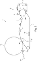
- the papermaking machine 1 of Figure 1 is a machine intended for manufacturing a tissue paper web with high bulk such as, for example, TAD paper.
- the machine may be intended for manufacturing tissue paper that has a basis weight that may be in the range of, for example, 12 g/m 2 - 40 g/m 2 and may include such grades as, for example, toilet paper or kitchen towel.
- the papermaking machine of Figure 1 comprises a forming section 2 with a first forming fabric 3 and a second forming fabric 4.
- the forming fabrics 3, 4 may be, for example, foraminous forming wires that are air and water permeable.
- Each of the forming fabrics 3, 4 is arranged to run in a loop supported by guide rolls 7.
- the forming fabrics 3, 4 will run in the direction indicated by the arrows S.
- a head box 5 is arranged to inject stock in a gap between the forming fabrics 3, 4 as is known in the art to which the invention pertains.
- the reference numeral 34 indicates a forming roll.
- the forming section is followed by a drying section 8 that comprises a through-air-drying cylinder 9 (TAD cylinder 9).
- TID cylinder 9 a through-air-drying cylinder 9
- the permeable fabric 6 is a through-air drying fabric (TAD fabric) that is arranged to run in a loop supported by guide rolls 7 in the direction of arrow S.
- a pick-up suction device 14 may be arranged within the loop of the TAD fabric 6 to assist in transferring the fibrous web W from the forming fabric 4 to the TAD fabric 6.
- the web W is then carried on the TAD fabric 6 around a part of the circumference of the through-air drying cylinder 9 (TAD cylinder 9).
- the TAD cylinder 9 is arranged in a hood 10.
- the hood 10 and the TAD cylinder may be arranged to operate such that hot air passes from the hood 10, through the fibrous web W and the TAD fabric 6 and into the TAD cylinder 9 and the air may then be evacuated from the TAD cylinder 9 in an axial direction.
- Embodiments are conceivable in which the hot air goes the other way, i.e.
- the fibrous web W is dried as it passes the TAD cylinder 9 and is then passed further, for example to a reel-up.
- the reel-up is not shown in the figures but, with reference to Figure 1 , it would normally be located to the left of the drying section 8.
- Such a reel-up could take many forms and it may be, for example, such a reel-up as is disclosed in US patent No. 5901918 .
- the arrangement of the reel-up in relation to the rest of the machine may be such that the reel-up is arranged to receive the fibrous web from the drying section 8, for example from the TAD fabric 6.
- the fibrous web may be sent from the drying section 8 in an open draw to the reel-up or supported by something, for example supported by a fabric.
- the TAD cylinder 9 is followed by a Yankee drying cylinder (not shown) and in which the fibrous web is subsequently passed to a reel-up.
- the fibrous web W Before the fibrous web W reaches the TAD cylinder 9, it passes a suction device 15 that is placed inside the loop of the permeable TAD fabric 6. At this stage, the fibrous web W may have a dryness of about 25 % or perhaps even less and the web W can easily be shaped.
- the suction device 15 may be a moulding box intended to assist in creating a three-dimensional structure into the fibrous web W.
- the suction device 15 As the fibrous web W passes the suction device 15, a suction effect from the suction device 15 pulls the fibrous web W against the TAD fabric 6. As the TAD fabric 6 has a three-dimensional pattern with knuckles, fibers in the fibrous web W will be partially sucked into the TAD fabric such that the TAD fabric creates a three-dimensional pattern in the surface of the fibrous web W, or at least into the side of the fibrous web that faces the TAD fabric. The suction device 15 plays an important role in this process.
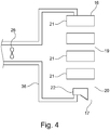
- the machine of Figure 2 has a forming section 2 with a head box 5, a first forming fabric 3 and a second forming fabric 4.
- the fabrics 3, 4 both of which are water and air permeable fabrics) run in the direction of arrows S and they are supported in their loops by guide rolls 7.
- the drying section 8 comprises a drying cylinder 11 which may be a Yankee drying cylinder 11.
- a newly formed fibrous web W travels on the lower side of the permeable fabric 4 (the fabric 4 may be a felt) to a nip N between a press roll 12 and the Yankee drying cylinder 11.
- the web W is transferred to the surface of the Yankee drying cylinder 11.
- the surface of the Yankee drying cylinder 11 is smoother than the surface of the fabric 4 which would typically be a felt. Since the surface of the Yankee drying cylinder is smoother than the surface of the fabric 4, the web W will follow the surface of the Yankee drying cylinder 11 after the nip N.
- the web W is dried and subsequently creped from the surface of the Yankee drying cylinder by a doctor 13.
- a suction device 15 is placed inside the loop of the permeable fabric 4 and the suction device 15 may serve the purpose of dewatering. It should be understood that other machine configurations are also possible and the suction device 15 may be placed inside the loop of a wire, for example in order to achieve additional dewatering of the fibrous web.
- a suction device acting on a fibrous web through a permeable fabric such as, for example, a TAD fabric, typically has a number of slots or openings through which underpressure can act.
- the underpressure vacuum
- the inventors have noted that in some applications using a suction device inside the loop of a permeable fabric, there may be disturbances in the process downstream of the suction device.
- the inventors have now identified the operation of the suction device as one source of such disturbances.
- the present invention aims at eliminating or at least reducing this problem such that disturbances of the papermaking process also can be reduced.
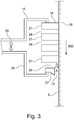
- FIG. 3 shows a suction device 15 for use in a papermaking machine 1.
- the suction device 15 is suitable for acting on a wet fibrous web W through a permeable fabric 6 that runs through a part of the papermaking machine 1.
- the permeable fabric 6 may be a TAD fabric which has a three-dimensional pattern that can be formed by, for example, longitudinal yarns extending in the machine direction and transverse yarns extending in the cross machine direction.
- the three-dimensional pattern may include knuckles and recessed portions surrounding the knuckles.
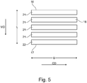
- the suction device 15 has a length L that extends from a first end 16 to a second end 17.
- the first end 16 is an upstream end when the suction device 15 is used in the papermaking machine 1 and the second end 17 is a downstream end when the suction device 15 is used in the papermaking machine 1.
- the direction from the first end 16 to the second end 17 is the machine direction MD when the suction device 15 is used in the papermaking machine 1.
- the suction device 15 further has a width B which is perpendicular to the length L of the suction device 15. The width B extends in the cross-machine direction (the CD direction) when the suction device 15 is used in the papermaking machine 1.
- the suction device 15 has a surface 18 which, during use of the suction device 15 in the papermaking machine, will be facing the permeable fabric 4, 6 and thus be a fabric-facing surface 18.
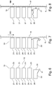
- the fabric-facing surface 18 has a first part 19 which begins at the first end 16 of the suction device 15 and extends towards the second end 17 but ends before the second end 17 of the suction device.
- the first part 19 of the fabric-facing surface 18 is formed by planar surfaces 23 (see Figure 6 ) on a plurality of solid elements 21 which planar surfaces 23 form a part of the fabric-facing surface 18.
- the planar surfaces 23 of the solid elements 21 in the first part 19 of the fabric-facing surface 18 lie in the same plane such that, during operation, they can contact a fabric 4, 6 that glides over the fabric-facing surface 18 along a straight path.
- the solid elements 21 are separated from each other along the length of the suction device 15 such that channels 24 are defined between the solid elements 21.
- the spacing between the solid elements 21 may vary from case to case but in some embodiments contemplated by the inventors, the distance that separates the solid elements 21 from each other in the machine direction may be on the order of 15 mm - 25 mm, for example 18 mm.
- the spacing between the solid elements 21 may be the same for all solid elements 21 but it may conceivably also vary.
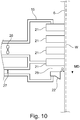
- the suction device 15 is configured to be connected to at least one source of underpressure which is symbolically indicated as a fan 26 in Figure 3 and Figure 4 .
- the at least one source of underpressure 26 may communicate with the channels 24 defined between the solid elements 21 such that, when the suction device 15 is used and the permeable fabric 6 runs over the fabric-facing surface 18, the suction device 15 can act on the permeable fabric 6 through the channels 24 and draw the permeable fabric 6 by suction effect towards the fabric-facing surface 18.
- the first part 19 of the fabric-facing surface 18 is followed by a second part 20 of the fabric-facing surface 18.
- the second part 20 of the fabric-facing surface comprises a surface 33 (see Figure 6 ) that does not lie in the same plane as the planar surfaces 23 of the solid elements belonging to the first part 19 of the fabric-facing surface 18 but is spaced from the plane in which the planar surfaces 23 of the solid elements 21 in the first part of the fabric-facing surface 18.
- the plane in which the surface 33 of the second part 20 of the fabric-facing surface 18 will normally be parallel or substantially parallel to the plane in which the planar surfaces 23 of the solid elements belonging to the first part of the fabric-facing surface 18 but the two planes are separated from each other in a direction which is normal to the two planes, i.e. perpendicular to the two planes.
- the surface 33 which does not lie in the same plane as the planar surfaces 23 in the first part of the fabric-facing surface 18 is formed on a final solid element 22 and can be seen as that end of the final solid element 22 which, during operation, will be facing the permeable fabric 6.
- Figure 3 it can be seen how the plane in which the planar surface 33 of the final solid element 22 lies is separated from the plane in which the planar surfaces 23 lie by a distance D. Therefore, when the permeable fabric 6 passes over the suction device 15 and moves past the final solid element 22 along the plane of the planar surfaces 23 of the solid elements 21 in the first part 19 of the fabric-facing surface 18, the permeable fabric 6 will not contact the final solid element 22.
- the exact value of the distance D depends on the circumstances of each individual case but in some embodiments contemplated by the inventors, the distance D may be in the range of 3 mm - 10 mm, for example 5 mm or 7 mm but other values for the distance D are also conceivable and the distance D may conceivably be larger than 10 mm.
- the final solid element 22 is separated from a preceding solid element 21 such that a final channel 25 is defined between the final solid element 22 and the preceding solid element 21.
- the final channel 25 is capable of communicating with at least one source of underpressure for the final channel 25 when the at least one source of underpressure for the final channel 25 is connected to the suction device 15 such that an underpressure can be generated in the area between the permeable fabric 4, 6 and the surface of the final solid element 22.
- the source of underpressure 26 is the same for both the final channel 25 and the preceding channels 24 but embodiments are conceivable in which this is not the case.
- the suction device 15 may have a housing 36 that holds the solid elements 21, 22 such that the solid elements 21, 22 are secured/fastened to the housing 36 or in the housing 36.
- the solid elements 21, 22 can be understood as ribs that extend in a direction substantially perpendicular to the machine direction, i.e. in the cross machine direction and that also have a certain extension in a direction perpendicular to the plane of the planar surfaces 23.
- the ribs have ends at the fabric-facing surface 18 which ends constitute the surfaces 23, 33 of the solid elements 21, 22.
- the ends of some or all solid elements 21, 22 may optionally (but not necessarily) be formed by a piece 28 of a ceramic material such that one or several of the planar surfaces 23, 33 may be formed on a ceramic material.
- at least the ends of the ribs that constitute surfaces of the solid elements 21 in the first part of the fabric-facing surface 18 are made of a ceramic material 28.
- the use of a ceramic material means that friction can be kept low and the resistance to wear is improved.
- the final channel 25 formed between the ribs that constitute the final solid element 22 and the solid element 21 immediately preceding the final solid element 22 has a smaller cross-sectional area than the preceding channels 24.
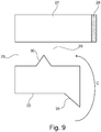
- the final channel 25 formed between the ribs that constitute the final solid element 22 and the solid element 21 immediately preceding the final solid element 22 may be provided with a flow restrictor 30, for example a flow restrictor which, in cross section, is "pyramid-shaped" as shown in Figure 9 but other shapes are also conceivable, for example rectangular shapes or flow restrictors 30 which, in cross section, have a curved shape.
- the suction device 15 is configured such that the channels 24 defined between the solid elements associated with the first part 19 of the fabric-facing surface 18 can be connected to and communicate with at least one first source of underpressure 26 and that the final channel 25 can be connected to and communicate with at least one second source of underpressure 27 which is separate from the at least one first source or underpressure 26.
- the first and second source of underpressure 26, 27 are symbolically shown as fans (and they may conceivably be or comprise fans).
- a common source of underpressure may be used while the air flow through the final channel 25 is regulated by means of a control valve (not shown in the figures).
- the suction device 15 may be formed as a single unit.
- the inventive form of the suction device has the effect that fines and fibers that get blind the final channel are dewatered by the air flow and that, instead of falling off in large lumps, they fall off the suction device in the shape of individual fines or fibers that are substantially dry and that are individually too small to cause any noticeable disturbances.
- the final solid element 22 may have an extension 35 that is shaped as a triangle pointing in the machine direction.
- This extension 35 is optional and need not be present.
- the extension 35 may serve to extend the length of the gap A. It may also serve to guide away condensated water droplets.
- the extension 35 (if present) may also be used simply for the purpose of securing the final element 22 to the housing 36.
- the final channel 25 has a part 29 with a smaller cross-sectional area than the preceding channels 24, for example if it has a flow restrictor 30, this entails the advantage that it will be easier to achieve the effect that the final channel 25 gets blinded such that the required air flow is reduced.
- the suction device 15 is vertically oriented or substantially vertically oriented.
- the inventive suction device need not necessarily take the form of a moulding box in a TAD machine but could also be used in other places in a paper making machine, for example in such configurations in which the endless permeable fabric is a forming fabric 4 in the forming section.
- the fabric-facing surface 18 of the suction device 15 need not be vertically arranged but could have an orientation that is horizontal or deviates from a horizontal orientation by no more than 15°.
- the fabric-facing surface 18 of the suction device 15 is then facing downwards such that the permeable fabric 4 passes below the suction device 15.
- FIG. 2 An example of such a configuration is shown in Figure 2 where a suction device could be employed for additional water removal in the forming section but it should be understood that the configuration of Figure 2 is only an example since suction devices may be placed in a horizontal or substantially horizontal position inside the loop of practically any permeable fabric in a paper making machine. Of course, it may also be placed in a vertical position for a number of reasons or in such a position that its orientation is somewhere between a vertical orientation and a horizontal orientation.
- the invention may thus be understood also in terms of a papermaking machine that makes use of the inventive suction device.
- the machine according to the invention comprises a forming section 2 and a drying section 8 and the machine is arranged to cause a newly formed fibrous web W to move along a path of travel that extends in the machine direction from the forming section 2 to and into the drying section 8.
- the papermaking machine 1 comprises an endless permeable fabric 4, 6 and a plurality of guide rolls 7 around which the endless permeable fabric 4, 6 runs in a loop and the endless permeable fabric 4, 6 is arranged to carry the fibrous web W at least a part of the path of travel of the web W and the papermaking machine 1 comprises a suction device 15 according to the invention and the suction device 15 is arranged inside the loop of the endless permeable fabric 4, 6 with the fabric-facing surface 18 facing the endless permeable fabric.
- the drying section comprises a through-air-drying cylinder 9 and the endless permeable fabric 6 is a through-air-drying fabric which is arranged to wrap a part of the through-air-drying cylinder 9 and the suction device 15 is placed within the loop of the permeable fabric 6 such that it can act on the permeable fabric 6 and on a fibrous web W carried by the permeable fabric 6 and separated from the suction device 15 by the permeable fabric 6.
- the suction device 15 is then placed upstream of the through-air-drying cylinder 9 such that it acts on the permeable fabric 6 before the permeable fabric 6 reaches the through-air-drying cylinder 9, and the fabric-facing surface 18 of the suction device 15 has an orientation that is more vertical than horizontal.
- the surface 33 of the final solid element 22 may be planar just as the planar surfaces 23 of the solid elements belonging to the first part 19 of the fabric-facing surface 18 but it could also have another shape, for example a round shape. Since the final solid element 22 will not contact the permeable fabric 4, 6, the final solid element 22 and the surface 33 may very well be formed in a material such as High Density Polyethylene (HDPE) which is less expensive and which can easily be machined.
- HDPE High Density Polyethylene
- the inventive suction device is in particular useful as a moulding box in a TAD machine (a Through Air Drying machine) for making through-dried tissue paper such as tissue paper having a basis weight in the range of, for example, 10 g/m 2 - 30 g/m 2 but it could also be used as, for example, a transfer suction box in a tissue paper making machine or as a dewatering element in, for example, the forming section of a tissue paper making machine such as a TAD machine. While the inventive suction device may be particularly useful in TAD machines, it may also be used in other tissue machines than TAD machines, for example as a transfer suction box or dewatering element.
- TAD machine a Through Air Drying machine
- inventive suction device is in particular intended for tissue machines (e.g. TAD machines), it may also be applied in machines for heavier grades than tissue.
- the invention may be defined in terms of a method of operating the inventive papermaking machine.
- the newly formed fibrous web would be caused to travel along a path of travel extending in the machine direction from the forming section and to the drying section and thereby pass the inventive suction device while at least one source of underpressure was connected to the inventive suction device and the source of underpressure is active (operated) to produce underpressure such that a suction effect through the suction device is generated and underpressure acts through the permeable fabric on the fibrous web as the fibrous web passes the inventive suction device.
Landscapes
- Paper (AREA)
Claims (11)
- Un dispositif d'aspiration (15) destiné à être utilisé dans une machine à papier (1) et adapté pour agir sur une bande fibreuse humide (W) à travers un tissu perméable (4, 6) qui traverse une partie de la machine à papier (1), le dispositif d'aspiration (15) ayant une longueur (L) qui s'étend d'une première extrémité (16) àune deuxième extrémité (17), laquelle première extrémité (16) est une extrémité amont lorsque le dispositif d'aspiration (15) est utilisé dans la machine à papier (1) et laquelle deuxième extrémité (17) est une extrémité aval lorsque le dispositif d'aspiration (15) est utilisé dans la machine à papier (1), la direction allant de la première extrémité (16) à la deuxième extrémité (17) étant la direction de la machine (MD) lorsque le dispositif d'aspiration (15) est utilisé dans la machine à papier (1), le dispositif d'aspiration (15) ayant en outre une largeur (B) qui est perpendiculaire à la longueur (L) du dispositif d'aspiration (15) et s'étend dans la direction transversale de la machine lorsque le dispositif d'aspiration (15) est utilisé dans la machine à papier (1), le dispositif d'aspiration (15) ayant en outre un surface (18) qui, pendant l'utilisation du dispositif d'aspiration (15) dans la machine à papier, sera tournée vers le tissu perméable (4, 6) et sera donc une surface (18) tournée vers le tissu, la surface (18) tournée vers le tissu ayant une première partie (19) qui commence à la première extrémité (16) du dispositif d'aspiration (15) et qui s'étend vers la deuxième extrémité (17) mais se termine avant la deuxième extrémité (17) du dispositif d'aspiration, la première partie (19) de la surface (18) tournée vers le tissu étant formée par une pluralité de surfaces planes (23) lesquelles surfaces planes (23) constituent des surfaces d'extrémité d'une pluralité d'éléments solides (21), les surfaces planes (23) des éléments solides (21) dans la première partie (19) de la surface (18) tournée vers le tissu se trouvant dans le même plan de sorte que, pendant le fonctionnement, elles peuvent entrer en contact avec un tissu (4, 6) glissant sur la surface (18) tournée vers le tissu selon un cheminement droit, les éléments solides (21) étant séparés les uns des autres sur la longueur du dispositif d'aspiration (15) de sorte que des canaux (24) soient définis entre les éléments solides (21), le dispositif d'aspiration (15) étant conçu pour être relié à au moins une source de dépression (26, 27) de telle sorte que ladite au moins une source de dépression (26, 27) est en communication avec les canaux (24) définis entre les éléments solides (21) de telle sorte que, lorsque le dispositif d'aspiration (15) est utilisé et que le tissu perméable (4, 6) passe sur la surface (18) tournée vers le tissu, le dispositif d'aspiration (15) est apte à agir sur le tissu perméable (4, 6) à travers les canaux (24) et tirer le tissu perméable (4, 6) en exerçant un effet d'aspiration vers la surface (18) tournée vers le tissu, caractérisé en ce que la première partie (19) de la surface (18) tournée vers le tissu est suivie d'une deuxième partie (20) de la surface (18) tournée vers le tissu, laquelle deuxième partie (20) de la surface (18) tournée vers le tissu est une surface (33) formée en tant qu'une surface d'extrémité d'un élément solide final (22) et laquelle surface d'extrémité (33) de l'élément solide final (22) ne s'étend pas dans le même plan que les surfaces planes (23) des éléments solides (21) appartenant à la première partie (19) de la surface (18) tournée vers le tissu mais est espacée du plan dans lequel se trouvent les surfaces planes (23) des éléments solides (2) appartenant à la première partie (19) de la surface (18) tournée vers le tissu, de telle sorte que, lorsque le tissu perméable (4, 6) passe au-dessus du dispositif d'aspiration (15) et qu'il se déplace au-delà de l'élément solide final (22) le long du plan des surfaces planes des éléments solides (21) appartenant à la première partie (19) de la surface (18) tournée vers le tissu, le tissu perméable (4, 6) ne vient pas en contact avec l'élément solide final (22), l'élément solide final (22) étant séparé d'un élément solide précédent (21) de telle sorte qu'un canal final (25) est défini entre l'élément solide final (22) et l'élément solide précédent (21) et le canal final (25) étant apte à communiquer avec au moins une source de dépression (26, 27) pour le canal final (25) lorsque ladite au moins une source de dépression (26, 27) pour le canal final (25) est reliée au dispositif d'aspiration (15) de telle sorte qu'une dépression peut être générée dans la zone située entre le tissu perméable (4, 6) et le surface de l'élément solide final (22).
- Un dispositif d'aspiration (15) selon la revendication 1, dans lequel les éléments solides (21, 22) sont des nervures qui s'étendent dans une direction perpendiculaire à la direction de la machine et dans la direction transversale de la machine, c'est-à-dire perpendiculaire à la dimension longitudinale et transversale du dispositif d'aspiration, les nervures ayant des extrémités au niveau de la surface (18) tournée vers le tissu, lesquelles extrémités constituent les surfaces (23, 33) des éléments solides (21, 22).
- Un dispositif d'aspiration selon la revendication 2, dans lequel au moins les extrémités des nervures qui constituent des surfaces des éléments solides (21) dans la première partie de la surface (18) tournée vers le tissu sont faites en un matériau céramique (28).
- Un dispositif d'aspiration selon la revendication 2 ou la revendication 3, dans lequel au moins une partie (29) du canal final (25) formée entre les nervures qui constituent l'élément solide final (22) et l'élément solide (21) précédant immédiatement l'élément solide final (22) a une surface en section transversale qui est plus petite que les canaux précédents (24).
- Un dispositif d'aspiration (15) selon la revendication 2 ou la revendication 3, caractérisé en ce que le canal final (25) formé entre les nervures qui constituent l'élément solide final (22) et l'élément solide (21) précédant immédiatement l'élément solide final (22) est muni d'un réducteur d'écoulement (30).
- Un dispositif d'aspiration selon l'une quelconque des revendications 1 à 5, dans lequel le dispositif d'aspiration (15) est configuré de telle sorte que les canaux (24) définis entre les éléments solides de la première partie (19) de la surface (18) tournée vers le tissu sont aptes à être reliés à au moins une première source de dépression (26) et à communiquer avec celle-ci, et que le canal final (25) est apte à être relié à au moins une deuxième source de dépression (27), et à communiquer avec celle-ci, qui est séparée de ladite au moins une première source de dépression (26).
- Un dispositif d'aspiration selon la revendication 6, dans lequel le dispositif d'aspiration (15) est sous la forme d'une unité unique.
- Un dispositif d'aspiration selon l'une quelconque des revendications 1 à 5, dans lequel l'aspiration d'aspiration (15) est configuré de telle sorte que les deux canaux (24) définis entre les éléments solides (21) de la première partie (19) de la surface (18) tournée vers le tissu et le canal final (25) sont tous aptes à être reliés à au moins une source commune de dépression (26) et à communiquer avec celle-ci.
- Une machine à papier comprenant une section de formage (2) et une section de séchage (8) et la machine étant agencée pour amener une bande fibreuse (W) nouvellement formée à se déplacer le long d'un cheminement de déplacement qui s'étend dans la direction de la machine depuis la section de formage (2) vers et dans la section de séchage (8), la machine à papier (1) comprenant un tissu perméable sans fin (4, 6) et une pluralité de cylindres de guidage (7) autour desquels le tissu perméable sans fin (4, 6) s'étend selon une boucle, le tissu perméable sans fin (4, 6) étant agencé pour supporter la bande fibreuse (W) sur au moins une partie du trajet de déplacement de la bande (W), et la machine à papier (1) comprenant un dispositif d'aspiration (15) selon l'une quelconque des revendications 1 à 8, et le dispositif d'aspiration (15) étant agencé dans la boucle du tissu perméable sans fin (4, 6) avec la surface (18) tournée vers le tissu faisant face au tissu perméable sans fin.
- Une machine à papier selon la revendication 9, dans laquelle la section de séchage comprend un cylindre (9) de séchage par air traversant et le tissu perméable sans fin (6) est un tissu de séchage par air traversant qui est agencé de façon à envelopper une partie du cylindre (9) de séchage par air traversant, et dans laquelle le dispositif d'aspiration (15) est placé dans la boucle du tissu perméable (6) de telle sorte qu'il soit apte à agir sur le tissu perméable (6) et sur une bande fibreuse (W) portée par le tissu perméable (6) et séparée du dispositif d'aspiration (15) par le tissu perméable (6), le dispositif d'aspiration (15) étant placé en amont du cylindre (9) de séchage par air traversant de telle sorte qu'il agisse sur le tissu perméable (6) avant que le tissu perméable (6) n'atteigne le cylindre (9) de séchage par air traversant, la surface (18) du dispositif d'aspiration (15) tournée vers le tissu ayant une orientation qui est plus verticale que horizontale.
- Une machine à papier selon la revendication 9, dans laquelle le tissu perméable sans fin (4) est un tissu de formage (4) dans la section de formage et la surface (18) du dispositif d'aspiration (15) tournée vers le tissu a une orientation qui est horizontale ou qui ne s'écarte pas d'une orientation horizontale de plus de 15°, et la surface (18) du dispositif d'aspiration (15) tournée vers le tissu est tournée vers le bas de telle sorte que le tissu perméable (4) passe sous le dispositif d'aspiration (15).
Applications Claiming Priority (1)
| Application Number | Priority Date | Filing Date | Title |
|---|---|---|---|
| PCT/SE2015/051208 WO2017082788A1 (fr) | 2015-11-12 | 2015-11-12 | Dispositif d'aspiration destiné à être utilisé dans une machine à papier, et machine à papier utilisant un dispositif d'aspiration |
Publications (3)
| Publication Number | Publication Date |
|---|---|
| EP3374565A1 EP3374565A1 (fr) | 2018-09-19 |
| EP3374565A4 EP3374565A4 (fr) | 2019-05-01 |
| EP3374565B1 true EP3374565B1 (fr) | 2020-01-15 |
Family
ID=58695840
Family Applications (1)
| Application Number | Title | Priority Date | Filing Date |
|---|---|---|---|
| EP15908400.3A Active EP3374565B1 (fr) | 2015-11-12 | 2015-11-12 | Dispositif d'aspiration destiné à être utilisé dans une machine à papier, et machine à papier utilisant un dispositif d'aspiration |
Country Status (6)
| Country | Link |
|---|---|
| US (2) | US10132034B2 (fr) |
| EP (1) | EP3374565B1 (fr) |
| CN (1) | CN108350657B (fr) |
| CA (1) | CA2997412C (fr) |
| MX (1) | MX2018002942A (fr) |
| WO (1) | WO2017082788A1 (fr) |
Families Citing this family (4)
| Publication number | Priority date | Publication date | Assignee | Title |
|---|---|---|---|---|
| CN108350657B (zh) * | 2015-11-12 | 2019-11-08 | 维美德股份公司 | 用在造纸机中的抽吸装置以及使用抽吸装置的造纸机 |
| EP3378989B1 (fr) * | 2017-03-20 | 2019-10-09 | Valmet Technologies Oy | Agencement et procédé pour surveiller un cylindre yankee |
| DE102017127932A1 (de) * | 2017-11-27 | 2019-05-29 | Voith Patent Gmbh | Verfahren |
| WO2020106193A1 (fr) | 2018-11-19 | 2020-05-28 | Valmet Aktiebolag | Section de séchage d'une machine à papier comprenant au moins un cylindre de séchage à l'air traversant |
Family Cites Families (12)
| Publication number | Priority date | Publication date | Assignee | Title |
|---|---|---|---|---|
| US3928125A (en) * | 1972-12-18 | 1975-12-23 | Feldmuehle Anlagen Prod | Water extraction apparatus for papermaking machine |
| CN85104451A (zh) * | 1985-06-11 | 1986-12-10 | 美商贝洛特公司 | 正压锁紧案板刀口 |
| US4781795A (en) * | 1986-04-08 | 1988-11-01 | Ray R. Miller | Heated drum having high thermal flux and belt press using same |
| GB9321401D0 (en) * | 1993-10-16 | 1993-12-08 | Beloit Walmsley Ltd | A forming apparatus for forming a web from stock |
| US5718806A (en) * | 1996-09-03 | 1998-02-17 | The Procter & Gamble Company | Vacuum apparatus having flow management device for controlling the rate of application of vacuum pressure in a through air drying papermaking process |
| TW527482B (en) * | 1997-10-31 | 2003-04-11 | Kimberly Clark Co | Air press for dewatering wet web |
| US6306257B1 (en) * | 1998-06-17 | 2001-10-23 | Kimberly-Clark Worldwide, Inc. | Air press for dewatering a wet web |
| SE529130C2 (sv) * | 2004-05-26 | 2007-05-08 | Metso Paper Karlstad Ab | Pappersmaskin för framställning av mjukpapper, metod för framställning av mjukpapper samt mjukpapper |
| GB2418929A (en) * | 2004-10-05 | 2006-04-12 | Ian G Lang | Producing paper product |
| FI118211B (fi) * | 2006-05-19 | 2007-08-31 | Metso Paper Inc | Staattinen vedenpoistoelin rainanmuodostuskonetta varten sekä menetelmä rainanmuodostuskonetta varten olevan staattisen vedenpoistoelimen pinnoittamiseksi |
| US8163136B2 (en) * | 2010-12-16 | 2012-04-24 | FC Papel LLC | Energy saving papermaking forming apparatus system, and method for lowering consistency of fiber suspension |
| CN108350657B (zh) * | 2015-11-12 | 2019-11-08 | 维美德股份公司 | 用在造纸机中的抽吸装置以及使用抽吸装置的造纸机 |
-
2015
- 2015-11-12 CN CN201580084159.9A patent/CN108350657B/zh active Active
- 2015-11-12 CA CA2997412A patent/CA2997412C/fr active Active
- 2015-11-12 EP EP15908400.3A patent/EP3374565B1/fr active Active
- 2015-11-12 US US15/763,401 patent/US10132034B2/en active Active
- 2015-11-12 WO PCT/SE2015/051208 patent/WO2017082788A1/fr not_active Ceased
- 2015-11-12 MX MX2018002942A patent/MX2018002942A/es unknown
-
2018
- 2018-11-13 US US16/189,547 patent/US20190078260A1/en not_active Abandoned
Non-Patent Citations (1)
| Title |
|---|
| None * |
Also Published As
| Publication number | Publication date |
|---|---|
| EP3374565A1 (fr) | 2018-09-19 |
| CA2997412A1 (fr) | 2017-05-18 |
| US20190078260A1 (en) | 2019-03-14 |
| CA2997412C (fr) | 2022-05-31 |
| MX2018002942A (es) | 2018-06-18 |
| US20180298555A1 (en) | 2018-10-18 |
| EP3374565A4 (fr) | 2019-05-01 |
| WO2017082788A1 (fr) | 2017-05-18 |
| US10132034B2 (en) | 2018-11-20 |
| CN108350657A (zh) | 2018-07-31 |
| CN108350657B (zh) | 2019-11-08 |
Similar Documents
| Publication | Publication Date | Title |
|---|---|---|
| US7959764B2 (en) | Forming fabrics for fiber webs | |
| US20190078260A1 (en) | Suction device for use in a papermaking machine and a papermaking machine using a suction device | |
| KR20020068514A (ko) | 트윈 와이어 성형 섹션을 갖는 단순화된 통-기 제지기계 | |
| JPH0742680B2 (ja) | ウェブを乾燥する装置及び方法 | |
| EP3092191B1 (fr) | Enrouleuse pour recevoir et enrouler sous la forme d'un rouleau une bande de papier qui arrive à partir d'un cylindre de séchage dans une machine à papier, et machine à papier utilisant une enrouleuse | |
| US5147508A (en) | Suction box covers for cleaning papermaking machine felts | |
| KR101535315B1 (ko) | 제지 직물과 이를 제조하기 위한 장치 및 방법 | |
| WO2002068753A2 (fr) | Systeme et procede de support de bande lors du transfert d'une bande de papier entre des elements d'une machine a papier | |
| CN103781966B (zh) | 用于制造纤维幅的机器的压榨部 | |
| EP0738344B1 (fr) | Sechage de feuille continue | |
| CN110770395B (zh) | 造纸机和在造纸机中切割纤维幅材的方法 | |
| CN110612370B (zh) | 用于制造纤维料幅的制造装置和方法 | |
| US10240292B2 (en) | Through-air drying apparatus and methods of manufacture | |
| JP4350712B2 (ja) | ウェブ成形機のプレス部 | |
| US7721464B2 (en) | System and process for throughdrying tissue products | |
| US3555700A (en) | Roll for papermaking machinery | |
| US12146265B2 (en) | Dewatering box cover | |
| US7686922B2 (en) | Process and device for dewatering a fiber web | |
| US7976681B2 (en) | Apparatus to produce a fibrous web | |
| CA3130643A1 (fr) | Couvercle de boitier de deshydratation | |
| WO2008152196A1 (fr) | Procédé et appareil de fabrication du papier | |
| FI120293B (fi) | Menetelmä ja laite reunanauhan kulun ohjaamiseksi | |
| WO2009156593A1 (fr) | Machine à sécher la pâte à papier et procédé de séchage de bande de pâte à papier |
Legal Events
| Date | Code | Title | Description |
|---|---|---|---|
| STAA | Information on the status of an ep patent application or granted ep patent |
Free format text: STATUS: THE INTERNATIONAL PUBLICATION HAS BEEN MADE |
|
| PUAI | Public reference made under article 153(3) epc to a published international application that has entered the european phase |
Free format text: ORIGINAL CODE: 0009012 |
|
| STAA | Information on the status of an ep patent application or granted ep patent |
Free format text: STATUS: REQUEST FOR EXAMINATION WAS MADE |
|
| 17P | Request for examination filed |
Effective date: 20180522 |
|
| AK | Designated contracting states |
Kind code of ref document: A1 Designated state(s): AL AT BE BG CH CY CZ DE DK EE ES FI FR GB GR HR HU IE IS IT LI LT LU LV MC MK MT NL NO PL PT RO RS SE SI SK SM TR |
|
| AX | Request for extension of the european patent |
Extension state: BA ME |
|
| DAV | Request for validation of the european patent (deleted) | ||
| DAX | Request for extension of the european patent (deleted) | ||
| A4 | Supplementary search report drawn up and despatched |
Effective date: 20190402 |
|
| RIC1 | Information provided on ipc code assigned before grant |
Ipc: D21F 11/14 20060101ALI20190327BHEP Ipc: D21F 9/00 20060101ALI20190327BHEP Ipc: D21F 5/18 20060101ALI20190327BHEP Ipc: D21F 11/00 20060101ALI20190327BHEP Ipc: D21F 1/52 20060101AFI20190327BHEP |
|
| RIC1 | Information provided on ipc code assigned before grant |
Ipc: D21F 11/14 20060101ALI20190805BHEP Ipc: D21F 11/00 20060101ALI20190805BHEP Ipc: D21F 1/52 20060101AFI20190805BHEP |
|
| GRAP | Despatch of communication of intention to grant a patent |
Free format text: ORIGINAL CODE: EPIDOSNIGR1 |
|
| STAA | Information on the status of an ep patent application or granted ep patent |
Free format text: STATUS: GRANT OF PATENT IS INTENDED |
|
| INTG | Intention to grant announced |
Effective date: 20190926 |
|
| GRAS | Grant fee paid |
Free format text: ORIGINAL CODE: EPIDOSNIGR3 |
|
| GRAA | (expected) grant |
Free format text: ORIGINAL CODE: 0009210 |
|
| STAA | Information on the status of an ep patent application or granted ep patent |
Free format text: STATUS: THE PATENT HAS BEEN GRANTED |
|
| AK | Designated contracting states |
Kind code of ref document: B1 Designated state(s): AL AT BE BG CH CY CZ DE DK EE ES FI FR GB GR HR HU IE IS IT LI LT LU LV MC MK MT NL NO PL PT RO RS SE SI SK SM TR |
|
| REG | Reference to a national code |
Ref country code: CH Ref legal event code: EP Ref country code: GB Ref legal event code: FG4D |
|
| REG | Reference to a national code |
Ref country code: IE Ref legal event code: FG4D |
|
| REG | Reference to a national code |
Ref country code: DE Ref legal event code: R096 Ref document number: 602015045858 Country of ref document: DE |
|
| REG | Reference to a national code |
Ref country code: AT Ref legal event code: REF Ref document number: 1225246 Country of ref document: AT Kind code of ref document: T Effective date: 20200215 |
|
| REG | Reference to a national code |
Ref country code: NL Ref legal event code: MP Effective date: 20200115 |
|
| REG | Reference to a national code |
Ref country code: LT Ref legal event code: MG4D |
|
| PG25 | Lapsed in a contracting state [announced via postgrant information from national office to epo] |
Ref country code: PT Free format text: LAPSE BECAUSE OF FAILURE TO SUBMIT A TRANSLATION OF THE DESCRIPTION OR TO PAY THE FEE WITHIN THE PRESCRIBED TIME-LIMIT Effective date: 20200607 Ref country code: NO Free format text: LAPSE BECAUSE OF FAILURE TO SUBMIT A TRANSLATION OF THE DESCRIPTION OR TO PAY THE FEE WITHIN THE PRESCRIBED TIME-LIMIT Effective date: 20200415 Ref country code: FI Free format text: LAPSE BECAUSE OF FAILURE TO SUBMIT A TRANSLATION OF THE DESCRIPTION OR TO PAY THE FEE WITHIN THE PRESCRIBED TIME-LIMIT Effective date: 20200115 Ref country code: RS Free format text: LAPSE BECAUSE OF FAILURE TO SUBMIT A TRANSLATION OF THE DESCRIPTION OR TO PAY THE FEE WITHIN THE PRESCRIBED TIME-LIMIT Effective date: 20200115 Ref country code: NL Free format text: LAPSE BECAUSE OF FAILURE TO SUBMIT A TRANSLATION OF THE DESCRIPTION OR TO PAY THE FEE WITHIN THE PRESCRIBED TIME-LIMIT Effective date: 20200115 |
|
| PG25 | Lapsed in a contracting state [announced via postgrant information from national office to epo] |
Ref country code: BG Free format text: LAPSE BECAUSE OF FAILURE TO SUBMIT A TRANSLATION OF THE DESCRIPTION OR TO PAY THE FEE WITHIN THE PRESCRIBED TIME-LIMIT Effective date: 20200415 Ref country code: IS Free format text: LAPSE BECAUSE OF FAILURE TO SUBMIT A TRANSLATION OF THE DESCRIPTION OR TO PAY THE FEE WITHIN THE PRESCRIBED TIME-LIMIT Effective date: 20200515 Ref country code: LV Free format text: LAPSE BECAUSE OF FAILURE TO SUBMIT A TRANSLATION OF THE DESCRIPTION OR TO PAY THE FEE WITHIN THE PRESCRIBED TIME-LIMIT Effective date: 20200115 Ref country code: SE Free format text: LAPSE BECAUSE OF FAILURE TO SUBMIT A TRANSLATION OF THE DESCRIPTION OR TO PAY THE FEE WITHIN THE PRESCRIBED TIME-LIMIT Effective date: 20200115 Ref country code: GR Free format text: LAPSE BECAUSE OF FAILURE TO SUBMIT A TRANSLATION OF THE DESCRIPTION OR TO PAY THE FEE WITHIN THE PRESCRIBED TIME-LIMIT Effective date: 20200416 Ref country code: HR Free format text: LAPSE BECAUSE OF FAILURE TO SUBMIT A TRANSLATION OF THE DESCRIPTION OR TO PAY THE FEE WITHIN THE PRESCRIBED TIME-LIMIT Effective date: 20200115 |
|
| REG | Reference to a national code |
Ref country code: DE Ref legal event code: R097 Ref document number: 602015045858 Country of ref document: DE |
|
| PG25 | Lapsed in a contracting state [announced via postgrant information from national office to epo] |
Ref country code: SK Free format text: LAPSE BECAUSE OF FAILURE TO SUBMIT A TRANSLATION OF THE DESCRIPTION OR TO PAY THE FEE WITHIN THE PRESCRIBED TIME-LIMIT Effective date: 20200115 Ref country code: LT Free format text: LAPSE BECAUSE OF FAILURE TO SUBMIT A TRANSLATION OF THE DESCRIPTION OR TO PAY THE FEE WITHIN THE PRESCRIBED TIME-LIMIT Effective date: 20200115 Ref country code: EE Free format text: LAPSE BECAUSE OF FAILURE TO SUBMIT A TRANSLATION OF THE DESCRIPTION OR TO PAY THE FEE WITHIN THE PRESCRIBED TIME-LIMIT Effective date: 20200115 Ref country code: DK Free format text: LAPSE BECAUSE OF FAILURE TO SUBMIT A TRANSLATION OF THE DESCRIPTION OR TO PAY THE FEE WITHIN THE PRESCRIBED TIME-LIMIT Effective date: 20200115 Ref country code: SM Free format text: LAPSE BECAUSE OF FAILURE TO SUBMIT A TRANSLATION OF THE DESCRIPTION OR TO PAY THE FEE WITHIN THE PRESCRIBED TIME-LIMIT Effective date: 20200115 Ref country code: ES Free format text: LAPSE BECAUSE OF FAILURE TO SUBMIT A TRANSLATION OF THE DESCRIPTION OR TO PAY THE FEE WITHIN THE PRESCRIBED TIME-LIMIT Effective date: 20200115 Ref country code: RO Free format text: LAPSE BECAUSE OF FAILURE TO SUBMIT A TRANSLATION OF THE DESCRIPTION OR TO PAY THE FEE WITHIN THE PRESCRIBED TIME-LIMIT Effective date: 20200115 Ref country code: CZ Free format text: LAPSE BECAUSE OF FAILURE TO SUBMIT A TRANSLATION OF THE DESCRIPTION OR TO PAY THE FEE WITHIN THE PRESCRIBED TIME-LIMIT Effective date: 20200115 |
|
| REG | Reference to a national code |
Ref country code: AT Ref legal event code: UEP Ref document number: 1225246 Country of ref document: AT Kind code of ref document: T Effective date: 20200115 |
|
| PLBE | No opposition filed within time limit |
Free format text: ORIGINAL CODE: 0009261 |
|
| STAA | Information on the status of an ep patent application or granted ep patent |
Free format text: STATUS: NO OPPOSITION FILED WITHIN TIME LIMIT |
|
| 26N | No opposition filed |
Effective date: 20201016 |
|
| PG25 | Lapsed in a contracting state [announced via postgrant information from national office to epo] |
Ref country code: PL Free format text: LAPSE BECAUSE OF FAILURE TO SUBMIT A TRANSLATION OF THE DESCRIPTION OR TO PAY THE FEE WITHIN THE PRESCRIBED TIME-LIMIT Effective date: 20200115 Ref country code: SI Free format text: LAPSE BECAUSE OF FAILURE TO SUBMIT A TRANSLATION OF THE DESCRIPTION OR TO PAY THE FEE WITHIN THE PRESCRIBED TIME-LIMIT Effective date: 20200115 |
|
| PG25 | Lapsed in a contracting state [announced via postgrant information from national office to epo] |
Ref country code: MC Free format text: LAPSE BECAUSE OF FAILURE TO SUBMIT A TRANSLATION OF THE DESCRIPTION OR TO PAY THE FEE WITHIN THE PRESCRIBED TIME-LIMIT Effective date: 20200115 |
|
| REG | Reference to a national code |
Ref country code: CH Ref legal event code: PL |
|
| GBPC | Gb: european patent ceased through non-payment of renewal fee |
Effective date: 20201112 |
|
| PG25 | Lapsed in a contracting state [announced via postgrant information from national office to epo] |
Ref country code: LU Free format text: LAPSE BECAUSE OF NON-PAYMENT OF DUE FEES Effective date: 20201112 |
|
| REG | Reference to a national code |
Ref country code: BE Ref legal event code: MM Effective date: 20201130 |
|
| PG25 | Lapsed in a contracting state [announced via postgrant information from national office to epo] |
Ref country code: CH Free format text: LAPSE BECAUSE OF NON-PAYMENT OF DUE FEES Effective date: 20201130 Ref country code: LI Free format text: LAPSE BECAUSE OF NON-PAYMENT OF DUE FEES Effective date: 20201130 |
|
| PG25 | Lapsed in a contracting state [announced via postgrant information from national office to epo] |
Ref country code: FR Free format text: LAPSE BECAUSE OF NON-PAYMENT OF DUE FEES Effective date: 20201130 Ref country code: IE Free format text: LAPSE BECAUSE OF NON-PAYMENT OF DUE FEES Effective date: 20201112 |
|
| PG25 | Lapsed in a contracting state [announced via postgrant information from national office to epo] |
Ref country code: GB Free format text: LAPSE BECAUSE OF NON-PAYMENT OF DUE FEES Effective date: 20201112 |
|
| PG25 | Lapsed in a contracting state [announced via postgrant information from national office to epo] |
Ref country code: TR Free format text: LAPSE BECAUSE OF FAILURE TO SUBMIT A TRANSLATION OF THE DESCRIPTION OR TO PAY THE FEE WITHIN THE PRESCRIBED TIME-LIMIT Effective date: 20200115 Ref country code: MT Free format text: LAPSE BECAUSE OF FAILURE TO SUBMIT A TRANSLATION OF THE DESCRIPTION OR TO PAY THE FEE WITHIN THE PRESCRIBED TIME-LIMIT Effective date: 20200115 Ref country code: CY Free format text: LAPSE BECAUSE OF FAILURE TO SUBMIT A TRANSLATION OF THE DESCRIPTION OR TO PAY THE FEE WITHIN THE PRESCRIBED TIME-LIMIT Effective date: 20200115 |
|
| PG25 | Lapsed in a contracting state [announced via postgrant information from national office to epo] |
Ref country code: MK Free format text: LAPSE BECAUSE OF FAILURE TO SUBMIT A TRANSLATION OF THE DESCRIPTION OR TO PAY THE FEE WITHIN THE PRESCRIBED TIME-LIMIT Effective date: 20200115 Ref country code: AL Free format text: LAPSE BECAUSE OF FAILURE TO SUBMIT A TRANSLATION OF THE DESCRIPTION OR TO PAY THE FEE WITHIN THE PRESCRIBED TIME-LIMIT Effective date: 20200115 |
|
| PG25 | Lapsed in a contracting state [announced via postgrant information from national office to epo] |
Ref country code: BE Free format text: LAPSE BECAUSE OF NON-PAYMENT OF DUE FEES Effective date: 20201130 |
|
| P01 | Opt-out of the competence of the unified patent court (upc) registered |
Effective date: 20230513 |
|
| PGFP | Annual fee paid to national office [announced via postgrant information from national office to epo] |
Ref country code: DE Payment date: 20251118 Year of fee payment: 11 |
|
| PGFP | Annual fee paid to national office [announced via postgrant information from national office to epo] |
Ref country code: AT Payment date: 20251118 Year of fee payment: 11 |
|
| PGFP | Annual fee paid to national office [announced via postgrant information from national office to epo] |
Ref country code: IT Payment date: 20251121 Year of fee payment: 11 |