EP3374647B1 - Element zur positionierung einer komponente im raum - Google Patents
Element zur positionierung einer komponente im raum Download PDFInfo
- Publication number
- EP3374647B1 EP3374647B1 EP16809969.5A EP16809969A EP3374647B1 EP 3374647 B1 EP3374647 B1 EP 3374647B1 EP 16809969 A EP16809969 A EP 16809969A EP 3374647 B1 EP3374647 B1 EP 3374647B1
- Authority
- EP
- European Patent Office
- Prior art keywords
- bolt
- hollow body
- positioning element
- washer
- nut
- Prior art date
- Legal status (The legal status is an assumption and is not a legal conclusion. Google has not performed a legal analysis and makes no representation as to the accuracy of the status listed.)
- Active
Links
Images
Classifications
-
- F—MECHANICAL ENGINEERING; LIGHTING; HEATING; WEAPONS; BLASTING
- F16—ENGINEERING ELEMENTS AND UNITS; GENERAL MEASURES FOR PRODUCING AND MAINTAINING EFFECTIVE FUNCTIONING OF MACHINES OR INSTALLATIONS; THERMAL INSULATION IN GENERAL
- F16B—DEVICES FOR FASTENING OR SECURING CONSTRUCTIONAL ELEMENTS OR MACHINE PARTS TOGETHER, e.g. NAILS, BOLTS, CIRCLIPS, CLAMPS, CLIPS OR WEDGES; JOINTS OR JOINTING
- F16B37/00—Nuts or like thread-engaging members
- F16B37/14—Cap nuts; Nut caps or bolt caps
-
- F—MECHANICAL ENGINEERING; LIGHTING; HEATING; WEAPONS; BLASTING
- F16—ENGINEERING ELEMENTS AND UNITS; GENERAL MEASURES FOR PRODUCING AND MAINTAINING EFFECTIVE FUNCTIONING OF MACHINES OR INSTALLATIONS; THERMAL INSULATION IN GENERAL
- F16B—DEVICES FOR FASTENING OR SECURING CONSTRUCTIONAL ELEMENTS OR MACHINE PARTS TOGETHER, e.g. NAILS, BOLTS, CIRCLIPS, CLAMPS, CLIPS OR WEDGES; JOINTS OR JOINTING
- F16B5/00—Joining sheets or plates, e.g. panels, to one another or to strips or bars parallel to them
- F16B5/02—Joining sheets or plates, e.g. panels, to one another or to strips or bars parallel to them by means of fastening members using screw-thread
- F16B5/0216—Joining sheets or plates, e.g. panels, to one another or to strips or bars parallel to them by means of fastening members using screw-thread the position of the plates to be connected being adjustable
- F16B5/0233—Joining sheets or plates, e.g. panels, to one another or to strips or bars parallel to them by means of fastening members using screw-thread the position of the plates to be connected being adjustable allowing for adjustment perpendicular to the plane of the plates
-
- B—PERFORMING OPERATIONS; TRANSPORTING
- B60—VEHICLES IN GENERAL
- B60Q—ARRANGEMENT OF SIGNALLING OR LIGHTING DEVICES, THE MOUNTING OR SUPPORTING THEREOF OR CIRCUITS THEREFOR, FOR VEHICLES IN GENERAL
- B60Q1/00—Arrangement of optical signalling or lighting devices, the mounting or supporting thereof or circuits therefor
- B60Q1/02—Arrangement of optical signalling or lighting devices, the mounting or supporting thereof or circuits therefor the devices being primarily intended to illuminate the way ahead or to illuminate other areas of way or environments
- B60Q1/04—Arrangement of optical signalling or lighting devices, the mounting or supporting thereof or circuits therefor the devices being primarily intended to illuminate the way ahead or to illuminate other areas of way or environments the devices being headlights
- B60Q1/0408—Arrangement of optical signalling or lighting devices, the mounting or supporting thereof or circuits therefor the devices being primarily intended to illuminate the way ahead or to illuminate other areas of way or environments the devices being headlights built into the vehicle body, e.g. details concerning the mounting of the headlamps on the vehicle body
- B60Q1/0433—Arrangement of optical signalling or lighting devices, the mounting or supporting thereof or circuits therefor the devices being primarily intended to illuminate the way ahead or to illuminate other areas of way or environments the devices being headlights built into the vehicle body, e.g. details concerning the mounting of the headlamps on the vehicle body the housing being fastened onto the vehicle body using screws
-
- B—PERFORMING OPERATIONS; TRANSPORTING
- B60—VEHICLES IN GENERAL
- B60Q—ARRANGEMENT OF SIGNALLING OR LIGHTING DEVICES, THE MOUNTING OR SUPPORTING THEREOF OR CIRCUITS THEREFOR, FOR VEHICLES IN GENERAL
- B60Q1/00—Arrangement of optical signalling or lighting devices, the mounting or supporting thereof or circuits therefor
- B60Q1/02—Arrangement of optical signalling or lighting devices, the mounting or supporting thereof or circuits therefor the devices being primarily intended to illuminate the way ahead or to illuminate other areas of way or environments
- B60Q1/04—Arrangement of optical signalling or lighting devices, the mounting or supporting thereof or circuits therefor the devices being primarily intended to illuminate the way ahead or to illuminate other areas of way or environments the devices being headlights
- B60Q1/0408—Arrangement of optical signalling or lighting devices, the mounting or supporting thereof or circuits therefor the devices being primarily intended to illuminate the way ahead or to illuminate other areas of way or environments the devices being headlights built into the vehicle body, e.g. details concerning the mounting of the headlamps on the vehicle body
- B60Q1/045—Arrangement of optical signalling or lighting devices, the mounting or supporting thereof or circuits therefor the devices being primarily intended to illuminate the way ahead or to illuminate other areas of way or environments the devices being headlights built into the vehicle body, e.g. details concerning the mounting of the headlamps on the vehicle body with provision for adjusting the alignment of the headlamp housing with respect to the vehicle body
-
- B—PERFORMING OPERATIONS; TRANSPORTING
- B60—VEHICLES IN GENERAL
- B60Q—ARRANGEMENT OF SIGNALLING OR LIGHTING DEVICES, THE MOUNTING OR SUPPORTING THEREOF OR CIRCUITS THEREFOR, FOR VEHICLES IN GENERAL
- B60Q1/00—Arrangement of optical signalling or lighting devices, the mounting or supporting thereof or circuits therefor
- B60Q1/26—Arrangement of optical signalling or lighting devices, the mounting or supporting thereof or circuits therefor the devices being primarily intended to indicate the vehicle, or parts thereof, or to give signals, to other traffic
- B60Q1/2619—Arrangement of optical signalling or lighting devices, the mounting or supporting thereof or circuits therefor the devices being primarily intended to indicate the vehicle, or parts thereof, or to give signals, to other traffic built in the vehicle body
- B60Q1/2623—Details of the fastening means
- B60Q1/263—Snap-in fasteners
-
- F—MECHANICAL ENGINEERING; LIGHTING; HEATING; WEAPONS; BLASTING
- F16—ENGINEERING ELEMENTS AND UNITS; GENERAL MEASURES FOR PRODUCING AND MAINTAINING EFFECTIVE FUNCTIONING OF MACHINES OR INSTALLATIONS; THERMAL INSULATION IN GENERAL
- F16B—DEVICES FOR FASTENING OR SECURING CONSTRUCTIONAL ELEMENTS OR MACHINE PARTS TOGETHER, e.g. NAILS, BOLTS, CIRCLIPS, CLAMPS, CLIPS OR WEDGES; JOINTS OR JOINTING
- F16B21/00—Means for preventing relative axial movement of a pin, spigot, shaft or the like and a member surrounding it; Stud-and-socket releasable fastenings
- F16B21/06—Releasable fastening devices with snap-action
- F16B21/08—Releasable fastening devices with snap-action in which the stud, pin, or spigot has a resilient part
-
- F—MECHANICAL ENGINEERING; LIGHTING; HEATING; WEAPONS; BLASTING
- F16—ENGINEERING ELEMENTS AND UNITS; GENERAL MEASURES FOR PRODUCING AND MAINTAINING EFFECTIVE FUNCTIONING OF MACHINES OR INSTALLATIONS; THERMAL INSULATION IN GENERAL
- F16B—DEVICES FOR FASTENING OR SECURING CONSTRUCTIONAL ELEMENTS OR MACHINE PARTS TOGETHER, e.g. NAILS, BOLTS, CIRCLIPS, CLAMPS, CLIPS OR WEDGES; JOINTS OR JOINTING
- F16B35/00—Screw-bolts; Stay-bolts; Screw-threaded studs; Screws; Set screws
- F16B35/04—Screw-bolts; Stay-bolts; Screw-threaded studs; Screws; Set screws with specially-shaped head or shaft in order to fix the bolt on or in an object
-
- F—MECHANICAL ENGINEERING; LIGHTING; HEATING; WEAPONS; BLASTING
- F16—ENGINEERING ELEMENTS AND UNITS; GENERAL MEASURES FOR PRODUCING AND MAINTAINING EFFECTIVE FUNCTIONING OF MACHINES OR INSTALLATIONS; THERMAL INSULATION IN GENERAL
- F16B—DEVICES FOR FASTENING OR SECURING CONSTRUCTIONAL ELEMENTS OR MACHINE PARTS TOGETHER, e.g. NAILS, BOLTS, CIRCLIPS, CLAMPS, CLIPS OR WEDGES; JOINTS OR JOINTING
- F16B43/00—Washers or equivalent devices; Other devices for supporting bolt-heads or nuts
-
- F—MECHANICAL ENGINEERING; LIGHTING; HEATING; WEAPONS; BLASTING
- F16—ENGINEERING ELEMENTS AND UNITS; GENERAL MEASURES FOR PRODUCING AND MAINTAINING EFFECTIVE FUNCTIONING OF MACHINES OR INSTALLATIONS; THERMAL INSULATION IN GENERAL
- F16B—DEVICES FOR FASTENING OR SECURING CONSTRUCTIONAL ELEMENTS OR MACHINE PARTS TOGETHER, e.g. NAILS, BOLTS, CIRCLIPS, CLAMPS, CLIPS OR WEDGES; JOINTS OR JOINTING
- F16B5/00—Joining sheets or plates, e.g. panels, to one another or to strips or bars parallel to them
- F16B5/06—Joining sheets or plates, e.g. panels, to one another or to strips or bars parallel to them by means of clamps or clips
- F16B5/0607—Joining sheets or plates, e.g. panels, to one another or to strips or bars parallel to them by means of clamps or clips joining sheets or plates to each other
- F16B5/0621—Joining sheets or plates, e.g. panels, to one another or to strips or bars parallel to them by means of clamps or clips joining sheets or plates to each other in parallel relationship
- F16B5/0628—Joining sheets or plates, e.g. panels, to one another or to strips or bars parallel to them by means of clamps or clips joining sheets or plates to each other in parallel relationship allowing for adjustment parallel or perpendicular to the plane of the sheets or plates
Definitions
- the invention relates to an adjustable positioning element with which a component can be positioned and fixed in space, comprising a bolt with which the component can be positioned in an axial direction of the bolt, a hollow body having an annular bottom through which the bolt, a fixing element with a washer which surrounds the bolt and which is arranged to move laterally in the bottom of the hollow body relative to the axial direction, the washer being intended to be pressed into the bottom of the hollow body when the fixing is hooked to the bolt so that the bolt is fixed in the lateral position in the hollow body.
- adjustable positioning elements to fix a component, such as a headlight housing, to a support such as a body sheet of a motor vehicle.
- the known positioning elements generally comprise a hollow bolt through which a screw surrounded by a fixing washer, a fixing bolt forming a nut which cooperates with the hollow bolt and the fixing washer.
- the hollow bolt is screwed inside a fixing hole of the headlight housing and the fixing bolt attaches to the hollow bolt by screwing into the nut.
- the screw is used to position the hollow bolt in a z direction in the fixing hole relative to the body.
- the washer is tightened by screwing between the fixing bolt and the nut of the hollow bolt when the positioning in the xy plane of the headlight housing is adjusted.
- the object of the invention is to propose another positioning element which has a simplified use.
- the subject of the invention is therefore an element of adjustable positioning with which a component can be positioned and fixed in space, comprising a bolt with which the component can be positioned in an axial direction of the bolt, a hollow body having an annular bottom through which the bolt passes, characterized in that it comprises a fixing element with a washer which is intended to surround the bolt and which is arranged to move laterally in the bottom of the hollow body, the washer being intended to be pressed into the bottom of the hollow body when the fixing element is hooked to the bolt so as to fix the bolt in the lateral position in the hollow body, and in that the fixing element and the bolt are arranged to hook to one another by a reversible snap-fastening.
- the component of the support can be disconnected by detaching the bolt and the fixing element by a click without losing the adjustment of the axial and lateral positioning of the bolt in the hollow body.
- the component can be reassembled on the support without making a new adjustment in xy or in z of the positioning element.
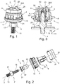
- FIGS. 1 and 3 illustrate an exemplary embodiment of a positioning element 1 according to the invention with which a component, for example a headlight housing of a motor vehicle, can be positioned and fixed in space relative to a support, in l 'the body of the motor vehicle.
- a component for example a headlight housing of a motor vehicle
- the positioning element 1 comprises several constituent parts which can all be made of plastic, for example by injection molding or by 3D printing or the like.
- the positioning element 1 according to the invention has been illustrated between a component indicated by the reference 7 and a support indicated by the reference 8.
- Positioning element 1 according to the embodiment shown on the Figures 1 to 3 comprises a bolt 2, a nut 3 which is screwed onto the bolt 2, a hollow body 4, a fixing element 5 and a locking element 6.
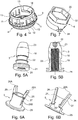
- the hollow body 4 is shown in perspective on the figure 4 .
- axially hollowed out like a mushroom. It comprises an axially hollowed-out head 10 which has a curved side facing outwards and a flat side facing inwards which forms a sealing washer coming into sealing contact with a plate pierced with the support 8.
- the head 10 is extended axially from the side turned inward by a foot 9 which is axially hollow with an annular edge forming a sort of passage which passes through the bore of the support plate 8.
- the interior of the foot 9 forms a cylindrical recess with an annular flat bottom joining the head 10 which serves as a shoulder.
- the hollow foot 9 has a cylindrical outer surface here which is provided with several flexible fingers 11 forming locking notches arranged in regular spacing around a circumference of the foot 9 and at a certain distance from the flat side of the head 10.
- the locking notches 11 protrude at rest towards the outside of the hollow foot 9 and are able to retract elastically and radially towards the inside of the foot 9 when the hollow foot 9 is inserted into the bore of the support plate 8 and to return elastically to their rest position at the end of the depression so that the locking notches 11 are positioned in abutment on the edge of the bore the support plate 8 for axially locking the hollow body 4 in the support plate 8.
- inclined slots 14 can be provided in the cylindrical wall of the hollow foot 9 which serve as cam guide grooves.
- Bolt 2 visible on figures 2 and 3 , here comprises on a first end 15 a first thread intended to be screwed into the component 7, and on a second end 16 a second thread cooperating here with the nut 3.
- the bolt 2 comprises an intermediate zone 17 here of hexagonal cross section which serves as a grip surface for screwing the bolt 2 into the component 7.
- Nut 3 illustrated on Figures 5A and 5B , is presented here as a cap nut with an external surface 18 shaped as a warhead and it is provided inside with a threaded bore 19 which cooperates with the threaded part 16 of the bolt 2.
- the opening 20 of the nut 3 is bordered by a flat crown 21 which extends radially outwards from the opening 20.
- the flat crown 21 is positioned inside the convex side of the head 10 of the hollow body 4.
- the outer surface of the nut 3 here forms in a median zone a peripheral annular groove 22 with straight edges for attachment.
- the nut 3 in the form of an ogive has here a closed frustoconical apex 23 which defines an imprint 40 adapted to receive a screwing tool (here a hexagon wrench) so as to be driven in rotation so as to be moved axially along the bolt 2.
- a screwing tool here a hexagon wrench
- the fixing element 5 and the bolt 2 are designed and adapted to hang on to each other by a reversible snap-in ensuring locking in the axial direction z.
- the fixing element 5 can be shaped to pinch the outside surface of the bolt 2 elastically.
- the fixing element 5 comprises a jaw formed by two arms 26 in opposition which act as spring lever arms.
- the two branches 26 are integral with the washer 25 which surrounds the second end 16 of the bolt 2 when the latter is pressed into the hollow body 4, this washer 25 being movable laterally in xy in the annular bottom of the hollow body 4 with respect to the axial direction z.
- the fastening element 5 shown here on the Figures 6A and 6B here comprises a sleeve coaxial with the washer 25 with an outer diameter smaller than the outer diameter of the washer 25, the sleeve and the washer 25 being in one piece.
- the sleeve of the fixing element 5 forms in its thickness the two arms 26 which have a rear part (rear) acting as a spring lever arm and a front part (front) which forms a jaw part.
- each branch 26 has a rotary articulation zone 27 which is connected to the sleeve and which is capable of deforming elastically by elastic torsion.
- the front (front) part of the branches 26 has a free end forming a hook 28 which is intended to engage in the annular groove 22 of the nut 3 to hang on the straight edges of this groove 22.
- the rear (rear) part 26A of the arms 26 extends obliquely along the axial direction z outside the sleeve of the fastening element 5 and above it so that the two rear parts 26A of the two branches 26 can be easily brought together manually from one another to separate the hook-shaped ends 28 at a right angle forming the jaw so as to release the attachment with the nut 3.
- the two rear parts 26A of the two arms 26 move away from one another, which causes the jaw to close.
- the articulation zone 27 has a spring effect and is constituted by the material of the upper edge of the sleeve of the fastening element 5 and the hooks 28 of the branches 26 project radially inwards from the sleeve through apertures 26B formed in the cylindrical surface of the sleeve of the fixing element 5.
- the locking element 6 illustrated in isolation on the figure 7 is presented as a kind of cylindrical bayonet socket with an axial bore 30.
- the locking element 6 is designed to be inserted axially in the hollow body 4 around the fixing element 5 to tighten the washer 25 against the annular shoulder of the hollow body 4.
- the blocking element 6 in the form of a bayonet socket has two diametrically opposite lugs 31 which project radially to engage respectively in the inclined slots 14 or cam guide grooves formed in the foot 9 of the hollow body 4.
- the bayonet socket 6 has an annular base which has an internal diameter which is less than the outside diameter of the washer 25 but which is greater than that of the sleeve of the fixing element 5.
- the bayonet socket 6 has here an external surface 32 which forms an imprint here hexagonal intended to cooperate with a tool in order to apply to the locking element 6 an angular rotation in the hollow body 4, this rotation resulting by a cam effect of the pins 31 in the slots 14, a axial displacement of the locking element 6 towards the bottom of the hollow body 4 and a tightening of the washer 25 between the bayonet socket 6 and the bottom of the hollow body 4.
- the tightening is here achieved by an angular rotation of one eighth of bayonet socket 6.
- locking element 6 of different shape, for example a hollow bolt which is screwed into a thread of the hollow body.
- the principle of use of the positioning element 1 is as follows.
- the mushroom-shaped hollow body 4 is first inserted axially locked in a circular hole in the support 8.
- the head 10 of the hollow body 4 comes to bear against one face of the support 8 and provides leak-tightness through the circular hole .
- the fixing element 5 with the arms 26 with lever arms is then inserted inside the foot 9 of the hollow body 4, the washer 25 lying flat on the annular bottom of the hollow body 4.
- the locking element 6 in the form of a bayonet socket is then placed in the hollow body 4 which is provided with two diametrically opposed axial grooves (designated by 13 on the figure 4 ) which are formed in the inner surface of the foot and which open into the slots 14 so as to be able to bring the pins 31 to the slots 14 of the hollow body 4 by an axial translation.
- the bolt 2 is fixed to the component by screwing and is coated with the profiled nut 3 which is screwed as far as possible up to the intermediate zone 17.
- the shaped nut 3 in the shape of a warhead screwed on the bolt 2 (and with the component) is presented facing the head 10 of the hollow body 4 and the shaped nut 3 is inserted through it in the foot 9 of the hollow body 4.
- the frustoconical end of the profiled nut 3 then enters the sleeve of the fixing element 5, spreads elastically the front parts (front) of the two branches 26 until the latter pinches the groove 22 and hooks there by snap-fastening.
- This arrangement has the advantage of making it possible to disassemble the bolt 2 outside the hollow body 4 without modifying the xyz settings due to the reversible snap-fastening. Indeed, it suffices to click the branches 26 with lever arms of the groove 22 by bringing them closer to one another to move the hooks 28 apart and separate them from the groove 22.
- the nut 3 profiled with the bolt 2 can then be removed axially from the hollow body 4, then again be inserted axially (for example after working on the component 8) in the hollow body 4 while retaining the positioning settings in xyz.
- the arrangement of the positioning element 1 according to the invention also allows adjustment of position in xy and then adjustment of position in z.
- the various parts 2, 3, 4, 5, 6 of the positioning element 1 according to the invention can be produced at low cost by molding plastic material and even if it is a production in small series by example by adding material to a 3D printer.
- the different parts of the positioning element 1 according to the invention could have a shape different from that presented in the drawings as long as the attachment of the bolt 2 with the fixing element 5 to the washer is carried out. by a reversible snap.
- the fixing element 5 could have only one branch 26 with a lever arm.
- the latching could also be done by an elastic ring type "circlip” or the like.
Landscapes
- Engineering & Computer Science (AREA)
- General Engineering & Computer Science (AREA)
- Mechanical Engineering (AREA)
- Bolts, Nuts, And Washers (AREA)
- Dowels (AREA)
- Dental Prosthetics (AREA)
Claims (12)
- Einstellbares Positionierelement (1), mit dem eine Komponente (7) im Raum positioniert und fixiert werden kann, umfassend einen Bolzen (2), mit dem die Komponente (7) in eine axiale Richtung (z) des Bolzens (2) positioniert werden kann, einen hohlen Korpus (4), der einen ringförmigen Grund aufweist, der von dem Bolzen (2) durchsetzt ist, dadurch gekennzeichnet,
dass es ein Fixierelement (5) mit einer den Bolzen (2) umgebenden Scheibe (25), die in Bezug auf die axiale Richtung in dem Grund des hohlen Korpus (4) seitwärts beweglich verlagerbar ist, umfasst, wobei die Scheibe (25) vorgesehen ist, um in den Grund des hohlen Korpus (4) gepresst zu werden, wenn das Fixierelement (5) an den Bolzen (2) derart angeschlossen wird, um die seitliche Position des Bolzens (2) in dem hohlen Korpus (4) zu fixieren, und dass das Fixierelement (5) und der Bolzen (2) ausgebildet sind, um sich gegenseitig durch reversibles Verrasten zu befestigen. - Positionierelement (1) nach Anspruch 1, dadurch gekennzeichnet, dass das Fixierelement (5) ausgebildet ist zum Klemmen des Bolzens (2) zum Verwirklichen der Verrastung.
- Positionierelement (1) nach Anspruch 2, dadurch gekennzeichnet, dass das Fixierelement (5) eine durch zwei gegenüberliegende Schenkel (26) gebildete Klaue umfasst, welche wie federnde Hebelarme wirken.
- Positionierelement (1) nach Anspruch 2, dadurch gekennzeichnet, dass eine Mutter (3) auf den Bolzen (2) geschraubt ist, und dass das Fixierelement (5) auf der Mutter (3) verrastet ist.
- Positionierelement (1) nach Anspruch 4, dadurch gekennzeichnet, dass die Mutter (3) mit einer umlaufenden Nut (22) versehen ist, in die das Fixierelement (5) klemmend eindringt.
- Positionierelement (1) nach Anspruch 1, dadurch gekennzeichnet, dass die Scheibe (25) in den Grund des hohlen Korpus (4) mittels eines rotierbaren Blockierelements (6) in dem hohlen Korpus (4) gepresst ist.
- Positionierelement (1) nach Anspruch 5, dadurch gekennzeichnet, dass das rotierbare Blockierelement (6) eine Bajonett-Hülse ist, die sich in dem hohlen Korpus (4) durch Verdrehung verriegelt.
- Positionierelement (1) nach Anspruch 3, dadurch gekennzeichnet, dass die Scheibe (25) und die Schenkel (26) einteilig ausgebildet sind.
- Positionierelement (1) nach Anspruch 4, dadurch gekennzeichnet, dass die Mutter (2) die Gestalt eines Geschosses mit einem Gipfel aufweist, der eine für die Aufnahme eines Schraubwerkzeugs angepasste Vertiefung (40) aufweist.
- Positionierelement (1) nach Anspruch 6, dadurch gekennzeichnet, dass das rotierbare Blockierelement (6) eine zur Aufnahme eines Schraubwerkzeugs ausgebildete Vertiefung bildet.
- Positionierelement (1) nach einem der vorhergehenden Ansprüche, dadurch gekennzeichnet, dass der hohle Korpus (4) die Gestalt eines axial ausgehöhlten Pilzes aufweist, mit einem Kopf (10), der eine Abdichtoberfläche aufweist, und einem Fuß (9), der Blockierrasten umfasst.
- Positionierelement (1) nach einem der vorhergehenden Ansprüche, dadurch gekennzeichnet, dass es vollständig aus Kunststoffmaterial hergestellt ist.
Applications Claiming Priority (2)
| Application Number | Priority Date | Filing Date | Title |
|---|---|---|---|
| FR1560888A FR3043736B1 (fr) | 2015-11-13 | 2015-11-13 | Element de positionnement d'un composant dans l'espace |
| PCT/FR2016/052901 WO2017081404A1 (fr) | 2015-11-13 | 2016-11-09 | Element de positionnement d'un composant dans l'espace |
Publications (2)
| Publication Number | Publication Date |
|---|---|
| EP3374647A1 EP3374647A1 (de) | 2018-09-19 |
| EP3374647B1 true EP3374647B1 (de) | 2020-01-01 |
Family
ID=55236619
Family Applications (1)
| Application Number | Title | Priority Date | Filing Date |
|---|---|---|---|
| EP16809969.5A Active EP3374647B1 (de) | 2015-11-13 | 2016-11-09 | Element zur positionierung einer komponente im raum |
Country Status (5)
| Country | Link |
|---|---|
| US (1) | US10851819B2 (de) |
| EP (1) | EP3374647B1 (de) |
| CN (2) | CN206290560U (de) |
| FR (1) | FR3043736B1 (de) |
| WO (1) | WO2017081404A1 (de) |
Families Citing this family (11)
| Publication number | Priority date | Publication date | Assignee | Title |
|---|---|---|---|---|
| FR3043736B1 (fr) * | 2015-11-13 | 2017-11-24 | A Raymond Et Cie | Element de positionnement d'un composant dans l'espace |
| DE102017131235A1 (de) * | 2017-12-22 | 2019-06-27 | Witte Automotive Gmbh | Toleranzausgleichsvorrichtung |
| CN108799270B (zh) * | 2018-06-06 | 2021-02-26 | 北京长城华冠汽车科技股份有限公司 | 车辆安装件组件和具有其的车辆 |
| CN109914819B (zh) * | 2019-03-01 | 2024-04-26 | 广东中集建筑制造有限公司 | 用于建筑模块的运输支腿和建筑模块装置 |
| EP3705738B1 (de) * | 2019-03-04 | 2023-05-10 | ZKW Group GmbH | Kunststofftechnik-schraube-leichtmetall-bauteil-befestigungssystem und verfahren zum einschrauben von kunststofftechnik-schrauben in leichtmetalle |
| ES2861160B2 (es) * | 2019-12-05 | 2022-04-27 | Seat Sa | Dispositivo de acoplamiento |
| CN112319359B (zh) * | 2020-10-30 | 2021-12-21 | 浙江零跑科技股份有限公司 | 一种汽车尾灯的安装方法 |
| US12060016B2 (en) * | 2021-01-18 | 2024-08-13 | Stephen E. Wilson | Mounting devices for ornaments |
| DE102023102634A1 (de) * | 2023-02-02 | 2024-08-08 | Böllhoff Verbindungstechnik GmbH | Verstellelement mit dämpfender Befestigungshülse sowie ein Installations- und ein Herstellungsverfahren dafür |
| DE102023103194A1 (de) | 2023-02-09 | 2024-08-14 | Böllhoff Verbindungstechnik GmbH | Verbindungselement zweier zueinander beabstandeter Bauteile mit Toleranzausgleichsfunktion sowie ein Installationsverfahren dafür |
| CN119636565A (zh) * | 2023-09-15 | 2025-03-18 | 维特汽车有限责任公司 | 一种带有保护元件的连接结构和一种车辆装置 |
Family Cites Families (19)
| Publication number | Priority date | Publication date | Assignee | Title |
|---|---|---|---|---|
| FR2621361B1 (fr) * | 1987-10-05 | 1990-01-12 | Materiel Equip Tech Cie | Perfectionnements aux systemes de fixation comportant des ecrous emprisonnes dans des cages |
| US5173025A (en) * | 1991-12-26 | 1992-12-22 | Nifco Inc. | Screw grommet having a secured internal thread member |
| US5374136A (en) * | 1992-12-11 | 1994-12-20 | A-Dec. Inc. | Mounting mechanism |
| FR2736974B1 (fr) * | 1995-07-21 | 1997-08-29 | Rapid Sa | Attache pour la fixation reglable de deux pieces espacees |
| JP3216788B2 (ja) * | 1996-02-08 | 2001-10-09 | 矢崎総業株式会社 | コネクタ保持構造 |
| WO2002048557A1 (en) | 2000-12-16 | 2002-06-20 | Southco, Inc. | Captive screw |
| TWI309279B (en) | 2002-12-18 | 2009-05-01 | Southco | Low profile captive screw |
| DE10354062A1 (de) * | 2003-11-15 | 2005-06-16 | Witte-Velbert Gmbh & Co. Kg | Vorrichtung zum Verbinden zweier Bauteile in einer Abstandsstellung zueinander |
| DE102005032699B4 (de) * | 2005-07-14 | 2007-08-23 | Itw Automotive Products Gmbh & Co. Kg | Befestigungsvorrichtung |
| DE102006034463B3 (de) * | 2006-07-26 | 2008-01-10 | A. Raymond Et Cie | Vorrichtung zum Befestigen eines Anbauteiles und eines Trägerteiles in einem Abstand voneinander |
| DE202007016945U1 (de) * | 2007-12-05 | 2008-05-15 | Böllhoff Verbindungstechnik GmbH | Verstellelement |
| DE202008002633U1 (de) | 2008-02-25 | 2008-05-08 | Böllhoff Verbindungstechnik GmbH | Befestigungsanordnung mit selbsttätigem dreidimensionalem Toleranzausgleich |
| DE102008062894B4 (de) * | 2008-12-12 | 2011-07-21 | Hans und Ottmar Binder GbR (vertretungsberechtigte Gesellschafter: Hans Binder, 89558 Böhmenkirch; Ottmar Binder, 89558 Böhmenkirch), 89558 | Distanzvorrichtung und Befestigungsanordnung mit Distanzvorrichtung |
| EP2611973B1 (de) * | 2010-09-03 | 2014-05-14 | Eczacibasi Yapi Gerecleri San. Ve Tic. A.s. | Wassertankinstallationssystem |
| US20130170895A1 (en) * | 2012-01-03 | 2013-07-04 | Ying-Chih Tseng | Floating fastener with expanded application flexibility |
| US9829021B2 (en) * | 2013-01-02 | 2017-11-28 | Illinois Tool Works Inc. | Compensation nut fastener assembly |
| FR3003910B1 (fr) * | 2013-03-26 | 2015-08-21 | Peugeot Citroen Automobiles Sa | Dispositif de fixation comportant un pion monte reglable dans un corps, suivant deux positions axiales |
| US9127701B2 (en) * | 2013-05-31 | 2015-09-08 | Marine Town Inc. | Fastening device |
| FR3043736B1 (fr) | 2015-11-13 | 2017-11-24 | A Raymond Et Cie | Element de positionnement d'un composant dans l'espace |
-
2015
- 2015-11-13 FR FR1560888A patent/FR3043736B1/fr active Active
-
2016
- 2016-11-09 WO PCT/FR2016/052901 patent/WO2017081404A1/fr not_active Ceased
- 2016-11-09 CN CN201621210390.6U patent/CN206290560U/zh not_active Withdrawn - After Issue
- 2016-11-09 EP EP16809969.5A patent/EP3374647B1/de active Active
- 2016-11-09 CN CN201610987557.8A patent/CN106870542B/zh not_active Expired - Fee Related
- 2016-11-09 US US15/774,980 patent/US10851819B2/en not_active Expired - Fee Related
Non-Patent Citations (1)
| Title |
|---|
| None * |
Also Published As
| Publication number | Publication date |
|---|---|
| CN206290560U (zh) | 2017-06-30 |
| WO2017081404A1 (fr) | 2017-05-18 |
| CN106870542B (zh) | 2018-10-16 |
| US10851819B2 (en) | 2020-12-01 |
| EP3374647A1 (de) | 2018-09-19 |
| FR3043736A1 (fr) | 2017-05-19 |
| CN106870542A (zh) | 2017-06-20 |
| FR3043736B1 (fr) | 2017-11-24 |
| US20180328390A1 (en) | 2018-11-15 |
Similar Documents
| Publication | Publication Date | Title |
|---|---|---|
| WO2017081404A1 (fr) | Element de positionnement d'un composant dans l'espace | |
| EP3546685B1 (de) | Justiervorrichtung zum anheben eines werkstücks | |
| FR2568958A1 (fr) | Joint a rotule | |
| FR2882797A1 (fr) | Attache adaptee a etre fixee dans une cavite de contour predetermine | |
| FR3061119B1 (fr) | Dispositif d’ecartement a rattrapage angulaire | |
| EP3848154A1 (de) | Heftklammer mit ausgerichteter klammerzange | |
| EP0797718B1 (de) | Provisorischer türanschlag für ein kraftfahrzeugscharnier und vorrichtung um diesen anzubringen | |
| FR2675219A1 (fr) | Dispositif de fixation destine a retenir en une position determinee une premiere piece sur une seconde piece. | |
| FR2736974A1 (fr) | Attache pour la fixation reglable de deux pieces espacees | |
| EP4100211B1 (de) | Rundklammer mit festem trennsteg | |
| EP2841774B1 (de) | Element zur befestigung eines zubehörteils an einer halterung und der halterung an einer struktur | |
| EP3312053B1 (de) | Befestigungsanordnung für aufklappbegrenzung einer hinteren ablage auf der heckklappe eines kraftfahrzeugs | |
| FR2954428A1 (fr) | Dispositif limiteur de couple et bouchon pour tete de tubulure comportant un tel dispositif | |
| FR2897908A1 (fr) | Agencement de fixation | |
| FR3073021B1 (fr) | Ensemble comportant un panneau et un systeme de fixation | |
| FR2821800A1 (fr) | Dispositif de remplissage de reservoir a carburant | |
| WO1998053214A1 (fr) | Dispositif de fixation d'un element a un support mince | |
| FR2607201A1 (fr) | Dispositif de fixation sur fut filete ou annele | |
| EP3803001B1 (de) | Vorhängeschlossvorrichtung und verfahren zum zusammenbau einer solchen vorrichtung | |
| FR2715199A1 (fr) | Dispositif de fixation d'un équipement sur la carrosserie d'un véhicule automobile. | |
| EP0761988A1 (de) | Vorrichtung zum Befestigen eines Teils, insbesondere eines Elektromagnetventils einer Waschmaschine, auf einer Trägerplatte | |
| FR3036068A1 (fr) | Dispositif d'accrochage pour l'accrochage d'un pot d'echappement a la caisse d'un vehicule automobile | |
| FR3070742A1 (fr) | Agrafe demontable pour la fixation d'elements allonges sur un support a bord d'un vehicule automobile | |
| FR2621177A1 (fr) | Support pour tiges metalliques orientables, plus particulierement pour antennes de vehicules automobiles | |
| CH363863A (fr) | Dispositif de fixation |
Legal Events
| Date | Code | Title | Description |
|---|---|---|---|
| STAA | Information on the status of an ep patent application or granted ep patent |
Free format text: STATUS: UNKNOWN |
|
| STAA | Information on the status of an ep patent application or granted ep patent |
Free format text: STATUS: THE INTERNATIONAL PUBLICATION HAS BEEN MADE |
|
| PUAI | Public reference made under article 153(3) epc to a published international application that has entered the european phase |
Free format text: ORIGINAL CODE: 0009012 |
|
| STAA | Information on the status of an ep patent application or granted ep patent |
Free format text: STATUS: REQUEST FOR EXAMINATION WAS MADE |
|
| 17P | Request for examination filed |
Effective date: 20180613 |
|
| AK | Designated contracting states |
Kind code of ref document: A1 Designated state(s): AL AT BE BG CH CY CZ DE DK EE ES FI FR GB GR HR HU IE IS IT LI LT LU LV MC MK MT NL NO PL PT RO RS SE SI SK SM TR |
|
| AX | Request for extension of the european patent |
Extension state: BA ME |
|
| RIN1 | Information on inventor provided before grant (corrected) |
Inventor name: COCHARD, MATHIEU Inventor name: DEPAIL, YVES-MARIE |
|
| DAV | Request for validation of the european patent (deleted) | ||
| DAX | Request for extension of the european patent (deleted) | ||
| GRAP | Despatch of communication of intention to grant a patent |
Free format text: ORIGINAL CODE: EPIDOSNIGR1 |
|
| STAA | Information on the status of an ep patent application or granted ep patent |
Free format text: STATUS: GRANT OF PATENT IS INTENDED |
|
| INTG | Intention to grant announced |
Effective date: 20190715 |
|
| GRAS | Grant fee paid |
Free format text: ORIGINAL CODE: EPIDOSNIGR3 |
|
| GRAA | (expected) grant |
Free format text: ORIGINAL CODE: 0009210 |
|
| STAA | Information on the status of an ep patent application or granted ep patent |
Free format text: STATUS: THE PATENT HAS BEEN GRANTED |
|
| AK | Designated contracting states |
Kind code of ref document: B1 Designated state(s): AL AT BE BG CH CY CZ DE DK EE ES FI FR GB GR HR HU IE IS IT LI LT LU LV MC MK MT NL NO PL PT RO RS SE SI SK SM TR |
|
| REG | Reference to a national code |
Ref country code: GB Ref legal event code: FG4D Free format text: NOT ENGLISH |
|
| REG | Reference to a national code |
Ref country code: CH Ref legal event code: EP Ref country code: AT Ref legal event code: REF Ref document number: 1220117 Country of ref document: AT Kind code of ref document: T Effective date: 20200115 |
|
| REG | Reference to a national code |
Ref country code: DE Ref legal event code: R096 Ref document number: 602016027498 Country of ref document: DE |
|
| REG | Reference to a national code |
Ref country code: IE Ref legal event code: FG4D Free format text: LANGUAGE OF EP DOCUMENT: FRENCH |
|
| REG | Reference to a national code |
Ref country code: NL Ref legal event code: MP Effective date: 20200101 |
|
| REG | Reference to a national code |
Ref country code: LT Ref legal event code: MG4D |
|
| PG25 | Lapsed in a contracting state [announced via postgrant information from national office to epo] |
Ref country code: FI Free format text: LAPSE BECAUSE OF FAILURE TO SUBMIT A TRANSLATION OF THE DESCRIPTION OR TO PAY THE FEE WITHIN THE PRESCRIBED TIME-LIMIT Effective date: 20200101 Ref country code: NO Free format text: LAPSE BECAUSE OF FAILURE TO SUBMIT A TRANSLATION OF THE DESCRIPTION OR TO PAY THE FEE WITHIN THE PRESCRIBED TIME-LIMIT Effective date: 20200401 Ref country code: LT Free format text: LAPSE BECAUSE OF FAILURE TO SUBMIT A TRANSLATION OF THE DESCRIPTION OR TO PAY THE FEE WITHIN THE PRESCRIBED TIME-LIMIT Effective date: 20200101 Ref country code: PT Free format text: LAPSE BECAUSE OF FAILURE TO SUBMIT A TRANSLATION OF THE DESCRIPTION OR TO PAY THE FEE WITHIN THE PRESCRIBED TIME-LIMIT Effective date: 20200527 Ref country code: CZ Free format text: LAPSE BECAUSE OF FAILURE TO SUBMIT A TRANSLATION OF THE DESCRIPTION OR TO PAY THE FEE WITHIN THE PRESCRIBED TIME-LIMIT Effective date: 20200101 Ref country code: NL Free format text: LAPSE BECAUSE OF FAILURE TO SUBMIT A TRANSLATION OF THE DESCRIPTION OR TO PAY THE FEE WITHIN THE PRESCRIBED TIME-LIMIT Effective date: 20200101 Ref country code: RS Free format text: LAPSE BECAUSE OF FAILURE TO SUBMIT A TRANSLATION OF THE DESCRIPTION OR TO PAY THE FEE WITHIN THE PRESCRIBED TIME-LIMIT Effective date: 20200101 |
|
| PG25 | Lapsed in a contracting state [announced via postgrant information from national office to epo] |
Ref country code: GR Free format text: LAPSE BECAUSE OF FAILURE TO SUBMIT A TRANSLATION OF THE DESCRIPTION OR TO PAY THE FEE WITHIN THE PRESCRIBED TIME-LIMIT Effective date: 20200402 Ref country code: HR Free format text: LAPSE BECAUSE OF FAILURE TO SUBMIT A TRANSLATION OF THE DESCRIPTION OR TO PAY THE FEE WITHIN THE PRESCRIBED TIME-LIMIT Effective date: 20200101 Ref country code: LV Free format text: LAPSE BECAUSE OF FAILURE TO SUBMIT A TRANSLATION OF THE DESCRIPTION OR TO PAY THE FEE WITHIN THE PRESCRIBED TIME-LIMIT Effective date: 20200101 Ref country code: SE Free format text: LAPSE BECAUSE OF FAILURE TO SUBMIT A TRANSLATION OF THE DESCRIPTION OR TO PAY THE FEE WITHIN THE PRESCRIBED TIME-LIMIT Effective date: 20200101 Ref country code: IS Free format text: LAPSE BECAUSE OF FAILURE TO SUBMIT A TRANSLATION OF THE DESCRIPTION OR TO PAY THE FEE WITHIN THE PRESCRIBED TIME-LIMIT Effective date: 20200501 Ref country code: BG Free format text: LAPSE BECAUSE OF FAILURE TO SUBMIT A TRANSLATION OF THE DESCRIPTION OR TO PAY THE FEE WITHIN THE PRESCRIBED TIME-LIMIT Effective date: 20200401 |
|
| REG | Reference to a national code |
Ref country code: DE Ref legal event code: R097 Ref document number: 602016027498 Country of ref document: DE |
|
| PG25 | Lapsed in a contracting state [announced via postgrant information from national office to epo] |
Ref country code: RO Free format text: LAPSE BECAUSE OF FAILURE TO SUBMIT A TRANSLATION OF THE DESCRIPTION OR TO PAY THE FEE WITHIN THE PRESCRIBED TIME-LIMIT Effective date: 20200101 Ref country code: SM Free format text: LAPSE BECAUSE OF FAILURE TO SUBMIT A TRANSLATION OF THE DESCRIPTION OR TO PAY THE FEE WITHIN THE PRESCRIBED TIME-LIMIT Effective date: 20200101 Ref country code: EE Free format text: LAPSE BECAUSE OF FAILURE TO SUBMIT A TRANSLATION OF THE DESCRIPTION OR TO PAY THE FEE WITHIN THE PRESCRIBED TIME-LIMIT Effective date: 20200101 Ref country code: DK Free format text: LAPSE BECAUSE OF FAILURE TO SUBMIT A TRANSLATION OF THE DESCRIPTION OR TO PAY THE FEE WITHIN THE PRESCRIBED TIME-LIMIT Effective date: 20200101 Ref country code: ES Free format text: LAPSE BECAUSE OF FAILURE TO SUBMIT A TRANSLATION OF THE DESCRIPTION OR TO PAY THE FEE WITHIN THE PRESCRIBED TIME-LIMIT Effective date: 20200101 Ref country code: SK Free format text: LAPSE BECAUSE OF FAILURE TO SUBMIT A TRANSLATION OF THE DESCRIPTION OR TO PAY THE FEE WITHIN THE PRESCRIBED TIME-LIMIT Effective date: 20200101 |
|
| PLBE | No opposition filed within time limit |
Free format text: ORIGINAL CODE: 0009261 |
|
| STAA | Information on the status of an ep patent application or granted ep patent |
Free format text: STATUS: NO OPPOSITION FILED WITHIN TIME LIMIT |
|
| REG | Reference to a national code |
Ref country code: AT Ref legal event code: MK05 Ref document number: 1220117 Country of ref document: AT Kind code of ref document: T Effective date: 20200101 |
|
| 26N | No opposition filed |
Effective date: 20201002 |
|
| PG25 | Lapsed in a contracting state [announced via postgrant information from national office to epo] |
Ref country code: IT Free format text: LAPSE BECAUSE OF FAILURE TO SUBMIT A TRANSLATION OF THE DESCRIPTION OR TO PAY THE FEE WITHIN THE PRESCRIBED TIME-LIMIT Effective date: 20200101 Ref country code: AT Free format text: LAPSE BECAUSE OF FAILURE TO SUBMIT A TRANSLATION OF THE DESCRIPTION OR TO PAY THE FEE WITHIN THE PRESCRIBED TIME-LIMIT Effective date: 20200101 |
|
| PG25 | Lapsed in a contracting state [announced via postgrant information from national office to epo] |
Ref country code: PL Free format text: LAPSE BECAUSE OF FAILURE TO SUBMIT A TRANSLATION OF THE DESCRIPTION OR TO PAY THE FEE WITHIN THE PRESCRIBED TIME-LIMIT Effective date: 20200101 Ref country code: SI Free format text: LAPSE BECAUSE OF FAILURE TO SUBMIT A TRANSLATION OF THE DESCRIPTION OR TO PAY THE FEE WITHIN THE PRESCRIBED TIME-LIMIT Effective date: 20200101 |
|
| PG25 | Lapsed in a contracting state [announced via postgrant information from national office to epo] |
Ref country code: MC Free format text: LAPSE BECAUSE OF FAILURE TO SUBMIT A TRANSLATION OF THE DESCRIPTION OR TO PAY THE FEE WITHIN THE PRESCRIBED TIME-LIMIT Effective date: 20200101 |
|
| REG | Reference to a national code |
Ref country code: CH Ref legal event code: PL |
|
| GBPC | Gb: european patent ceased through non-payment of renewal fee |
Effective date: 20201109 |
|
| PG25 | Lapsed in a contracting state [announced via postgrant information from national office to epo] |
Ref country code: LU Free format text: LAPSE BECAUSE OF NON-PAYMENT OF DUE FEES Effective date: 20201109 |
|
| REG | Reference to a national code |
Ref country code: BE Ref legal event code: MM Effective date: 20201130 |
|
| PG25 | Lapsed in a contracting state [announced via postgrant information from national office to epo] |
Ref country code: LI Free format text: LAPSE BECAUSE OF NON-PAYMENT OF DUE FEES Effective date: 20201130 Ref country code: CH Free format text: LAPSE BECAUSE OF NON-PAYMENT OF DUE FEES Effective date: 20201130 |
|
| PG25 | Lapsed in a contracting state [announced via postgrant information from national office to epo] |
Ref country code: IE Free format text: LAPSE BECAUSE OF NON-PAYMENT OF DUE FEES Effective date: 20201109 |
|
| PG25 | Lapsed in a contracting state [announced via postgrant information from national office to epo] |
Ref country code: GB Free format text: LAPSE BECAUSE OF NON-PAYMENT OF DUE FEES Effective date: 20201109 |
|
| PGFP | Annual fee paid to national office [announced via postgrant information from national office to epo] |
Ref country code: DE Payment date: 20211118 Year of fee payment: 6 |
|
| PG25 | Lapsed in a contracting state [announced via postgrant information from national office to epo] |
Ref country code: TR Free format text: LAPSE BECAUSE OF FAILURE TO SUBMIT A TRANSLATION OF THE DESCRIPTION OR TO PAY THE FEE WITHIN THE PRESCRIBED TIME-LIMIT Effective date: 20200101 Ref country code: MT Free format text: LAPSE BECAUSE OF FAILURE TO SUBMIT A TRANSLATION OF THE DESCRIPTION OR TO PAY THE FEE WITHIN THE PRESCRIBED TIME-LIMIT Effective date: 20200101 Ref country code: CY Free format text: LAPSE BECAUSE OF FAILURE TO SUBMIT A TRANSLATION OF THE DESCRIPTION OR TO PAY THE FEE WITHIN THE PRESCRIBED TIME-LIMIT Effective date: 20200101 |
|
| PG25 | Lapsed in a contracting state [announced via postgrant information from national office to epo] |
Ref country code: MK Free format text: LAPSE BECAUSE OF FAILURE TO SUBMIT A TRANSLATION OF THE DESCRIPTION OR TO PAY THE FEE WITHIN THE PRESCRIBED TIME-LIMIT Effective date: 20200101 Ref country code: AL Free format text: LAPSE BECAUSE OF FAILURE TO SUBMIT A TRANSLATION OF THE DESCRIPTION OR TO PAY THE FEE WITHIN THE PRESCRIBED TIME-LIMIT Effective date: 20200101 |
|
| PG25 | Lapsed in a contracting state [announced via postgrant information from national office to epo] |
Ref country code: BE Free format text: LAPSE BECAUSE OF NON-PAYMENT OF DUE FEES Effective date: 20201130 |
|
| REG | Reference to a national code |
Ref country code: DE Ref legal event code: R119 Ref document number: 602016027498 Country of ref document: DE |
|
| P01 | Opt-out of the competence of the unified patent court (upc) registered |
Effective date: 20230526 |
|
| PG25 | Lapsed in a contracting state [announced via postgrant information from national office to epo] |
Ref country code: DE Free format text: LAPSE BECAUSE OF NON-PAYMENT OF DUE FEES Effective date: 20230601 |
|
| PGFP | Annual fee paid to national office [announced via postgrant information from national office to epo] |
Ref country code: FR Payment date: 20251126 Year of fee payment: 10 |