EP3312053B1 - Befestigungsanordnung für aufklappbegrenzung einer hinteren ablage auf der heckklappe eines kraftfahrzeugs - Google Patents
Befestigungsanordnung für aufklappbegrenzung einer hinteren ablage auf der heckklappe eines kraftfahrzeugs Download PDFInfo
- Publication number
- EP3312053B1 EP3312053B1 EP17191954.1A EP17191954A EP3312053B1 EP 3312053 B1 EP3312053 B1 EP 3312053B1 EP 17191954 A EP17191954 A EP 17191954A EP 3312053 B1 EP3312053 B1 EP 3312053B1
- Authority
- EP
- European Patent Office
- Prior art keywords
- base
- assembly
- head
- door
- radius
- Prior art date
- Legal status (The legal status is an assumption and is not a legal conclusion. Google has not performed a legal analysis and makes no representation as to the accuracy of the status listed.)
- Active
Links
Images
Classifications
-
- B—PERFORMING OPERATIONS; TRANSPORTING
- B60—VEHICLES IN GENERAL
- B60R—VEHICLES, VEHICLE FITTINGS, OR VEHICLE PARTS, NOT OTHERWISE PROVIDED FOR
- B60R5/00—Compartments within vehicle body primarily intended or sufficiently spacious for trunks, suit-cases, or the like
- B60R5/04—Compartments within vehicle body primarily intended or sufficiently spacious for trunks, suit-cases, or the like arranged at rear of vehicle
- B60R5/044—Compartments within vehicle body primarily intended or sufficiently spacious for trunks, suit-cases, or the like arranged at rear of vehicle luggage covering means, e.g. parcel shelves
-
- B—PERFORMING OPERATIONS; TRANSPORTING
- B60—VEHICLES IN GENERAL
- B60R—VEHICLES, VEHICLE FITTINGS, OR VEHICLE PARTS, NOT OTHERWISE PROVIDED FOR
- B60R5/00—Compartments within vehicle body primarily intended or sufficiently spacious for trunks, suit-cases, or the like
- B60R5/04—Compartments within vehicle body primarily intended or sufficiently spacious for trunks, suit-cases, or the like arranged at rear of vehicle
Definitions
- the present invention relates to the rear shelves of motor vehicles which are retractable storage shelves fitted to the rear parts of certain motor vehicles.
- It relates more particularly to a set of fixing a travel limiter of a rear shelf on the rear door of a vehicle.
- the document DE 20 2009 004 736 U1 discloses a fixing assembly of a travel limit limiter of a rear shelf of a motor vehicle according to the preamble of claim 1.
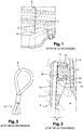
- a rear shelf 1 of a motor vehicle is rotatably mounted relative to the body structure (not shown) of the vehicle.
- the tablet 1 is provided with one or two flexible cords 2 (only one cord is shown on the figure 1 ), also called travel limiters, a first end 3 is secured to the tablet 1 and a second end 4, free, can be provided with a loop 5 ( Fig. 3 ) to removably fix the cord 2 the tailgate, also called the rear flap 6 ( Fig. 2 ).
- the shelf 1 is arranged in such a way that when the rear door 6 is rotated, for the opening of the trunk, the shelf 1 is also rotated by means of the travel limiters 2.
- the loop 5 is able to be threaded removably onto a base 7 integral with the inner lining 8 of the flap 6.
- the projecting portion of the base 7, or head 9, defines a flange 10 with rounded edges.
- the base 7 further comprises a groove 11 adapted to receive the loop 5.
- the loop 5 can be replaced by a tip 12 secured to the end 10B of the limiter 2 and which is adapted to be clipped onto the head 9 of the base 7.
- the tip 12 has a cavity 13 delimited by antagonistic deformable tabs 14, integral with the tip 12, and whose ends terminate in stops.
- the tabs 14 move apart when the nozzle 12 is pressed on the head 9 by elastic deformation of the tabs 14 and, with the head 9 passed, the ends of the tabs 14 provided with the stops are tightened behind the head 9 in the groove 11 formed behind the head 9 of the base 7 ensuring the removable attachment of the nozzle assembly 12 / base 7.
- a tip 12 clipped on the base 7 is more immediate than the threading of a loop 5.
- the tip 12 must respect an offset angle ⁇ sufficient to accompany the rotation of the flap 1 without risk unclipping the nozzle 12.
- the axis of rotation of the tablet is parallel to the axis passing through the hinges solidarisant rotation the flap on the rear upper part of the vehicle body.
- the maximum offset angle ⁇ of the tip on the base is limited to 5 °. This angle ⁇ may not be insufficient for arrangements of shelf 1 / rear flap 6 requiring high deflections (offset angle ⁇ greater than 5 °); an offset angle ⁇ insufficient that can lead to inadvertent declipping of the tip 12.
- the force required to unclip the tip 12 of the head 9 may be conducive to tearing the base 7 fixed directly to the lining 8 of the flap 6.
- the object of the present invention is to provide an attachment assembly for accepting a larger angle offset between the tip and the base.
- This solution provides more freedom in the positioning of the base to take into account the difference in stretching of the cord between the positions of the closed or open shelf for which there can be a delta of 150% of the length of the cord .
- the present invention provides a gain in terms of transversality since it can adapt to several vehicle models (high end or low end).
- Fixing the base also has the advantage of keeping the lining robustly on the flap.
- the cord remains tight throughout the opening and closing kinematics of the shutter. What avoids having a cordon that has the state of closure of the shutter hangs in part on the shelf which can affect the aesthetic effect.
- the subject of the invention is an assembly for attaching a travel limiter of a rear shelf of a motor vehicle to the rear door of said vehicle, said limiter being provided with at least one cord, a first end is secured to the rear shelf and a second end of which is provided with a first fastening element capable of being releasably secured to a base secured to the flap, characterized in that the body of the base comprises a head forming a solid spherical cap adapted to receive the first fastening element and a fastening interface adapted to secure the base on the shutter.
- the cap has a specific height and radius; the height of the cap being greater than its radius.
- the fixing interface delimits with the head of the base a groove of determined width, adapted to receive the first fastening element.
- the first fastening element is a loop capable of being threaded between the head and the interface for fixing the base inside the groove.
- the attachment interface defines a flange having a groove oriented towards the groove ensuring the centering of the loop in the groove.
- the first fastening element is a tip adapted to be clipped onto the head of the base.
- the tip comprises a cavity forming a hollow spherical cap of the same radius as the full spherical cap of the base; the depth of the cavity being greater than its radius and the depth of the cavity being between the radius and the height of the solid spherical cap.
- the cavity is delimited by a peripheral edge of determined thickness formed by at least two elastically deformable tabs disposed opposite one another.
- the maximum offset angle of the tip on the base is less than or equal to 20 ° between two extreme positions of the tip on the base.
- the base is secured to the flap by means of a screw passing right through the body of the base and the trim portion of the rear flap; said screw holding the body of the base and the trim part on the flap.
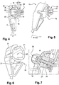
- FIG 4 there is shown an attachment assembly according to the invention, in section, having a nozzle 15 and a base 16 in an assembly position.
- the base 16 has a head 17 in the form of a solid spherical cap capable of cooperating with the tip 15.
- the cap 17 has a height H and a determined radius R: the height H of the head 17 being greater than its radius R.
- the base of the spherical cap 17 delimits with the attachment interface 18 of the base 16, in the form of a flange, a groove 19 of determined width l.
- This groove 19 can be advantageously used to insert a loop such as the loop 5 of the figure 3 .
- the base 16 can serve both for a clipper tip 15 for a loop to thread 5.
- the periphery of the collar is advantageously chamfered to allow self centering of the loop 5 inside the groove 19 ; the base 16 by its general form can be likened to a "diabolo".
- the tip 15 has a hollow spherical cap 20 forming a cavity 20 adapted to receive a portion of the head 17 of the base 16.
- the depth P of the cavity 20 is greater than its radius R.
- the rays R of the cavity 20 and the head 17 are identical.
- the depth P of the cavity 20 is between the radius R height H of the head 17 (R ⁇ P ⁇ H).
- the wall or edge of the nozzle 15 delimiting the cavity 20 is shaped to have three lugs 21 distributed facing each other at 180 ° C. one of the others and which are capable of deforming during the introduction of the tip 15 on the base 16.
- the controlled elastic deformation of the tabs 21, allows sufficient pressure to maintain the ball-type connection between the tip 15 and the base 16.
- the fixing assembly as described above allows a wide variety of possible configurations in the positioning of the base 16 on different types of flaps 6 as well as metal or plastic or composite material, with deflections of the flap 6 and of the tablet 1 for which the tip 15 can accept a maximum offset angle ⁇ max of 20 ° on all degrees of freedom offered by the ball-type connection with the base 16.
- the attachment interface 18 of the base comprises anchoring means 22 able to fix the base 16 on a support such as the interior lining 8 of the flap 6.
- the anchoring means 22 as illustrated comprise three or four tabs or fastening clips 23 integral with the body of the base 16 and cooperating with openings (not shown) in the packing 8.
- the body of the base 16 is traversed along its longitudinal axis by a bore 24 adapted to receive a screw 25.
- the head 17 of the base 16 has a recess 26 centered on the same longitudinal axis and adapted to receive the head of the screw 25 which is embedded in the recess 26.
- the threaded portion of the screw 25 passes right through the body of the base 16, the gasket 8 and a portion of the flap 6.
- the screw head 25 abuts in the recess 26.
- the end of the threaded portion opposed to the screw head, protruding from the portion of the flap 6, is adapted to receive a nut (not shown) so as to ensure the clamping of the stack constituted by the body of the base 16 and the trim portion 8 interposed between the flap 6 and the base 16, and therefore the secure attachment of the base 16 on the flap 6 preventing tearing of the base 16 of the lining 8 at the time of unclipping the tip 15 of the head 17 of the base 16.
- the nut may be replaced by a threaded boss (not shown), for example integral with the material of the flap 6 or attached to the material of the flap 6.
- the flexible cord 2 can be extensible or inextensible longitudinally but the fixing assembly according to the invention makes it possible to keep the cord 2 taut at the beginning and the end of the kinematics of the flap 6.
Landscapes
- Engineering & Computer Science (AREA)
- Mechanical Engineering (AREA)
- Vehicle Step Arrangements And Article Storage (AREA)
- Vehicle Interior And Exterior Ornaments, Soundproofing, And Insulation (AREA)
- Fittings On The Vehicle Exterior For Carrying Loads, And Devices For Holding Or Mounting Articles (AREA)
- Power-Operated Mechanisms For Wings (AREA)
Claims (8)
- Befestigungsanordnung eines Aufklappbegrenzers einer hinteren Ablage (1) eines Kraftfahrzeugs auf einem Sockel (16), der fest mit der Heckklappe (6) des Fahrzeugs verbunden ist, wobei der Begrenzer mit mindestens einer Kordel (2) versehen ist, von der ein erstes Ende (3) fest mit einer hinteren Ablage (1) verbunden ist, und von der ein zweites Ende (4) mit einem ersten Befestigungselement (5; 15) versehen ist, das geeignet ist, abnehmbar auf dem Sockel (16), der fest mit der Klappe (2) verbunden ist, befestigt zu sein, wobei der Körper des Sockels (16) einen Kopf (17) umfasst, der eine massive sphärische Haube bildet, die geeignet ist, das erste Befestigungselement (5; 15) aufzunehmen, und eine Befestigungsschnittfläche (18), die geeignet ist, um den Sockel (16) fest auf der Klappe (6) zu verbinden, dadurch gekennzeichnet, dass das erste Befestigungselement ein Ansatz (15) ist, der geeignet ist, auf dem Kopf (17) des Sockels (16) geclipst zu sein, und dass der Ansatz (15) einen Hohlraum (20) umfasst, der eine hohle sphärische Haube mit demselben Radius (R) wie die massive sphärische Haube (17) des Sockels (16) bildet; wobei die Tiefe (P) des Hohlraums (20) größer ist als sein Radius (R) und die Tiefe (P) des Hohlraums (20) zwischen dem Radius (R) und der Höhe (H) der massiven sphärischen Haube (17) liegt.
- Befestigungsanordnung nach Anspruch 1, dadurch gekennzeichnet, dass die Haube (17) eine bestimmte Höhe (H) und einen bestimmten Radius (R) aufweist; wobei die Höhe (H) der Haube (17) größer ist als ihr Radius (R).
- Befestigungsanordnung nach einem der vorstehenden Ansprüche, dadurch gekennzeichnet, dass die Befestigungsschnittfläche (18) mit dem Kopf (17) des Sockels (16) eine Nut (19) mit bestimmter Breite (l) abgrenzt, die geeignet ist, das erste Befestigungselement (5) aufzunehmen.
- Befestigungsanordnung nach dem vorstehenden Anspruch, dadurch gekennzeichnet, dass das erste Befestigungselement eine Schleife (5) ist, die angepasst ist, um zwischen dem Kopf (16) und der Befestigungsschnittfläche (18) des Sockels (16) in dem Inneren der Nut (19) aufgezogen zu werden.
- Befestigungsanordnung nach dem vorstehenden Anspruch, dadurch gekennzeichnet, dass die Befestigungsschnittfläche (18) einen Flansch definiert, der eine Abfasung umfasst, die zu der Nut (19) ausgerichtet ist, die das Zentrieren der Schleife (5) in der Nut (19) sicherstellt.
- Befestigungsanordnung nach einem der vorstehenden Ansprüche, dadurch gekennzeichnet, dass der Hohlraum (20) von einem umfänglichen Rand mit bestimmter Stärke abgegrenzt ist, der aus mindestens zwei elastisch verformbaren Pratzen (21) gebildet ist, die einander gegenüberliegend angeordnet sind.
- Befestigungsanordnung nach einem der vorstehenden Ansprüche, dadurch gekennzeichnet, dass der maximale Versatzwinkel (θmax) des Ansatzes (15) auf dem Sockel (16) kleiner oder gleich 20° zwischen zwei Endpositionen des Ansatzes (15) auf dem Sockel (16) ist.
- Befestigungsanordnung nach einem der vorstehenden Ansprüche, wobei die Heckklappe (6) eine innere Verkleidung (8) umfasst, Anordnung dadurch gekennzeichnet, dass der Sockel (16) fest auf der Klappe (6) mittels einer Schraube (25) verbunden ist, die den Körper des Sockels (16) und den Verkleidungsteil (8) der Heckklappe (6) vollständig durchquert; wobei die Schraube (25) den Körper des Sockels (16) und den Verkleidungsteil (8) auf der Klappe (6) hält.
Applications Claiming Priority (1)
| Application Number | Priority Date | Filing Date | Title |
|---|---|---|---|
| FR1660065A FR3057510A1 (fr) | 2016-10-18 | 2016-10-18 | Ensemble de fixation d'un limiteur de debattement d'une tablette arriere sur le volet arriere d'un vehicule automobile |
Publications (2)
| Publication Number | Publication Date |
|---|---|
| EP3312053A1 EP3312053A1 (de) | 2018-04-25 |
| EP3312053B1 true EP3312053B1 (de) | 2019-04-03 |
Family
ID=58213174
Family Applications (1)
| Application Number | Title | Priority Date | Filing Date |
|---|---|---|---|
| EP17191954.1A Active EP3312053B1 (de) | 2016-10-18 | 2017-09-19 | Befestigungsanordnung für aufklappbegrenzung einer hinteren ablage auf der heckklappe eines kraftfahrzeugs |
Country Status (3)
| Country | Link |
|---|---|
| EP (1) | EP3312053B1 (de) |
| CN (1) | CN107953833B (de) |
| FR (1) | FR3057510A1 (de) |
Families Citing this family (1)
| Publication number | Priority date | Publication date | Assignee | Title |
|---|---|---|---|---|
| ES2769915A1 (es) * | 2018-12-28 | 2020-06-29 | Seat Sa | Sistema de fijacion de una bandeja de maletero, y vehiculo automovil provisto de una bandeja de maletero que comprende dicho sistema de fijacion |
Family Cites Families (12)
| Publication number | Priority date | Publication date | Assignee | Title |
|---|---|---|---|---|
| FR2256654A5 (de) * | 1973-12-28 | 1975-07-25 | Peugeot & Renault | |
| JPH02114213U (de) * | 1989-03-01 | 1990-09-12 | ||
| DE19605406A1 (de) * | 1996-02-14 | 1997-08-21 | Reum Ag | Aufrollvorrichtung zum wegverzögernden Anheben der Hutablage von Fahrzeugen |
| DE19652912A1 (de) * | 1996-12-19 | 1998-07-02 | Boellhoff Gmbh Verbindungs Und | Haltebandstraffer |
| DE102004008874A1 (de) * | 2004-02-18 | 2005-09-08 | Bos Gmbh & Co. Kg | Funktionseinheit für einen Fahrzeuginnenraum |
| JP4383205B2 (ja) * | 2004-02-26 | 2009-12-16 | 株式会社小糸製作所 | ユニバーサルジョイント構成体、および、車両用灯具 |
| US7469955B2 (en) * | 2007-05-29 | 2008-12-30 | Gm Global Technology Operations, Inc. | Rotatably-mountable bumper and method for cushioning contact between a vehicle hood and grill |
| JP4690374B2 (ja) * | 2007-09-24 | 2011-06-01 | 本田技研工業株式会社 | カーゴフロアボックス |
| JP2009293685A (ja) * | 2008-06-04 | 2009-12-17 | Sato Yoshinori | ボールハウジング、ボールジョイント及びボールハウジングからのボールスタッドの取外し方法 |
| FR2944492B1 (fr) * | 2009-04-16 | 2011-04-01 | Renault Sas | Tablette de coffre de vehicule pourvue d'un dispositif d'eclairage et vehicule ainsi equipe |
| DE202009004736U1 (de) * | 2009-04-24 | 2009-07-09 | Jordan Spritzgußtechnik GmbH | Flexibles Zugkraftübertragungselement für eine Ablage |
| FR3009528B1 (fr) * | 2013-08-06 | 2015-08-14 | Renault Sa | Tablette pour coffre de vehicule automobile |
-
2016
- 2016-10-18 FR FR1660065A patent/FR3057510A1/fr not_active Withdrawn
-
2017
- 2017-09-19 EP EP17191954.1A patent/EP3312053B1/de active Active
- 2017-10-18 CN CN201710973820.2A patent/CN107953833B/zh active Active
Non-Patent Citations (1)
| Title |
|---|
| None * |
Also Published As
| Publication number | Publication date |
|---|---|
| CN107953833B (zh) | 2022-12-09 |
| EP3312053A1 (de) | 2018-04-25 |
| CN107953833A (zh) | 2018-04-24 |
| FR3057510A1 (fr) | 2018-04-20 |
Similar Documents
| Publication | Publication Date | Title |
|---|---|---|
| EP3374647B1 (de) | Element zur positionierung einer komponente im raum | |
| WO2008047035A2 (fr) | Dispositif de distribution de produit fluide | |
| FR2938025A1 (fr) | Agrafe pour la fixation d'un equipement sur une structure | |
| EP3546685A1 (de) | Justiervorrichtung zum anheben eines werkstücks | |
| FR3002574A1 (fr) | Butee a hauteur auto-reglable pour un ouvrant de vehicule automobile et procede pour regler une telle butee | |
| FR2786845A1 (fr) | Attache de fixation notamment pour cables, tuyauteries ou analogues | |
| EP3312053B1 (de) | Befestigungsanordnung für aufklappbegrenzung einer hinteren ablage auf der heckklappe eines kraftfahrzeugs | |
| EP1906031B1 (de) | Universalbefestigungstecker und Befestigungseinheit, die einen solchen Stecker umfasst | |
| EP2730487B1 (de) | Haltebauteil für zwei gegeneinander befestigte Karosserieelemente eines Kraftfahrzeugs | |
| CA2515573A1 (fr) | Dispositif de fixation a pince | |
| EP1138963A1 (de) | Haltevorrichtung für eine Bowdenzughülle | |
| FR2796427A1 (fr) | Dispositif de premontage d'un ecrou pour ensemble de fixation du type vis-ecrou | |
| FR2949429A1 (fr) | Manchon de protection pour vehicule en particulier pour vehicule de type motocyclette | |
| FR2739816A1 (fr) | Projecteur pour vehicules | |
| EP3861216B1 (de) | Vorrichtung zum halten eines verschlusses einer öffnung, die in einer wand eines karosserieteils geformt ist | |
| FR2954428A1 (fr) | Dispositif limiteur de couple et bouchon pour tete de tubulure comportant un tel dispositif | |
| FR2766864A1 (fr) | Dispositif de condamnation d'un ouvrant de vehicule automobile | |
| FR2948982A1 (fr) | Dispositif de pre-maintien d'une vis sur une premiere piece destinee a etre fixee sur une seconde piece au moyen de ladite vis | |
| FR2935031A1 (fr) | Dispositif pour fixer ensemble deux pieces, en une seule operation | |
| FR2689945A1 (fr) | Structure à double parois, obturable par un bouchon formant guide pour un organe quelconque à monter à l'intérieur de cette structure. | |
| FR2990010A1 (fr) | Organe de fixation d'un accessoire sur un support ainsi que du support sur une structure | |
| EP3697997B1 (de) | Vorrichtung zur abstandsherstellung von einem öffnungselement zu einem stationären element, insbesondere zu einem kraftfahrzeug | |
| FR2935873A1 (fr) | Organe de solidarisation reversible de deux sangles entre elles. | |
| FR2901584A1 (fr) | Manchon de maintien d'un element d'appui ou de couverture sous le plancher de l'habitacle d'un vehicule automobile | |
| FR2923758A1 (fr) | Cloison anti-recyclage d'air pour vehicule automobile et vehicule automobile equipe d'une telle cloison. |
Legal Events
| Date | Code | Title | Description |
|---|---|---|---|
| PUAI | Public reference made under article 153(3) epc to a published international application that has entered the european phase |
Free format text: ORIGINAL CODE: 0009012 |
|
| STAA | Information on the status of an ep patent application or granted ep patent |
Free format text: STATUS: THE APPLICATION HAS BEEN PUBLISHED |
|
| AK | Designated contracting states |
Kind code of ref document: A1 Designated state(s): AL AT BE BG CH CY CZ DE DK EE ES FI FR GB GR HR HU IE IS IT LI LT LU LV MC MK MT NL NO PL PT RO RS SE SI SK SM TR |
|
| AX | Request for extension of the european patent |
Extension state: BA ME |
|
| STAA | Information on the status of an ep patent application or granted ep patent |
Free format text: STATUS: REQUEST FOR EXAMINATION WAS MADE |
|
| 17P | Request for examination filed |
Effective date: 20180918 |
|
| RBV | Designated contracting states (corrected) |
Designated state(s): AL AT BE BG CH CY CZ DE DK EE ES FI FR GB GR HR HU IE IS IT LI LT LU LV MC MK MT NL NO PL PT RO RS SE SI SK SM TR |
|
| GRAP | Despatch of communication of intention to grant a patent |
Free format text: ORIGINAL CODE: EPIDOSNIGR1 |
|
| STAA | Information on the status of an ep patent application or granted ep patent |
Free format text: STATUS: GRANT OF PATENT IS INTENDED |
|
| RIC1 | Information provided on ipc code assigned before grant |
Ipc: B60R 5/04 20060101AFI20181001BHEP |
|
| INTG | Intention to grant announced |
Effective date: 20181026 |
|
| GRAS | Grant fee paid |
Free format text: ORIGINAL CODE: EPIDOSNIGR3 |
|
| GRAA | (expected) grant |
Free format text: ORIGINAL CODE: 0009210 |
|
| STAA | Information on the status of an ep patent application or granted ep patent |
Free format text: STATUS: THE PATENT HAS BEEN GRANTED |
|
| AK | Designated contracting states |
Kind code of ref document: B1 Designated state(s): AL AT BE BG CH CY CZ DE DK EE ES FI FR GB GR HR HU IE IS IT LI LT LU LV MC MK MT NL NO PL PT RO RS SE SI SK SM TR |
|
| REG | Reference to a national code |
Ref country code: GB Ref legal event code: FG4D Free format text: NOT ENGLISH |
|
| REG | Reference to a national code |
Ref country code: CH Ref legal event code: EP Ref country code: AT Ref legal event code: REF Ref document number: 1115327 Country of ref document: AT Kind code of ref document: T Effective date: 20190415 |
|
| REG | Reference to a national code |
Ref country code: DE Ref legal event code: R096 Ref document number: 602017003068 Country of ref document: DE |
|
| REG | Reference to a national code |
Ref country code: IE Ref legal event code: FG4D Free format text: LANGUAGE OF EP DOCUMENT: FRENCH |
|
| REG | Reference to a national code |
Ref country code: DE Ref legal event code: R084 Ref document number: 602017003068 Country of ref document: DE |
|
| REG | Reference to a national code |
Ref country code: GB Ref legal event code: 746 Effective date: 20190617 |
|
| REG | Reference to a national code |
Ref country code: NL Ref legal event code: MP Effective date: 20190403 |
|
| REG | Reference to a national code |
Ref country code: LT Ref legal event code: MG4D |
|
| REG | Reference to a national code |
Ref country code: AT Ref legal event code: MK05 Ref document number: 1115327 Country of ref document: AT Kind code of ref document: T Effective date: 20190403 |
|
| PG25 | Lapsed in a contracting state [announced via postgrant information from national office to epo] |
Ref country code: NL Free format text: LAPSE BECAUSE OF FAILURE TO SUBMIT A TRANSLATION OF THE DESCRIPTION OR TO PAY THE FEE WITHIN THE PRESCRIBED TIME-LIMIT Effective date: 20190403 |
|
| PG25 | Lapsed in a contracting state [announced via postgrant information from national office to epo] |
Ref country code: FI Free format text: LAPSE BECAUSE OF FAILURE TO SUBMIT A TRANSLATION OF THE DESCRIPTION OR TO PAY THE FEE WITHIN THE PRESCRIBED TIME-LIMIT Effective date: 20190403 Ref country code: CZ Free format text: LAPSE BECAUSE OF FAILURE TO SUBMIT A TRANSLATION OF THE DESCRIPTION OR TO PAY THE FEE WITHIN THE PRESCRIBED TIME-LIMIT Effective date: 20190403 Ref country code: NO Free format text: LAPSE BECAUSE OF FAILURE TO SUBMIT A TRANSLATION OF THE DESCRIPTION OR TO PAY THE FEE WITHIN THE PRESCRIBED TIME-LIMIT Effective date: 20190703 Ref country code: LT Free format text: LAPSE BECAUSE OF FAILURE TO SUBMIT A TRANSLATION OF THE DESCRIPTION OR TO PAY THE FEE WITHIN THE PRESCRIBED TIME-LIMIT Effective date: 20190403 Ref country code: HR Free format text: LAPSE BECAUSE OF FAILURE TO SUBMIT A TRANSLATION OF THE DESCRIPTION OR TO PAY THE FEE WITHIN THE PRESCRIBED TIME-LIMIT Effective date: 20190403 Ref country code: ES Free format text: LAPSE BECAUSE OF FAILURE TO SUBMIT A TRANSLATION OF THE DESCRIPTION OR TO PAY THE FEE WITHIN THE PRESCRIBED TIME-LIMIT Effective date: 20190403 Ref country code: AL Free format text: LAPSE BECAUSE OF FAILURE TO SUBMIT A TRANSLATION OF THE DESCRIPTION OR TO PAY THE FEE WITHIN THE PRESCRIBED TIME-LIMIT Effective date: 20190403 Ref country code: PT Free format text: LAPSE BECAUSE OF FAILURE TO SUBMIT A TRANSLATION OF THE DESCRIPTION OR TO PAY THE FEE WITHIN THE PRESCRIBED TIME-LIMIT Effective date: 20190803 Ref country code: SE Free format text: LAPSE BECAUSE OF FAILURE TO SUBMIT A TRANSLATION OF THE DESCRIPTION OR TO PAY THE FEE WITHIN THE PRESCRIBED TIME-LIMIT Effective date: 20190403 |
|
| PG25 | Lapsed in a contracting state [announced via postgrant information from national office to epo] |
Ref country code: LV Free format text: LAPSE BECAUSE OF FAILURE TO SUBMIT A TRANSLATION OF THE DESCRIPTION OR TO PAY THE FEE WITHIN THE PRESCRIBED TIME-LIMIT Effective date: 20190403 Ref country code: BG Free format text: LAPSE BECAUSE OF FAILURE TO SUBMIT A TRANSLATION OF THE DESCRIPTION OR TO PAY THE FEE WITHIN THE PRESCRIBED TIME-LIMIT Effective date: 20190703 Ref country code: RS Free format text: LAPSE BECAUSE OF FAILURE TO SUBMIT A TRANSLATION OF THE DESCRIPTION OR TO PAY THE FEE WITHIN THE PRESCRIBED TIME-LIMIT Effective date: 20190403 Ref country code: GR Free format text: LAPSE BECAUSE OF FAILURE TO SUBMIT A TRANSLATION OF THE DESCRIPTION OR TO PAY THE FEE WITHIN THE PRESCRIBED TIME-LIMIT Effective date: 20190704 Ref country code: PL Free format text: LAPSE BECAUSE OF FAILURE TO SUBMIT A TRANSLATION OF THE DESCRIPTION OR TO PAY THE FEE WITHIN THE PRESCRIBED TIME-LIMIT Effective date: 20190403 |
|
| PG25 | Lapsed in a contracting state [announced via postgrant information from national office to epo] |
Ref country code: IS Free format text: LAPSE BECAUSE OF FAILURE TO SUBMIT A TRANSLATION OF THE DESCRIPTION OR TO PAY THE FEE WITHIN THE PRESCRIBED TIME-LIMIT Effective date: 20190803 Ref country code: AT Free format text: LAPSE BECAUSE OF FAILURE TO SUBMIT A TRANSLATION OF THE DESCRIPTION OR TO PAY THE FEE WITHIN THE PRESCRIBED TIME-LIMIT Effective date: 20190403 |
|
| REG | Reference to a national code |
Ref country code: DE Ref legal event code: R097 Ref document number: 602017003068 Country of ref document: DE |
|
| PG25 | Lapsed in a contracting state [announced via postgrant information from national office to epo] |
Ref country code: RO Free format text: LAPSE BECAUSE OF FAILURE TO SUBMIT A TRANSLATION OF THE DESCRIPTION OR TO PAY THE FEE WITHIN THE PRESCRIBED TIME-LIMIT Effective date: 20190403 Ref country code: SK Free format text: LAPSE BECAUSE OF FAILURE TO SUBMIT A TRANSLATION OF THE DESCRIPTION OR TO PAY THE FEE WITHIN THE PRESCRIBED TIME-LIMIT Effective date: 20190403 Ref country code: DK Free format text: LAPSE BECAUSE OF FAILURE TO SUBMIT A TRANSLATION OF THE DESCRIPTION OR TO PAY THE FEE WITHIN THE PRESCRIBED TIME-LIMIT Effective date: 20190403 Ref country code: EE Free format text: LAPSE BECAUSE OF FAILURE TO SUBMIT A TRANSLATION OF THE DESCRIPTION OR TO PAY THE FEE WITHIN THE PRESCRIBED TIME-LIMIT Effective date: 20190403 |
|
| PLBE | No opposition filed within time limit |
Free format text: ORIGINAL CODE: 0009261 |
|
| STAA | Information on the status of an ep patent application or granted ep patent |
Free format text: STATUS: NO OPPOSITION FILED WITHIN TIME LIMIT |
|
| PG25 | Lapsed in a contracting state [announced via postgrant information from national office to epo] |
Ref country code: IT Free format text: LAPSE BECAUSE OF FAILURE TO SUBMIT A TRANSLATION OF THE DESCRIPTION OR TO PAY THE FEE WITHIN THE PRESCRIBED TIME-LIMIT Effective date: 20190403 Ref country code: SM Free format text: LAPSE BECAUSE OF FAILURE TO SUBMIT A TRANSLATION OF THE DESCRIPTION OR TO PAY THE FEE WITHIN THE PRESCRIBED TIME-LIMIT Effective date: 20190403 |
|
| 26N | No opposition filed |
Effective date: 20200106 |
|
| PG25 | Lapsed in a contracting state [announced via postgrant information from national office to epo] |
Ref country code: TR Free format text: LAPSE BECAUSE OF FAILURE TO SUBMIT A TRANSLATION OF THE DESCRIPTION OR TO PAY THE FEE WITHIN THE PRESCRIBED TIME-LIMIT Effective date: 20190403 |
|
| PG25 | Lapsed in a contracting state [announced via postgrant information from national office to epo] |
Ref country code: SI Free format text: LAPSE BECAUSE OF FAILURE TO SUBMIT A TRANSLATION OF THE DESCRIPTION OR TO PAY THE FEE WITHIN THE PRESCRIBED TIME-LIMIT Effective date: 20190403 Ref country code: MC Free format text: LAPSE BECAUSE OF FAILURE TO SUBMIT A TRANSLATION OF THE DESCRIPTION OR TO PAY THE FEE WITHIN THE PRESCRIBED TIME-LIMIT Effective date: 20190403 |
|
| PG25 | Lapsed in a contracting state [announced via postgrant information from national office to epo] |
Ref country code: IE Free format text: LAPSE BECAUSE OF NON-PAYMENT OF DUE FEES Effective date: 20190919 Ref country code: LU Free format text: LAPSE BECAUSE OF NON-PAYMENT OF DUE FEES Effective date: 20190919 |
|
| REG | Reference to a national code |
Ref country code: BE Ref legal event code: MM Effective date: 20190930 |
|
| PG25 | Lapsed in a contracting state [announced via postgrant information from national office to epo] |
Ref country code: BE Free format text: LAPSE BECAUSE OF NON-PAYMENT OF DUE FEES Effective date: 20190930 |
|
| REG | Reference to a national code |
Ref country code: CH Ref legal event code: PL |
|
| PG25 | Lapsed in a contracting state [announced via postgrant information from national office to epo] |
Ref country code: CY Free format text: LAPSE BECAUSE OF FAILURE TO SUBMIT A TRANSLATION OF THE DESCRIPTION OR TO PAY THE FEE WITHIN THE PRESCRIBED TIME-LIMIT Effective date: 20190403 |
|
| PG25 | Lapsed in a contracting state [announced via postgrant information from national office to epo] |
Ref country code: HU Free format text: LAPSE BECAUSE OF FAILURE TO SUBMIT A TRANSLATION OF THE DESCRIPTION OR TO PAY THE FEE WITHIN THE PRESCRIBED TIME-LIMIT; INVALID AB INITIO Effective date: 20170919 Ref country code: MT Free format text: LAPSE BECAUSE OF FAILURE TO SUBMIT A TRANSLATION OF THE DESCRIPTION OR TO PAY THE FEE WITHIN THE PRESCRIBED TIME-LIMIT Effective date: 20190403 |
|
| PG25 | Lapsed in a contracting state [announced via postgrant information from national office to epo] |
Ref country code: LI Free format text: LAPSE BECAUSE OF NON-PAYMENT OF DUE FEES Effective date: 20200930 Ref country code: CH Free format text: LAPSE BECAUSE OF NON-PAYMENT OF DUE FEES Effective date: 20200930 |
|
| PG25 | Lapsed in a contracting state [announced via postgrant information from national office to epo] |
Ref country code: MK Free format text: LAPSE BECAUSE OF FAILURE TO SUBMIT A TRANSLATION OF THE DESCRIPTION OR TO PAY THE FEE WITHIN THE PRESCRIBED TIME-LIMIT Effective date: 20190403 |
|
| REG | Reference to a national code |
Ref country code: DE Ref legal event code: R081 Ref document number: 602017003068 Country of ref document: DE Owner name: STELLANTIS AUTO SAS, FR Free format text: FORMER OWNER: PSA AUTOMOBILES SA, POISSY, FR |
|
| PGFP | Annual fee paid to national office [announced via postgrant information from national office to epo] |
Ref country code: GB Payment date: 20240820 Year of fee payment: 8 |
|
| PGFP | Annual fee paid to national office [announced via postgrant information from national office to epo] |
Ref country code: DE Payment date: 20250820 Year of fee payment: 9 |
|
| PGFP | Annual fee paid to national office [announced via postgrant information from national office to epo] |
Ref country code: FR Payment date: 20250820 Year of fee payment: 9 |