EP3374681B1 - Bagues d'étanchéité et ensembles de bagues d'étanchéité pour applications finales à haute température - Google Patents
Bagues d'étanchéité et ensembles de bagues d'étanchéité pour applications finales à haute température Download PDFInfo
- Publication number
- EP3374681B1 EP3374681B1 EP16865004.2A EP16865004A EP3374681B1 EP 3374681 B1 EP3374681 B1 EP 3374681B1 EP 16865004 A EP16865004 A EP 16865004A EP 3374681 B1 EP3374681 B1 EP 3374681B1
- Authority
- EP
- European Patent Office
- Prior art keywords
- ring
- sealing
- sealing assembly
- outer ring
- center
- Prior art date
- Legal status (The legal status is an assumption and is not a legal conclusion. Google has not performed a legal analysis and makes no representation as to the accuracy of the status listed.)
- Active
Links
Images








Classifications
-
- F—MECHANICAL ENGINEERING; LIGHTING; HEATING; WEAPONS; BLASTING
- F16—ENGINEERING ELEMENTS AND UNITS; GENERAL MEASURES FOR PRODUCING AND MAINTAINING EFFECTIVE FUNCTIONING OF MACHINES OR INSTALLATIONS; THERMAL INSULATION IN GENERAL
- F16L—PIPES; JOINTS OR FITTINGS FOR PIPES; SUPPORTS FOR PIPES, CABLES OR PROTECTIVE TUBING; MEANS FOR THERMAL INSULATION IN GENERAL
- F16L23/00—Flanged joints
- F16L23/16—Flanged joints characterised by the sealing means
- F16L23/18—Flanged joints characterised by the sealing means the sealing means being rings
- F16L23/20—Flanged joints characterised by the sealing means the sealing means being rings made exclusively of metal
-
- F—MECHANICAL ENGINEERING; LIGHTING; HEATING; WEAPONS; BLASTING
- F16—ENGINEERING ELEMENTS AND UNITS; GENERAL MEASURES FOR PRODUCING AND MAINTAINING EFFECTIVE FUNCTIONING OF MACHINES OR INSTALLATIONS; THERMAL INSULATION IN GENERAL
- F16L—PIPES; JOINTS OR FITTINGS FOR PIPES; SUPPORTS FOR PIPES, CABLES OR PROTECTIVE TUBING; MEANS FOR THERMAL INSULATION IN GENERAL
- F16L17/00—Joints with packing adapted to sealing by fluid pressure
- F16L17/06—Joints with packing adapted to sealing by fluid pressure with sealing rings arranged between the end surfaces of the pipes or flanges or arranged in recesses in the pipe ends or flanges
-
- F—MECHANICAL ENGINEERING; LIGHTING; HEATING; WEAPONS; BLASTING
- F16—ENGINEERING ELEMENTS AND UNITS; GENERAL MEASURES FOR PRODUCING AND MAINTAINING EFFECTIVE FUNCTIONING OF MACHINES OR INSTALLATIONS; THERMAL INSULATION IN GENERAL
- F16L—PIPES; JOINTS OR FITTINGS FOR PIPES; SUPPORTS FOR PIPES, CABLES OR PROTECTIVE TUBING; MEANS FOR THERMAL INSULATION IN GENERAL
- F16L23/00—Flanged joints
- F16L23/04—Flanged joints the flanges being connected by members tensioned in the radial plane
-
- F—MECHANICAL ENGINEERING; LIGHTING; HEATING; WEAPONS; BLASTING
- F16—ENGINEERING ELEMENTS AND UNITS; GENERAL MEASURES FOR PRODUCING AND MAINTAINING EFFECTIVE FUNCTIONING OF MACHINES OR INSTALLATIONS; THERMAL INSULATION IN GENERAL
- F16L—PIPES; JOINTS OR FITTINGS FOR PIPES; SUPPORTS FOR PIPES, CABLES OR PROTECTIVE TUBING; MEANS FOR THERMAL INSULATION IN GENERAL
- F16L23/00—Flanged joints
- F16L23/16—Flanged joints characterised by the sealing means
- F16L23/18—Flanged joints characterised by the sealing means the sealing means being rings
-
- F—MECHANICAL ENGINEERING; LIGHTING; HEATING; WEAPONS; BLASTING
- F16—ENGINEERING ELEMENTS AND UNITS; GENERAL MEASURES FOR PRODUCING AND MAINTAINING EFFECTIVE FUNCTIONING OF MACHINES OR INSTALLATIONS; THERMAL INSULATION IN GENERAL
- F16L—PIPES; JOINTS OR FITTINGS FOR PIPES; SUPPORTS FOR PIPES, CABLES OR PROTECTIVE TUBING; MEANS FOR THERMAL INSULATION IN GENERAL
- F16L23/00—Flanged joints
- F16L23/16—Flanged joints characterised by the sealing means
- F16L23/18—Flanged joints characterised by the sealing means the sealing means being rings
- F16L23/22—Flanged joints characterised by the sealing means the sealing means being rings made exclusively of a material other than metal
Definitions
- This invention relates to the field of sealing assemblies having sealing rings within the assembly, and the sealing rings for use in such assemblies, particularly to those which are useful in semiconductor manufacturing applications, and more particularly to those that are useful in "subfab" areas including for use as vacuum and pressure sealing assemblies including vacuum sealing rings.
- Sealing assemblies are known for various end applications, for example, for use in sealing joined parts, such as doors, gates, pipes, portals, vents, and similar joining or reversibly mating parts.
- Sealing assemblies typically incorporate one or more sealing rings and are employed in various industries, such as the fluid handling, aerospace and semiconductor areas. In the semiconductor areas, there are sealing assemblies for doors and gates between various reaction chambers in semiconductor processing equipment in the microchip manufacturing area.
- seals for use in various assemblies employed in the manufacturing support systems, for example in a "subfab" environment, such as incoming delivery conduit for reactants, air handling conduit and exhaust vacuum system piping.
- sealing assemblies and their associated sealing rings need to meet various standards.
- typical designs may be found as described in German Standard, DIN 28404 (1981) and/or in International Standard ISO 2861 (2013) and International Standard ISO 1206 (1986).
- a standard vacuum seal as in ISO 2861 is shown having an O-ring 1, two vacuum couplings or fittings 2, an O-ring carrier or centering ring 3, and clamps 4.
- Such typical sealing configurations as shown in Fig. 1 are suitable for most applications with use temperatures from room temperature up to about 100°C. Beyond 100°C, typical prior art designs can result in damage to the seals, and potential failure. Further, there is also typically insufficient space in such assemblies for thermal expansion at higher temperatures.
- Fig. 1 Prior art sealing assemblies are guided by various existing industry specifications, including ISO 2861:2013; ISO 1609:1986; DIN 28404:1986; DIN 28403: 1986 and PNEUROP 6606: 1981.
- Such designs describe assemblies as shown, for example, in Fig. 1 .
- Such designs use a T-shaped metal centering ring (o-ring support) as a ring on the inner diameter of the elastomeric sealing ring for use in internal vacuum applications. These designs generally allow room for expansion of the seal at temperatures over about 180°C, but do not allow for internal pressure conditions.
- Other designs as shown in Fig. 1a have a metal centering ring (o-ring support), overpressure rings and an elastomeric seal. Such designs generally have insufficient space for thermal expansion of the seal.
- the present applicant has a double-lobed seal to improve sealing capability at higher temperatures and having only an inner ring (Greene, Tweed Seal No. 5641-0736-SC513). Such assemblies are an improvement but the seal is still left exposed and there can still be impacts from thermal expansion.
- U.S. Patent No. 6,286,839 shows a vacuum sealing ring having an inner, compressible metal ring that is clamped upon installation in an apparatus.
- the inner, metal ring has a sideways and outwardly facing, U-shaped cross-sectional profile.
- the metal ring surrounds an outer elastomeric sealing O-ring having a circular cross-section.
- the sealing O-ring is compressed within the metal ring in use.
- the design does not have an outer ring on an exterior of the O-ring.
- the inner metal ring is shaped to seal the interior space from particulation from the elastomeric O-ring seal.
- a similar design having an outer seal shaped to complement the interior of the sideways U-shaped inner ring is shown in U.S. Patent No. 6,357,759 .
- the outer elastomer sealing material filling the interior of the inner metal ring curves outwardly.
- U.S. Patent No. 7,159,906 teaches a metal and/or elastomer ring for a vacuum sealing assembly including vacuum flanges having V-notched receiving areas.
- the metal flange rings are also shaped on more of a V-shaped exterior surface which angles to a flat outer-facing surface.
- the modified V-angled portions engage V-notched receiving areas within the flanges.
- the flange lips compress to give the desired seal against the interior sealing ring.
- U.S. Patent No. 6,325,390 shows a vacuum sealing assembly having a centering ring with a circumferential flange (O-ring support) for receiving an O-ring with a circular cross-sectional profile.
- the centering ring has upper and lower beveled surfaces on its exterior to seat within mating surfaces in the upper and lower vacuum fittings.
- a clamping ring is used to compress the elastomer.
- U.S. Patent No. 5,722,668 discloses a vacuum sealing assembly incorporating two elastomeric seals, one of which comprises a thermoplastic sacrificial protective collar surrounding the seal.
- the outer collar may be formed of polyetherether ketone (PEEK), polytetrafluoroethlene (PTFE), polyether sulfone (PES) or polyimide (PI), while the inner seal is formed of a fluoroelastomer.
- PEEK polyetherether ketone
- PTFE polytetrafluoroethlene
- PES polyether sulfone
- PI polyimide
- the assembly collar has two fingers that surround a portion of the outer surface of the O-ring seal and also help to seal the space in which the assembly is situated.
- the design is to provide a shielding effect on one side of the elastomer O-ring seal.
- U.S. Patent No. 6,932,354 teaches a semiconductor manufacturing chamber gate door that incorporates a seal having a cross-sectional view which has a generally parabolic cross-sectional design.
- Korean Patent Publication No. KR 2014-073081A shows a seal for a vacuum assembly having a dovetail groove.
- the embodiments show modified seals having a more "barrel" shape as well.
- Korean Patent No. KR 1-471772 B1 of M & EE Technology Co., Ltd. teaches a bonded seal. It has a metallic portion bonded to a perfluoroelastomer (FFKM) seal.
- the inner and outer rings 100a, 100b are almost a sideways pyramidal shape and are formed of FFKM.
- the connecting piece that spans between the two rings is formed of a fluorinated resin.
- EP 1096183 A2 and US 3,704,021 A disclose respectively a sealing assembly designed for providing protection from corrosive chemicals as exhaust gas and withstanding vacuum and positive pressure, and a sealing assembly for use in hydraulic systems, under pressure, particularly between pipe couplings. None of these documents provides a sealing assembly that protects a center elastomer seal while allowing for its thermal expansion at temperatures of about 100°C to about 300°C.
- the invention is defined in the appended claims and relates to the use of a sealing assembly installed in a high temperature application having a service temperature of about 100°C to about 300°C, such as a vacuum sealing assembly for semiconductor manufacturing, the sealing assembly comprising:
- a seal receiving area of the inner ring has a longitudinal cross-sectional profile of an outwardly facing truncated V and each outwardly facing projection of the inner ring is angled away from a transverse central axis through the inner ring and from each other and each forms an angle of about 5° to about 25° with the transverse central axis of the inner ring.
- the high temperature application is a vacuum sealing assembly for use in semiconductor manufacturing.
- the high temperature application includes a service temperature of about 180°C to about 300°C.
- the elastomer is a fluoroelastomer or a perfluoroelastomer.
- the inwardly facing projections (16a, 16b) of the outer ring are each spaced from each other and are each spaced from a longitudinal center of the interior surface of the outer ring by a distance of about 50% to about 60% of a height of the interior surface of the outer ring.
- each inwardly facing projection of the outer ring forms an angle of about 10° to about 20° with the transverse central axis of the outer ring.
- outwardly facing projections of the inner ring are each spaced from each other and are each spaced from a longitudinal center of the exterior surface of the inner ring by a distance of about 43% to about 53% of a height of the exterior surface of the inner ring.
- the center sealing ring has a longitudinal cross-section that has a side-ways barrel shape.
- the invention herein provides various configurations of sealing assemblies that offer solutions in the art to prevent seal damage and/or seal failure due to issues that arise in high temperature end applications both as due to the inability of prior art designs to accommodate sufficient thermal expansion of the assembly, particularly the inner sealing member and/or due to seal deterioration from the impact of aggressive reactants or the sealing environment, which impact can be further exacerbated in high temperature applications.
- the present assemblies provide for adequate thermal expansion space, maintain a cohesive sealing assembly in use in high temperature end applications and also protect the center sealing member.
- sealing assemblies are useful in a wide variety of end applications in the fluid handling, aerospace and semiconductor fields, among others, and represent solutions to issues involved in such fields particularly where (i) sealing members of sealing assemblies are subject to damage and/or deterioration from aggressive process reactants or byproducts and/or from an aggressive process environment at any temperature service range and/or (ii) when sealing assemblies including sealing members are employed in a high temperature end applications, such as those over a service temperature of 100°C.
- such assemblies find particular usefulness in vacuum sealing assemblies employed in "subfab" areas of semiconductor manufacturing facilities, but are also useful in process equipment gates, doors, and the like.
- the sealing assemblies herein present a sealing rings having custom cross-sectional configurations which, when combined with customized inner and outer rings in the assemblies, reduce seal volume, while increasing gland volume so as to create room for the sealing member to expand thermally and help to prevent damage to the sealing ring in use in aggressive and/or high temperature end applications.
- the custom profiles are also designed to keep the inner and outer rings and sealing member cohesive and together in use so as to aid in the ease of installation of the overall sealing assembly, for example, in piping components.
- the specialty inner and outer rings help to reduce the amount of direct process exposure of the center sealing ring.
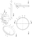
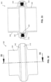
- the invention includes a sealing assembly, generally referred to herein as assembly 10.
- the assembly includes an outer ring 12 having an interior surface 14 and an exterior surface 15.
- the interior surface 14 includes two inwardly extending projections 16, identified independently as 16a, 16b, which together define a seal receiving area 18.
- the projections preferably extend circumferentially around the entire outer ring, however, one skilled in the art would understand that it is within the scope of the invention, based on this disclosure, that a gap or opening or periodic openings may be provided if the end user elects to incorporate them, without departing from the invention. It is preferred that for achieving the best level of seal protection and for maintaining a cohesive assembly, the projections 16 extend around the entire outer ring 12.
- the exterior facing sides 20 of the projections 16 may be oriented with respect to a transverse central axis A OR through the outer ring in parallel or an angle. As shown, each exterior facing side 20a, 20b of respective projections 16a, 16b is in parallel to axis A OR .
- the interior facing sides 22 of the projections 16 may be similarly oriented, to the exterior facing sides, or more preferably as shown, each interior facing side 22a, 22b is angled at a respective angle ⁇ , ⁇ ' with respect to the central transverse axis A OR of the outer ring.
- the angles are preferably the same, but may vary depending on sealing member design. As shown, they are the same.
- the outer ring, as well as the inner ring, described below herein, are each preferably formed so as to include one or more of a metal, a metal alloy or either a heat-moldable or heat sinterable fluoropolymer.
- the outer ring and/or the inner ring may include various metals or alloys thereof for appropriate use in the designated end application.
- Suitable metals and metal alloys for use in semiconductor and/or high temperature processing applications include, but are not limited to, aluminum 6061, aluminum 7075, stainless steel 316, and/or stainless steel 304.
- Suitable fluoropolymers include, without limitation, polytetrafluoroethylene (PTFE) as well as melt-processible fluoroplastic fluoropolymers such as copolymers of perfluoroalkylvinyl ether (PAVE) and tetrafluoroethylene (TFE), commonly known in the art as Teflon TM PFA, copolymers of hexafluoropropylene (HFP) and TFE such as Teflon TM FEP and other suitable melt-processible copolymers.
- PTFE polytetrafluoroethylene
- PAVE perfluoroalkylvinyl ether
- TFE tetrafluoroethylene
- HFP hexafluoropropylene
- TFE such as Teflon TM FEP and other suitable melt-processible copolymers.
- ABS acrylonitrile-butadienestyrene
- ethylene-propylene copolymers polyethersulfones, polyolefins, polyvinyl chlorides, polyimides, polyetherimides, polyamides, polystyrene, polyethylene terephthalate and the like.
- the outer ring will have dimensions configured to mate with an appropriately sized assembly flange and clamp fittings so as to be adaptable to existing piping or other fitted parts. Suitable outer ring dimensions include outer diameters (OD) of about 3 cm to about 8 cm. An inner diameter (ID) will vary somewhat depending on whether it is measured above or below the projections or within the seal receiving area 18 between the projections. On the portions of the outer ring above and below the projections (exterior to surfaces 20a, 20b), the ID is preferably about 2.7 cm to about 7.7 cm. Within the seal receiving area 18 as measured at the central transverse axis A OR , the ID is about 2.5 cm to about 7.5 cm.
- the outer ring may also have a varying height depending on end application, as measured longitudinally along the exterior of the outer ring, of about 6 cm to about 1.2 cm.
- the projections 16 of the outer ring 12 preferably create a seal receiving area that extends outwardly so as to go into the outer ring body while leaving the portions of the outer ring exterior to the projections thicker as noted above with respect to the ID dimensions. It will be understood by one skilled in the art, based on this disclosure that the projection angles, ring thickness and sizing can be varied within the scope of the invention.
- the inner ring 24 for use with assembly 10 has an exterior surface 26 and an interior surface 28.
- the exterior surface 26 preferably has two outwardly extending projections 30 (independently 30a, 30b) that together define a seal receiving area 32.
- the projections 30 preferably extend circumferentially around the entire inner ring, however, one skilled in the art would understand that it is within the scope of the invention, based on this disclosure, that a gap or opening or periodic openings may be provided if the end user elects to incorporate them, without departing from the invention. It is preferred that for achieving the best level of seal protection and for maintaining a cohesive assembly, however, that the projections 30 extend around the entire inner ring 24.
- the exterior facing sides 34 (independently 34a, 34b) of the projections 30 may be oriented with respect to a transverse central axis A IR through the inner ring in parallel or at an angle. As shown, each exterior facing side 34a, 34b of respective projections 30a, 30b is in parallel to axis A IR .
- the interior facing sides 36 (independently 36a, 36b) of the projections 30 may be similarly oriented, to the exterior facing sides, or more preferably as shown, each interior facing side 36a, 36b is angled at a respective angle ⁇ , ⁇ ' with respect to the central transverse axis A IR of the inner ring.
- the angles are preferably the same, but may vary depending on sealing member design. As shown, they are the same.
- the inner ring 24 may be formed using any of the materials noted above with respect to the outer ring 12.
- the inner ring will have dimensions configured to mate with an appropriately sized assembly flange and clamp fittings as well as so that the projections 30a, 30b of the inner ring 24 contact or mate with the projections 16a, 16b, respectively of the outer ring 12.
- the inner ring dimensions like the outer ring dimension should be varied so as to be adaptable to existing piping or other fitted parts. Suitable inner ring dimensions include inner diameters (ID) of about 1.5 cm to about 6.2 cm. An outer diameter (OD) will vary somewhat depending on whether it is measured above or below the projections 30a, 30b or within the seal receiving area 32 between the projections 30.
- the OD is preferably about 1.0 cm to about 5.3 cm. Within the seal receiving area 32 as measured at the central transverse axis A IR , the OD is about 1.2 cm to about 5.7 cm.
- the inner ring may also have a varying height depending on end application, as measured longitudinally along the exterior of the inner ring, of about 7 cm to about 1.4 cm.
- the projections 30 of the outer ring 24 preferably create a seal receiving area 32 that extends inwardly into the inner ring body from the exterior surface while leaving the portions of the inner ring exterior to the projections 30 thicker as noted above with respect to the OD dimensions. It will be understood by one skilled in the art, based on this disclosure that the projection angles, ring thickness and sizing can be varied within the scope of the invention.
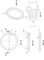
- the seal receiving area 18 of the outer ring 12 of the above-described assembly 10 has a longitudinal cross-sectional profile as shown in Figs. 2-5 of an inwardly facing truncated "V".
- the inwardly facing projections 16 of the outer ring 12 are preferably spaced from each other and each is preferably also spaced from a longitudinal center of the interior surface (the transverse longitudinal axis of the outer ring A OR ) of the outer ring 12 by a distance of about 50% to about 60% of a height H OR of the interior surface 14 of the outer ring 12.
- Each inwardly facing projection 16 of the outer ring 12 as discussed above may be angled away from the transverse central axis through the outer ring A OR and from each other, and each may form an angle ⁇ , ⁇ ' respectively of about 5° to about 25° with the transverse central axis of the outer ring, and preferably an angle of about 10° to about 20° with the transverse central axis of the outer ring.
- the seal receiving area 32 of the inner ring 24 has a longitudinal cross-sectional profile of an outwardly facing truncated "V".
- the outwardly facing projections 30a, 30b of the inner ring 24 may be each spaced from each other and each spaced from a longitudinal center (i.e., the longitudinal axis) of the exterior surface of the inner ring A IR by a distance of about 43% to about 53% of a height H IR of the exterior surface of the inner ring 24.
- Each outwardly facing projection 30a, 30b of the inner ring 24 may be angled away from the transverse central axis A IR through the inner ring 24 and from each other, and each preferably forms an angle ⁇ , ⁇ ' of about 5° to about 25° with the transverse central axis A IR of the inner ring, more preferably an angle of about 10° to about 20° with the transverse central axis of the inner ring.
- both the seal receiving area of the outer ring and the seal receiving area of the inner have longitudinal cross-sectional profiles of an inwardly facing truncated "V" and an outwardly facing truncated "V” as shown in Fig. 2-4 , 7-10 and 13 and as described above with respect to each ring individually.
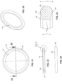
- the assembly 10 further includes a center sealing ring 38 configured to be positioned within the seal receiving areas 18, 32 of the outer ring 12 and the inner ring 24, respectively.
- a center sealing ring 38 configured to be positioned within the seal receiving areas 18, 32 of the outer ring 12 and the inner ring 24, respectively.
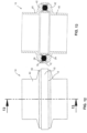
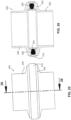
- the elastomeric center sealing ring 38 is enclosed as shown (see Figs. 12, 13 ) within the outer ring 12 and the inner ring 24 so as to protect the center sealing ring 38 while allowing for thermal expansion of the center sealing ring 38.
- the outer and inner rings are assembled around the center sealing ring 38 and are positioned between two mating parts, such as vacuum parts 40.
- the outer ring 12 sits so that its exterior ring body portion is outside of parts 40, and the projections 16a, 16b extend inwardly between parts 40.
- Parts 40 have mating flanges 42 configured to press against the contacting or mating projections 16, 30 of the outer and inner rings assembled.
- the inner ring 24 is seated within the parts 40 so that the inner ring body is positioned inwardly to the mating flanges 42 and the projections 30 of the inner ring are within the mating flanges 42.
- a clamp of any suitable configuration as are known in the art may be used to press the flanges together so as to hold the sealing assembly in place.
- the center sealing ring 38 is preferably formed of an elastomeric material (which may have various additives as are known in the art).
- a fluoroelastomer (FKM) or a perfluoroelastomer (FFKM) are preferred.
- Suitable materials are available from a number of suppliers, including but not limited to Greene, Tweed, of Kulpsville, PA, Dyneon of Minneapolis, Minnesota, Daikin Industries, Ltd., of Japan, Solvay, of Italy, and DuPont Elastomers, LLC of Wilmington, DE.
- FKM fluoroelastomer
- FFKM perfluoroelastomer
- Suitable materials are available from a number of suppliers, including but not limited to Greene, Tweed, of Kulpsville, PA, Dyneon of Minneapolis, Minnesota, Daikin Industries, Ltd., of Japan, Solvay, of Italy, and DuPont Elastomers, LLC of Wilmington, DE.
- other elastomers may be used including silicone e
- the barrel-shaped embodiment as shown preferably has an ID of about 1.5 cm to about 5.6 cm and an OD of about 2.5 cm to about 6.8 cm.
- the height of the seal at its largest dimension measured across the center of each upper and lower curved bump on the upper and lower surface 48, 50 respectively is about 0.45 cm to about 0.51 cm.
- the height h 1 measures about 0.25 cm to about 0.40 cm.
- the size and angled configuration may be varied within the truncated sideways barrel embodiment to accommodate varying projection and ring designs within the scope of the invention.
- a further an assembly 200 is provided having an outer ring 212 and an inner ring 224 which are also essentially the same as the outer and inner rings 12, 24 of assembly 10, with the understanding that with a variation in center sealing ring configuration, one may adjust the outer and inner ring dimensions if desired.
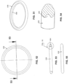
- the assembly 200 has a center sealing ring 238 having a truncated side-ways tear drop shape with an inner facing side 244 that is curved and an outer facing side 246 that is also curved, wherein the inner facing side 244 is preferably smaller in height than the outer facing side 246. The height of such a design would decrease on both the upper side 248 and the lower side 250 of the center sealing ring 238 at a constant rate of decreasing height to provide the desired shape.
- the center sealing ring 338 having the truncated side-ways tear drop-shaped with flat sides 344, 346 shown in Figs. 33-38 in embodiment 300 as shown preferably has an ID of about 1.5 cm to about 5.8 cm and an OD of about 2.5 cm to about 6.9 cm.
- the height h 6 of the seal at its OD is measured as the largest dimension between the highest and lowest points on the exterior portion on each of the upper and lower surfaces 348, 350, respectively, which is about 0.45 cm to about 0.51 cm.
- the height h 7 as measured along the highest and lowest points on the interior portion of the sealing ring and measures about 0.28 cm to about 0.33 cm.
- the size and angled configuration may be varied within the truncated sideways tear drop embodiment with flat sides to accommodate varying projection and ring designs within the scope of the invention.
- Each inwardly facing projection 416 of the outer ring 412 may be angled away from a transverse central axis A OR through the outer ring and from each other, and each preferably like embodiment 10 also forms an angle of about 5° to about 25° with the transverse central axis of the outer ring, and more preferably about 10° to about 20° with the transverse central axis of the outer ring.
- the outer ring and/or the inner ring in this embodiment may be formed of the same materials used for embodiments 10, 100, 200 and 300.
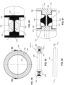
- the invention includes a bonded sealing assembly 500 for high temperature applications.
- This embodiment provides a sealing ring body 566 having a longitudinal cross-section having an outer ring portion 568, an inner ring portion 570 and a central transversely extending bridge 572 that extends between the outer and the inner ring portions 568, 570.
- the outer ring portion 568 has an inwardly extending rectangular portion 574 and the inner ring portion has an inwardly extending rectangular portion 576.
- Each of the rectangular portions 574, 576 of the outer ring portion and the inner ring portion 576 are positioned so as to be longitudinally centered with respect to a central transverse axis A SRB through the sealing ring body.
- the bridge 572 has an upper surface 578 and a lower surface 580.
- the outer and inner ring portions 568, 570 together with and the bridge 572 further define an upper seal receiving area 582 and a lower seal receiving area 584.
- the embodiment further includes an upper seal lobe portion 586 and a lower seal lobe portion 588, each seal portion, 586, 588 is bonded respectively to the upper surface 578 and the lower surface 580 of the bridge 572.
- Each lobe portion 586, 588 is thus respectively located within each of the respective seal receiving areas 582, 584 of the sealing ring body 566.
- the upper and the lower seal lobe portions 586, 588 each have respectively an upwardly extending and a downwardly extending generally parabolic longitudinal cross-section as best shown in Figs. 59, 60 and 61 .
- troughs T form on the upper and lower portions for compression and expansion of the ring.
- the sealing material (see Fig. 60 ) preferably extends along the interior of the sealing body 566 along the perimeter of the seal receiving areas 582, 584.
- the sealing ring body 566 may be formed of any of the metals, metal alloys and/or a fluoropolymers noted above with respect to prior embodiments.
- the upper and lower seal lobe portions preferably comprise elastomers.
- the sealing ring body and the seal lobe portions may be chemically or mechanically bonded.
- mechanically bonding the seal small openings may be formed in the sealing ring body on the surfaces facing the seal receiving areas and upon molding and curing, the elastomeric material will vulcanize and expand to mechanically lock the sealing lobes into place.
- chemically bonding any chemical bonding agent known or to be developed in the art may be used that is compatible with the materials used to form the sealing lobes (which may be a variety of elastomers noted elsewhere herein) to the material used to form the sealing ring body.
- the seal receiving area 418 of the outer ring 412 in this embodiment preferably has a longitudinal cross-sectional profile of an inwardly facing truncated "V" as with the outer ring 12 of embodiment 10.
- the inwardly facing projections 416a, 416b of the outer ring 412 may each be spaced from each other and each spaced from a longitudinal center along the transverse center axis A OR of the interior surface 414 of the outer ring 412 by a distance of about 50% to about 60% of a height H OR ' of the interior surface of the outer ring 412.
- Each inwardly facing projection 416 of the outer ring 412 may be angled away from a transverse central axis A OR through the outer ring and from each other, and each preferably like embodiment 10 also forms an angle of about 5° to about 25° with the transverse central axis of the outer ring, and more preferably about 10° to about 20° with the transverse central axis of the outer ring.
- the outer ring and/or the inner ring in this embodiment may be formed of the same materials used for embodiments 10, 100, 200 and 300.
- the invention includes a bonded sealing assembly 500 for high temperature applications.
- This embodiment provides a sealing ring body 566 having a longitudinal cross-section having an outer ring portion 568, an inner ring portion 570 and a central transversely extending bridge 572 that extends between the outer and the inner ring portions 568, 570.
- the outer ring portion 568 has an inwardly extending rectangular portion 574 and the inner ring portion has an inwardly extending rectangular portion 576.
- Each of the rectangular portions 574, 576 of the outer ring portion and the inner ring portion 576 are positioned so as to be longitudinally centered with respect to a central transverse axis A SRB through the sealing ring body.
- the bridge 572 has an upper surface 578 and a lower surface 580.
- the outer and inner ring portions 568, 570 together with and the bridge 572 further define an upper seal receiving area 582 and a lower seal receiving area 584.
- the embodiment further includes an upper seal lobe portion 586 and a lower seal lobe portion 588, each seal portion, 586, 588 is bonded respectively to the upper surface 578 and the lower surface 580 of the bridge 572.
- Each lobe portion 586, 588 is thus respectively located within each of the respective seal receiving areas 582, 584 of the sealing ring body 566.
- the upper and the lower seal lobe portions 586, 588 each have respectively an upwardly extending and a downwardly extending generally parabolic longitudinal cross-section as best shown in Figs. 59, 60 and 61 .
- troughs T form on the upper and lower portions for compression and expansion of the ring.
- the sealing material (see Fig. 60 ) preferably extends along the interior of the sealing body 566 along the perimeter of the seal receiving areas 582, 584.
- the sealing ring body 566 may be formed of any of the metals, metal alloys and/or a fluoropolymers noted above with respect to prior embodiments.
- the upper and lower seal lobe portions preferably comprise elastomers.
- the sealing ring body and the seal lobe portions may be chemically or mechanically bonded.
- mechanically bonding the seal small openings may be formed in the sealing ring body on the surfaces facing the seal receiving areas and upon molding and curing, the elastomeric material will vulcanize and expand to mechanically lock the sealing lobes into place.
- chemically bonding any chemical bonding agent known or to be developed in the art may be used that is compatible with the materials used to form the sealing lobes (which may be a variety of elastomers noted elsewhere herein) to the material used to form the sealing ring body.
Landscapes
- Engineering & Computer Science (AREA)
- General Engineering & Computer Science (AREA)
- Mechanical Engineering (AREA)
- Physics & Mathematics (AREA)
- Fluid Mechanics (AREA)
- Gasket Seals (AREA)
Claims (14)
- Utilisation d'un ensemble d'étanchéité installé dans une application à haute température ayant une température de service d'environ 100°C à environ 300°C, tel qu'un ensemble d'étanchéité sous vide pour la fabrication de semi-conducteurs, l'ensemble d'étanchéité comprenant :- une bague extérieure (12; 112 ; 212 ; 312) ayant une surface intérieure (14) avec deux saillies s'étendant vers l'intérieur (16a, 16b) définissant une zone de réception du joint (18) ;- une bague intérieure (24 ; 124 ; 224 ; 324) ayant une surface extérieure (26) comportant deux saillies (30a, 30b) s'étendant vers l'extérieur et définissant une zone de réception du joint (32) ;- une bague d'étanchéité centrale (38) comprenant un élastomère et configurée pour être positionnée à l'intérieur des zones de réception du joint (18, 32) de la bague extérieure (12 ; 112 ; 212 ; 312) et de la bague intérieure (24 ; 124 ; 224 ; 324),dans laquelle une zone de réception de joint (18) de la bague extérieure a un profil de section transversale longitudinale en forme de V tronqué tourné vers l'intérieur et chaque saillie tournée vers l'intérieur (16a, 16b) de la bague extérieure (12) est inclinée par rapport à un axe central transversal de la bague extérieure (12) et l'une par rapport à l'autre, et chacune forme un angle (α, α') d'environ 5° à environ 25° avec l'axe central transversal de la bague extérieure (12) ;et dans laquelle la bague d'étanchéité centrale en élastomère (38 ; 138 ; 238 ; 338) est enfermée à l'intérieur des bagues extérieures et intérieures (12, 24) pour protéger la bague d'étanchéité centrale (38 ; 138 ; 238 ; 338) et permettre la dilatation thermique de la bague d'étanchéité centrale (38 ; 138 ; 238 ; 338).
- Utilisation de l'ensemble d'étanchéité selon la revendication 1, dans laquelle une zone de réception du joint (32) de la bague intérieure a un profil de section transversale longitudinale en forme de V tronqué tourné vers l'extérieur et chaque saillie tournée vers l'extérieur (30a, 30b) de la bague intérieure (24) est inclinée par rapport à un axe central transversal traversant la bague intérieure (24) et l'une par rapport à l'autre et chacune forme un angle (β, β') d'environ 5° à environ 25° avec l'axe central transversal de la bague intérieure (24).
- Utilisation de l'ensemble d'étanchéité selon la revendication 1 ou 2, dans laquelle l'application à haute température est un ensemble d'étanchéité sous vide utilisé dans la fabrication de semi-conducteurs.
- Utilisation de l'ensemble d'étanchéité selon la revendication 1 ou 2, dans laquelle l'application à haute température comprend une température de service d'environ 180°C à environ 300°C.
- Utilisation de l'ensemble d'étanchéité selon la revendication 1 ou 2, dans laquelle l'élastomère est un élastomère fluoré ou un élastomère perfluoré.
- Utilisation de l'ensemble d'étanchéité selon la revendication 1 ou 2, dans lequel les saillies tournées vers l'intérieur (16a, 16b) de la bague extérieure (12) sont espacées l'une de l'autre et sont espacées d'un centre longitudinal de la surface intérieure de la bague extérieure d'une distance d'environ 50% à environ 60% d'une hauteur de la surface intérieure (14) de la bague extérieure (12).
- Utilisation de l'ensemble d'étanchéité selon la revendication 1 ou 2, dans lequel chaque saillie tournée vers l'intérieur (16a, 16b) de la bague extérieure (12) forme un angle (α, α') d'environ 10° à environ 20° avec l'axe central transversal de la bague extérieure (12).
- Utilisation de l'ensemble d'étanchéité selon la revendication 1 ou 2, dans lequel les saillies tournées vers l'extérieur (30a, 30b) de la bague intérieure (24) sont espacées l'une de l'autre et sont espacées chacune d'un centre longitudinal de la surface extérieure de la bague intérieure d'une distance d'environ 43% à environ 53% d'une hauteur de la surface extérieure de la bague intérieure (24).
- Utilisation de l'ensemble d'étanchéité selon la revendication 2, dans lequel chaque saillie tournée vers l'extérieur (30a, 30b) de la bague intérieure (24) forme un angle (β, β') d'environ 10° à environ 20° avec l'axe central transversal de la bague intérieure (24).
- Utilisation de l'ensemble d'étanchéité selon la revendication 1 ou 2, dans lequel les saillies tournées vers l'intérieur (16a, 16b) de la bague extérieure (12) sont chacune espacées l'une de l'autre et sont chacune espacées d'un centre longitudinal de la surface intérieure (14) de la bague extérieure (12) d'une distance d'environ 50 % à environ 60 % de la hauteur de la surface intérieure (14) de la bague extérieure (12), et dans lequel les saillies tournées vers l'extérieur (30a, 30b) de la bague intérieure (24) sont chacune espacées l'une de l'autre et sont chacune espacées d'un centre longitudinal de la surface extérieure de la bague intérieure (24) d'une distance d'environ 43 % à environ 53 % de la hauteur de la surface extérieure de la bague intérieure (24).
- Utilisation de l'ensemble d'étanchéité selon la revendication 1 ou 2, dans lequel la bague d'étanchéité centrale (38) a une section transversale longitudinale qui a une forme de tonneau latéral.
- Utilisation de l'ensemble d'étanchéité selon la revendication 1 ou 2, dans lequel la bague d'étanchéité centrale (138) a une section transversale longitudinale qui a une forme de goutte d'eau tronquée avec un côté tourné vers l'intérieur (144) qui est plat et un côté tourné vers l'extérieur (146) qui est incurvé dans lequel le côté tourné vers l'intérieur (144) est plus petit que le côté tourné vers l'extérieur (146).
- Utilisation de l'ensemble d'étanchéité selon la revendication 1 ou 2, dans laquelle la bague d'étanchéité centrale (238) a une section transversale longitudinale qui a une forme de goutte d'eau latérale tronquée avec un côté tourné vers l'intérieur (244) qui est courbé et un côté tourné vers l'extérieur (246) qui est courbé, et dans lequel le côté tourné vers l'intérieur (244) est plus petit que le côté tourné vers l'extérieur (246).
- Utilisation de l'ensemble d'étanchéité selon la revendication 1 ou 2, dans lequel la bague d'étanchéité centrale (338) a une section transversale longitudinale qui a une forme de goutte d'eau tronquée avec un côté tourné vers l'intérieur (344) qui est plat et un côté tourné vers l'extérieur (346) qui est plat, et dans lequel le côté tourné vers l'intérieur (344) est plus petite que le côté tourné vers l'extérieur (346).
Applications Claiming Priority (2)
| Application Number | Priority Date | Filing Date | Title |
|---|---|---|---|
| US201562254119P | 2015-11-11 | 2015-11-11 | |
| PCT/US2016/061342 WO2017083524A1 (fr) | 2015-11-11 | 2016-11-10 | Bagues d'étanchéité et ensembles de bagues d'étanchéité pour applications finales à haute température |
Publications (3)
| Publication Number | Publication Date |
|---|---|
| EP3374681A1 EP3374681A1 (fr) | 2018-09-19 |
| EP3374681A4 EP3374681A4 (fr) | 2019-07-24 |
| EP3374681B1 true EP3374681B1 (fr) | 2025-01-22 |
Family
ID=58663490
Family Applications (1)
| Application Number | Title | Priority Date | Filing Date |
|---|---|---|---|
| EP16865004.2A Active EP3374681B1 (fr) | 2015-11-11 | 2016-11-10 | Bagues d'étanchéité et ensembles de bagues d'étanchéité pour applications finales à haute température |
Country Status (7)
| Country | Link |
|---|---|
| US (1) | US11085564B2 (fr) |
| EP (1) | EP3374681B1 (fr) |
| JP (1) | JP6908603B2 (fr) |
| KR (1) | KR102712621B1 (fr) |
| SG (1) | SG11201803589QA (fr) |
| TW (1) | TWI756195B (fr) |
| WO (1) | WO2017083524A1 (fr) |
Families Citing this family (17)
| Publication number | Priority date | Publication date | Assignee | Title |
|---|---|---|---|---|
| WO2016081428A1 (fr) * | 2014-11-18 | 2016-05-26 | Britt Engineering, Inc. | Système de joint torique pour brides en matière plastique renforcée par fibres, thermoplastiques et métalliques |
| US11085564B2 (en) | 2015-11-11 | 2021-08-10 | Greene, Tweed Technologies, Inc. | Sealing rings and sealing ring assemblies for high temperature end applications |
| WO2018218055A1 (fr) * | 2017-05-24 | 2018-11-29 | Garlock Sealing Technologies, Llc | Matériau de joint en ptfe biaxial pourvu d'une charge de pureté élevée |
| CN109084099A (zh) * | 2018-08-20 | 2018-12-25 | 安徽国科生物科技有限公司 | 精准制氧供氧系统 |
| GB2579046B (en) * | 2018-11-15 | 2021-10-27 | Edwards Ltd | Seal for a vacuum pump |
| KR102095864B1 (ko) * | 2019-01-11 | 2020-04-01 | (주)엘오티씨이에스 | 하이브리드 시일을 사용한 배관 장치 및 이를 포함하는 유해가스 처리 설비 |
| JP7382150B2 (ja) * | 2019-03-25 | 2023-11-16 | エドワーズ株式会社 | 真空ポンプ、及び、真空ポンプに用いられるシール部材 |
| CN111780599A (zh) | 2020-06-08 | 2020-10-16 | 华南理工大学 | 一种高温热管的封装方法 |
| CN111963711B (zh) * | 2020-09-07 | 2025-03-04 | 希佛隆阀门集团有限公司 | 一种耐高温高压密封环 |
| US20230089463A1 (en) * | 2021-09-22 | 2023-03-23 | Hamilton Sundstrand Corporation | High temperature fuel seals and methods of making thereof |
| WO2023064452A1 (fr) * | 2021-10-13 | 2023-04-20 | Commscope Technologies Llc | Système d'enceinte de télécommunications |
| US12071942B2 (en) | 2021-10-22 | 2024-08-27 | Hamilton Sundstrand Corporation | Variable displacement pumps |
| JP7849183B2 (ja) * | 2022-02-07 | 2026-04-21 | 株式会社バルカー | シールリング |
| KR20240162030A (ko) * | 2022-03-11 | 2024-11-14 | 가부시키가이샤 코쿠사이 엘렉트릭 | 씰 어셈블리, 반도체 장치의 제조 방법, 기판 처리 방법 및 프로그램 |
| CN116337029A (zh) * | 2023-02-16 | 2023-06-27 | 西安冠华电子科技有限公司 | 一种用于燃气陀螺仪的万向支架 |
| IT202300018735A1 (it) | 2023-09-12 | 2025-03-12 | Eram Tech S R L | Sistema di tenuta ausiliaria per collegamenti flangiati |
| US12449035B1 (en) * | 2024-07-10 | 2025-10-21 | GM Global Technology Operations LLC | Reinforcement ring for gasket |
Family Cites Families (47)
| Publication number | Priority date | Publication date | Assignee | Title |
|---|---|---|---|---|
| GB701614A (en) * | 1951-06-27 | 1953-12-30 | Vickers Electrical Co Ltd | Improvements relating to the sealing of joints in high vacuum and the like systems |
| US3167322A (en) * | 1961-11-27 | 1965-01-26 | Richard W Aichroth | Seal |
| US3215442A (en) * | 1962-04-27 | 1965-11-02 | Parker Hannifin Corp | Fluid seal |
| FR1354823A (fr) * | 1962-10-25 | 1964-03-13 | Joint d'étanchéité | |
| GB1117546A (en) * | 1965-06-28 | 1968-06-19 | Saiecom Sa D Inv S Et D Etudes | Improvements in or relating to fluid-tight seals |
| BE757603A (fr) * | 1969-10-17 | 1971-04-01 | France Etat | Joint statique etanche pour circuit vehiculant tout fluide sousde hautes pressions |
| US4002344A (en) * | 1975-11-12 | 1977-01-11 | Smith Franklyn D | Snap-in flange seal and locator |
| DE2616512C3 (de) * | 1976-04-14 | 1978-08-31 | Kempchen & Co Gmbh, 4200 Oberhausen | Flanschdichtung |
| JPS606822Y2 (ja) | 1978-06-23 | 1985-03-06 | 富士写真フイルム株式会社 | 防水カメラの密閉構造 |
| JPS608573A (ja) | 1983-06-28 | 1985-01-17 | Matsushita Electric Works Ltd | ケ−シングのシ−リング構造 |
| DE3722132A1 (de) | 1987-07-04 | 1989-01-12 | Daimler Benz Ag | Hydraulisch daempfendes lager |
| US4776600A (en) * | 1987-11-23 | 1988-10-11 | Pikotek, Inc. | Dielectric pipe flange gasket |
| DE4242238C2 (de) * | 1992-12-15 | 2001-02-15 | Bosch Gmbh Robert | Dichtring für einen in eine Öffnung eines Gehäuses ragenden Stift |
| US5518257A (en) * | 1993-08-23 | 1996-05-21 | Corrosion Control Corp. | Seal device for flow line applications |
| US5722668A (en) | 1994-04-29 | 1998-03-03 | Applied Materials, Inc. | Protective collar for vacuum seal in a plasma etch reactor |
| US5746434A (en) | 1996-07-09 | 1998-05-05 | Lam Research Corporation | Chamber interfacing O-rings and method for implementing same |
| KR100471772B1 (ko) | 1997-07-11 | 2005-06-07 | 삼성전자주식회사 | 듀얼 스캔 구동 방식의 액정 표시 장치용 기판 |
| US6325390B1 (en) | 1997-08-08 | 2001-12-04 | Itt Manufacturing Enterprises, Inc. | Vacuum flange O-ring center ring |
| JPH11131052A (ja) | 1997-10-31 | 1999-05-18 | Mitsubishi Cable Ind Ltd | シール |
| US6357759B1 (en) | 1999-02-15 | 2002-03-19 | Mitsubishi Cable Industries, Ltd. | Jacket seal |
| GB9925469D0 (en) | 1999-10-27 | 1999-12-29 | Boc Group Plc | Seal assemblies |
| JP4498661B2 (ja) | 2001-07-11 | 2010-07-07 | 株式会社バックス・エスイーブイ | 真空装置用金属製ガスケット及びその製造方法 |
| JP4149931B2 (ja) | 2002-01-31 | 2008-09-17 | デュポン パフォーマンス エラストマーズ エルエルシー | ゲートバルブシールアセンブリ |
| US6869081B1 (en) * | 2002-12-20 | 2005-03-22 | Jjenco, Inc. | Constant seating stress gasket system |
| US7159906B1 (en) | 2003-01-31 | 2007-01-09 | A&N Corporation | Methods and apparatus for flange sealing |
| JP2006071052A (ja) * | 2004-09-06 | 2006-03-16 | Tokura Kogyo Kk | プロセスガス用配管の連結部構造 |
| KR100877283B1 (ko) | 2004-09-17 | 2009-01-07 | 닛폰 바루카 고교 가부시키가이샤 | 복합 실링재 |
| WO2006042164A1 (fr) | 2004-10-08 | 2006-04-20 | Tosoh Smd, Inc. | Joint torique a faible fuite |
| US8141848B2 (en) * | 2005-01-24 | 2012-03-27 | Pentair Residential Filtration, Llc | Piston with integral seals for a water softener control valve |
| JP4668704B2 (ja) | 2005-07-04 | 2011-04-13 | ニチアス株式会社 | Oリング及び真空装置用クランプ形継手 |
| JP4668703B2 (ja) * | 2005-07-04 | 2011-04-13 | ニチアス株式会社 | 真空装置用クランプ形継手 |
| US20070032081A1 (en) | 2005-08-08 | 2007-02-08 | Jeremy Chang | Edge ring assembly with dielectric spacer ring |
| JP5073932B2 (ja) | 2005-09-16 | 2012-11-14 | 三菱電線工業株式会社 | 密封構造体 |
| JP2007173420A (ja) | 2005-12-21 | 2007-07-05 | Kayaba Ind Co Ltd | 平面密封機構、プラズマ遮断シール |
| GB0603318D0 (en) | 2006-02-20 | 2006-03-29 | Boc Group Plc | Seal |
| US7621568B2 (en) * | 2006-04-25 | 2009-11-24 | Visteon Global Technologies, Inc. | Block fitting and seal structure |
| GB0712779D0 (en) | 2007-07-02 | 2007-08-08 | Edwards Ltd | Seal |
| CH699688B1 (de) * | 2008-10-01 | 2012-12-14 | Inficon Gmbh | Flanschverbindung. |
| US8191933B2 (en) * | 2008-07-16 | 2012-06-05 | General Electric Company | Extrusion resistant gasket face seal |
| DE112009002071B4 (de) | 2008-09-05 | 2012-11-08 | Vat Holding Ag | Vakuumventil mit gasdichter Wellendurchführung |
| JP5355578B2 (ja) * | 2008-09-18 | 2013-11-27 | 日本バルカー工業株式会社 | シールプレートおよびシールプレートに用いられるシール部材ならびにこれらの製造方法 |
| US9349621B2 (en) | 2011-05-23 | 2016-05-24 | Lam Research Corporation | Vacuum seal arrangement useful in plasma processing chamber |
| KR20140073081A (ko) | 2012-12-06 | 2014-06-16 | 김동룡 | 실링용 오링 |
| DE102013101263B4 (de) | 2013-02-08 | 2022-12-01 | Denso Corporation | Dichtungsanordnung zwischen zwei Gehäuseteilen |
| KR101471772B1 (ko) | 2013-06-21 | 2014-12-10 | 주식회사 엠앤이 | 진공 배관 접속용 본디드 플랜지 오링 |
| GB2521340B (en) | 2013-10-14 | 2017-10-04 | Edwards Ltd | Vacuum system pipe couplings |
| US11085564B2 (en) | 2015-11-11 | 2021-08-10 | Greene, Tweed Technologies, Inc. | Sealing rings and sealing ring assemblies for high temperature end applications |
-
2016
- 2016-11-10 US US15/348,552 patent/US11085564B2/en active Active
- 2016-11-10 JP JP2018520405A patent/JP6908603B2/ja active Active
- 2016-11-10 KR KR1020187013501A patent/KR102712621B1/ko active Active
- 2016-11-10 SG SG11201803589QA patent/SG11201803589QA/en unknown
- 2016-11-10 WO PCT/US2016/061342 patent/WO2017083524A1/fr not_active Ceased
- 2016-11-10 EP EP16865004.2A patent/EP3374681B1/fr active Active
- 2016-11-11 TW TW105136848A patent/TWI756195B/zh active
Also Published As
| Publication number | Publication date |
|---|---|
| JP2018533702A (ja) | 2018-11-15 |
| KR102712621B1 (ko) | 2024-10-04 |
| KR20180079342A (ko) | 2018-07-10 |
| JP6908603B2 (ja) | 2021-07-28 |
| WO2017083524A1 (fr) | 2017-05-18 |
| SG11201803589QA (en) | 2018-05-30 |
| US20170130881A1 (en) | 2017-05-11 |
| TWI756195B (zh) | 2022-03-01 |
| EP3374681A1 (fr) | 2018-09-19 |
| EP3374681A4 (fr) | 2019-07-24 |
| TW201730461A (zh) | 2017-09-01 |
| US11085564B2 (en) | 2021-08-10 |
Similar Documents
| Publication | Publication Date | Title |
|---|---|---|
| US11085564B2 (en) | Sealing rings and sealing ring assemblies for high temperature end applications | |
| US8794638B2 (en) | Sealing array for high temperature applications | |
| EP2334959B1 (fr) | Joint de raccord de tube hygienique | |
| US20140216636A1 (en) | Rubber/resin composite seal material | |
| KR102447064B1 (ko) | 복합 시일재 | |
| US12215787B2 (en) | Seal with insert and methods of making and using the same | |
| EP1096183A2 (fr) | Dispositifs d'étanchéité | |
| CN1465000A (zh) | 恒压调节器 | |
| JP6738741B2 (ja) | ライニング型バタフライバルブ | |
| US20130313788A1 (en) | Spiral wound gasket | |
| KR101915472B1 (ko) | 부산물 트랩 방지용 배관 | |
| US12060943B2 (en) | Seals and methods of making and using the same | |
| KR101471772B1 (ko) | 진공 배관 접속용 본디드 플랜지 오링 | |
| JP5767592B2 (ja) | 樹脂製ヘルール継手 | |
| US20230358314A1 (en) | Seals and methods of making and using the same | |
| US5215337A (en) | Containment piping system with expansion seal | |
| WO2004001269A1 (fr) | Structure de tuyau flexible relie a une piece d'extremite comprenant une garniture d'etancheite annulaire auto-etanche | |
| JP7503549B2 (ja) | 真空ポンプ用シール | |
| US20240151308A1 (en) | Sealing structure and sealing material | |
| WO2013177392A1 (fr) | Joint spiralé | |
| KR101695199B1 (ko) | 라이닝플랜지 및 라이닝플랜지결합체 |
Legal Events
| Date | Code | Title | Description |
|---|---|---|---|
| STAA | Information on the status of an ep patent application or granted ep patent |
Free format text: STATUS: THE INTERNATIONAL PUBLICATION HAS BEEN MADE |
|
| PUAI | Public reference made under article 153(3) epc to a published international application that has entered the european phase |
Free format text: ORIGINAL CODE: 0009012 |
|
| STAA | Information on the status of an ep patent application or granted ep patent |
Free format text: STATUS: REQUEST FOR EXAMINATION WAS MADE |
|
| 17P | Request for examination filed |
Effective date: 20180608 |
|
| AK | Designated contracting states |
Kind code of ref document: A1 Designated state(s): AL AT BE BG CH CY CZ DE DK EE ES FI FR GB GR HR HU IE IS IT LI LT LU LV MC MK MT NL NO PL PT RO RS SE SI SK SM TR |
|
| AX | Request for extension of the european patent |
Extension state: BA ME |
|
| DAV | Request for validation of the european patent (deleted) | ||
| DAX | Request for extension of the european patent (deleted) | ||
| RIC1 | Information provided on ipc code assigned before grant |
Ipc: F16L 23/04 20060101ALI20190318BHEP Ipc: F16L 23/18 20060101AFI20190318BHEP Ipc: F16J 15/06 20060101ALI20190318BHEP Ipc: F16J 15/02 20060101ALI20190318BHEP Ipc: C09K 3/10 20060101ALI20190318BHEP Ipc: F16J 15/32 20160101ALI20190318BHEP Ipc: F16J 15/28 20060101ALI20190318BHEP |
|
| A4 | Supplementary search report drawn up and despatched |
Effective date: 20190626 |
|
| RIC1 | Information provided on ipc code assigned before grant |
Ipc: F16J 15/28 20060101ALI20190619BHEP Ipc: F16J 15/06 20060101ALI20190619BHEP Ipc: F16J 15/32 20160101ALI20190619BHEP Ipc: F16L 23/18 20060101AFI20190619BHEP Ipc: C09K 3/10 20060101ALI20190619BHEP Ipc: F16J 15/02 20060101ALI20190619BHEP Ipc: F16L 23/04 20060101ALI20190619BHEP |
|
| STAA | Information on the status of an ep patent application or granted ep patent |
Free format text: STATUS: EXAMINATION IS IN PROGRESS |
|
| 17Q | First examination report despatched |
Effective date: 20200515 |
|
| GRAP | Despatch of communication of intention to grant a patent |
Free format text: ORIGINAL CODE: EPIDOSNIGR1 |
|
| STAA | Information on the status of an ep patent application or granted ep patent |
Free format text: STATUS: GRANT OF PATENT IS INTENDED |
|
| INTG | Intention to grant announced |
Effective date: 20240909 |
|
| GRAS | Grant fee paid |
Free format text: ORIGINAL CODE: EPIDOSNIGR3 |
|
| GRAA | (expected) grant |
Free format text: ORIGINAL CODE: 0009210 |
|
| STAA | Information on the status of an ep patent application or granted ep patent |
Free format text: STATUS: THE PATENT HAS BEEN GRANTED |
|
| P01 | Opt-out of the competence of the unified patent court (upc) registered |
Free format text: CASE NUMBER: APP_62461/2024 Effective date: 20241122 |
|
| AK | Designated contracting states |
Kind code of ref document: B1 Designated state(s): AL AT BE BG CH CY CZ DE DK EE ES FI FR GB GR HR HU IE IS IT LI LT LU LV MC MK MT NL NO PL PT RO RS SE SI SK SM TR |
|
| REG | Reference to a national code |
Ref country code: GB Ref legal event code: FG4D |
|
| REG | Reference to a national code |
Ref country code: CH Ref legal event code: EP |
|
| REG | Reference to a national code |
Ref country code: IE Ref legal event code: FG4D |
|
| REG | Reference to a national code |
Ref country code: DE Ref legal event code: R096 Ref document number: 602016091040 Country of ref document: DE |
|
| REG | Reference to a national code |
Ref country code: NL Ref legal event code: MP Effective date: 20250122 |
|
| PG25 | Lapsed in a contracting state [announced via postgrant information from national office to epo] |
Ref country code: NL Free format text: LAPSE BECAUSE OF FAILURE TO SUBMIT A TRANSLATION OF THE DESCRIPTION OR TO PAY THE FEE WITHIN THE PRESCRIBED TIME-LIMIT Effective date: 20250122 |
|
| PG25 | Lapsed in a contracting state [announced via postgrant information from national office to epo] |
Ref country code: RS Free format text: LAPSE BECAUSE OF FAILURE TO SUBMIT A TRANSLATION OF THE DESCRIPTION OR TO PAY THE FEE WITHIN THE PRESCRIBED TIME-LIMIT Effective date: 20250422 |
|
| PG25 | Lapsed in a contracting state [announced via postgrant information from national office to epo] |
Ref country code: FI Free format text: LAPSE BECAUSE OF FAILURE TO SUBMIT A TRANSLATION OF THE DESCRIPTION OR TO PAY THE FEE WITHIN THE PRESCRIBED TIME-LIMIT Effective date: 20250122 |
|
| PG25 | Lapsed in a contracting state [announced via postgrant information from national office to epo] |
Ref country code: PL Free format text: LAPSE BECAUSE OF FAILURE TO SUBMIT A TRANSLATION OF THE DESCRIPTION OR TO PAY THE FEE WITHIN THE PRESCRIBED TIME-LIMIT Effective date: 20250122 |
|
| PG25 | Lapsed in a contracting state [announced via postgrant information from national office to epo] |
Ref country code: ES Free format text: LAPSE BECAUSE OF FAILURE TO SUBMIT A TRANSLATION OF THE DESCRIPTION OR TO PAY THE FEE WITHIN THE PRESCRIBED TIME-LIMIT Effective date: 20250122 |
|
| REG | Reference to a national code |
Ref country code: LT Ref legal event code: MG9D |
|
| PG25 | Lapsed in a contracting state [announced via postgrant information from national office to epo] |
Ref country code: NO Free format text: LAPSE BECAUSE OF FAILURE TO SUBMIT A TRANSLATION OF THE DESCRIPTION OR TO PAY THE FEE WITHIN THE PRESCRIBED TIME-LIMIT Effective date: 20250422 Ref country code: IS Free format text: LAPSE BECAUSE OF FAILURE TO SUBMIT A TRANSLATION OF THE DESCRIPTION OR TO PAY THE FEE WITHIN THE PRESCRIBED TIME-LIMIT Effective date: 20250522 |
|
| REG | Reference to a national code |
Ref country code: AT Ref legal event code: MK05 Ref document number: 1761696 Country of ref document: AT Kind code of ref document: T Effective date: 20250122 |
|
| PG25 | Lapsed in a contracting state [announced via postgrant information from national office to epo] |
Ref country code: HR Free format text: LAPSE BECAUSE OF FAILURE TO SUBMIT A TRANSLATION OF THE DESCRIPTION OR TO PAY THE FEE WITHIN THE PRESCRIBED TIME-LIMIT Effective date: 20250122 |
|
| PG25 | Lapsed in a contracting state [announced via postgrant information from national office to epo] |
Ref country code: PT Free format text: LAPSE BECAUSE OF FAILURE TO SUBMIT A TRANSLATION OF THE DESCRIPTION OR TO PAY THE FEE WITHIN THE PRESCRIBED TIME-LIMIT Effective date: 20250522 Ref country code: LV Free format text: LAPSE BECAUSE OF FAILURE TO SUBMIT A TRANSLATION OF THE DESCRIPTION OR TO PAY THE FEE WITHIN THE PRESCRIBED TIME-LIMIT Effective date: 20250122 |
|
| PG25 | Lapsed in a contracting state [announced via postgrant information from national office to epo] |
Ref country code: BG Free format text: LAPSE BECAUSE OF FAILURE TO SUBMIT A TRANSLATION OF THE DESCRIPTION OR TO PAY THE FEE WITHIN THE PRESCRIBED TIME-LIMIT Effective date: 20250122 Ref country code: GR Free format text: LAPSE BECAUSE OF FAILURE TO SUBMIT A TRANSLATION OF THE DESCRIPTION OR TO PAY THE FEE WITHIN THE PRESCRIBED TIME-LIMIT Effective date: 20250423 |
|
| PG25 | Lapsed in a contracting state [announced via postgrant information from national office to epo] |
Ref country code: AT Free format text: LAPSE BECAUSE OF FAILURE TO SUBMIT A TRANSLATION OF THE DESCRIPTION OR TO PAY THE FEE WITHIN THE PRESCRIBED TIME-LIMIT Effective date: 20250122 |
|
| PG25 | Lapsed in a contracting state [announced via postgrant information from national office to epo] |
Ref country code: SE Free format text: LAPSE BECAUSE OF FAILURE TO SUBMIT A TRANSLATION OF THE DESCRIPTION OR TO PAY THE FEE WITHIN THE PRESCRIBED TIME-LIMIT Effective date: 20250122 |
|
| PG25 | Lapsed in a contracting state [announced via postgrant information from national office to epo] |
Ref country code: SM Free format text: LAPSE BECAUSE OF FAILURE TO SUBMIT A TRANSLATION OF THE DESCRIPTION OR TO PAY THE FEE WITHIN THE PRESCRIBED TIME-LIMIT Effective date: 20250122 |
|
| PG25 | Lapsed in a contracting state [announced via postgrant information from national office to epo] |
Ref country code: DK Free format text: LAPSE BECAUSE OF FAILURE TO SUBMIT A TRANSLATION OF THE DESCRIPTION OR TO PAY THE FEE WITHIN THE PRESCRIBED TIME-LIMIT Effective date: 20250122 |
|
| PG25 | Lapsed in a contracting state [announced via postgrant information from national office to epo] |
Ref country code: IT Free format text: LAPSE BECAUSE OF FAILURE TO SUBMIT A TRANSLATION OF THE DESCRIPTION OR TO PAY THE FEE WITHIN THE PRESCRIBED TIME-LIMIT Effective date: 20250122 |
|
| PG25 | Lapsed in a contracting state [announced via postgrant information from national office to epo] |
Ref country code: EE Free format text: LAPSE BECAUSE OF FAILURE TO SUBMIT A TRANSLATION OF THE DESCRIPTION OR TO PAY THE FEE WITHIN THE PRESCRIBED TIME-LIMIT Effective date: 20250122 Ref country code: CZ Free format text: LAPSE BECAUSE OF FAILURE TO SUBMIT A TRANSLATION OF THE DESCRIPTION OR TO PAY THE FEE WITHIN THE PRESCRIBED TIME-LIMIT Effective date: 20250122 |
|
| REG | Reference to a national code |
Ref country code: DE Ref legal event code: R097 Ref document number: 602016091040 Country of ref document: DE |
|
| PG25 | Lapsed in a contracting state [announced via postgrant information from national office to epo] |
Ref country code: RO Free format text: LAPSE BECAUSE OF FAILURE TO SUBMIT A TRANSLATION OF THE DESCRIPTION OR TO PAY THE FEE WITHIN THE PRESCRIBED TIME-LIMIT Effective date: 20250122 |
|
| PG25 | Lapsed in a contracting state [announced via postgrant information from national office to epo] |
Ref country code: SK Free format text: LAPSE BECAUSE OF FAILURE TO SUBMIT A TRANSLATION OF THE DESCRIPTION OR TO PAY THE FEE WITHIN THE PRESCRIBED TIME-LIMIT Effective date: 20250122 |
|
| PLBE | No opposition filed within time limit |
Free format text: ORIGINAL CODE: 0009261 |
|
| STAA | Information on the status of an ep patent application or granted ep patent |
Free format text: STATUS: NO OPPOSITION FILED WITHIN TIME LIMIT |
|
| REG | Reference to a national code |
Ref country code: CH Ref legal event code: L10 Free format text: ST27 STATUS EVENT CODE: U-0-0-L10-L00 (AS PROVIDED BY THE NATIONAL OFFICE) Effective date: 20251203 |
|
| 26N | No opposition filed |
Effective date: 20251023 |
|
| PGFP | Annual fee paid to national office [announced via postgrant information from national office to epo] |
Ref country code: DE Payment date: 20251014 Year of fee payment: 10 |
|
| PGFP | Annual fee paid to national office [announced via postgrant information from national office to epo] |
Ref country code: GB Payment date: 20251016 Year of fee payment: 10 |
|
| REG | Reference to a national code |
Ref country code: CH Ref legal event code: H13 Free format text: ST27 STATUS EVENT CODE: U-0-0-H10-H13 (AS PROVIDED BY THE NATIONAL OFFICE) Effective date: 20260623 |
|
| PG25 | Lapsed in a contracting state [announced via postgrant information from national office to epo] |
Ref country code: LT Free format text: LAPSE BECAUSE OF FAILURE TO SUBMIT A TRANSLATION OF THE DESCRIPTION OR TO PAY THE FEE WITHIN THE PRESCRIBED TIME-LIMIT Effective date: 20250122 |
|
| PG25 | Lapsed in a contracting state [announced via postgrant information from national office to epo] |
Ref country code: MC Free format text: LAPSE BECAUSE OF FAILURE TO SUBMIT A TRANSLATION OF THE DESCRIPTION OR TO PAY THE FEE WITHIN THE PRESCRIBED TIME-LIMIT Effective date: 20250122 |
|
| PG25 | Lapsed in a contracting state [announced via postgrant information from national office to epo] |
Ref country code: CH Free format text: LAPSE BECAUSE OF NON-PAYMENT OF DUE FEES Effective date: 20251130 Ref country code: LU Free format text: LAPSE BECAUSE OF NON-PAYMENT OF DUE FEES Effective date: 20251110 |