EP3375272A1 - Rouleaux de compactage pour le travail du sol - Google Patents
Rouleaux de compactage pour le travail du sol Download PDFInfo
- Publication number
- EP3375272A1 EP3375272A1 EP18161333.2A EP18161333A EP3375272A1 EP 3375272 A1 EP3375272 A1 EP 3375272A1 EP 18161333 A EP18161333 A EP 18161333A EP 3375272 A1 EP3375272 A1 EP 3375272A1
- Authority
- EP
- European Patent Office
- Prior art keywords
- spring elements
- carrier profile
- mounting
- packer roller
- carrier
- Prior art date
- Legal status (The legal status is an assumption and is not a legal conclusion. Google has not performed a legal analysis and makes no representation as to the accuracy of the status listed.)
- Granted
Links
Images



Classifications
-
- A—HUMAN NECESSITIES
- A01—AGRICULTURE; FORESTRY; ANIMAL HUSBANDRY; HUNTING; TRAPPING; FISHING
- A01B—SOIL WORKING IN AGRICULTURE OR FORESTRY; PARTS, DETAILS, OR ACCESSORIES OF AGRICULTURAL MACHINES OR IMPLEMENTS, IN GENERAL
- A01B29/00—Rollers
- A01B29/04—Rollers with non-smooth surface formed of rotatably-mounted rings or discs or with projections or ribs on the roller body; Land packers
- A01B29/041—Rollers with non-smooth surface formed of rotatably-mounted rings or discs or with projections or ribs on the roller body; Land packers of "Cambridge"-type, i.e. the soil-pressing rings being stacked on a shaft
Definitions
- the present invention relates to a packer roller for tillage with the features of independent claim 1, which is particularly intended or suitable for agricultural use.
- Such a packer roller is, for example, by the EP 2 433 481 B1 known.
- the packer roller disclosed here initially consists of a horizontally extending carrier profile which is rotatably mounted on an agricultural machine by means of a bearing unit.
- On the carrier profile a plurality of spring elements rotating with the carrier profile are arranged by means of spokes.
- the spring elements fastened to the spokes form a circular circumferential or running surface and are each designed so elastically that a targeted reconsolidation is achieved by means of the spring elements and a crumbly soil structure is created.
- the spokes provide a firm connection between the carrier profile and the respective spring element, wherein the spoke is welded to the carrier profile and is rigidly connected by means of a screw and / or tab connection with the inner circumferential surface of the spring element. Since at least two spokes are required for connecting the spring elements to the carrier profile, which spokes are welded to the carrier profile, the packer roller is very erintensiv and also costly due to the large number of spokes to be welded. Furthermore, a simple or problem-free change of parts by the welded spokes with damaged packer rollers or carrier profiles is not possible or possible only by great effort, but this is not practical.
- a packer roller goes out of the EP 2 386 196 A1 out.
- the spokes of the packer roller are formed as quarter-ring segments, which are screwed to each other and clamped to a support profile.
- the clamping of the quarter-ring segments with the carrier profile has proven not to be practical, since the clamping forces are sometimes too low and move the quarter-ring segments axially on the carrier profile. This is especially due to the high Strains that act on the packer roller during tillage caused.
- the design of the packer roller with quarter-ring segments and one spring element in each case at least five parts necessary to create a packer ring, which in turn the parts cost is very high and thus the packer roller is very expensive.
- the spring elements or the section forming the spoke for example by a cross-sectional increase, so that it withstands higher loads, is only conditionally possible, as this would also result in a change in the elastic properties of the tread forming sections, which in turn the soil working or reconsolidation performed by the packer roller is degraded. This would also lead to an unwanted increase in weight, which in turn would increase the forces and loads acting on the agricultural machine using the packer roller.
- the in the WO 2012/060770 A1 spring elements shown have mounting surfaces, which are formed corresponding to the circumference of the carrier profile and rest on the outer circumference of the carrier profile.
- the attachment of the spring elements on the carrier profile is carried out such that fastening means penetrate the carrier profile and each connect the two opposite mounting surfaces of the two spring elements together.
- fastening means penetrate the carrier profile and each connect the two opposite mounting surfaces of the two spring elements together.
- EP 0 998 185 B1 extend from the carrier profile respectively carrier or flanges, which are firmly connected or welded to the tube circumference of the carrier profile.
- Fixing elements or spring elements fastened each consisting of an inner, radially outwardly extending portion and an outer, formed in the form of a circular segment section.
- the inner portion is screwed in particular on the carrier or on the flange, riveted or the like.
- the apparatus includes rotating reaming tools in roll or tire form, such as a punch tool.
- the rotating broaching tool consists of individual spaced-apart rings, which form a closed or partially interrupted cylindrical peripheral surface or a circumferential ring.
- the rings each comprise a spoke, which are each welded with their front side to a continuous, transversely to the direction of the carrier profile provided.
- the welding of the spokes on the carrier profile has the disadvantages that the resilient and elastic properties of the rings are limited and reduced and that the welds break at higher loads.
- the present invention seeks to propose a simpler and with little overhead cost produced and thus inexpensive to produce packer roller, which allows effective tillage and has improved stability.
- the invention proposes a packer roller for tillage, which packer roller is used in particular in agricultural machinery for tillage and / or sowing of Verteilgut use and reconsolidation of a previously loosened farmland and to produce a fine crumbly soil structure.
- the packer roller can also serve to guide the depth of the respective agricultural machine.
- the packer roller is in particular rotatably mounted on the agricultural machine and has a carrier profile on which in each case, preferably regularly, spaced from one another a plurality of spring elements are arranged.
- the support profile may be assigned to each end face a bearing flange, by means of which the packer roller, for example.
- On a frame structure of an agricultural machine is rotatably mounted.
- the bearing flange can in this case be non-positively, material and / or positive fit, in particular welded and bolted to the carrier profile, but also be connected in other ways with this.
- the bearing flange may also have a round inner cross-section in order to simplify, for example, the mounting of a bearing.
- the spring elements are each designed such that in each case at least two, three or more opposing or connected spring elements form an at least substantially circular or a circular tread or a packer ring.
- the spring elements each have at least one outer substantially circular peripheral surface, two inner mounting surfaces corresponding at least in sections to the contour of the carrier profile, and two connecting surfaces extending between the outer peripheral surface and the inner mounting surface.
- the connecting surfaces or connecting portions may each be arranged radially and / or at a certain angle between the inner mounting surface and the outer peripheral surface.
- the mounting surfaces each have at least one bore or the like. Opening or cutout, by means of which the at least two spring elements on the carrier profile attachable, preferably screwed, for which purpose at least one mounting member is connected to the carrier profile and at least one spring element.
- the at least one mounting element may be a screw or the like.
- a screw is inserted or passed through the support section and by means of a screw in each case two opposite spring elements are screwed or fixed to the support profile.
- Other mounting elements such as rivets, bolts or the like.
- Conceivable where screws or releasable mounting elements are preferably used, so as to allow easy and quick installation or exchangeability of defective spring elements and to keep the overall assembly cost as low as possible , Since the at least two spring elements are connected via the connection points with at least one mounting element, so no webs or spokes, as is known from the prior art required.
- the mounting surfaces are at least partially in surface contact with the outer circumference of the carrier profile and / or rest flush on the outer circumference of the carrier profile.
- a useful variant of the packer roller for soil cultivation according to the invention may provide at least one rotatable support profile forming a support shaft which carries a plurality of spring elements, each spaced apart from one another in the direction of longitudinal extension of the support shaft, each having a ring segment-shaped rim section.
- the support shaft is normally supported in a frame portion of an agricultural tillage machine or the like so as to have a horizontal axis of rotation transverse to a traveling or moving direction or to be rotatable about this axis of rotation when the machine is moved over the field soil.
- the carrier shaft referred to herein as a carrier profile serves as a central support for a plurality of regularly or irregularly spaced spring elements, which are described in more detail below and their central design feature provides a ring segment-shaped rim portion, so that a plurality of spring elements joined together may form an annular rim portion , so that the plurality of spring elements of equal dimensioned form with their annular rim portions across the width of the packer roller according to the invention.
- the packer roller according to the invention for tillage can be provided that form at least two in approximately the same axial position on the carrier shaft or on the carrier profile oppositely arranged spring elements with their adjoining ring segment-shaped rim sections together form a circular or approximately circular tread.
- the spring elements each have a hub region, two spoke sections and the ring-segment-shaped rim section have, wherein the annular segment-shaped rim portions form an outer, substantially circular or circular segment-shaped peripheral surface when they are joined together in the intended manner, so that the circular segment-shaped peripheral surfaces adjoin one another.
- the hub region of the spring elements is formed in each case by two inner, at least partially corresponding with the contour of the support shaft or the carrier profile mounting surfaces, and / or that the spoke sections in each case by two between the outer peripheral surface or the Rim portion and the inner mounting surface or the hub portion extending connecting surfaces or connecting portions are formed.
- the spoke areas or spoke sections together with the rim sections provide a constructive manner for the desired elasticity and resistance to breakage while high stability of the entire packer roller construction.
- the mounting surfaces each have at least one bore or cutout in the hub area, by means of which at least two spring elements on the carrier shaft or on the carrier profile attachable, in particular releasably fixed or screwed, at least for this purpose a mounting member may be connected to the carrier shaft or the carrier profile and at least one spring element.
- the connecting surfaces or spoke sections or connecting sections each have at least one additional connection point, by means of which two opposing spring elements can be fixed to one another and / or screwed together.
- the connecting surfaces or The connecting portion of two opposite spring elements each have at least one additional connection point.
- the connecting surfaces or the connecting portions may comprise additional holes or the like. Openings, by means of which the opposite spring elements are screwed together or connected together, ie, the additional holes or the like. Openings may preferably be arranged at least approximately opposite and / or aligned.
- the connected connecting surfaces or the connected spring elements thus have the stability properties of a packer roller, which is designed with spokes.
- connection of the at least two opposite spring elements can be done by means of various fasteners such as screws.
- fasteners such as screws.
- other connecting elements such as rivets, bolts or the like would be conceivable here, but screws or releasable connecting elements are preferably used, thus enabling a simple and quick installation or exchangeability of defective spring elements.
- connecting surfaces or connecting sections of the at least two spring elements are at least partially in surface contact with each other and / or are flush with each other.
- the connecting surfaces or connecting portions can be connected directly to each other by means of at least one connecting element.
- the connecting portions may be arranged spaced from each other.
- the carrier profile may be provided at least in sections between the connecting portions.
- other spacer elements would be conceivable.
- the at least one additional connection point is disposed in a region which lies within the outer diameter of the peripheral surface and which is outside or equal to half the outer diameter of the peripheral surface. If, for example, the packer roller has a diameter of 600 mm, then its connection point can be arranged in an area of 300 mm or larger. It would also be conceivable that the at least one additional connection point is arranged in a region which is within or equal to half the outer diameter of the peripheral surface.
- the packer roller has a diameter of 600 mm
- its connection point can be arranged in an area of 300 mm or smaller. It would also be conceivable to have two or more additional bores or connecting points in the at least two opposing spring elements, wherein the positions are each selected such that a gaping apart of the opposite spring elements can be prevented when acting on these loads.
- each case two opposite spring elements are connected by means of at least one through the support profile hin manragendem or Weggestecktem mounting member with the carrier profile, which can also be done by means of two or more mounting elements, wherein in such an embodiment, the mounting elements axially along the carrier profile to each other can be offset.
- the mounting elements can each be inserted or passed through a center of the carrier profile or inserted or passed outside of the center.
- opposite spring elements can be interconnected by a common mounting element. In such embodiments are used as mounting elements in particular screws use.
- the carrier profile is provided in each case with threads and the assembly of the spring elements is effected by means of these threads.
- the carrier profile can be embodied in various ways, such as, for example, as a tube or as a round material or as a tube profile, but also as a square profile or as a hollow profile. Also, the carrier profile may have a round, angular or the like. Cross-section. A combination of, for example, a hollow profile and a flat steel would be conceivable. Also two connected to a support profile sheet metal elements or profile elements can be connected, for example, by means of screws or welding or rivets or the like elements to a support profile. However, since the contour of the mounting surface at least partially corresponds to the contour of the carrier profile, are used as carrier profiles in particular square profiles or hollow profiles use, since thus the production of the spring elements against, for example, round support profiles can be significantly simplified.
- mounting surfaces and the connecting surfaces or the connecting portions are each formed by a common portion of the spring elements.
- arcuate connecting portions may be arranged so as to connect the respective surfaces and thus to provide a coherent spring element.
- at least two such opposing spring elements can each form a packer ring.
- the packer roller may consist of a carrier profile, on which carrier profile two identical and opposite spring elements are mounted, wherein the carrier profile spaced from each other a plurality of such spring elements can be grown.
- the spring elements can each form a packer ring.
- the spring elements may each have a circular peripheral surface, wherein two of the contours of the carrier profile at least partially corresponding mounting portions and two between the peripheral surface and the mounting surfaces each extending connecting surfaces or connecting portions.
- the peripheral surfaces may each form a substantially circular running surface and the mounting surfaces may each be connected to the carrier profile.
- the carrier profile is designed as a square profile or hollow profile.
- the respectively opposite connecting surfaces or connecting sections may have at least one additional connecting point, the opposite connecting surfaces being respectively connected by means of additional connecting elements in the form of, for example, a screw, in order to thus obtain sufficient stability of the packer roller. without requiring a high parts cost.
- the at least two opposing spring elements can be connected in particular in relation to the outer diameter of the circumferential surface in an outer third and in an inner third of the connecting surface or of the connecting portion. However, a connection in the middle of the connection surface or of the connection portion would also be possible.
- At least two adjacent and each formed from at least two opposing spring elements circular treads or packer rings can be arranged in each case to eg. 30 ° or 45 ° or 90 ° rotated radially to each other.
- This has the advantage that, in spite of the circular running surface interrupted by the at least two opposing spring elements, a smooth-running packer roller is created, since the interrupted running surface is bridged in each case by a tread that is radially rotated relative to it. Also, therefore, the stability of the packer roller or the spring elements can be substantially increased, since a peripheral surface is supported by, for example, two adjacent to this arranged and connected connecting surfaces or connecting portions.
- the respective angle by which the spring elements are rotated relative to one another may, for example, be dependent on the number of spring elements forming respectively opposite and a running surface. If, for example, a running surface is formed only by two opposing spring elements, a radial rotation of, for example, 90 ° can be used. In addition, a radial rotation in turn also depend on the carrier profile. If the carrier profile is listed, for example, as a square hollow profile, here again a rotation of 90 ° is optimal or easiest to carry out, since thus no separate or differently designed spring elements are required. Also, the adjacent spring elements can be rotated relative to each other at various angles, so that in each case at least two adjacent and connected connecting surfaces or connecting portions support the packer roller.
- the peripheral surface or the spring element can each have a wide variety of contours. Conceivable would be, for example, a flat, a V-shaped, a U-shaped, a T-shaped contour or the like., But preferably use flat peripheral surfaces, as in such a spring element is the simplest to manufacture. It would also be conceivable to provide only individual surfaces with an impressed contour. Thus, it would be conceivable that, for example, the peripheral surface and the mounting surfaces have a flat contour and the connecting surface or the connecting portion, for example, have a square or triangular or the like contour. Circular pronounced contours would be conceivable.
- Such contours in the region of the connecting surface or of the connecting portion have the advantage that, for example, a quadratic contour or circular contour or the like arises due to the connection of the at least two opposing spring elements, as a result of which the stability or strength is increased by the thus increased resistance moment ,
- the expression can in turn be chosen so that in each case the greatest possible moment of resistance is achieved by the connection of two connecting surfaces or connecting portions.
- the mounting surfaces and / or the circumferential surfaces may also have an expression, as a result of which they may also have increased stability.
- the carrier profile may be formed from a tubular profile.
- two opposing spring elements can be arranged such that their peripheral surfaces form a circular tread or a packer ring.
- the spring elements each have an outer, substantially circular peripheral surface, two inner mounting surfaces corresponding at least in sections to the contour of the carrier profile, and two connecting surfaces or connecting sections respectively extending between the outer peripheral surface and the inner mounting surface.
- the mounting surface may be at least partially circular in accordance with the circumference of the tube profile, thus ensuring a simple assembly of the spring elements on the carrier profile, ie the mounting surface may be at least partially in surface contact with the outer circumference of the tubular profile.
- the carrier profile may be composed of two profile halves, for example in the form of sheet metal halves.
- the carrier profile may have a square cross section in a middle region, which merges in the radial direction outwards into a flat cross section.
- two opposing spring elements can each be arranged in such a way by means of mounting elements in the form of screws that their peripheral surfaces form a circular tread or a packer ring.
- mounting elements By means of these mounting elements and the two profile halves can be connected, which can also be welded or connected by means of other mounting means.
- the mounting surfaces of the spring elements can be at least in sections with the carrier profile in surface contact or rest flush.
- the spring elements may each have an outer, substantially circular peripheral surface, two inner mounting surfaces corresponding at least in sections to the contour of the carrier profile, and two connecting surfaces or connecting portions respectively extending between the outer circumferential surface and the inner mounting surface.
- at least one additional connection point or an additional bore in the connection surfaces or connection sections be attached, whereby the two opposite connecting surfaces or connecting portions are additionally connected.
- the spring elements can be connected by means of the connection point again with the carrier profile, whereby the strength of the packer roller and the spring elements can be further increased.
- the carrier profile can be composed of a flat material and of one or two angular materials.
- the Carrier profile may have a square cross section in a central region, which merges in the radial direction outwards into a flat cross section.
- two opposing spring elements can each be arranged in such a way by means of mounting elements in the form of screws that their peripheral surfaces form a circular tread or a packer ring.
- the mounting surfaces of the spring elements can be at least in sections with the carrier profile in surface contact or rest flush.
- the spring elements may each have an outer substantially circular peripheral surface, two inner mounting surfaces corresponding at least in sections to the contour of the carrier profile, and two connecting surfaces or connecting sections respectively extending between the outer circumferential surface and the inner mounting surface.
- two additional connection point or an additional bore in the connection surfaces or connection sections be attached, whereby the two opposite connecting surfaces or connecting portions are additionally connected.
- the carrier profile of a tube profile and each offset by 90 ° to each other mounted flat materials composed.
- the carrier profile may have a circular cross-section in a middle region, which merges in a radially outward direction into a flat cross-section.
- two opposing spring elements can each be arranged in such a way by means of mounting elements in the form of screws that their peripheral surfaces form a circular tread or a packer ring.
- the mounting surfaces of the spring elements can be at least in sections with the carrier profile in surface contact or rest flush.
- the spring elements may each have an outer substantially circular peripheral surface, two inner mounting surfaces corresponding at least in sections to the contour of the carrier profile, and two connecting surfaces or connecting sections respectively extending between the outer circumferential surface and the inner mounting surface.
- two inner mounting surfaces corresponding at least in sections to the contour of the carrier profile
- two connecting surfaces or connecting sections respectively extending between the outer circumferential surface and the inner mounting surface.
- the carrier profile may be composed of two angle profiles, which are each arranged rotated by 180 ° to each other.
- two opposing spring elements can each be arranged in such a way by means of mounting elements in the form of screws that their peripheral surfaces form a circular tread or a packer ring.
- the spring elements may each have an outer substantially circular peripheral surface, two inner mounting surfaces corresponding at least in sections to the contour of the carrier profile, and two connecting surfaces or connecting sections respectively extending between the outer peripheral surface and the inner mounting surface, wherein each of a mounting surface and a connecting surface or a Connecting portion are formed by a common portion of the spring element.
- connection point or an additional bore in the connection surfaces or connection sections be attached, whereby the two opposite connecting surfaces or connecting portions are additionally connected.
- the spring elements can be connected by means of the connection point again with the carrier profile, whereby the strength of the packer roller and the spring elements can be further increased.
- the carrier profile can be composed of two or three flat materials, which are each arranged rotated by 90 ° to each other.
- two opposing spring elements can each be arranged in such a way by means of mounting elements in the form of screws that their peripheral surfaces form a circular tread or a packer ring.
- the spring elements may in each case an outer substantially circular peripheral surface, two inner of the contour of the carrier profile at least in sections corresponding mounting surfaces and two extending between the outer peripheral surface and the inner mounting surface each extending connecting surfaces or connecting portions, wherein each a mounting surface and a connecting surface or a connecting portion are formed by a common portion of the spring element.
- connection point or an additional bore in the connection surfaces or connection sections be attached, whereby the two opposite connecting surfaces or connecting portions are additionally connected.
- the spring elements can be connected by means of the connection point again with the carrier profile, whereby the strength of the packer roller and the spring elements can be further increased.
- the spring elements can preferably each be designed so that they are mounted at any desired location, so that, for example, a running surface or a packer ring is formed by two opposite and mutually twisted identical spring elements.
- only two different components spring element and carrier profile
- a packer roller which in turn are connected by means of various mounting elements or fasteners, in particular by screws, whereby the variety of parts of the packer roller is reduced to a minimum and thus the manufacturing costs on a Minimum can be reduced.
- a spare parts supply can thus be significantly simplified.
- FIGS. 1 to 3F each used the same reference numerals. Furthermore, for the sake of clarity, only reference symbols are shown in the individual figures, which are required for the description of the respective figure.
- the illustrated embodiments are merely examples of how the packer roller according to the invention may be designed for tillage and do not constitute a final limitation.
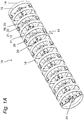
- FIGS. 1A to 1C show, with the Figure 1A which shows about an approximately horizontal axis of rotation rotatable packer roller 10 in a perspective view, the FIG. 1B shows the packer roller 10 in a side view and the Figure 1C shows the packer roller 10 in a side view.
- packer rollers 10 are used, inter alia, in agricultural machines such as. Tillage equipment and seeders use, and are used in particular for reconsolidation of a previously loosened soil and to produce a fine crumbly soil structure, but also for depth control of the agricultural machine.
- the packer roller 10 initially has a rotatable carrier shaft 11 or a carrier profile 12, which in the exemplary embodiment of the FIGS. 1 is designed as a square hollow profile, in which case other cross sections and carrier profile contours would be conceivable.
- At least two opposing spring elements 14 are attached (see the FIG. 1B ), wherein the at least two opposite spring elements 14 in this case form an at least substantially circular or a circular running surface 16 or a packer ring 16.
- the at least two opposite spring elements 14 in this case form an at least substantially circular or a circular running surface 16 or a packer ring 16.
- the carrier shaft 11 or the support section 12 a total of in the longitudinal direction of the support shaft 11 and the carrier profile 12 of the packer roller 10 (spaced by the distances A) spaced spring elements 14 with each ring segmentförmigem rim portion 15, wherein in each case at least two in approximately the same axial position on the support shaft 11 and the carrier profile 12 opposite arranged spring elements 14 together with their adjoining ring segment-shaped rim portions 15 together form a circular or approximately circular tread 16.
- the spring elements 14 each have a hub region 19, two spoke sections 21 and the annular segment-shaped rim section 15, wherein the annular segment-shaped rim sections 15 form an outer, substantially circular or circular segment-shaped peripheral surface 18.
- the hub portion 19 is formed by two inner, with the contour of the support shaft 11 and the support section 12 at least partially corresponding mounting surfaces 20.
- the spoke sections 21 are formed by two connecting surfaces or connecting sections 22 extending between the outer circumferential surface 18 and the rim section 15 and the inner mounting surface 20 and the hub region 19, respectively.
- the mounting surfaces 20 in the hub region 19 each have at least one bore or cutout, by means of which the at least two spring elements 14 can be attached to the carrier shaft 11 or to the carrier profile 12; Furthermore, it can be seen that at least one mounting element 26 is connected to the carrier shaft 11 or the carrier profile 12 and at least one spring element 14.
- the connecting surfaces or spoke sections 21 or connecting sections 22 each have at least one additional connection point 28, by means of which two opposite spring elements 14 fixed to each other and / or are screwed together.
- the side view of Figure 1C clearly shows that the spring elements 14 each have an outer substantially circular peripheral surface 18 which is formed by the circumferentially adjoining annular segment-shaped rim portions 15.
- the spring elements 14 have two inner, at least partially corresponding to the contour of the support section 12 mounting surfaces 20 and two between the outer peripheral surface 18 and the inner mounting surface 20 each extending connecting surfaces or connecting portions 22, as already explained in detail above.
- the carrier profile 12 is assigned in each case a bearing flange 24, by means of which the packer roller 10, for example, is rotatably mountable on a frame construction, not shown here, of an agricultural machine.
- the bearing flange 24 can in this case be welded to both the carrier profile 12 or the carrier shaft 11 as well as screwed but also be connected in other ways with this.
- the bearing flange 24 also has a round inner cross-section in order to simplify, for example, the mounting of a bearing.
- the mounting surfaces 20 in the hub portion 19 each holes or cutouts or the like.
- screws 26 In addition to the use of screws 26 as a mounting member 26 would be other mounting elements 26, such as rivets, bolts or the like. Conceivable, but screws 26 and releasable mounting elements 26 are preferably used, thus easy and quick installation or change of To allow defective spring elements 14, and to keep the overall assembly effort as low as possible.
- At least one additional connection or an additional connection point 28 for example, in the form of a bore 28 or an opening or the like. Cutout in the connecting surfaces or connecting portions 22 - formed by the above spoke sections 21 - attached, whereby the two opposite connecting surfaces or connecting portions 22 or spoke sections 21 in addition to be connected.
- the at least one additional connection point 28 or the additional bore 28 is arranged in a region which is within the outer diameter B of the circumferential surface 18 and outside or equal to half the outer diameter C of the peripheral surface 18th is.
- the additional connection is arranged in a region which is within or equal to half the outer diameter C of the circumferential surface 18. It would also be conceivable to have two or more additional connecting points 28 in the at least two opposite spring elements 14, wherein the positions are each chosen such that a gaping apart of the opposing spring elements 14 can be prevented.
- screws as connecting elements would be for connecting the connecting surfaces on the spoke portions 21 of the respective spring elements 14 and at the connecting portions 22 and other connecting elements, such as rivets, bolts or the like conceivable, but screws or releasable mounting elements preferably use find, so as to allow a simple and quick installation or changeability of defective spring elements 14.
- the circular running surfaces or packer rings 16 which each form at least two opposing spring elements 14, are each arranged rotated by 90 ° radially relative to one another.
- the respective semicircular rim portions 15 are meant, which together form a packer ring 16 when spring elements 14 are joined together.
- This 90 ° offset of respectively adjacent packer rings 16 offers the advantage that despite the circular running surface 16 interrupted by the at least two opposing spring elements 14 smooth-running packer roller 10 is created, since the broken running surface 16 is bridged in each case by the radially rotated to this arranged running surface 16.
- the stability of the packer roller 10 and the spring elements 14 can be substantially increased, since a peripheral surface 18 is supported in each case by one or two adjacent to this arranged and connected connecting surfaces or connecting portions 22 (spoke portions 21).
- the respective angle, by which the spring elements 14 are rotated relative to one another, can thus be, for example, dependent on the number of spring elements 14 forming respectively opposite and a running surface 16.
- a radial rotation also in turn depend on the carrier profile 12, this example. As in the embodiment of FIGS. 1 designed as a square hollow profile, a rotation of 90 ° is optimal, or simplest to perform, since thus no separate or differently designed spring elements 14 are required.
- the peripheral surface 18 and the spring element 14 according to the FIGS. 1A to 1C has on the outside a flat contour, with other contours, such as. V-shaped, U-shaped, T-shaped or the like., Are conceivable or conceivable. It would also be conceivable to provide only individual surfaces with an impressed contour. Thus, it would be conceivable that, for example, the circumferential surface 18 and the mounting surfaces 20 have a flat contour and the connecting surfaces or connecting portions 22 have, for example, a square or triangular or the like contour. Circular pronounced contours would be conceivable.
- connection surface or of the connection section 22 Such contours in the region of the connection surface or of the connection section 22 would have the advantage that a quadratic contour or the like arises through the connection of the at least two opposing spring elements 14 in the region of the connection surfaces or the connection section 22, whereby the stability or the Strength of the packer roller 10 and the spring elements 14 can be further improved.
- the spring elements 14 are each designed so that they can be grown at any point. So that, for example, a packer ring 16 is formed by two opposite and mutually twisted, identical spring elements 14. In this case, only two different components (spring element 14 and carrier profile 12) are required to create a packer roller 10, which in turn are connected by means of connecting elements or mounting elements, in particular in the form of screws.
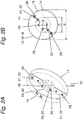
- FIGS. 2A and 2B Further details of at least two opposing spring elements 14 go out of the FIGS. 2A and 2B out.
- Two opposing spring elements 14 which can be mounted on a carrier profile not shown here each form a packer ring or a circular tread 16.
- the spring elements 14 each have an outer substantially circular peripheral surface 18, two inner mounting surfaces 20 corresponding at least in sections to the contour of the carrier profile 12, and two connecting surfaces 22 extending between the outer peripheral surface 18 and the inner mounting surface 20, respectively.
- the at least one additional connection point 28 is arranged in a region which lies within the outer diameter B of the circumferential surface 18 and which is outside or equal to half the outer diameter C of the peripheral surface 18. It would also be conceivable that the at least one additional connection point 28 is arranged in a region which is within or equal to half the outer diameter C of the circumferential surface 18.
- two opposite spring elements 14 are in the embodiment of FIG. 2 by means of at least two by the non-illustrated support profile projecting or plugged through mounting elements 26 in the form of screws 26 connected to the carrier profile, which can also be done by means of one or more screws 26 and wherein other mounting elements can be used. Since the screws 26 and the mounting elements 26 are respectively inserted or passed through a center of the carrier profile, the screws 26 are axially offset from each other. However, it would also be conceivable to arrange the screws 26 outside the center of the carrier profile 12, wherein in this case can be dispensed with an axial offset.
- carrier profiles 12 and attached to these spring elements 14 to provide a packer roller 10 go out of the FIGS. 3A to 3F out.
- the schematic side view of a packer ring 16 of FIG. 3A shows a carrier profile 12, which was made of a tube profile.
- Two opposing spring elements 14 are respectively arranged on this tube by means of mounting elements 26 in the form of screws such that their ring-segment-shaped rim sections 15 or their peripheral surfaces 18 form a circular running surface 16 or a packer ring 16.
- the spring elements 14 each have an outer substantially circular peripheral surface 18, two inner mounting surfaces 20 corresponding at least in sections to the contour of the carrier profile 12 in their hub region 19, and two connecting surfaces or connecting sections 22 respectively extending between the outer circumferential surface 18 and the inner mounting surface 20 formed by the spoke sections 21 so designated here.
- the mounting surface 20 in the hub region 19 of the spring elements 14 is in the embodiment of FIG.
- FIG. 3B The schematic side view of a packer ring 16 of FIG. 3B shows an alternatively shaped support section 12 and an alternatively shaped support shaft 11, which is composed of two profile halves, for example, in the form of sheet metal halves, wherein the support section 12 has a square cross section in a central region, which merges in the radial direction outwards into a flat cross section.
- carrier profile 12 On carrier profile 12, in each case by means of mounting elements 26 in the form of screws, two opposing spring elements 14 are arranged with their hub region 19 such that their peripheral surfaces 18 form a circular running surface 16 or a packer ring 16.
- these mounting elements 26 and the two profile halves can be connected, which can also be welded or connected by means of other mounting means.
- the spring elements 12 each have an outer substantially circular peripheral surface 18, two inner mounting surfaces 20 corresponding at least in sections to the contour of the carrier profile 12, and two connecting surfaces or connecting sections 22 extending between the outer circumferential surface 18 and the inner mounting surface 20, respectively.
- at least one additional connection point 28 or an additional bore 28 in FIG the connecting surfaces or connecting portions 22 are additionally connected to the spoke portions 21, whereby the two opposite connecting surfaces or connecting portions 22 and spoke sections 21 are additionally connected.
- the spring elements 14 are connected by means of the connection point 28 once more firmly connected to the carrier profile 12, whereby the strength of the packer roller 10 and the spring elements 14 can be further increased.
- FIG. 3C shows a further carrier profile 12, which is composed of a flat material and one or two angular materials, wherein the carrier profile 12 in a central region has a square cross-section which merges in the radial direction outwards into a flat cross-section.
- carrier profile 12 two opposing spring elements 14 are respectively arranged in such a way by means of mounting elements 26 in the form of screws, that their peripheral surfaces 18 form a circular running surface 16 or a packer ring.
- the spring elements 12 each have an outer substantially circular Peripheral surface 18, two inner contour of the support profile 12 at least partially corresponding mounting surfaces 20 and two between the outer peripheral surface 18 and the inner mounting surface 20 each extending connecting surfaces or connecting portions 22.
- the Figure 3D shows a support section 12, which consists of a tubular profile and each offset by 90 ° to each other mounted flat materials, wherein the support section 12 in a central region has a round cross-section which merges in the radial direction outwards into a flat cross-section.
- carrier profile 12 two opposing spring elements 14 are arranged in each case by means of mounting elements 26 in the form of screws such that their peripheral surfaces 18 form a circular running surface 16 or a packer ring 16.
- the spring elements 14 each have an outer substantially circular peripheral surface 18, two inner mounting surfaces 20 corresponding at least in sections to the contour of the carrier profile 12, and two connecting surfaces or connecting sections 22 each extending between the outer peripheral surface 18 and the inner mounting surface 20.
- FIG. 3E shows a carrier profile 12, which is composed of two angle profiles, which are each rotated by 180 ° to each other.
- carrier profile 12 two opposing spring elements 14 are each arranged by means of mounting elements 26 in the form of screws such that their peripheral surfaces 18 a circular Tread 16 and a packer ring 16 form.
- the spring elements 12 each have an outer substantially circular peripheral surface 18, two inner the contour of the support section 12 at least partially corresponding mounting surfaces 20 and two between the outer peripheral surface 18 and the inner mounting surface 20 each extending connecting surfaces or connecting portions 22, wherein each one Mounting surface 20 and a connecting surface or a connecting portion 22 are formed by a common portion of the spring element 14.
- the spring elements 14 are again connected by means of the connection point 28 with the carrier profile 12, whereby the strength of the packer roller 10 and the spring elements 14 can be further increased.
- FIG. 3F shows a carrier profile 12, which is composed of two or three flat materials, which are each arranged rotated by 90 ° to each other.
- carrier profile 12 two opposing spring elements 14 are arranged in each case by means of mounting elements 26 in the form of screws such that their peripheral surfaces 18 form a circular running surface 16 or a packer ring 16.
- the spring elements 14 in this case each have an outer substantially circular peripheral surface 18, two inner the contour of the support section 12 at least partially corresponding mounting surfaces 20 and two between the outer peripheral surface 18 and the inner mounting surface 20 each extending connecting surfaces or connecting portions 22, respectively a mounting surface 20 and a connecting surface or a connecting portion 22 are formed by a common portion of the spring element 14.
- the spring elements 14 are again connected by means of the connection point 28 with the carrier profile 12, whereby the strength of the packer roller 10 and the spring elements 14 can be further increased.
Landscapes
- Life Sciences & Earth Sciences (AREA)
- Engineering & Computer Science (AREA)
- Mechanical Engineering (AREA)
- Soil Sciences (AREA)
- Environmental Sciences (AREA)
- Soil Working Implements (AREA)
- Tires In General (AREA)
Applications Claiming Priority (1)
| Application Number | Priority Date | Filing Date | Title |
|---|---|---|---|
| DE102017105403.0A DE102017105403A1 (de) | 2017-03-14 | 2017-03-14 | Packerwalze zur Bodenbearbeitung |
Publications (2)
| Publication Number | Publication Date |
|---|---|
| EP3375272A1 true EP3375272A1 (fr) | 2018-09-19 |
| EP3375272B1 EP3375272B1 (fr) | 2020-08-05 |
Family
ID=61627014
Family Applications (1)
| Application Number | Title | Priority Date | Filing Date |
|---|---|---|---|
| EP18161333.2A Active EP3375272B1 (fr) | 2017-03-14 | 2018-03-12 | Rouleaux de compactage pour le travail du sol |
Country Status (2)
| Country | Link |
|---|---|
| EP (1) | EP3375272B1 (fr) |
| DE (1) | DE102017105403A1 (fr) |
Families Citing this family (3)
| Publication number | Priority date | Publication date | Assignee | Title |
|---|---|---|---|---|
| DE102017220113A1 (de) | 2017-11-10 | 2019-05-16 | Horsch Maschinen Gmbh | Säschar einer landwirtschaftlichen Maschine mit zugehörigem Tiefenführungsrad |
| DE102022104961A1 (de) * | 2022-03-02 | 2023-09-07 | Lemken Gmbh & Co. Kg | Bodenbearbeitungsgerät |
| DE202022104096U1 (de) | 2022-07-20 | 2023-10-23 | Konrad Hendlmeier | Tragvorrichtung für Bodenbearbeitungswerkzeuge einer Bodenbearbeitungsvorrichtung sowie Bodenbearbeitungsvorrichtung |
Citations (7)
| Publication number | Priority date | Publication date | Assignee | Title |
|---|---|---|---|---|
| EP0998185B1 (fr) * | 1997-06-18 | 2005-03-02 | Konrad Hendlmeier | Dispositif permettant de combiner la preparation du sol pour les semailles et l'epandage de la semence |
| EP2177098A1 (fr) * | 2008-10-16 | 2010-04-21 | Konrad Hendlmeier | Dispositif de préparation du sol pour semer et distribuer des semences |
| EP2386196A1 (fr) * | 2010-05-11 | 2011-11-16 | Amazonen-Werke H. Dreyer GmbH & Co. KG | Dispositif agricole pour compacter le sol |
| WO2012060770A1 (fr) * | 2010-11-01 | 2012-05-10 | Väderstad-Verken Ab | Cylindre rouleau et segment d'anneau de ruban destiné à celui-ci |
| EP2433481B1 (fr) * | 2010-09-22 | 2014-12-31 | Konrad Hendlmeier | Dispositif en forme de cylindre pour le traitement du sol |
| DE202013009670U1 (de) * | 2013-10-31 | 2015-02-03 | Alois Pöttinger Maschinenfabrik Ges.m.b.H. | Landwirtschaftliche Bodenwalze |
| WO2017188885A1 (fr) * | 2016-04-29 | 2017-11-02 | Väderstad Holding Ab | Segment de rouleau, roue à rouleau et outil agricole comprenant un tel rouleau |
-
2017
- 2017-03-14 DE DE102017105403.0A patent/DE102017105403A1/de active Pending
-
2018
- 2018-03-12 EP EP18161333.2A patent/EP3375272B1/fr active Active
Patent Citations (7)
| Publication number | Priority date | Publication date | Assignee | Title |
|---|---|---|---|---|
| EP0998185B1 (fr) * | 1997-06-18 | 2005-03-02 | Konrad Hendlmeier | Dispositif permettant de combiner la preparation du sol pour les semailles et l'epandage de la semence |
| EP2177098A1 (fr) * | 2008-10-16 | 2010-04-21 | Konrad Hendlmeier | Dispositif de préparation du sol pour semer et distribuer des semences |
| EP2386196A1 (fr) * | 2010-05-11 | 2011-11-16 | Amazonen-Werke H. Dreyer GmbH & Co. KG | Dispositif agricole pour compacter le sol |
| EP2433481B1 (fr) * | 2010-09-22 | 2014-12-31 | Konrad Hendlmeier | Dispositif en forme de cylindre pour le traitement du sol |
| WO2012060770A1 (fr) * | 2010-11-01 | 2012-05-10 | Väderstad-Verken Ab | Cylindre rouleau et segment d'anneau de ruban destiné à celui-ci |
| DE202013009670U1 (de) * | 2013-10-31 | 2015-02-03 | Alois Pöttinger Maschinenfabrik Ges.m.b.H. | Landwirtschaftliche Bodenwalze |
| WO2017188885A1 (fr) * | 2016-04-29 | 2017-11-02 | Väderstad Holding Ab | Segment de rouleau, roue à rouleau et outil agricole comprenant un tel rouleau |
Also Published As
| Publication number | Publication date |
|---|---|
| DE102017105403A1 (de) | 2018-09-20 |
| EP3375272B1 (fr) | 2020-08-05 |
Similar Documents
| Publication | Publication Date | Title |
|---|---|---|
| DE102014111295B4 (de) | Packerwalze und Verfahren zum Umrüsten derselben für unterschiedliche Bodenbearbeitungsmodi | |
| EP1983817B1 (fr) | Outil agricole rotatif avec agencement de palier | |
| EP2433481B1 (fr) | Dispositif en forme de cylindre pour le traitement du sol | |
| EP3375272B1 (fr) | Rouleaux de compactage pour le travail du sol | |
| EP2807910B1 (fr) | Porte-outil avec liaison soudée | |
| EP0133710A2 (fr) | Rouleau sous-sol, compacteur | |
| EP3649841B1 (fr) | Machine agricole destinée au traitement du sol | |
| DE102014201519B4 (de) | Mähgerat | |
| EP3158841B1 (fr) | Rouleau agricole | |
| DE102016107948A1 (de) | Lageranordnung einer landwirtschaftlichen Maschine | |
| DE2734437C2 (de) | Krümelwalze für Bodenbearbeitungsmaschinen | |
| EP2177098A1 (fr) | Dispositif de préparation du sol pour semer et distribuer des semences | |
| DE3324157C2 (de) | Packer oder walzenförmiges Bodenbearbeitungsgerät | |
| EP3831176B1 (fr) | Dispositif de suspension | |
| EP2965602B1 (fr) | Semoir | |
| EP4280855A1 (fr) | Couronne de rouleau pour un corps de rouleau d'un dispositif de travail du sol | |
| EP4140267B1 (fr) | Rouleau de sol pour une machine de travail du sol agricole | |
| DE10338864B4 (de) | Haspel | |
| EP4486105B1 (fr) | Appareil de travail du sol | |
| DE4018366C2 (de) | Boden- oder Packerwalze | |
| DE69519249T2 (de) | Landwirtschaftliche Bodenbearbeitungswalze und Landmaschine mit einer solchen Walze | |
| CH711705B1 (de) | Vorrichtung zum lösbaren Verbinden einer Zusatzradfelge mit einer Fahrzeugradfelge und Anordnung aus einer Fahrzeugradfelge, einer Zusatzradfelge und einer solchen Vorrichtung. | |
| WO2019206508A1 (fr) | Élément de palier et ensemble palier d'une machine agricole | |
| DE102009040302B4 (de) | Exzenterlager | |
| DE2803893A1 (de) | Landwirtschaftliche bodenbearbeitungsmaschine |
Legal Events
| Date | Code | Title | Description |
|---|---|---|---|
| PUAI | Public reference made under article 153(3) epc to a published international application that has entered the european phase |
Free format text: ORIGINAL CODE: 0009012 |
|
| STAA | Information on the status of an ep patent application or granted ep patent |
Free format text: STATUS: THE APPLICATION HAS BEEN PUBLISHED |
|
| AK | Designated contracting states |
Kind code of ref document: A1 Designated state(s): AL AT BE BG CH CY CZ DE DK EE ES FI FR GB GR HR HU IE IS IT LI LT LU LV MC MK MT NL NO PL PT RO RS SE SI SK SM TR |
|
| AX | Request for extension of the european patent |
Extension state: BA ME |
|
| STAA | Information on the status of an ep patent application or granted ep patent |
Free format text: STATUS: REQUEST FOR EXAMINATION WAS MADE |
|
| 17P | Request for examination filed |
Effective date: 20190313 |
|
| RBV | Designated contracting states (corrected) |
Designated state(s): AL AT BE BG CH CY CZ DE DK EE ES FI FR GB GR HR HU IE IS IT LI LT LU LV MC MK MT NL NO PL PT RO RS SE SI SK SM TR |
|
| STAA | Information on the status of an ep patent application or granted ep patent |
Free format text: STATUS: EXAMINATION IS IN PROGRESS |
|
| 17Q | First examination report despatched |
Effective date: 20191004 |
|
| GRAP | Despatch of communication of intention to grant a patent |
Free format text: ORIGINAL CODE: EPIDOSNIGR1 |
|
| STAA | Information on the status of an ep patent application or granted ep patent |
Free format text: STATUS: GRANT OF PATENT IS INTENDED |
|
| INTG | Intention to grant announced |
Effective date: 20200305 |
|
| GRAS | Grant fee paid |
Free format text: ORIGINAL CODE: EPIDOSNIGR3 |
|
| GRAA | (expected) grant |
Free format text: ORIGINAL CODE: 0009210 |
|
| STAA | Information on the status of an ep patent application or granted ep patent |
Free format text: STATUS: THE PATENT HAS BEEN GRANTED |
|
| AK | Designated contracting states |
Kind code of ref document: B1 Designated state(s): AL AT BE BG CH CY CZ DE DK EE ES FI FR GB GR HR HU IE IS IT LI LT LU LV MC MK MT NL NO PL PT RO RS SE SI SK SM TR |
|
| REG | Reference to a national code |
Ref country code: GB Ref legal event code: FG4D Free format text: NOT ENGLISH |
|
| REG | Reference to a national code |
Ref country code: CH Ref legal event code: EP |
|
| REG | Reference to a national code |
Ref country code: AT Ref legal event code: REF Ref document number: 1297383 Country of ref document: AT Kind code of ref document: T Effective date: 20200815 |
|
| REG | Reference to a national code |
Ref country code: DE Ref legal event code: R096 Ref document number: 502018002053 Country of ref document: DE |
|
| REG | Reference to a national code |
Ref country code: IE Ref legal event code: FG4D Free format text: LANGUAGE OF EP DOCUMENT: GERMAN |
|
| REG | Reference to a national code |
Ref country code: SE Ref legal event code: TRGR |
|
| REG | Reference to a national code |
Ref country code: LT Ref legal event code: MG4D |
|
| REG | Reference to a national code |
Ref country code: NL Ref legal event code: MP Effective date: 20200805 |
|
| PG25 | Lapsed in a contracting state [announced via postgrant information from national office to epo] |
Ref country code: BG Free format text: LAPSE BECAUSE OF FAILURE TO SUBMIT A TRANSLATION OF THE DESCRIPTION OR TO PAY THE FEE WITHIN THE PRESCRIBED TIME-LIMIT Effective date: 20201105 Ref country code: NO Free format text: LAPSE BECAUSE OF FAILURE TO SUBMIT A TRANSLATION OF THE DESCRIPTION OR TO PAY THE FEE WITHIN THE PRESCRIBED TIME-LIMIT Effective date: 20201105 Ref country code: LT Free format text: LAPSE BECAUSE OF FAILURE TO SUBMIT A TRANSLATION OF THE DESCRIPTION OR TO PAY THE FEE WITHIN THE PRESCRIBED TIME-LIMIT Effective date: 20200805 Ref country code: HR Free format text: LAPSE BECAUSE OF FAILURE TO SUBMIT A TRANSLATION OF THE DESCRIPTION OR TO PAY THE FEE WITHIN THE PRESCRIBED TIME-LIMIT Effective date: 20200805 Ref country code: PT Free format text: LAPSE BECAUSE OF FAILURE TO SUBMIT A TRANSLATION OF THE DESCRIPTION OR TO PAY THE FEE WITHIN THE PRESCRIBED TIME-LIMIT Effective date: 20201207 Ref country code: ES Free format text: LAPSE BECAUSE OF FAILURE TO SUBMIT A TRANSLATION OF THE DESCRIPTION OR TO PAY THE FEE WITHIN THE PRESCRIBED TIME-LIMIT Effective date: 20200805 Ref country code: FI Free format text: LAPSE BECAUSE OF FAILURE TO SUBMIT A TRANSLATION OF THE DESCRIPTION OR TO PAY THE FEE WITHIN THE PRESCRIBED TIME-LIMIT Effective date: 20200805 Ref country code: GR Free format text: LAPSE BECAUSE OF FAILURE TO SUBMIT A TRANSLATION OF THE DESCRIPTION OR TO PAY THE FEE WITHIN THE PRESCRIBED TIME-LIMIT Effective date: 20201106 |
|
| PG25 | Lapsed in a contracting state [announced via postgrant information from national office to epo] |
Ref country code: LV Free format text: LAPSE BECAUSE OF FAILURE TO SUBMIT A TRANSLATION OF THE DESCRIPTION OR TO PAY THE FEE WITHIN THE PRESCRIBED TIME-LIMIT Effective date: 20200805 Ref country code: NL Free format text: LAPSE BECAUSE OF FAILURE TO SUBMIT A TRANSLATION OF THE DESCRIPTION OR TO PAY THE FEE WITHIN THE PRESCRIBED TIME-LIMIT Effective date: 20200805 Ref country code: RS Free format text: LAPSE BECAUSE OF FAILURE TO SUBMIT A TRANSLATION OF THE DESCRIPTION OR TO PAY THE FEE WITHIN THE PRESCRIBED TIME-LIMIT Effective date: 20200805 Ref country code: PL Free format text: LAPSE BECAUSE OF FAILURE TO SUBMIT A TRANSLATION OF THE DESCRIPTION OR TO PAY THE FEE WITHIN THE PRESCRIBED TIME-LIMIT Effective date: 20200805 Ref country code: IS Free format text: LAPSE BECAUSE OF FAILURE TO SUBMIT A TRANSLATION OF THE DESCRIPTION OR TO PAY THE FEE WITHIN THE PRESCRIBED TIME-LIMIT Effective date: 20201205 |
|
| PG25 | Lapsed in a contracting state [announced via postgrant information from national office to epo] |
Ref country code: RO Free format text: LAPSE BECAUSE OF FAILURE TO SUBMIT A TRANSLATION OF THE DESCRIPTION OR TO PAY THE FEE WITHIN THE PRESCRIBED TIME-LIMIT Effective date: 20200805 Ref country code: DK Free format text: LAPSE BECAUSE OF FAILURE TO SUBMIT A TRANSLATION OF THE DESCRIPTION OR TO PAY THE FEE WITHIN THE PRESCRIBED TIME-LIMIT Effective date: 20200805 Ref country code: EE Free format text: LAPSE BECAUSE OF FAILURE TO SUBMIT A TRANSLATION OF THE DESCRIPTION OR TO PAY THE FEE WITHIN THE PRESCRIBED TIME-LIMIT Effective date: 20200805 Ref country code: SM Free format text: LAPSE BECAUSE OF FAILURE TO SUBMIT A TRANSLATION OF THE DESCRIPTION OR TO PAY THE FEE WITHIN THE PRESCRIBED TIME-LIMIT Effective date: 20200805 |
|
| REG | Reference to a national code |
Ref country code: DE Ref legal event code: R097 Ref document number: 502018002053 Country of ref document: DE |
|
| PG25 | Lapsed in a contracting state [announced via postgrant information from national office to epo] |
Ref country code: AL Free format text: LAPSE BECAUSE OF FAILURE TO SUBMIT A TRANSLATION OF THE DESCRIPTION OR TO PAY THE FEE WITHIN THE PRESCRIBED TIME-LIMIT Effective date: 20200805 |
|
| PLBE | No opposition filed within time limit |
Free format text: ORIGINAL CODE: 0009261 |
|
| STAA | Information on the status of an ep patent application or granted ep patent |
Free format text: STATUS: NO OPPOSITION FILED WITHIN TIME LIMIT |
|
| PG25 | Lapsed in a contracting state [announced via postgrant information from national office to epo] |
Ref country code: SK Free format text: LAPSE BECAUSE OF FAILURE TO SUBMIT A TRANSLATION OF THE DESCRIPTION OR TO PAY THE FEE WITHIN THE PRESCRIBED TIME-LIMIT Effective date: 20200805 |
|
| 26N | No opposition filed |
Effective date: 20210507 |
|
| PG25 | Lapsed in a contracting state [announced via postgrant information from national office to epo] |
Ref country code: IT Free format text: LAPSE BECAUSE OF FAILURE TO SUBMIT A TRANSLATION OF THE DESCRIPTION OR TO PAY THE FEE WITHIN THE PRESCRIBED TIME-LIMIT Effective date: 20200805 |
|
| PG25 | Lapsed in a contracting state [announced via postgrant information from national office to epo] |
Ref country code: SI Free format text: LAPSE BECAUSE OF FAILURE TO SUBMIT A TRANSLATION OF THE DESCRIPTION OR TO PAY THE FEE WITHIN THE PRESCRIBED TIME-LIMIT Effective date: 20200805 |
|
| PG25 | Lapsed in a contracting state [announced via postgrant information from national office to epo] |
Ref country code: MC Free format text: LAPSE BECAUSE OF FAILURE TO SUBMIT A TRANSLATION OF THE DESCRIPTION OR TO PAY THE FEE WITHIN THE PRESCRIBED TIME-LIMIT Effective date: 20200805 |
|
| REG | Reference to a national code |
Ref country code: CH Ref legal event code: PL |
|
| REG | Reference to a national code |
Ref country code: BE Ref legal event code: MM Effective date: 20210331 |
|
| PG25 | Lapsed in a contracting state [announced via postgrant information from national office to epo] |
Ref country code: IE Free format text: LAPSE BECAUSE OF NON-PAYMENT OF DUE FEES Effective date: 20210312 Ref country code: LI Free format text: LAPSE BECAUSE OF NON-PAYMENT OF DUE FEES Effective date: 20210331 Ref country code: LU Free format text: LAPSE BECAUSE OF NON-PAYMENT OF DUE FEES Effective date: 20210312 Ref country code: CH Free format text: LAPSE BECAUSE OF NON-PAYMENT OF DUE FEES Effective date: 20210331 |
|
| PG25 | Lapsed in a contracting state [announced via postgrant information from national office to epo] |
Ref country code: BE Free format text: LAPSE BECAUSE OF NON-PAYMENT OF DUE FEES Effective date: 20210331 |
|
| GBPC | Gb: european patent ceased through non-payment of renewal fee |
Effective date: 20220312 |
|
| PG25 | Lapsed in a contracting state [announced via postgrant information from national office to epo] |
Ref country code: GB Free format text: LAPSE BECAUSE OF NON-PAYMENT OF DUE FEES Effective date: 20220312 |
|
| PG25 | Lapsed in a contracting state [announced via postgrant information from national office to epo] |
Ref country code: CY Free format text: LAPSE BECAUSE OF FAILURE TO SUBMIT A TRANSLATION OF THE DESCRIPTION OR TO PAY THE FEE WITHIN THE PRESCRIBED TIME-LIMIT Effective date: 20200805 |
|
| PG25 | Lapsed in a contracting state [announced via postgrant information from national office to epo] |
Ref country code: HU Free format text: LAPSE BECAUSE OF FAILURE TO SUBMIT A TRANSLATION OF THE DESCRIPTION OR TO PAY THE FEE WITHIN THE PRESCRIBED TIME-LIMIT; INVALID AB INITIO Effective date: 20180312 |
|
| PG25 | Lapsed in a contracting state [announced via postgrant information from national office to epo] |
Ref country code: MK Free format text: LAPSE BECAUSE OF FAILURE TO SUBMIT A TRANSLATION OF THE DESCRIPTION OR TO PAY THE FEE WITHIN THE PRESCRIBED TIME-LIMIT Effective date: 20200805 |
|
| REG | Reference to a national code |
Ref country code: AT Ref legal event code: MM01 Ref document number: 1297383 Country of ref document: AT Kind code of ref document: T Effective date: 20230312 |
|
| PG25 | Lapsed in a contracting state [announced via postgrant information from national office to epo] |
Ref country code: TR Free format text: LAPSE BECAUSE OF FAILURE TO SUBMIT A TRANSLATION OF THE DESCRIPTION OR TO PAY THE FEE WITHIN THE PRESCRIBED TIME-LIMIT Effective date: 20200805 |
|
| PG25 | Lapsed in a contracting state [announced via postgrant information from national office to epo] |
Ref country code: AT Free format text: LAPSE BECAUSE OF NON-PAYMENT OF DUE FEES Effective date: 20230312 |
|
| PG25 | Lapsed in a contracting state [announced via postgrant information from national office to epo] |
Ref country code: AT Free format text: LAPSE BECAUSE OF NON-PAYMENT OF DUE FEES Effective date: 20230312 |
|
| PG25 | Lapsed in a contracting state [announced via postgrant information from national office to epo] |
Ref country code: MT Free format text: LAPSE BECAUSE OF FAILURE TO SUBMIT A TRANSLATION OF THE DESCRIPTION OR TO PAY THE FEE WITHIN THE PRESCRIBED TIME-LIMIT Effective date: 20200805 |
|
| REG | Reference to a national code |
Ref country code: DE Ref legal event code: R082 Ref document number: 502018002053 Country of ref document: DE Representative=s name: BENNINGER, JOHANNES, DIPL.-ING., DE |
|
| PGFP | Annual fee paid to national office [announced via postgrant information from national office to epo] |
Ref country code: SE Payment date: 20260323 Year of fee payment: 9 |
|
| PGFP | Annual fee paid to national office [announced via postgrant information from national office to epo] |
Ref country code: DE Payment date: 20260320 Year of fee payment: 9 |
|
| PGFP | Annual fee paid to national office [announced via postgrant information from national office to epo] |
Ref country code: AT Payment date: 20260410 Year of fee payment: 5 |
|
| PGFP | Annual fee paid to national office [announced via postgrant information from national office to epo] |
Ref country code: FR Payment date: 20260325 Year of fee payment: 9 |
|
| PGFP | Annual fee paid to national office [announced via postgrant information from national office to epo] |
Ref country code: CZ Payment date: 20260227 Year of fee payment: 9 |
|
| REG | Reference to a national code |
Ref country code: DE Ref legal event code: R081 Ref document number: 502018002053 Country of ref document: DE Owner name: HORSCH MASCHINEN SE & CO. KG, DE Free format text: FORMER OWNER: HORSCH MASCHINEN GMBH, 92421 SCHWANDORF, DE |