EP3375408B1 - Zahnärztliche lichtpolymerisierungsvorrichtung - Google Patents
Zahnärztliche lichtpolymerisierungsvorrichtung Download PDFInfo
- Publication number
- EP3375408B1 EP3375408B1 EP17160707.0A EP17160707A EP3375408B1 EP 3375408 B1 EP3375408 B1 EP 3375408B1 EP 17160707 A EP17160707 A EP 17160707A EP 3375408 B1 EP3375408 B1 EP 3375408B1
- Authority
- EP
- European Patent Office
- Prior art keywords
- housing
- polymerization device
- light polymerization
- receiver
- dental light
- Prior art date
- Legal status (The legal status is an assumption and is not a legal conclusion. Google has not performed a legal analysis and makes no representation as to the accuracy of the status listed.)
- Active
Links
- 238000006116 polymerization reaction Methods 0.000 title claims description 76
- 230000005284 excitation Effects 0.000 claims description 36
- 238000005286 illumination Methods 0.000 claims description 3
- 230000003287 optical effect Effects 0.000 claims description 3
- 239000000463 material Substances 0.000 description 9
- 239000005548 dental material Substances 0.000 description 4
- 238000010586 diagram Methods 0.000 description 4
- 238000004140 cleaning Methods 0.000 description 3
- 238000011156 evaluation Methods 0.000 description 3
- 230000004913 activation Effects 0.000 description 2
- 239000012459 cleaning agent Substances 0.000 description 2
- 239000000645 desinfectant Substances 0.000 description 2
- 239000011159 matrix material Substances 0.000 description 2
- 238000004659 sterilization and disinfection Methods 0.000 description 2
- XLYOFNOQVPJJNP-UHFFFAOYSA-N water Substances O XLYOFNOQVPJJNP-UHFFFAOYSA-N 0.000 description 2
- 238000010521 absorption reaction Methods 0.000 description 1
- 239000003086 colorant Substances 0.000 description 1
- 208000002925 dental caries Diseases 0.000 description 1
- 238000001514 detection method Methods 0.000 description 1
- 239000000945 filler Substances 0.000 description 1
- 230000009969 flowable effect Effects 0.000 description 1
- 239000003365 glass fiber Substances 0.000 description 1
- 230000010355 oscillation Effects 0.000 description 1
- 238000007789 sealing Methods 0.000 description 1
- 238000001228 spectrum Methods 0.000 description 1
- 230000002459 sustained effect Effects 0.000 description 1
Images


Classifications
-
- A—HUMAN NECESSITIES
- A61—MEDICAL OR VETERINARY SCIENCE; HYGIENE
- A61C—DENTISTRY; APPARATUS OR METHODS FOR ORAL OR DENTAL HYGIENE
- A61C19/00—Dental auxiliary appliances
- A61C19/003—Apparatus for curing resins by radiation
- A61C19/004—Hand-held apparatus, e.g. guns
Definitions
- the invention relates to a dental light polymerization device.
- the invention relates to a dental light polymerization device which has a piezoelectric transmitter and at least a piezoelectric first receiver for sensing a user input.
- Light hardenable or light curable materials are widely used in dentistry for the restoration of teeth. Many of such materials are made to provide optical instructions that resemble those of natural teeth. Further such materials typically can be placed precisely and conveniently, can be hardened instantly, and the hardened material is typically relatively durable.
- Light hardenable materials often include a polymerizable matrix material and filler materials including colorants, and may initially be generally soft or flowable so that they can be applied in a desired location and shape.
- the dental material may be filled into a tooth cavity and shaped so that the restored tooth resembles a natural tooth.
- the material may be cured by exposing it to light of a desired wavelength. The light typically activates photoinitiators in the dental material that cause the matrix material to polymerize.
- dental light-emitting devices are provided with one or more buttons for controlling electric functions of the device, for example one or more push buttons for switching the device on and for selecting different modes of operation.
- buttons for controlling electric functions of the device, for example one or more push buttons for switching the device on and for selecting different modes of operation.
- hygiene standards often require materials used for the light-emitting devices to be resistant against aggressive disinfectants and/or cleaning agents.
- US 2011/0300505 A1 discloses a dental polymerisation device with a conventional push button.
- the invention relates to a dental light polymerization device.
- the dental light polymerization device comprises a housing, a light source for emitting blue light, a piezoelectric transmitter and at least a piezoelectric first receiver.
- the transmitter is acoustically coupled with the housing for transmitting an acoustic wave into the housing and the first receiver is acoustically coupled to the housing for picking up the acoustic wave from the housing.
- the transmitter and the first receiver are arranged spaced from each other. A portion of the housing between the transmitter and the first receiver forms a first touch surface.
- the acoustic wave can vary, for example in its amplitude and/or frequency, between the transmitter and the at least first receiver.
- blue light refers to light having a wavelength within the range of about 430 nm to 500 nm, preferably within a range of about 430 nm to 480 nm. Blue light preferably predominantly consists of light within a range of about 430 nm to 480 nm. The blue light may particularly not comprise light having a wavelength outside the range of about 430 nm to 480 nm at a substantial intensity or at all.
- blue light may have a first portion of light within a range of about 430 nm to 480 nm and preferably does not have a significant second light portion within a range of 570 nm and 590 nm, wherein the maximum intensity of the second portion of light is preferably less than 10% and more preferably less than 1% of the maximum intensity of the first portion of light.
- Further blue light may not have a significant third light portion within the spectrum of visible light outside the range of 430 nm and 480 nm and outside the range of 570 nm to 590 nm, wherein the maximum intensity of any third portion of light is preferably less than 25% and more preferably less than 20% of the maximum intensity of the first portion of light.
- the dental light polymerization device comprises at least a piezoelectric second receiver.
- the second receiver is preferably acoustically coupled to the housing for picking up the acoustic wave from the housing.
- the transmitter and the second receiver are preferably arranged spaced from each other.
- a further portion of the housing between the transmitter and the second receiver preferably forms a second touch surface. Further receivers forming further touch surfaces may be present in the dental light polymerization device.
- the transmitter and the first receiver are arranged within the housing.
- the transmitter and the first receiver are encapsulated, preferably hermetically encapsulated within the housing.
- the transmitter and the first and second receiver are preferably arranged within the housing, preferably hermetically encapsulated within the housing.
- the transmitter is arranged between the first and second receiver.
- the transmitter and the first receiver are preferably spaced from each other at the same distance as the transmitter and the second receiver.
- the transmitter and the first and second receiver each comprise a piezoelectric element that is mechanically coupled to the housing.
- the piezoelectric element may be in direct mechanical contact or may be bonded or otherwise mechanically attached to the housing.
- oscillations can be transferred between the transmitter and the housing and between the housing and the first and second receiver.
- the dental light polymerization device further comprises an electrical control circuit.
- the electrical control circuit is (electrically) connected or (electrically) connectable to the transmitter and the first receiver.
- the control unit preferably comprises a signal generator. Further, the control unit is preferably configured to operate the transmitter based on an excitation signal provided by the signal generator for generating the acoustic wave.
- the piezo element of the transmitter may be powered by a voltage that carries or forms the excitation signal provided by the signal generator.
- the control unit is further configured to receive a first and second response signal from the first and second receiver, respectively, based on the acoustic wave picked up by the first and/or second receiver, respectively.
- the piezo element of each of the first and second receiver may generate a voltage in response to the acoustic wave that excites the respective piezo element.
- the control unit is further preferably configured to determine a difference between the excitation signal and the first response signal.
- the control unit may further be configured to determine a difference between the excitation signal and the second response signal. Based on the difference between the excitation signal and the first response signal, the control unit is preferably configured to provide a first control signal that is representative of a presence or absence of a user's finger on the first touch surface.
- the control unit is preferably configured to provide a second control signal that is representative of a presence or absence of a user's finger on the second touch surface.
- the first control signal may be used to activate the dental light polymerization device in a polymerization function. In the polymerization function the light source is activated for a pre-determined or pre-selected time period before the light source is automatically deactivated.
- the second control signal may be used to preselect the time period for which the dental light polymerization device operates in the polymerization function.
- each second control signal causes the pre-selected time period to switch consecutively from 5 seconds, 10 seconds, 15 seconds, 20 seconds, 120 seconds. After 120 seconds the time period starts over from 5 seconds. Other time periods may be provided as appropriate.
- the difference between the excitation and the first response signal comprises a difference between an excitation amplitude of the excitation signal and a first response amplitude of the first response signal.
- the difference between the excitation and the second response signal may comprises a difference between an excitation amplitude of the excitation signal and a second response amplitude of the second response signal.
- a lower first or second response amplitude than the excitation amplitude is indicative of a presence of a user's finger on the first or second touch surface, respectively.
- the housing forms a grip portion of the dental light polymerization device.
- the dental light polymerization device preferably has a tip portion protruding from the grip portion.
- the tip portion at a free end preferably forms a light output from which light generated by the light source is emitted when the light source is activated.
- the tip portion may comprise the light source, for example a high power LED (Light Emitting Diode) or a laser diode.
- the dental light polymerization device further comprises a rechargeable battery that is encapsulated within the housing.
- the dental light polymerization device has no movable actuator, in particular no switch or button, for operating the dental light polymerization device, in particular for operating the electric functions of the dental light polymerization device.
- an indicator function that acknowledges a recognition of a user's finger on the housing.
- the indicator function may comprise at least one of an audible, optical and tactile signal.
- the dental light polymerization device may comprise at least one of a loudspeaker, beeper, indicator lamp or indicator screen or a vibration unit.
- the dental light polymerization device may further have an illumination device arranged in the housing.
- the illumination device may be configured to illuminate the first and/or second touch surface from behind the first and/or second touch surface, respectively.
- Fig. 1 shows a dental light polymerization device 1.
- the dental light polymerization device 1 has a housing 2 that forms a grip portion for manually handling of the dental light polymerization device 1.
- the dental light polymerization device 1 further has a tip portion 3 for intra-oral use.
- the tip portion 3 is an elongated structure a free end 4 of which forms a light output 5.
- a light source (not visible) for emitting blue light is arranged within the free end 4 of the dental light polymerization device 1.
- the light source may be arranged within the housing and the tip portion may be a light guide, for example one that has a plurality of parallel extending glass fibers.
- the light source in the example is a high power LED (Light Emitting Diode), but may in another example comprise any other type of light source, for example a Laser.
- the dental light polymerization device 1 in the example is an overall wireless device, but may in another example be wired.
- the dental light polymerization device 1 has a rechargeable battery (not visible).
- a charging device may be provided (not shown) by which the battery can be charged.
- the dental light polymerization device 1 may be connected to the charging device in a contactless manner or by electrical contact-based connection.
- the dental light polymerization device 1 on its outside is free of any movable switch, button or other movable means for operating the electric functions of the dental light polymerization device 1.
- the dental light polymerization device 1 has no movable parts other than the tip portion 3 and the housing 2 which are rotatable against each other about a longitudinal axis A of the dental light polymerization device 1 and which are removably attachable to each other.
- the housing 2 can be largely provided by a contiguous portion of material. Therefore, the reliability of any sealing of the housing can be minimized.
- the housing 2 can be provided in the form of a smooth surface with no or a minimized number of surface variations so that cleaning (and or disinfection) can be facilitated.
- Fig. 2 shows a cross-section of the housing 2 of the dental light polymerization device 1.
- the dental light polymerization device 1 has an electrical control circuit 6 for controlling any functions of the dental light polymerization device 1.
- the dental light polymerization device 1 can be operated in the following functions:
- the dental light polymerization device 1 has a light polymerization function in which the light source is activated for emitting light.
- the electrical control unit 6 provides a timer function that allows the operation of the light polymerization function at different pre-selectable time periods. Accordingly, the dental light polymerization device 1 is configured such that the activation of the light source is automatically sustained for the pre-selected time period after which the light source automatically deactivates.
- the dental light polymerization device 1 has a timer selection function by which the time period of the light polymerization function can be pre-selected.
- the time periods can be pre-selected between 5 seconds, 10 seconds, 15 seconds 20 seconds and 120 seconds.
- the dental light polymerization device 1 has a piezoelectric transmitter 7, a piezoelectric first receiver 8 and a piezoelectric second receiver 9.
- the transmitter 7 as well as the first and second receiver 8, 9 are each acoustically coupled with the housing 2.
- the transmitter 7 is in mechanical contact with the housing 2 such that an acoustic wave generated by the transmitter 7 is mechanically transmitted into the housing 2.
- the transmitter 7 in the example further is electrically connected to the control unit 6.
- the control unit 6 comprises a signal generator and is configured to operate the transmitter based on an excitation signal provided by the signal generator.
- control unit 6 has electronic circuitry that powers the piezo element of the transmitter 7 based on the excitation signal by a pulsed voltage or alternating voltage of a pre-determined peak-to-peak value.
- the first and second receiver 8, 9 each are in mechanical contact with the housing 2 such that the acoustic wave induced into the housing 2 by the transmitter 7 propagate through the housing 2 and to the first and second receiver 8, 9.
- the first and second receiver 8, 9 further are each electrically connected to the control unit 6.
- the control unit 6 comprises electronic circuitry for receiving and evaluating a response signal generated by the piezo elements of the first and second receiver 8, 9 in response to the acoustic wave to which the first and second receiver are exposed.
- the response signal generated by the piezo elements corresponds to a pulsed voltage or alternating voltage.
- the acoustic wave changes between the transmitter and the respective first or second receiver 8, 9 (due to absorption, for example) so that the excitation signal and the response signal typically at least slightly deviate.
- the peak-to-peak voltage of the response signal is in a fixed relationship relative to the excitation signal if the housing 2 is not in contact with other objects, for example is the housing 2 is not touched by a user.
- the electronic circuitry 6 is configured for determining a difference between the excitation signal and the response signal. Further, based on the determination of a difference of a sufficient significance the electronic circuitry 6 is configured for providing a control signal that is used to activate a function of the dental light polymerization device 1, as described by help of Fig. 3 .
- Fig. 3 illustrates a portion of the housing 2 of the dental light polymerization device 1 with the transmitter 7 and the first and second receiver 8, 9.
- the transmitter 7 and first receiver 8 are spaced from each other and a portion of the housing 2 between the transmitter 7 and the first receiver 8 forms a first touch surface 10.
- the transmitter 7 and second receiver 9 are spaced from each other and a portion of the housing 2 between the transmitter 7 and the second receiver 9 forms a second touch surface 11.
- the transmitter 7 induces an acoustic wave W into the housing 2.
- the acoustic wave W propagates through the housing 2 and in particular through the portions of the housing 2 that form the first and second touch surface 10, 11.
- the wave W induced into the housing has a certain initial amplitude.
- the electronic circuitry is preferably set up to recognize a reduced amplitude as user input only if it is significant enough, in particular if the difference between the excitation signal and the response signal exceeds a predefined threshold value.
- the dental light polymerization device 1 is configured to accept a certain tolerance in which the difference between the excitation signal and the response signal may change without recognizing that difference as a user input. This helps preventing inadvertent activation of any function of the dental light polymerization device 1, for example due to moisture from cleaning or disinfection being disposed on the housing 2.
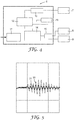
- Fig. 4 shows an exemplary block diagram of an electronic circuitry 6.
- the electronic circuitry 6 has a microcontroller 12 for controlling the functions of the dental light polymerization device 1.
- the microcontroller 12 is electrically connected to the signal generator 13 that is electrically connected to the transmitter 7.
- the signal general 13 provides the excitation signal for powering the transmitter 7.
- the microcontroller 12 is electrically connected to a signal evaluation unit 14 that is electrically to both, the first and second receiver 8, 9.
- a multiplexer 15 is arranged within the electrical connection between the signal evaluation unit 14 and the first and second receiver 8, 9.
- the multiplexer 15 is further electrically connected with the microcontroller.
- the signal evaluation unit 14 is configured to perform the determination of the difference between the excitation signal and the response signal received from the first and second receiver 8, 9.
- An indicator 16 (for example an indicator lamp) is electrically connected to the microcontroller, for example for indication a mode of operation and/or for acknowledging the recognition of a user input.
- the electronic circuit has a power unit 17 that is configured to power the electronic circuit 6 and which is connected to the battery (not shown) of the dental light polymerization device.
- Fig. 5 illustrates a diagram showing an excitation signal 20 relative to a response signal 21 measured between the transmitter and one of the first and second receiver in a situation in which a user touches the first or second touch surface, respectively. While in absence of a user's finger the response signal substantially corresponds to the excitation signal in the situation shown the response signal 21 significantly differs from the excitation signal 20.
- the maximum of the peak-to-peak value of the excitation signal 20 is about 2.72 Volts and the maximum of the peak-to-peak value of the response signal 21 is about 1.02 Volts. Accordingly the difference between the peak-to-peak value of the excitation and the response signal is about 1.7 Volts (response signal is about 38% of the excitation signal).
Landscapes
- Health & Medical Sciences (AREA)
- Oral & Maxillofacial Surgery (AREA)
- Dentistry (AREA)
- Epidemiology (AREA)
- Life Sciences & Earth Sciences (AREA)
- Animal Behavior & Ethology (AREA)
- General Health & Medical Sciences (AREA)
- Public Health (AREA)
- Veterinary Medicine (AREA)
- Dental Tools And Instruments Or Auxiliary Dental Instruments (AREA)
Claims (14)
- Dentale Lichtpolymerisationsvorrichtung (1), umfassend ein Gehäuse (2), eine Lichtquelle zum Emittieren von blauem Licht, einen piezoelektrischen Sender (7) und mindestens einen piezoelektrischen ersten Empfänger (8), wobei der Sender akustisch mit dem Gehäuse zum Senden einer akustischen Welle in dem Gehäuse und der erste Empfänger akustisch mit dem Gehäuse zum Aufnehmen der akustischen Welle aus dem Gehäuse gekoppelt ist, und wobei der Sender und der erste Empfänger voneinander beabstandet angeordnet sind, und wobei ein Abschnitt des Gehäuses zwischen dem Sender und dem ersten Empfänger eine erste berührungsempfindliche Oberfläche bildet.
- Dentale Lichtpolymerisationsvorrichtung nach Anspruch 1, wobei der Sender und der erste Empfänger innerhalb des Gehäuses angeordnet sind.
- Dentale Lichtpolymerisationsvorrichtung nach Anspruch 1 oder 2, wobei der Sender und der erste Empfänger jeweils ein piezoelektrisches Element umfassen, das mechanisch mit dem Gehäuse gekoppelt ist.
- Dentale Lichtpolymerisationsvorrichtung nach einem der vorstehenden Ansprüche, die ferner eine elektrische Steuerschaltung (6) umfasst, die mit dem Sender und dem ersten Empfänger verbunden oder verbindbar ist, wobei die Steuereinheit einen Signalgenerator umfasst und konfiguriert ist, um den Sender basierend auf einem Anregungssignal zu betreiben, das von dem Signalgenerator zum Erzeugen der akustischen Welle bereitgestellt wird, wobei die Steuereinheit ferner konfiguriert ist, um ein erstes Antwortsignal von dem ersten Empfänger basierend auf der akustischen Welle, die von dem ersten Empfänger aufgenommen wurde, zu empfangen.
- Dentale Lichtpolymerisationsvorrichtung nach Anspruch 4, wobei die Steuereinheit ferner konfiguriert ist, um eine Differenz zwischen dem Anregungssignal und dem ersten Antwortsignal zu bestimmen und basierend darauf ein erstes Steuersignal bereitzustellen, das für das Vorhandensein oder Fehlen eines Fingers eines Benutzers auf der ersten Berührungsoberfläche repräsentativ ist.
- Dentale Lichtpolymerisationsvorrichtung nach Anspruch 5, wobei die Differenz zwischen der Anregung und dem ersten Antwortsignal eine Differenz zwischen einer Anregungsamplitude des Anregungssignals und einer ersten Antwortamplitude des ersten Antwortsignals umfasst.
- Dentale Lichtpolymerisationsvorrichtung nach Anspruch 6, wobei eine erste Antwortamplitude, die niedrigere ist als die Anregungsamplitude, ein Vorhandensein eines Fingers eines Benutzers auf der ersten Berührungsoberfläche anzeigt.
- Dentale Lichtpolymerisationsvorrichtung nach einem der vorstehenden Ansprüche, umfassend mindestens einen piezoelektrischen zweiten Empfänger (9), wobei der zweite Empfänger akustisch mit dem Gehäuse gekoppelt ist, um die akustische Welle aus dem Gehäuse aufzunehmen, und wobei der Sender und der zweite Empfänger voneinander beabstandet angeordnet sind, und wobei ein weiterer Abschnitt des Gehäuses zwischen dem Sender und dem zweiten Empfänger eine zweite Berührungsoberfläche bildet.
- Dentale Lichtpolymerisationsvorrichtung nach einem der vorstehenden Ansprüche, wobei das Gehäuse einen Griffabschnitt der dentalen Lichtpolymerisationsvorrichtung bildet, und wobei die dentale Lichtpolymerisationsvorrichtung ferner einen Spitzenabschnitt aufweist, der von dem Griffabschnitt vorsteht, wobei der Spitzenabschnitt an einem freien Ende einen Lichtausgang bildet, aus dem durch die Lichtquelle erzeugtes Licht emittiert wird, wenn die Lichtquelle aktiviert wird.
- Dentale Lichtpolymerisationsvorrichtung nach einem der vorstehenden Ansprüche, ferner umfassend eine wiederaufladbare Batterie, die in dem Gehäuse eingekapselt ist.
- Dentale Lichtpolymerisationsvorrichtung nach einem der vorstehenden Ansprüche, die keinen beweglichen Aktuator, insbesondere keinen Schalter oder Knopf, zum Betreiben der dentalen Lichtpolymerisationsvorrichtung aufweist.
- Dentale Lichtpolymerisationsvorrichtung nach einem der vorstehenden Ansprüche, bei der eine Indikatorfunktion vorgesehen ist, die eine Erkennung eines Fingers eines Benutzers auf dem Gehäuse bestätigt.
- Dentale Lichtpolymerisationsvorrichtung nach Anspruch 12, wobei die Indikatorfunktion mindestens eines von einem hörbaren, optischen und taktilen Signal umfasst.
- Dentale Lichtpolymerisationsvorrichtung nach einem der vorstehenden Ansprüche, wobei mindestens ein Abschnitt des Gehäuses lichtdurchlässig ist, wobei die dentale Lichtpolymerisationsvorrichtung ferner eine Beleuchtungsvorrichtung aufweist, die in dem Gehäuse angeordnet ist.
Priority Applications (3)
| Application Number | Priority Date | Filing Date | Title |
|---|---|---|---|
| EP17160707.0A EP3375408B1 (de) | 2017-03-14 | 2017-03-14 | Zahnärztliche lichtpolymerisierungsvorrichtung |
| PCT/US2018/021993 WO2018169860A1 (en) | 2017-03-14 | 2018-03-12 | Dental light polymerization device |
| US16/493,873 US20210113315A1 (en) | 2017-03-14 | 2018-03-12 | Dental light polymerization device |
Applications Claiming Priority (1)
| Application Number | Priority Date | Filing Date | Title |
|---|---|---|---|
| EP17160707.0A EP3375408B1 (de) | 2017-03-14 | 2017-03-14 | Zahnärztliche lichtpolymerisierungsvorrichtung |
Publications (2)
| Publication Number | Publication Date |
|---|---|
| EP3375408A1 EP3375408A1 (de) | 2018-09-19 |
| EP3375408B1 true EP3375408B1 (de) | 2019-05-15 |
Family
ID=58347100
Family Applications (1)
| Application Number | Title | Priority Date | Filing Date |
|---|---|---|---|
| EP17160707.0A Active EP3375408B1 (de) | 2017-03-14 | 2017-03-14 | Zahnärztliche lichtpolymerisierungsvorrichtung |
Country Status (3)
| Country | Link |
|---|---|
| US (1) | US20210113315A1 (de) |
| EP (1) | EP3375408B1 (de) |
| WO (1) | WO2018169860A1 (de) |
Family Cites Families (3)
| Publication number | Priority date | Publication date | Assignee | Title |
|---|---|---|---|---|
| US6089740A (en) * | 1997-08-28 | 2000-07-18 | Kreativ, Inc. | Multipurpose dental lamp apparatus |
| JP2004163262A (ja) * | 2002-11-13 | 2004-06-10 | Touch Panel Systems Kk | 音響波型接触検出装置 |
| EP2373249B1 (de) * | 2008-12-30 | 2018-04-11 | Ultradent Products, Inc. | Zahnmedizinisches härtungslicht mit einteiligem design als kühlkörper |
-
2017
- 2017-03-14 EP EP17160707.0A patent/EP3375408B1/de active Active
-
2018
- 2018-03-12 WO PCT/US2018/021993 patent/WO2018169860A1/en not_active Ceased
- 2018-03-12 US US16/493,873 patent/US20210113315A1/en not_active Abandoned
Non-Patent Citations (1)
| Title |
|---|
| None * |
Also Published As
| Publication number | Publication date |
|---|---|
| US20210113315A1 (en) | 2021-04-22 |
| WO2018169860A1 (en) | 2018-09-20 |
| EP3375408A1 (de) | 2018-09-19 |
Similar Documents
| Publication | Publication Date | Title |
|---|---|---|
| EP2964141B1 (de) | Zahnärztliche vorrichtung für die zahnbehandlung in einem mund | |
| US8898843B2 (en) | Electric toothbrush capable of receiving user operations | |
| ES2989733T3 (es) | Determinación de las características estructurales de un objeto | |
| ES3035093T3 (en) | System and method for determining structural characteristics of an object | |
| KR101615438B1 (ko) | 전동칫솔 동작 상태 감지 장치 | |
| AU2020357834A1 (en) | Wireless teeth whitening system | |
| WO2004079714A1 (ja) | 撥弦タイプの電子楽器 | |
| EP3375408B1 (de) | Zahnärztliche lichtpolymerisierungsvorrichtung | |
| US20060252005A1 (en) | Apparatus for providing radiation at multiple wavelengths and method of operating same | |
| CN109982632B (zh) | 便携式测量仪器 | |
| CN102104374B (zh) | 按键装置及其系统 | |
| JP4697444B2 (ja) | 通信装置 | |
| CN216090888U (zh) | 一种压力感应检测的电机 | |
| EP4649979A2 (de) | Aerosolerzeugungsvorrichtung mit flexibler abdeckung | |
| KR101821563B1 (ko) | 자동 동작 치과 진료 장치 | |
| JP6046841B2 (ja) | スイッチ、及びこのスイッチを備える鍵盤楽器 | |
| JP2004093456A (ja) | 放射線検出器 | |
| JP6070639B2 (ja) | 光学式タッチスイッチ及びフィールド機器 | |
| JP2013201060A (ja) | スイッチ、及びこのスイッチを備える鍵盤楽器 | |
| CN121622299A (zh) | 基于红外式感应的压力监测电动牙刷 | |
| TWM444153U (zh) | 牙科用手機調光器 | |
| US20230094611A1 (en) | Medical or dental hand-held treatment instrument with a capacitive sensor | |
| JP3206472U (ja) | 紫外線硬化材料硬化装置 | |
| KR20260003287A (ko) | 에어로졸 발생 장치 | |
| RU94019814A (ru) | Устройство для светорефлексотерапии |
Legal Events
| Date | Code | Title | Description |
|---|---|---|---|
| PUAI | Public reference made under article 153(3) epc to a published international application that has entered the european phase |
Free format text: ORIGINAL CODE: 0009012 |
|
| STAA | Information on the status of an ep patent application or granted ep patent |
Free format text: STATUS: REQUEST FOR EXAMINATION WAS MADE |
|
| 17P | Request for examination filed |
Effective date: 20180214 |
|
| AK | Designated contracting states |
Kind code of ref document: A1 Designated state(s): AL AT BE BG CH CY CZ DE DK EE ES FI FR GB GR HR HU IE IS IT LI LT LU LV MC MK MT NL NO PL PT RO RS SE SI SK SM TR |
|
| AX | Request for extension of the european patent |
Extension state: BA ME |
|
| GRAP | Despatch of communication of intention to grant a patent |
Free format text: ORIGINAL CODE: EPIDOSNIGR1 |
|
| STAA | Information on the status of an ep patent application or granted ep patent |
Free format text: STATUS: GRANT OF PATENT IS INTENDED |
|
| INTG | Intention to grant announced |
Effective date: 20181217 |
|
| GRAS | Grant fee paid |
Free format text: ORIGINAL CODE: EPIDOSNIGR3 |
|
| GRAA | (expected) grant |
Free format text: ORIGINAL CODE: 0009210 |
|
| STAA | Information on the status of an ep patent application or granted ep patent |
Free format text: STATUS: THE PATENT HAS BEEN GRANTED |
|
| AK | Designated contracting states |
Kind code of ref document: B1 Designated state(s): AL AT BE BG CH CY CZ DE DK EE ES FI FR GB GR HR HU IE IS IT LI LT LU LV MC MK MT NL NO PL PT RO RS SE SI SK SM TR |
|
| REG | Reference to a national code |
Ref country code: CH Ref legal event code: EP |
|
| REG | Reference to a national code |
Ref country code: DE Ref legal event code: R096 Ref document number: 602017003816 Country of ref document: DE |
|
| REG | Reference to a national code |
Ref country code: IE Ref legal event code: FG4D |
|
| REG | Reference to a national code |
Ref country code: NL Ref legal event code: MP Effective date: 20190515 |
|
| REG | Reference to a national code |
Ref country code: LT Ref legal event code: MG4D |
|
| PG25 | Lapsed in a contracting state [announced via postgrant information from national office to epo] |
Ref country code: NL Free format text: LAPSE BECAUSE OF FAILURE TO SUBMIT A TRANSLATION OF THE DESCRIPTION OR TO PAY THE FEE WITHIN THE PRESCRIBED TIME-LIMIT Effective date: 20190515 Ref country code: AL Free format text: LAPSE BECAUSE OF FAILURE TO SUBMIT A TRANSLATION OF THE DESCRIPTION OR TO PAY THE FEE WITHIN THE PRESCRIBED TIME-LIMIT Effective date: 20190515 Ref country code: SE Free format text: LAPSE BECAUSE OF FAILURE TO SUBMIT A TRANSLATION OF THE DESCRIPTION OR TO PAY THE FEE WITHIN THE PRESCRIBED TIME-LIMIT Effective date: 20190515 Ref country code: PT Free format text: LAPSE BECAUSE OF FAILURE TO SUBMIT A TRANSLATION OF THE DESCRIPTION OR TO PAY THE FEE WITHIN THE PRESCRIBED TIME-LIMIT Effective date: 20190915 Ref country code: FI Free format text: LAPSE BECAUSE OF FAILURE TO SUBMIT A TRANSLATION OF THE DESCRIPTION OR TO PAY THE FEE WITHIN THE PRESCRIBED TIME-LIMIT Effective date: 20190515 Ref country code: NO Free format text: LAPSE BECAUSE OF FAILURE TO SUBMIT A TRANSLATION OF THE DESCRIPTION OR TO PAY THE FEE WITHIN THE PRESCRIBED TIME-LIMIT Effective date: 20190815 Ref country code: LT Free format text: LAPSE BECAUSE OF FAILURE TO SUBMIT A TRANSLATION OF THE DESCRIPTION OR TO PAY THE FEE WITHIN THE PRESCRIBED TIME-LIMIT Effective date: 20190515 Ref country code: HR Free format text: LAPSE BECAUSE OF FAILURE TO SUBMIT A TRANSLATION OF THE DESCRIPTION OR TO PAY THE FEE WITHIN THE PRESCRIBED TIME-LIMIT Effective date: 20190515 Ref country code: ES Free format text: LAPSE BECAUSE OF FAILURE TO SUBMIT A TRANSLATION OF THE DESCRIPTION OR TO PAY THE FEE WITHIN THE PRESCRIBED TIME-LIMIT Effective date: 20190515 |
|
| PG25 | Lapsed in a contracting state [announced via postgrant information from national office to epo] |
Ref country code: RS Free format text: LAPSE BECAUSE OF FAILURE TO SUBMIT A TRANSLATION OF THE DESCRIPTION OR TO PAY THE FEE WITHIN THE PRESCRIBED TIME-LIMIT Effective date: 20190515 Ref country code: BG Free format text: LAPSE BECAUSE OF FAILURE TO SUBMIT A TRANSLATION OF THE DESCRIPTION OR TO PAY THE FEE WITHIN THE PRESCRIBED TIME-LIMIT Effective date: 20190815 Ref country code: LV Free format text: LAPSE BECAUSE OF FAILURE TO SUBMIT A TRANSLATION OF THE DESCRIPTION OR TO PAY THE FEE WITHIN THE PRESCRIBED TIME-LIMIT Effective date: 20190515 Ref country code: GR Free format text: LAPSE BECAUSE OF FAILURE TO SUBMIT A TRANSLATION OF THE DESCRIPTION OR TO PAY THE FEE WITHIN THE PRESCRIBED TIME-LIMIT Effective date: 20190816 |
|
| REG | Reference to a national code |
Ref country code: AT Ref legal event code: MK05 Ref document number: 1132532 Country of ref document: AT Kind code of ref document: T Effective date: 20190515 |
|
| PG25 | Lapsed in a contracting state [announced via postgrant information from national office to epo] |
Ref country code: AT Free format text: LAPSE BECAUSE OF FAILURE TO SUBMIT A TRANSLATION OF THE DESCRIPTION OR TO PAY THE FEE WITHIN THE PRESCRIBED TIME-LIMIT Effective date: 20190515 Ref country code: DK Free format text: LAPSE BECAUSE OF FAILURE TO SUBMIT A TRANSLATION OF THE DESCRIPTION OR TO PAY THE FEE WITHIN THE PRESCRIBED TIME-LIMIT Effective date: 20190515 Ref country code: EE Free format text: LAPSE BECAUSE OF FAILURE TO SUBMIT A TRANSLATION OF THE DESCRIPTION OR TO PAY THE FEE WITHIN THE PRESCRIBED TIME-LIMIT Effective date: 20190515 Ref country code: SK Free format text: LAPSE BECAUSE OF FAILURE TO SUBMIT A TRANSLATION OF THE DESCRIPTION OR TO PAY THE FEE WITHIN THE PRESCRIBED TIME-LIMIT Effective date: 20190515 Ref country code: CZ Free format text: LAPSE BECAUSE OF FAILURE TO SUBMIT A TRANSLATION OF THE DESCRIPTION OR TO PAY THE FEE WITHIN THE PRESCRIBED TIME-LIMIT Effective date: 20190515 |
|
| REG | Reference to a national code |
Ref country code: DE Ref legal event code: R097 Ref document number: 602017003816 Country of ref document: DE |
|
| PG25 | Lapsed in a contracting state [announced via postgrant information from national office to epo] |
Ref country code: SM Free format text: LAPSE BECAUSE OF FAILURE TO SUBMIT A TRANSLATION OF THE DESCRIPTION OR TO PAY THE FEE WITHIN THE PRESCRIBED TIME-LIMIT Effective date: 20190515 Ref country code: IT Free format text: LAPSE BECAUSE OF FAILURE TO SUBMIT A TRANSLATION OF THE DESCRIPTION OR TO PAY THE FEE WITHIN THE PRESCRIBED TIME-LIMIT Effective date: 20190515 |
|
| PLBE | No opposition filed within time limit |
Free format text: ORIGINAL CODE: 0009261 |
|
| STAA | Information on the status of an ep patent application or granted ep patent |
Free format text: STATUS: NO OPPOSITION FILED WITHIN TIME LIMIT |
|
| PG25 | Lapsed in a contracting state [announced via postgrant information from national office to epo] |
Ref country code: TR Free format text: LAPSE BECAUSE OF FAILURE TO SUBMIT A TRANSLATION OF THE DESCRIPTION OR TO PAY THE FEE WITHIN THE PRESCRIBED TIME-LIMIT Effective date: 20190515 |
|
| 26N | No opposition filed |
Effective date: 20200218 |
|
| PG25 | Lapsed in a contracting state [announced via postgrant information from national office to epo] |
Ref country code: PL Free format text: LAPSE BECAUSE OF FAILURE TO SUBMIT A TRANSLATION OF THE DESCRIPTION OR TO PAY THE FEE WITHIN THE PRESCRIBED TIME-LIMIT Effective date: 20190515 |
|
| PG25 | Lapsed in a contracting state [announced via postgrant information from national office to epo] |
Ref country code: MC Free format text: LAPSE BECAUSE OF FAILURE TO SUBMIT A TRANSLATION OF THE DESCRIPTION OR TO PAY THE FEE WITHIN THE PRESCRIBED TIME-LIMIT Effective date: 20190515 |
|
| REG | Reference to a national code |
Ref country code: CH Ref legal event code: PL |
|
| REG | Reference to a national code |
Ref country code: BE Ref legal event code: MM Effective date: 20200331 |
|
| PG25 | Lapsed in a contracting state [announced via postgrant information from national office to epo] |
Ref country code: LU Free format text: LAPSE BECAUSE OF NON-PAYMENT OF DUE FEES Effective date: 20200314 |
|
| PG25 | Lapsed in a contracting state [announced via postgrant information from national office to epo] |
Ref country code: IE Free format text: LAPSE BECAUSE OF NON-PAYMENT OF DUE FEES Effective date: 20200314 Ref country code: LI Free format text: LAPSE BECAUSE OF NON-PAYMENT OF DUE FEES Effective date: 20200331 Ref country code: FR Free format text: LAPSE BECAUSE OF NON-PAYMENT OF DUE FEES Effective date: 20200331 Ref country code: CH Free format text: LAPSE BECAUSE OF NON-PAYMENT OF DUE FEES Effective date: 20200331 |
|
| PG25 | Lapsed in a contracting state [announced via postgrant information from national office to epo] |
Ref country code: BE Free format text: LAPSE BECAUSE OF NON-PAYMENT OF DUE FEES Effective date: 20200331 |
|
| GBPC | Gb: european patent ceased through non-payment of renewal fee |
Effective date: 20210314 |
|
| PG25 | Lapsed in a contracting state [announced via postgrant information from national office to epo] |
Ref country code: GB Free format text: LAPSE BECAUSE OF NON-PAYMENT OF DUE FEES Effective date: 20210314 |
|
| PG25 | Lapsed in a contracting state [announced via postgrant information from national office to epo] |
Ref country code: MT Free format text: LAPSE BECAUSE OF FAILURE TO SUBMIT A TRANSLATION OF THE DESCRIPTION OR TO PAY THE FEE WITHIN THE PRESCRIBED TIME-LIMIT Effective date: 20190515 Ref country code: CY Free format text: LAPSE BECAUSE OF FAILURE TO SUBMIT A TRANSLATION OF THE DESCRIPTION OR TO PAY THE FEE WITHIN THE PRESCRIBED TIME-LIMIT Effective date: 20190515 |
|
| PG25 | Lapsed in a contracting state [announced via postgrant information from national office to epo] |
Ref country code: RO Free format text: LAPSE BECAUSE OF FAILURE TO SUBMIT A TRANSLATION OF THE DESCRIPTION OR TO PAY THE FEE WITHIN THE PRESCRIBED TIME-LIMIT Effective date: 20190515 Ref country code: MK Free format text: LAPSE BECAUSE OF FAILURE TO SUBMIT A TRANSLATION OF THE DESCRIPTION OR TO PAY THE FEE WITHIN THE PRESCRIBED TIME-LIMIT Effective date: 20190515 Ref country code: IS Free format text: LAPSE BECAUSE OF FAILURE TO SUBMIT A TRANSLATION OF THE DESCRIPTION OR TO PAY THE FEE WITHIN THE PRESCRIBED TIME-LIMIT Effective date: 20190915 |
|
| PG25 | Lapsed in a contracting state [announced via postgrant information from national office to epo] |
Ref country code: SI Free format text: LAPSE BECAUSE OF FAILURE TO SUBMIT A TRANSLATION OF THE DESCRIPTION OR TO PAY THE FEE WITHIN THE PRESCRIBED TIME-LIMIT Effective date: 20190515 |
|
| REG | Reference to a national code |
Ref country code: DE Ref legal event code: R081 Ref document number: 602017003816 Country of ref document: DE Owner name: SOLVENTUM INTELLECTUAL PROPERTIES CO. (N.D.GES, US Free format text: FORMER OWNER: 3M INNOVATIVE PROPERTIES COMPANY, SAINT PAUL, MINN., US |
|
| PGFP | Annual fee paid to national office [announced via postgrant information from national office to epo] |
Ref country code: DE Payment date: 20250218 Year of fee payment: 9 |