EP3375658A2 - Ladestationssystem für elektrofahrzeuge - Google Patents
Ladestationssystem für elektrofahrzeuge Download PDFInfo
- Publication number
- EP3375658A2 EP3375658A2 EP18020024.8A EP18020024A EP3375658A2 EP 3375658 A2 EP3375658 A2 EP 3375658A2 EP 18020024 A EP18020024 A EP 18020024A EP 3375658 A2 EP3375658 A2 EP 3375658A2
- Authority
- EP
- European Patent Office
- Prior art keywords
- charging station
- housing
- station system
- main component
- standardized
- Prior art date
- Legal status (The legal status is an assumption and is not a legal conclusion. Google has not performed a legal analysis and makes no representation as to the accuracy of the status listed.)
- Pending
Links
Images



Classifications
-
- H—ELECTRICITY
- H02—GENERATION; CONVERSION OR DISTRIBUTION OF ELECTRIC POWER
- H02J—ELECTRIC POWER NETWORKS; CIRCUIT ARRANGEMENTS OR SYSTEMS FOR SUPPLYING OR DISTRIBUTING ELECTRIC POWER; SYSTEMS FOR STORING ELECTRIC ENERGY
- H02J7/00—Circuit arrangements for charging or discharging batteries or for supplying loads from batteries
- H02J7/70—Circuit arrangements for charging or discharging batteries or for supplying loads from batteries characterised by the mechanical construction
-
- B—PERFORMING OPERATIONS; TRANSPORTING
- B60—VEHICLES IN GENERAL
- B60L—PROPULSION OF ELECTRICALLY-PROPELLED VEHICLES; SUPPLYING ELECTRIC POWER FOR AUXILIARY EQUIPMENT OF ELECTRICALLY-PROPELLED VEHICLES; ELECTRODYNAMIC BRAKE SYSTEMS FOR VEHICLES IN GENERAL; MAGNETIC SUSPENSION OR LEVITATION FOR VEHICLES; MONITORING OPERATING VARIABLES OF ELECTRICALLY-PROPELLED VEHICLES; ELECTRIC SAFETY DEVICES FOR ELECTRICALLY-PROPELLED VEHICLES
- B60L53/00—Methods of charging batteries, specially adapted for electric vehicles; Charging stations or on-board charging equipment therefor; Exchange of energy storage elements in electric vehicles
- B60L53/10—Methods of charging batteries, specially adapted for electric vehicles; Charging stations or on-board charging equipment therefor; Exchange of energy storage elements in electric vehicles characterised by the energy transfer between the charging station and the vehicle
- B60L53/14—Conductive energy transfer
-
- B—PERFORMING OPERATIONS; TRANSPORTING
- B60—VEHICLES IN GENERAL
- B60S—SERVICING, CLEANING, REPAIRING, SUPPORTING, LIFTING, OR MANOEUVRING OF VEHICLES, NOT OTHERWISE PROVIDED FOR
- B60S5/00—Servicing, maintaining, repairing, or refitting of vehicles
-
- B—PERFORMING OPERATIONS; TRANSPORTING
- B60—VEHICLES IN GENERAL
- B60L—PROPULSION OF ELECTRICALLY-PROPELLED VEHICLES; SUPPLYING ELECTRIC POWER FOR AUXILIARY EQUIPMENT OF ELECTRICALLY-PROPELLED VEHICLES; ELECTRODYNAMIC BRAKE SYSTEMS FOR VEHICLES IN GENERAL; MAGNETIC SUSPENSION OR LEVITATION FOR VEHICLES; MONITORING OPERATING VARIABLES OF ELECTRICALLY-PROPELLED VEHICLES; ELECTRIC SAFETY DEVICES FOR ELECTRICALLY-PROPELLED VEHICLES
- B60L53/00—Methods of charging batteries, specially adapted for electric vehicles; Charging stations or on-board charging equipment therefor; Exchange of energy storage elements in electric vehicles
-
- B—PERFORMING OPERATIONS; TRANSPORTING
- B60—VEHICLES IN GENERAL
- B60L—PROPULSION OF ELECTRICALLY-PROPELLED VEHICLES; SUPPLYING ELECTRIC POWER FOR AUXILIARY EQUIPMENT OF ELECTRICALLY-PROPELLED VEHICLES; ELECTRODYNAMIC BRAKE SYSTEMS FOR VEHICLES IN GENERAL; MAGNETIC SUSPENSION OR LEVITATION FOR VEHICLES; MONITORING OPERATING VARIABLES OF ELECTRICALLY-PROPELLED VEHICLES; ELECTRIC SAFETY DEVICES FOR ELECTRICALLY-PROPELLED VEHICLES
- B60L53/00—Methods of charging batteries, specially adapted for electric vehicles; Charging stations or on-board charging equipment therefor; Exchange of energy storage elements in electric vehicles
- B60L53/20—Methods of charging batteries, specially adapted for electric vehicles; Charging stations or on-board charging equipment therefor; Exchange of energy storage elements in electric vehicles characterised by converters located in the vehicle
- B60L53/22—Constructional details or arrangements of charging converters specially adapted for charging electric vehicles
-
- B—PERFORMING OPERATIONS; TRANSPORTING
- B60—VEHICLES IN GENERAL
- B60L—PROPULSION OF ELECTRICALLY-PROPELLED VEHICLES; SUPPLYING ELECTRIC POWER FOR AUXILIARY EQUIPMENT OF ELECTRICALLY-PROPELLED VEHICLES; ELECTRODYNAMIC BRAKE SYSTEMS FOR VEHICLES IN GENERAL; MAGNETIC SUSPENSION OR LEVITATION FOR VEHICLES; MONITORING OPERATING VARIABLES OF ELECTRICALLY-PROPELLED VEHICLES; ELECTRIC SAFETY DEVICES FOR ELECTRICALLY-PROPELLED VEHICLES
- B60L53/00—Methods of charging batteries, specially adapted for electric vehicles; Charging stations or on-board charging equipment therefor; Exchange of energy storage elements in electric vehicles
- B60L53/30—Constructional details of charging stations
-
- B—PERFORMING OPERATIONS; TRANSPORTING
- B60—VEHICLES IN GENERAL
- B60L—PROPULSION OF ELECTRICALLY-PROPELLED VEHICLES; SUPPLYING ELECTRIC POWER FOR AUXILIARY EQUIPMENT OF ELECTRICALLY-PROPELLED VEHICLES; ELECTRODYNAMIC BRAKE SYSTEMS FOR VEHICLES IN GENERAL; MAGNETIC SUSPENSION OR LEVITATION FOR VEHICLES; MONITORING OPERATING VARIABLES OF ELECTRICALLY-PROPELLED VEHICLES; ELECTRIC SAFETY DEVICES FOR ELECTRICALLY-PROPELLED VEHICLES
- B60L53/00—Methods of charging batteries, specially adapted for electric vehicles; Charging stations or on-board charging equipment therefor; Exchange of energy storage elements in electric vehicles
- B60L53/30—Constructional details of charging stations
- B60L53/302—Cooling of charging equipment
-
- B—PERFORMING OPERATIONS; TRANSPORTING
- B60—VEHICLES IN GENERAL
- B60L—PROPULSION OF ELECTRICALLY-PROPELLED VEHICLES; SUPPLYING ELECTRIC POWER FOR AUXILIARY EQUIPMENT OF ELECTRICALLY-PROPELLED VEHICLES; ELECTRODYNAMIC BRAKE SYSTEMS FOR VEHICLES IN GENERAL; MAGNETIC SUSPENSION OR LEVITATION FOR VEHICLES; MONITORING OPERATING VARIABLES OF ELECTRICALLY-PROPELLED VEHICLES; ELECTRIC SAFETY DEVICES FOR ELECTRICALLY-PROPELLED VEHICLES
- B60L53/00—Methods of charging batteries, specially adapted for electric vehicles; Charging stations or on-board charging equipment therefor; Exchange of energy storage elements in electric vehicles
- B60L53/30—Constructional details of charging stations
- B60L53/31—Charging columns specially adapted for electric vehicles
-
- B—PERFORMING OPERATIONS; TRANSPORTING
- B60—VEHICLES IN GENERAL
- B60L—PROPULSION OF ELECTRICALLY-PROPELLED VEHICLES; SUPPLYING ELECTRIC POWER FOR AUXILIARY EQUIPMENT OF ELECTRICALLY-PROPELLED VEHICLES; ELECTRODYNAMIC BRAKE SYSTEMS FOR VEHICLES IN GENERAL; MAGNETIC SUSPENSION OR LEVITATION FOR VEHICLES; MONITORING OPERATING VARIABLES OF ELECTRICALLY-PROPELLED VEHICLES; ELECTRIC SAFETY DEVICES FOR ELECTRICALLY-PROPELLED VEHICLES
- B60L53/00—Methods of charging batteries, specially adapted for electric vehicles; Charging stations or on-board charging equipment therefor; Exchange of energy storage elements in electric vehicles
- B60L53/60—Monitoring or controlling charging stations
- B60L53/66—Data transfer between charging stations and vehicles
-
- H—ELECTRICITY
- H02—GENERATION; CONVERSION OR DISTRIBUTION OF ELECTRIC POWER
- H02J—ELECTRIC POWER NETWORKS; CIRCUIT ARRANGEMENTS OR SYSTEMS FOR SUPPLYING OR DISTRIBUTING ELECTRIC POWER; SYSTEMS FOR STORING ELECTRIC ENERGY
- H02J7/00—Circuit arrangements for charging or discharging batteries or for supplying loads from batteries
- H02J7/70—Circuit arrangements for charging or discharging batteries or for supplying loads from batteries characterised by the mechanical construction
- H02J7/751—Circuit arrangements for charging or discharging batteries or for supplying loads from batteries characterised by the mechanical construction concerning the insertion or the connection of the batteries
-
- H—ELECTRICITY
- H05—ELECTRIC TECHNIQUES NOT OTHERWISE PROVIDED FOR
- H05K—PRINTED CIRCUITS; CASINGS OR CONSTRUCTIONAL DETAILS OF ELECTRIC APPARATUS; MANUFACTURE OF ASSEMBLAGES OF ELECTRICAL COMPONENTS
- H05K7/00—Constructional details common to different types of electric apparatus
- H05K7/20—Modifications to facilitate cooling, ventilating, or heating
- H05K7/2089—Modifications to facilitate cooling, ventilating, or heating for power electronics, e.g. for inverters for controlling motor
- H05K7/20927—Liquid coolant without phase change
-
- B—PERFORMING OPERATIONS; TRANSPORTING
- B60—VEHICLES IN GENERAL
- B60L—PROPULSION OF ELECTRICALLY-PROPELLED VEHICLES; SUPPLYING ELECTRIC POWER FOR AUXILIARY EQUIPMENT OF ELECTRICALLY-PROPELLED VEHICLES; ELECTRODYNAMIC BRAKE SYSTEMS FOR VEHICLES IN GENERAL; MAGNETIC SUSPENSION OR LEVITATION FOR VEHICLES; MONITORING OPERATING VARIABLES OF ELECTRICALLY-PROPELLED VEHICLES; ELECTRIC SAFETY DEVICES FOR ELECTRICALLY-PROPELLED VEHICLES
- B60L2210/00—Converter types
- B60L2210/10—DC to DC converters
-
- B—PERFORMING OPERATIONS; TRANSPORTING
- B60—VEHICLES IN GENERAL
- B60L—PROPULSION OF ELECTRICALLY-PROPELLED VEHICLES; SUPPLYING ELECTRIC POWER FOR AUXILIARY EQUIPMENT OF ELECTRICALLY-PROPELLED VEHICLES; ELECTRODYNAMIC BRAKE SYSTEMS FOR VEHICLES IN GENERAL; MAGNETIC SUSPENSION OR LEVITATION FOR VEHICLES; MONITORING OPERATING VARIABLES OF ELECTRICALLY-PROPELLED VEHICLES; ELECTRIC SAFETY DEVICES FOR ELECTRICALLY-PROPELLED VEHICLES
- B60L2210/00—Converter types
- B60L2210/30—AC to DC converters
-
- H—ELECTRICITY
- H02—GENERATION; CONVERSION OR DISTRIBUTION OF ELECTRIC POWER
- H02J—ELECTRIC POWER NETWORKS; CIRCUIT ARRANGEMENTS OR SYSTEMS FOR SUPPLYING OR DISTRIBUTING ELECTRIC POWER; SYSTEMS FOR STORING ELECTRIC ENERGY
- H02J2105/00—Networks for supplying or distributing electric power characterised by their spatial reach or by the load
- H02J2105/30—Networks for supplying or distributing electric power characterised by their spatial reach or by the load the load networks being external to vehicles, i.e. exchanging power with vehicles
- H02J2105/33—Networks for supplying or distributing electric power characterised by their spatial reach or by the load the load networks being external to vehicles, i.e. exchanging power with vehicles exchanging power with road vehicles
- H02J2105/37—Networks for supplying or distributing electric power characterised by their spatial reach or by the load the load networks being external to vehicles, i.e. exchanging power with vehicles exchanging power with road vehicles exchanging power with electric vehicles [EV] or with hybrid electric vehicles [HEV]
-
- Y—GENERAL TAGGING OF NEW TECHNOLOGICAL DEVELOPMENTS; GENERAL TAGGING OF CROSS-SECTIONAL TECHNOLOGIES SPANNING OVER SEVERAL SECTIONS OF THE IPC; TECHNICAL SUBJECTS COVERED BY FORMER USPC CROSS-REFERENCE ART COLLECTIONS [XRACs] AND DIGESTS
- Y02—TECHNOLOGIES OR APPLICATIONS FOR MITIGATION OR ADAPTATION AGAINST CLIMATE CHANGE
- Y02T—CLIMATE CHANGE MITIGATION TECHNOLOGIES RELATED TO TRANSPORTATION
- Y02T10/00—Road transport of goods or passengers
- Y02T10/60—Other road transportation technologies with climate change mitigation effect
- Y02T10/70—Energy storage systems for electromobility, e.g. batteries
-
- Y—GENERAL TAGGING OF NEW TECHNOLOGICAL DEVELOPMENTS; GENERAL TAGGING OF CROSS-SECTIONAL TECHNOLOGIES SPANNING OVER SEVERAL SECTIONS OF THE IPC; TECHNICAL SUBJECTS COVERED BY FORMER USPC CROSS-REFERENCE ART COLLECTIONS [XRACs] AND DIGESTS
- Y02—TECHNOLOGIES OR APPLICATIONS FOR MITIGATION OR ADAPTATION AGAINST CLIMATE CHANGE
- Y02T—CLIMATE CHANGE MITIGATION TECHNOLOGIES RELATED TO TRANSPORTATION
- Y02T10/00—Road transport of goods or passengers
- Y02T10/60—Other road transportation technologies with climate change mitigation effect
- Y02T10/7072—Electromobility specific charging systems or methods for batteries, ultracapacitors, supercapacitors or double-layer capacitors
-
- Y—GENERAL TAGGING OF NEW TECHNOLOGICAL DEVELOPMENTS; GENERAL TAGGING OF CROSS-SECTIONAL TECHNOLOGIES SPANNING OVER SEVERAL SECTIONS OF THE IPC; TECHNICAL SUBJECTS COVERED BY FORMER USPC CROSS-REFERENCE ART COLLECTIONS [XRACs] AND DIGESTS
- Y02—TECHNOLOGIES OR APPLICATIONS FOR MITIGATION OR ADAPTATION AGAINST CLIMATE CHANGE
- Y02T—CLIMATE CHANGE MITIGATION TECHNOLOGIES RELATED TO TRANSPORTATION
- Y02T90/00—Enabling technologies or technologies with a potential or indirect contribution to GHG emissions mitigation
- Y02T90/10—Technologies relating to charging of electric vehicles
- Y02T90/12—Electric charging stations
-
- Y—GENERAL TAGGING OF NEW TECHNOLOGICAL DEVELOPMENTS; GENERAL TAGGING OF CROSS-SECTIONAL TECHNOLOGIES SPANNING OVER SEVERAL SECTIONS OF THE IPC; TECHNICAL SUBJECTS COVERED BY FORMER USPC CROSS-REFERENCE ART COLLECTIONS [XRACs] AND DIGESTS
- Y02—TECHNOLOGIES OR APPLICATIONS FOR MITIGATION OR ADAPTATION AGAINST CLIMATE CHANGE
- Y02T—CLIMATE CHANGE MITIGATION TECHNOLOGIES RELATED TO TRANSPORTATION
- Y02T90/00—Enabling technologies or technologies with a potential or indirect contribution to GHG emissions mitigation
- Y02T90/10—Technologies relating to charging of electric vehicles
- Y02T90/14—Plug-in electric vehicles
-
- Y—GENERAL TAGGING OF NEW TECHNOLOGICAL DEVELOPMENTS; GENERAL TAGGING OF CROSS-SECTIONAL TECHNOLOGIES SPANNING OVER SEVERAL SECTIONS OF THE IPC; TECHNICAL SUBJECTS COVERED BY FORMER USPC CROSS-REFERENCE ART COLLECTIONS [XRACs] AND DIGESTS
- Y02—TECHNOLOGIES OR APPLICATIONS FOR MITIGATION OR ADAPTATION AGAINST CLIMATE CHANGE
- Y02T—CLIMATE CHANGE MITIGATION TECHNOLOGIES RELATED TO TRANSPORTATION
- Y02T90/00—Enabling technologies or technologies with a potential or indirect contribution to GHG emissions mitigation
- Y02T90/10—Technologies relating to charging of electric vehicles
- Y02T90/16—Information or communication technologies improving the operation of electric vehicles
Definitions
- the present invention relates to a charging station system, in particular for electric vehicles.
- Charging station systems for supplying electrical vehicles with electrical energy are known from the prior art. Charging stations are equipped with one or more charging units. These loading units are usually designed as a complete, prefabricated unit. In one unit are devices for power supply, cooling, controls and charging cable in a fixed arrangement, number and configuration. The loading units are designed for a fixed application and / or a specific location. New use cases and / or locations with changed conditions compared to previous locations require the planning and construction of new loading units. It is not possible with previously known charging station systems to consider flexibly the local and current conditions and requirements when building a charging station.
- a charging station system in particular for electric vehicles, wherein the charging station system has at least one housing, wherein the charging station system has a plurality of main components, characterized in that the housing and the main components are standardized so that the main components in the housing arrange modular to let.
- the electrical power and the cooling capacity of the charging station can be selected independently.
- the electrical power of the charging station can be changed, for example, without the cooling power is changed.
- the cooling capacity of the charging station can be changed without the electrical performance of the charging station is changed. It is hereby advantageously provided a charging station system that enables a scaling of the electrical power of a charging station regardless of the cooling capacity of the charging station. It is hereby advantageously made available a charging station system that allows a scaling of the cooling capacity of a charging station regardless of the electrical power of the charging station.
- the main components and the housing have in their dimensions a coordinated standardization, wherein in particular the housing has internal dimensions, which are determined by the outer dimensions of the main components.
- the housing has internal dimensions which enable an arrangement of several main components in the housing while optimally utilizing the volume of the housing.
- the housing has internal dimensions which are composed of an integer multiple of the outer dimensions of a main component and a distance to be maintained between the housing and the main component.
- the housing has a square base.
- the outer dimensions of the base surface of the housing are selected so that the housing can be placed with the base side on one or more europallets without overhanging.
- Euro pallet in the sense of this invention refers to a reusable transport pallet standardized according to EN 13698-1.
- the base of the housing has outer edges of a maximum length of 1200 mm. In an alternative preferred embodiment, the base of the housing Outside edges of a maximum length of an integer multiple of 1200 mm.
- the charging station system comprises a plurality of main components, each of these main components having a control cabinet, the main component having at least one module, the architecture of the module being characterized in that the module is modular in the control cabinet can arrange.
- the cabinet is designed as a 19-inch rack.
- a 19-inch rack refers to an EIA 310-D, IEC 60297, and DIN 41494 SC48D standardized rack for electronic devices, with the rack being a standard 19-inch wide, i. 482.6 mm, the rack further having holding devices for the electronic devices mounted vertically at a standard distance from a height unit, one height unit being 1.75 inches, i. 44.45 mm, corresponds.
- the exterior dimensions of the modules are selected to be arranged in a 19 inch rack.
- main component which can be modular. It is hereby advantageously possible to build main components with different properties quickly and easily from given modules. As a result, it is advantageously possible to adapt the main component to new conditions and requirements with reduced effort, resulting, for example, from the location and / or changes in the technical requirements and / or changes in consumer behavior.
- the charging station system has at least one main component, the main component having a plurality of modules, characterized in that the modules are exclusively power supply modules.
- the power supply component is connected to the stationary power grid with an alternating voltage line.
- the power supply component is connected via a DC voltage line with a charging device.
- AC power lines can be made many times longer than DC power lines.
- AC voltage lines can have a length of up to 1000m, while DC voltage lines can have a length of up to 100m.
- the different technical maximum length of DC and AC lines is a special requirement of the power supply component, which can be due to the modular design of the charging station system advantageously taken into account regardless of the requirements of the other components of the charging station.
- the main component has exactly one power supply module. In an alternative preferred embodiment, the main component has at least two power supply modules.
- the charging station system has a first power supply module type and at least a second power supply module type, wherein the first and second power supply module types differ in at least one property.
- the first power supply module type has a first architecture and the second power supply module type has a second architecture that is different from the first architecture.
- architecture designates the type and arrangement of the electrical components from which the power supply module is composed.
- components include, but are not limited to, units for converting AC to DC (AC / DC units) and units for converting DC to DC (DC) units of any type.
- the charging station system comprises at least one main component, the main component having a plurality of modules, characterized in that the main component has at least one power supply module and a cooling module.
- a main component that combines cooling and power supply A main component having at least one cooling module and at least one power supply module will be referred to as a power supply-cooling combination component hereinafter.
- the charging station system has at least one main component, the main component having a plurality of modules, characterized in that the modules are exclusively cooling modules.
- the main component has exactly one cooling module. In an alternative preferred embodiment, the main component has at least two cooling modules.
- the charging station system has a first cooling module type and at least one second cooling module type, wherein the first and second cooling module types differ in at least one property.
- the first cooling module type has a first cooling capacity and the second cooling module type has a second cooling capacity that is different from the first cooling capacity.
- the charging station system has a charging station.
- the charging station has operating elements for operation by a user of the charging station.
- the charging station system comprises a transformation station.
- the at least one housing is made of sheet steel, steel plates or concrete. It is hereby advantageously provided a housing available that can be set up outdoors and in buildings.
- the at least one housing has exactly one door. It is hereby advantageously possible to replace the main components after setting up the housing equipped with main components and / or to carry out repairs and / or maintenance of the main components and their lines, without damaging the housing.
- the charging station system has a first housing and at least one second housing located next to or above the first housing.
- a charging station system whose housing can be stacked next to and / or on top of each other. It is hereby advantageously possible to increase the space available for accommodating the main components interior.
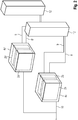
- a charging station 1 having a power-cooling combination component 4c and a charging station 12 according to the present invention is shown schematically.
- the main component 4c is equipped with a power supply module 2a and a cooling module 2b.
- the main component 4c has a first input for a AC power source and AC power line 10.
- the main component 4c also has a first outlet for the coolant line 8 and a second outlet for direct current.
- the charging station further has a charging station 12, which is connected to the main component 4c by means of coolant line 8 and DC line 9. It is hereby advantageously provided a charging station with a charging station.
- the cooling is installed directly in a component with the power supply module.
- FIG. 2 there is shown schematically a charging station 1 with two power supply cooling combination components 4c and 4c 'and two charging stations 12 and 12' according to the present invention.
- a first main component 4c and a second main component 4c 'identical thereto are provided, wherein the first and second main components 4c and 4c' each have a power supply module 2a and 2a 'and a respective cooling module 2b and 2b '.
- the first and second main components 4c and 4c 'each have an input for the same AC source and a first output for a refrigerant line 8 and 8' and a second output for DC.
- the charging station 1 further has a first charging station 12, which is connected to the first main component 4c by means of coolant line 8 and direct current line 9.
- the charging station 1 also has a second charging station 12 ', which is connected to the second main component 4c' by means of the coolant line 8 'and the DC power line 9'. It is hereby advantageously a charging station 1 with two charging columns 12 and 12 'are provided, both of which are fed from the same AC power source. It is hereby advantageously possible, for example, to charge up to two electric vehicles at the same time with electrical energy.
- FIG. 3 a charging station 1 with a power supply component 4a and a cooling component 4b and two charging columns 12 and 12 'according to the present invention is shown schematically.
- a first main component 4a and a second main component 4b are provided.
- the first main component 4a has two power supply modules 2a and 2a ', which are fed via an input for an AC power source with AC.
- the first main component 4a further has an output for direct current.
- the second main component 4b has two cooling modules 2b and 2b 'and a first and a second outlet for a first and a second coolant line 8 and 8'.
- the charging station further comprises a first and a second charging station 12 and 12 ', wherein the first charging station 12 is connected to the first output of the cooling components 4b by means of the first cooling line 8 and the second charging station 12' to the second output of the cooling component 4b 'means the second cooling line 8 'is connected. Only the charging columns 12 and 12 'are cooled by the cooling component 4b. Cooling of the power supply component 4a by the cooling component 4b does not take place.
- the first main component 4a supplies the first and second charging stations 12 and 12 'with direct current by means of a direct current line 9 connected to the first output of the main component 4a and branching into two lines. It is hereby advantageously a charging station 1 with two charging columns 12 and 12 'provided, wherein the cooling can be placed independently of the power supply. It is hereby advantageously possible to take into account in the construction of the charging station 1 local conditions and restrictions.
- FIG. 4 a charging station 1 with two power supply components 4a and 4a ', a cooling component 4b and four charging columns 12, 12', 12 "and 12 '" according to the present invention is shown schematically.
- first, second and third main components 4b, 4a and 4a ' are provided.
- the first main component 4b has two cooling modules 2b and 2b 'with a first and a second outlet for a first and a second coolant line 8 and 8'.
- the second and third main components 4a and 4a 'each have two power supply modules 2a, 2a' and 2a ", 2a '", each with an input for AC and one output for DC.
- the second and third main components 4a and 4a 'each have an inlet for a coolant line 8, by means of which they are connected to the first outlet of the cooling component 4b.
- the charging station 1 also has four charging stations 12, 12 ', 12 "and 12'", which are connected via the second output of the cooling component 4b with a four-way branching cooling line 8 'with the cooling component 4b.
- the cooling component 4b cools both the power supply components 4a and 4a 'and the four charging columns 12, 12', 12 "and 12 '".
- the first power supply component 4a is connected to the DC output of the first power supply component 4a via a branching DC power line 9 to the first and the second charging station 12 and 12 '.
- the second power supply component 4a ' is connected to the DC output of the first power supply component 4a' via a branching DC power line 9 'to the third and the fourth charging column 12 "and 12'".
- the charging station 1 also has a transformation station 11. This supplies the first and the second power supply components 4a and 4a 'via a branching AC line 10 to the AC inputs of the respective main component with alternating current. It is hereby advantageously a charging station 1 with four charging stations 12, 12 ', 12 "and 12'” provided, at the example, up to four electric vehicles can be charged at the same time. Cooling and power supply are advantageously implemented in various main components. While the placement of the power supply components is dependent on the location of the transformation station, the placement of the cooling is not subject to such a limitation. The modular design of the charging station allows flexibility to respond to local conditions and requirements.
- FIG. 5 is a charging station 1 with three power supply components 4a. 4a 'and 4a ", 4b of a cooling component and six charging stations 12, 12', 12", 12 '', 12 IV 12 V and shown schematically according to the present invention.
- the charging station 1 has six charging stations 12, 12 ', 12 ", 12"', 12 IV and 12V.
- the charging station 1 also has a first cooling component 4b, which has a cooling module 2b and an outlet for a coolant line 8.
- the charging station 1 also has a first and a second power supply component 4a and 4a ', wherein the first and the second power supply component 4a and 4a' each have two power supply modules 2a, 2a 'and 2a ", 2a'" and one input for alternating current and one Output for direct current.
- the charging station 1 also has a third power supply component 4a ", which has two power supply modules 2a IV , 2a V and one AC input and one first and one second DC output, and one input for each coolant line.
- the charging station 1 also has a transformation station 11 which is connected to the AC input of the first, second and third power supply components 4a, 4a 'and 4a "respectively via an AC line 10, 10' and 10" respectively.
- the cooling component 4b cools via branching connected to the output of the cooling component 4b Coolant lines 8, the second and third current component 4a 'and 4a "and the six charging columns 12, 12', 12", 12 '", 12 IV and 12 V.
- the first and second charging stations 12 and 12 ' are supplied with direct current via branching from the DC output of the first current component 4a DC line 9.
- the third and fourth charging columns 12 "and 12 '" are supplied with direct current via DC line 9' branching from the DC output of the second current component 4a '.
- the fifth charging station 12 IV is supplied with direct current from the first DC output of the third power supply component 4 a "by means of the DC power line 9".
- the sixth charging station 12 V is supplied with direct current from the second DC output of the third power supply component 4 a "by means of the DC power line 9 '".
- a charging station 1 with six charging stations 12, 12 ', 12 ", 12'", 12 IV and 12 V for simultaneous charging of, for example, up to six electric vehicles available.
Landscapes
- Engineering & Computer Science (AREA)
- Power Engineering (AREA)
- Mechanical Engineering (AREA)
- Transportation (AREA)
- Microelectronics & Electronic Packaging (AREA)
- Physics & Mathematics (AREA)
- Thermal Sciences (AREA)
- Charge And Discharge Circuits For Batteries Or The Like (AREA)
- Electric Propulsion And Braking For Vehicles (AREA)
Abstract
Description
- Die vorliegende Erfindung betrifft ein Ladestationssystem, insbesondere für Elektrofahrzeuge.
- Ladestationssysteme zur Versorgung von Elektrofahrzeugen mit elektrischer Energie sind aus dem Stand der Technik bekannt. Ladestationen sind mit einer oder mehreren Ladeeinheiten ausgestattet. Diese Ladeeinheiten sind üblicherweise als komplette, vorgefertigte Einheit ausgebildet. In einer Einheit finden sich Vorrichtungen zur Stromversorgung, zur Kühlung, Bedienelemente sowie das Ladeanschlusskabel in einer festen Anordnung, Anzahl und Konfiguration. Dabei sind die Ladeeinheiten für einen festen Anwendungsfall und/oder einen bestimmten Einsatzort konstruiert. Neue Anwendungsfälle und/oder Standorte mit gegenüber bisherigen Standorten veränderten Bedingungen erfordern die Planung und den Bau neuer Ladeeinheiten. Es ist mit bisher bekannten Ladestationssystemen nicht möglich, beim Aufbau einer Ladestation flexibel die örtlichen und aktuellen Gegebenheiten und Anforderungen zu berücksichtigen.
- Es ist Aufgabe der vorliegenden Erfindung, ein Ladestationssystem und ein entsprechendes Verfahren zum Aufbau einer solchen Ladestation zur Verfügung zu stellen, das es ermöglicht, beim Aufbau einer Ladestation auf örtliche und aktuelle Anforderungen und Gegebenheiten flexibel zu reagieren.
- Diese Aufgabe wird gelöst durch ein Ladestationssystem, insbesondere für Elektrofahrzeuge, wobei das Ladestationssystem mindestens ein Gehäuse aufweist, wobei das Ladestationssystem eine Mehrzahl an Hauptkomponenten aufweist, dadurch gekennzeichnet, dass das Gehäuse und die Hauptkomponenten so standardisiert sind, dass sich die Hauptkomponenten im Gehäuse modular anordnen lassen.
- Hiermit ist es vorteilhaft möglich beim Aufbau einer Ladestation flexibel auf Standortanforderungen zu reagieren. Insbesondere können die elektrische Leistung und die Kühlleistung der Ladestation unabhängig voneinander gewählt werden. Die elektrische Leistung der Ladestation kann beispielsweise verändert werden, ohne dass die Kühlleistung verändert wird. Umgekehrt kann auch die Kühlleistung der Ladestation verändert werden, ohne dass die elektrische Leistungsfähigkeit der Ladestation verändert wird. Es wird hiermit vorteilhaft ein Ladestationssystem zur Verfügung gestellt, dass eine Skalierung der elektrischen Leistung einer Ladestation unabhängig von der Kühlleistung der Ladestation ermöglicht. Es wird hiermit vorteilhaft ein Ladestationssystem zur Verfügung gestellt, dass eine Skalierung der Kühlleistung einer Ladestation unabhängig von der elektrischen Leistung der Ladestation ermöglicht.
- In einer bevorzugten Ausführungsform der vorliegenden Erfindung, weisen die Hauptkomponenten und das Gehäuse in ihren Maßen eine aufeinander abgestimmte Standardisierung auf, wobei insbesondere das Gehäuse Innenmaße aufweist, die durch die Außenmaße der Hauptkomponenten bestimmt sind.
- In einer bevorzugten Ausführungsform der vorliegenden Erfindung weist das Gehäuse Innenmaße auf, die eine Anordnung mehrerer Hauptkomponenten im Gehäuse unter optimaler Ausnutzung des Volumens des Gehäuses ermöglichen. Insbesondere weist das Gehäuse Innenmaße auf, die sich aus einem ganzzahligen Vielfachen der Außenmaße einer Hauptkomponente und eines zwischen Gehäuse und Hauptkomponente einzuhaltenden Abstandes zusammensetzen. In einer bevorzugten Ausführungsform der vorliegenden Erfindung hat das Gehäuse eine quadratische Grundfläche. In einer weiteren bevorzugten Ausführungsform sind die Außenmaße der Grundfläche des Gehäuses so gewählt, dass das Gehäuse mit der Grundseite auf einer oder mehreren Europaletten platziert werden kann, ohne überzustehen. Europalette im Sinne dieser Erfindung bezeichnet eine nach EN 13698-1 genormte, mehrwegfähige Transportpalette. In einer bevorzugten Ausführungsform der vorliegenden Erfindung weist die Grundfläche des Gehäuses Außenkanten von einer maximalen Länge von 1200 mm auf. In einer alternativen bevorzugten Ausführungsform weist die Grundfläche des Gehäuses Außenkanten von einer maximalen Länge eines ganzzahligen Vielfachen von 1200 mm auf.
- In einer weiteren bevorzugten Ausführungsform der vorliegenden Erfindung, weist das Ladestationssystem eine Mehrzahl an Hauptkomponenten auf, wobei jede dieser Hauptkomponenten einen Schaltschrank aufweist, wobei die Hauptkomponente mindestens ein Modul aufweist, wobei die Architektur des Moduls dadurch gekennzeichnet ist, dass sich das Modul im Schaltschrank modular anordnen lässt.
- In einer bevorzugten Ausführungsform der vorliegenden Erfindung ist der Schaltschrank als 19-Zoll-Rack ausgeführt. Im Sinne der vorliegenden Erfindung bezeichnet ein 19-Zoll-Rack ein nach EIA 310-D, IEC 60297 und DIN 41494 SC48D genormtes Gestell zur Aufnahme elektronischer Vorrichtungen, wobei das Gestell eine genormte Breite von 19 Zoll, d.h. 482,6 mm aufweist, wobei das Gestell weiterhin über Haltevorrichtungen für die elektronischen Vorrichtungen aufweist, die vertikal in einem genormten Abstand von einer Höheneinheit angebracht sind, wobei eine Höheneinheit 1,75 Zoll, d.h. 44,45 mm, entspricht.
- In einer bevorzugten Ausführungsform der vorliegenden Erfindung sind die Außenmaße der Module so gewählt, dass eine Anordnung in einem 19-Zoll-Rack möglich ist.
- Es wird hiermit vorteilhaft eine Hauptkomponente zur Verfügung gestellt, die modular gestaltet werden kann. Es ist hiermit vorteilhaft möglich, Hauptkomponenten mit verschiedenen Eigenschaften schnell und einfach aus vorgegebenen Modulen aufzubauen. Hierdurch ist es vorteilhaft möglich, die Hauptkomponente mit reduziertem Aufwand an neue Gegebenheiten und Anforderungen anzupassen, die sich beispielsweise aus dem Standort und/oder Veränderungen in den technischen Anforderungen und/oder Veränderungen im Konsumentenverhalten ergeben.
- In einer bevorzugten Ausführungsform der vorliegenden Erfindung, weist das Ladestationssystem mindestens eine Hauptkomponente auf, wobei die Hauptkomponente eine Mehrzahl an Modulen aufweist, dadurch gekennzeichnet, dass die Module ausschließlich Stromversorgungsmodule sind.
- Hiermit wird vorteilhaft eine Hauptkomponente zur Verfügung gestellt, die ausschließlich der Stromversorgung dient. Es ist hiermit vorteilhaft möglich, die an die Stromversorgung der Ladestation gestellten Anforderungen und Einschränkungen ohne Rücksicht auf zusätzliche und gegebenenfalls entgegenstehende Anforderungen und Einschränkung anderer Komponenten zu berücksichtigen.
- Beispielsweise ist es Aufgabe der Stromversorgungskomponente, den aus dem stationären Stromnetz bezogenen Wechselstrom in für das Aufladen der Endnutzer, beispielsweise Elektrofahrzeuge, effizienten Gleichstrom umzuwandeln. Dazu wird die Stromversorgungskomponente mit einer Wechselspannungsleitung mit dem stationären Stromnetz verbunden. Dazu wird die Stromversorgungskomponente über eine Gleichspannungsleitung mit einer Ladevorrichtung verbunden. Aufgrund unterschiedlicher technischer Anforderungen können Wechselspannungsleitungen um ein Vielfaches länger ausgeführt werden als Gleichspannungsleitungen. Beispielsweise können Wechselspannungsleitungen eine Länge von bis zu 1000m aufweisen, während Gleichspannungsleitungen eine Länge von bis zu 100m aufweisen können. Die unterschiedliche, technische bedingte Maximallänge von Gleichspannungs- und Wechselstromleitungen stellt eine besondere Anforderung an die Stromversorgungskomponente dar, die aufgrund des modularen Aufbaus des Ladestationssystems vorteilhafterweise ohne Rücksicht auf die Anforderungen an die übrigen Komponenten der Ladestation Rechnung getragen werden kann.
- In einer bevorzugten Ausführungsform der vorliegenden Erfindung weist die Hauptkomponente genau ein Stromversorgungsmodul auf. In einer alternativen bevorzugten Ausführungsform weist die Hauptkomponente mindestens zwei Stromversorgungsmodule auf.
- In einer bevorzugten Ausführungsform der vorliegenden Erfindung weist das Ladestationssystem einen ersten Stromversorgungsmodultyp auf und mindestens einen zweiten Stromversorgungsmodultyp auf, wobei sich der erste und der zweite Stromversorgungsmodultyp in mindestens einer Eigenschaft unterscheiden. In einer bevorzugten Ausführungsform der vorliegenden Erfindung weist der erste Stromversorgungsmodultyp eine erste Architektur auf und der zweite Stromversorgungsmodultyp eine zweite Architektur auf, die von der ersten Architektur verschieden ist. Dabei bezeichnet Architektur im Sinne der vorliegenden Erfindung die Art und Anordnung der elektrischen Bauteile, aus der das Stromversorgungsmodul zusammengesetzt ist.
- Im Sinne der vorliegenden Erfindung sind Bauteile beispielsweise, aber nicht ausschließlich Einheiten zur Umwandlung von Wechselstrom in Gleichstrom (AC/DC units) und Einheiten zur Umwandlung von Gleichstrom in Gleichstrom (DC/DC units) in beliebiger Ausführung.
- In einer bevorzugten Ausführungsform der vorliegenden Erfindung, weist das Ladestationssystem mindestens eine Hauptkomponente auf, wobei die Hauptkomponente eine Mehrzahl an Modulen aufweist, dadurch gekennzeichnet, dass die Hauptkomponente mindestens ein Stromversorgungsmodul und ein Kühlmodul aufweist.
- Es wird hiermit vorteilhaft eine Hauptkomponente zur Verfügung gestellt, die Kühlung und Stromversorgung kombiniert. Eine Hauptkomponente, die mindestens ein Kühlmodul und mindestens ein Stromversorgungsmodul aufweist, wird im Folgenden als Stromversorgungs-Kühl-Kombinationskomponente bezeichnet.
- In einer bevorzugten Ausführungsform der vorliegenden Erfindung, weist das Ladestationssystem mindestens eine Hauptkomponente auf, wobei die Hauptkomponente eine Mehrzahl an Modulen aufweist, dadurch gekennzeichnet, dass die Module ausschließlich Kühlmodule sind.
Hiermit wird vorteilhaft eine Hauptkomponente allein zur Kühlung zur Verfügung gestellt. Es ist hiermit vorteilhaft möglich, die an die Kühlung der Ladestation gestellten Anforderungen und Einschränkungen ohne Rücksicht auf zusätzliche und gegebenenfalls entgegenstehende Anforderungen und Einschränkung anderer Komponenten, zu berücksichtigen. - In einer bevorzugten Ausführungsform der vorliegenden Erfindung weist die Hauptkomponente genau ein Kühlmodul auf. In einer alternativen bevorzugten Ausführungsform weist die Hauptkomponente mindestens zwei Kühlmodule auf.
- In einer bevorzugten Ausführungsform der vorliegenden Erfindung weist das Ladestationssystem einen ersten Kühlmodultyp auf und mindestens einen zweiten Kühlmodultyp auf, wobei sich der erste und der zweite Kühlmodultyp in mindestens einer Eigenschaft unterscheiden. In einer bevorzugten Ausführungsform der vorliegenden Erfindung weist der erste Kühlmodultyp eine erste Kühlleistung auf und der zweite Kühlmodultyp eine zweite Kühlleistung auf, die von der ersten Kühlleistung verschieden ist.
- In einer bevorzugten Ausführungsform der vorliegenden Erfindung, weist das Ladestationssystem eine Ladesäule auf. In einer bevorzugten Ausführungsform der vorliegenden Erfindung weist die Ladesäule Bedienelemente zur Bedienung durch einen Nutzer der Ladesäule auf.
- In einer bevorzugten Ausführungsform der vorliegenden Erfindung, weist das Ladestationssystem eine Transformationsstation auf.
- In einer bevorzugten Ausführungsform der vorliegenden Erfindung, ist das mindestens eine Gehäuse aus Stahlblech, Stahlplatten oder Beton gefertigt ist.
Es wird hiermit vorteilhaft ein Gehäuse zur Verfügung gestellt, das im Freien sowie in Gebäuden aufstellbar ist. - In einer bevorzugten Ausführungsform der vorliegenden Erfindung, weist das mindestens eine Gehäuse genau eine Tür auf. Es ist hiermit vorteilhaft möglich, nach dem Aufstellen des mit Hauptkomponenten bestückten Gehäuses die Hauptkomponenten auszutauschen und/oder Reparaturen und/oder Wartungsarbeiten an den Hauptkomponenten und deren Leitungen vorzunehmen, ohne das Gehäuse zu beschädigen.
- In einer bevorzugten Ausführungsform der vorliegenden Erfindung, weist das Ladestationssystem ein erstes Gehäuse und mindestens ein neben oder über dem ersten Gehäuse befindliches, zweites Gehäuse auf.
- Es wird hiermit vorteilhaft ein Ladestationssystem zur Verfügung gestellt, dessen Gehäuse sich neben- und/oder aufeinanderstapeln lassen. Es ist hiermit vorteilhaft möglich, den zur Unterbringung der Hauptkomponenten vorhandenen Innenraum zu vergrößern.
- Weitere Einzelheiten, Merkmale und Vorteile der Erfindung ergeben sich aus den Zeichnungen sowie aus der nachfolgenden Beschreibung von bevorzugten Ausführungsformen anhand der Zeichnungen. Die Zeichnungen illustrieren dabei lediglich beispielhafte Ausführungsformen der Erfindung, welche den Erfindungsgedanken nicht einschränken.
-
Figur 1 illustriert schematisch den Aufbau einer Ladestation mit einer Ladesäule und einer Stromversorgungs-Kühl-Kombinationskomponente. -
Figur 2 illustriert schematisch den Aufbau einer Ladestation mit zwei Ladesäulen und zwei Stromversorgungs-Kühl-Kombinationskomponenten. -
Figur 3 illustriert schematisch den Aufbau einer Ladestation mit zwei Ladesäulen und einer Stromversorgungskomponente und einer Kühlkomponente. -
Figur 4 illustriert schematisch den Aufbau einer Ladestation mit vier Ladesäulen und zwei Stromversorgungskomponenten und einer Kühlkomponente, sowie einer Transformationsstation. -
Figur 5 illustriert schematisch den Aufbau einer Ladestation mit sechs Ladesäulen und drei Stromversorgungskomponenten und einer Kühlkomponente, sowie einer Transformationsstation. - In
Figur 1 ist eine Ladestation 1 mit einer Stromversorgungs-Kühl-Kombinationskomponente 4c und einer Ladesäule 12 gemäß der vorliegenden Erfindung schematisch dargestellt.
In einer bevorzugten Ausführungsform der vorliegenden Erfindung, ist die Hauptkomponente 4c mit einem Stromversorgungsmodul 2a und einem Kühlmodul 2b ausgestattet. Die Hauptkomponente 4c weist einen ersten Eingang für eine Wechselstromquelle und Wechselstromleitung 10 auf. Die Hauptkomponente 4c weist ferner einen ersten Ausgang für die Kühlmittelleitung 8 und einen zweiten Ausgang für Gleichstrom auf. Die Ladestation weist ferner eine Ladesäule 12 auf, die mit der Hauptkomponente 4c mittels Kühlmittelleitung 8 und Gleichstromleitung 9 verbunden ist. Es wird hiermit vorteilhaft eine Ladestation mit einer Ladesäule zur Verfügung gestellt. Vorteilhaft ist die Kühlung direkt in einer Komponente mit dem Stromversorgungsmodul verbaut. - In
Figur 2 ist eine Ladestation 1 mit zwei Stromversorgungs-Kühl-Kombinationskomponenten 4c und 4c' und zwei Ladesäulen 12 und 12' gemäß der vorliegenden Erfindung schematisch dargestellt.
In einer alternativen bevorzugten Ausführungsform der vorliegenden Erfindung, werden eine erste Hauptkomponente 4c und eine zu dieser identische zweite Hauptkomponente 4c' zur Verfügung gestellt, wobei die erste und die zweite Hauptkomponente 4c und 4c' jeweils ein Stromversorgungsmodul 2a und 2a' und jeweils ein Kühlmodul 2b und 2b' aufweisen. Die erste und die zweite Hauptkomponente 4c und 4c' weisen jeweils einen Eingang für dieselbe Wechselstromquelle und einen ersten Ausgang für eine Kühlmittelleitung 8 und 8' und einen zweiten Ausgang für Gleichstrom auf. Die Ladestation 1 weist ferner eine erste Ladesäule 12 auf, die mit der ersten Hauptkomponente 4c mittels Kühlmittelleitung 8 und Gleichstromleitung 9 verbunden ist. Die Ladestation 1 weist ferner eine zweite Ladesäule 12' auf, die mit der zweiten Hauptkomponente 4c' mittels Kühlmittelleitung 8' und Gleichstromleitung 9' verbunden ist.
Es wird hiermit vorteilhaft eine Ladestation 1 mit zwei Ladesäulen 12 und 12' zur Verfügung gestellt, die beide aus derselben Wechselstromquelle gespeist werden. Es ist hiermit vorteilhaft möglich, beispielsweise bis zu zwei Elektrofahrzeuge gleichzeitig mit elektrischer Energie aufzuladen. - In
Figur 3 ist eine Ladestation 1 mit einer Stromversorgungskomponente 4a und einer Kühlkomponente 4b und zwei Ladesäulen 12 und 12' gemäß der vorliegenden Erfindung schematisch dargestellt. - In einer alternativen bevorzugten Ausführungsform der vorliegenden Erfindung, werden eine erste Hauptkomponente 4a und eine zweite Hauptkomponente 4b zur Verfügung gestellt. Die erste Hauptkomponente 4a weist zwei Stromversorgungsmodule 2a und 2a' auf, die über einen Eingang für eine Wechselstromquelle mit Wechselstrom gespeist werden. Die erste Hauptkomponente 4a weist ferner einen Ausgang für Gleichstrom auf. Die zweite Hauptkomponente 4b weist zwei Kühlmodule 2b und 2b' und einen ersten und einen zweiten Ausgang für eine erste und eine zweite Kühlmittelleitung 8 und 8' auf. Die Ladestation weist ferner eine erste und eine zweite Ladesäule 12 und 12' auf, wobei die erste Ladesäule 12 mit dem ersten Ausgang der Kühlkomponenten 4b mittels der ersten Kühlleitung 8 verbunden ist und die zweite Ladesäule 12' mit dem zweiten Ausgang der Kühlkomponente 4b' mittels der zweiten Kühlleitung 8' verbunden ist. Es werden nur die Ladesäulen 12 und 12' durch die Kühlkomponente 4b gekühlt. Eine Kühlung der Stromversorgungskomponente 4a durch die Kühlkomponente 4b findet nicht statt. Die erste Hauptkomponente 4a versorgt die erste und die zweite Ladesäule 12 und 12' mit Gleichstrom mittels einer mit dem ersten Ausgang der Hauptkomponente 4a verbundenen, sich in zwei Leitungen verzweigenden Gleichstromleitung 9.
Es wird hiermit vorteilhaft eine Ladestation 1 mit zwei Ladesäulen 12 und 12' zur Verfügung gestellt, wobei die Kühlung unabhängig von der Stromversorgung platziert werden kann. Es ist hiermit vorteilhaft möglich, beim Aufbau der Ladestation 1 örtliche Gegebenheiten und Beschränkungen zu berücksichtigen. - In
Figur 4 ist eine Ladestation 1 mit zwei Stromversorgungskomponenten 4a und 4a', einer Kühlkomponente 4b und vier Ladesäulen 12, 12', 12" und 12'" gemäß der vorliegenden Erfindung schematisch dargestellt.
In einer weiteren alternativen Ausführungsform der vorliegenden Erfindung, werden eine erste, eine zweite und eine dritte Hauptkomponente 4b, 4a und 4a' zur Verfügung gestellt. Dabei weist die erste Hauptkomponente 4b zwei Kühlmodule 2b und 2b' mit einem ersten und einem zweiten Ausgang für eine erste und eine zweite Kühlmittelleitung 8 und 8' auf. Die zweite und die dritte Hauptkomponente 4a und 4a' weisen jeweils zwei Stromversorgungsmodule 2a, 2a' und 2a", 2a'" mit jeweils einem Eingang für Wechselstrom und jeweils einen Ausgang für Gleichstrom auf. Die zweite und die dritte Hauptkomponente 4a und 4a' weisen jeweils einen Eingang für eine Kühlmittelleitung 8 auf, mittels derer sie mit dem ersten Ausgang der Kühlkomponente 4b verbunden sind. Die Ladestation 1 weist ferner vier Ladesäulen 12, 12', 12" und 12'" auf, die über den zweiten Ausgang der Kühlkomponente 4b mit einer sich vierfach verzweigenden Kühlleitung 8' mit der Kühlkomponente 4b verbunden sind. Die Kühlkomponente 4b kühlt sowohl die Stromversorgungskomponenten 4a und 4a' als auch die vier Ladesäulen 12, 12', 12" und 12'". Die erste Stromversorgungskomponente 4a ist am Gleichstromausgang der ersten Stromversorgungskomponente 4a über eine sich verzweigende Gleichstromleitung 9 mit der ersten und der zweiten Ladesäule 12 und 12' verbunden. Die zweite Stromversorgungskomponente 4a' ist am Gleichstromausgang der ersten Stromversorgungskomponente 4a' über eine sich verzweigende Gleichstromleitung 9' mit der dritten und der vierten Ladesäule 12" und 12'" verbunden. Die Ladestation 1 weist ferner eine Transformationsstation 11 auf. Diese versorgt die erste und die zweite Stromversorgungskomponente 4a und 4a' über eine sich verzweigende Wechselstromleitung 10 zu den Wechselstromeingängen der jeweiligen Hauptkomponente mit Wechselstrom.
Es wird hiermit vorteilhaft eine Ladestation 1 mit vier Ladesäulen 12, 12', 12" und 12'" zur Verfügung gestellt, an der beispielsweise bis zu vier Elektrofahrzeuge gleichzeitig aufgeladen werden können. Vorteilhaft sind Kühlung und Stromversorgung in verschiedenen Hauptkomponenten umgesetzt. Während die Platzierung der Stromversorgungskomponenten von dem Ort der Transformationsstation abhängt, unterliegt die Platzierung der Kühlung keiner solchen Beschränkung. Der modulare Aufbau der Ladestation erlaubt auch hier, auf die örtlichen Gegebenheiten und Anforderungen flexibel einzugehen. - In
Figur 5 ist eine Ladestation 1 mit drei Stromversorgungskomponenten 4a. 4a' und 4a", einer Kühlkomponente 4b und sechs Ladesäulen 12, 12', 12", 12'", 12IV und 12V gemäß der vorliegenden Erfindung schematisch dargestellt. - In einer weiteren bevorzugten Ausführungsform der vorliegenden Erfindung, weist die Ladestation 1 sechs Ladesäulen 12, 12', 12", 12"', 12IV und 12V auf. Die Ladestation 1 weist ferner eine erste Kühlkomponente 4b auf, die ein Kühlmodul 2b und einen Ausgang für eine Kühlmittelleitung 8 aufweist, auf. Die Ladestation 1 weist ferner eine erste und eine zweite Stromversorgungskomponente 4a und 4a' auf, wobei die erste und die zweite Stromversorgungskomponente 4a und 4a' jeweils zwei Stromversorgungsmodule 2a, 2a' und 2a", 2a'" und jeweils einen Eingang für Wechselstrom und einen Ausgang für Gleichstrom aufweisen. Die Ladestation 1 weist weiterhin eine dritte Stromversorgungskomponente 4a" auf, die zwei Stromversorgungsmodule 2aIV, 2aV und einen Wechselstromeingang und einen ersten und einen zweiten Gleichstromausgang, sowie einen jeweils einen Eingang für jeweils eine Kühlmittelleitung aufweist. Die Ladestation 1 weist ferner eine Transformationsstation 11 auf, die über je eine Wechselstromleitung 10, 10' und 10" jeweils mit dem Wechselstromeingang der ersten, zweiten und dritten Stromversorgungskomponente 4a, 4a' und 4a" verbunden ist. Die Kühlkomponente 4b kühlt über mit dem Ausgang der Kühlkomponente 4b verbundenen, sich verzweigenden Kühlmittelleitungen 8 die zweite und dritte Stromkomponente 4a' und 4a" sowie die sechs Ladesäulen 12, 12', 12", 12'", 12IV und 12V. Die erste und zweite Ladesäule 12 und 12' werden über aus dem Gleichstromausgang der ersten Stromkomponente 4a sich verzweigenden Gleichstromleitung 9 mit Gleichstrom versorgt. Die dritte und vierte Ladesäule 12" und 12'" werden über aus dem Gleichstromausgang der zweiten Stromkomponente 4a' sich verzweigenden Gleichstromleitung 9' mit Gleichstrom versorgt. Die fünfte Ladesäule 12IV wird aus dem ersten Gleichstromausgang der dritten Stromversorgungskomponente 4a" mittels der Gleichstromleitung 9" mit Gleichstrom versorgt. Die sechste Ladesäule 12V wird aus dem zweiten Gleichstromausgang der dritten Stromversorgungskomponente 4a" mittels der Gleichstromleitung 9'" mit Gleichstrom versorgt.
- Es wird hiermit vorteilhaft eine Ladestation 1 mit sechs Ladesäulen 12, 12', 12", 12'", 12IV und 12V zum gleichzeitigen Aufladen von beispielsweise bis zu sechs Elektrofahrzeugen zur Verfügung gestellt.
-
- 1
- Ladestation
- 2a
- Stromversorgungsmodul
- 2b
- Kühlmodul
- 4a
- Stromversorgungskomponente
- 4b
- Kühlkomponente
- 4c
- Stromversorgungs-Kühl-Kombinationskomponente
- 7
- Gehäuse
- 8
- Kühlmittelleitung
- 9
- Gleichstromleitung
- 10
- Wechselstromleitung
- 11
- Transformationsstation
- 12
- Ladesäule
Claims (13)
- Ladestationssystem, insbesondere für Elektrofahrzeuge, wobei das Ladestationssystem mindestens ein Gehäuse (7) aufweist, wobei das Ladestationssystem eine Mehrzahl an Hauptkomponenten (4) aufweist, dadurch gekennzeichnet, dass das Gehäuse (7) und die Hauptkomponenten (4) so standardisiert sind, dass sich die Hauptkomponenten (4) im Gehäuse (7) modular anordnen lassen.
- Ladestationssystem nach Anspruch 1, wobei die Hauptkomponenten (4) und das Gehäuse (7) in ihren Maßen eine aufeinander abgestimmte Standardisierung aufweisen, wobei insbesondere das Gehäuse (7) Innenmaße aufweist, die durch die Außenmaße der Hauptkomponenten (4) bestimmt sind.
- Ladestationssystem nach einem der vorhergehenden Ansprüche, wobei das Ladestationssystem eine Mehrzahl an Hauptkomponenten (4) aufweist, wobei jede dieser Hauptkomponenten einen Schaltschrank aufweist, wobei die Hauptkomponente (4) mindestens ein Modul (2) aufweist, wobei die Architektur des Moduls (2) dadurch gekennzeichnet ist, dass sich das Modul (2) im Schaltschrank modular anordnen lässt.
- Ladestationssystem nach Anspruch 3, wobei das Ladestationssystem mindestens eine Hauptkomponente (4) aufweist, wobei die Hauptkomponente (4) eine Mehrzahl an Modulen (2) aufweist, dadurch gekennzeichnet, dass die Module (2) ausschließlich Stromversorgungsmodule (2a) sind.
- Ladestation nach einem der vorhergehenden Ansprüche, wobei das Ladestationssystem mindestens eine Hauptkomponente (4) aufweist, wobei die Hauptkomponente (4) eine Mehrzahl an Modulen (2) aufweist, dadurch gekennzeichnet, dass die Hauptkomponente (4) mindestens ein Stromversorgungsmodul (2a) und ein Kühlmodul (2b) aufweist.
- Ladestation nach einem der vorhergehenden Ansprüche, wobei das Ladestationssystem mindestens eine Hauptkomponente (4) aufweist, wobei die Hauptkomponente (4) eine Mehrzahl an Modulen (2) aufweist, dadurch gekennzeichnet, dass die Module (2) ausschließlich Kühlmodule (2b) sind.
- Ladestationssystem nach einem der vorhergehenden Ansprüche, wobei das Ladestationssystem eine Ladesäule (12) aufweist.
- Ladestationssystem nach einem der vorhergehenden Ansprüche, wobei das Ladestationssystem eine Transformationsstation (11) aufweist.
- Ladestationssystem nach einem der vorhergehenden Ansprüche, wobei das mindestens eine Gehäuse (7) aus Stahlblech, Stahlplatten oder Beton gefertigt ist.
- Ladestationssystem nach einem der vorhergehenden Ansprüche, wobei das mindestens eine Gehäuse (7) genau eine Tür aufweist.
- Ladestationssystem nach einem der vorhergehenden Ansprüche, wobei das Ladestationssystem ein erstes Gehäuse (7) und mindestens ein neben oder über dem ersten Gehäuse (7) befindliches, zweites Gehäuse (7) aufweist.
- Verfahren zum Aufbau einer Ladestation nach einem der vorhergehenden Ansprüche, insbesondere für Elektrofahrzeuge, wobei in einem ersten Schritt mindestens ein standardisiertes Gehäuse (7) zur Verfügung gestellt wird, wobei in einem zweiten Schritt das mindestens eine standardisierte Gehäuse (7) mit einer ersten standardisierten Hauptkomponente (4) und mindestens einer zweiten standardisierten Hauptkomponente (4) modular bestückt wird und wobei in einem dritten Schritt die erste standardisierte Hauptkomponente (4) mit der zweiten standardisierten Hauptkomponente (4) verbunden wird.
- Verfahren nach Anspruch 14, wobei in einem ersten Schritt ein erstes und ein zweites mit je mindestens einer standardisierten Hauptkomponente (4) bestücktes, standardisiertes Gehäuse (7) zur Verfügung gestellt wird, wobei in einem zweiten Schritt das erste standardisierte Gehäuse (7) neben oder auf dem zweiten standardisierten Gehäuse (7) aufgestellt wird und wobei in einem dritten Schritt das erste standardisierte Gehäuse (7) mit dem zweiten standardisierten Gehäuse (7) verbunden wird.
Applications Claiming Priority (1)
| Application Number | Priority Date | Filing Date | Title |
|---|---|---|---|
| DE102017105632.7A DE102017105632A1 (de) | 2017-03-16 | 2017-03-16 | Ladestationssystem für Elektrofahrzeuge |
Publications (2)
| Publication Number | Publication Date |
|---|---|
| EP3375658A2 true EP3375658A2 (de) | 2018-09-19 |
| EP3375658A3 EP3375658A3 (de) | 2018-12-26 |
Family
ID=61002820
Family Applications (1)
| Application Number | Title | Priority Date | Filing Date |
|---|---|---|---|
| EP18020024.8A Pending EP3375658A3 (de) | 2017-03-16 | 2018-01-16 | Ladestationssystem für elektrofahrzeuge |
Country Status (6)
| Country | Link |
|---|---|
| US (1) | US10457153B2 (de) |
| EP (1) | EP3375658A3 (de) |
| JP (1) | JP6655112B2 (de) |
| CN (1) | CN108622035B (de) |
| DE (1) | DE102017105632A1 (de) |
| NO (1) | NO346065B1 (de) |
Families Citing this family (7)
| Publication number | Priority date | Publication date | Assignee | Title |
|---|---|---|---|---|
| DE102016105347A1 (de) * | 2016-03-22 | 2017-09-28 | Phoenix Contact E-Mobility Gmbh | Steckverbinderteil mit einem gekühlten Kontaktelement |
| DE102016105311A1 (de) * | 2016-03-22 | 2017-09-28 | Phoenix Contact E-Mobility Gmbh | Steckverbinderteil mit einem gekühlten Kontaktelement |
| DE102017110703B4 (de) * | 2017-05-17 | 2024-03-28 | Dr. Ing. H.C. F. Porsche Aktiengesellschaft | Kühlvorrichtung und Verfahren zum Betreiben einer Mehrzahl von Ladestationen |
| CN112004712A (zh) * | 2018-04-20 | 2020-11-27 | 西门子股份公司 | 充电基础设施单元和具有充电功率选项的充电基础设施 |
| US11285832B2 (en) * | 2019-06-05 | 2022-03-29 | TE Connectivity Services Gmbh | Heat exchanger for a power connector |
| CN113315183B (zh) * | 2020-02-27 | 2025-06-06 | 台达电子企业管理(上海)有限公司 | 充电桩及其功率分配系统与功率分配方法 |
| PL247941B1 (pl) | 2024-05-31 | 2025-09-15 | Ekoenergetyka Polska Spolka Akcyjna | Układ chłodzenia i odzysku ciepła odpadowego ze stacji ładowania oraz sposób chłodzenia i odzysku ciepła odpadowego ze stacji ładowania |
Citations (3)
| Publication number | Priority date | Publication date | Assignee | Title |
|---|---|---|---|---|
| US20100060093A1 (en) * | 2008-08-14 | 2010-03-11 | F3 & I2, Llc | Power packaging with railcars |
| EP2212203B1 (de) * | 2007-10-31 | 2012-07-11 | Illinois Tool Works Inc. | Bodenfahrzeug eines flugzeuges mit diskretem generator, stromrichter- und klimatisierungsmodulen |
| CN105896678A (zh) * | 2016-06-02 | 2016-08-24 | 广东中研能源有限公司 | 一种可调整电源转换功率的大功率充电桩 |
Family Cites Families (26)
| Publication number | Priority date | Publication date | Assignee | Title |
|---|---|---|---|---|
| US4992669A (en) | 1989-02-16 | 1991-02-12 | Parmley Daniel W | Modular energy system |
| US5548200A (en) * | 1994-07-06 | 1996-08-20 | Norvik Traction Inc. | Universal charging station and method for charging electric vehicle batteries |
| US5847537A (en) * | 1996-10-19 | 1998-12-08 | Parmley, Sr.; Daniel W. | Electric vehicle charging station system |
| JP2003007356A (ja) | 2001-06-25 | 2003-01-10 | Matsushita Refrig Co Ltd | 蓄電池の温度調節装置とそれを搭載した移動車 |
| JP4491434B2 (ja) * | 2006-05-29 | 2010-06-30 | トヨタ自動車株式会社 | 電力制御装置およびそれを備えた車両 |
| US8368351B2 (en) * | 2008-04-09 | 2013-02-05 | Qualcomm Incorporated | Transmission line directional awareness for a charging station |
| US7619319B1 (en) | 2008-07-15 | 2009-11-17 | F3 & I2, Llc | Network of energy generating modules for transfer of energy outputs |
| JPWO2011118187A1 (ja) * | 2010-03-23 | 2013-07-04 | パナソニック株式会社 | 充電制御装置、充電システムおよび充電制御方法 |
| NL2004746C2 (en) * | 2010-05-19 | 2011-11-22 | Epyon B V | Charging system for electric vehicles. |
| DE102010041766A1 (de) * | 2010-09-30 | 2012-04-05 | Siemens Aktiengesellschaft | Ladesystem für Elektrofahrzeuge |
| US8680812B2 (en) * | 2011-03-09 | 2014-03-25 | General Electric Company | Methods and systems for charging an electric vehicle |
| DE102011007839A1 (de) * | 2011-04-21 | 2012-10-25 | Bayerische Motoren Werke Aktiengesellschaft | Fahrzeugladevorrichtung |
| US9786961B2 (en) * | 2011-07-25 | 2017-10-10 | Lightening Energy | Rapid charging electric vehicle and method and apparatus for rapid charging |
| FR2978624B1 (fr) * | 2011-07-29 | 2013-12-20 | Evtronic | Installation et procede de charge pour batterie electrique |
| US9561731B2 (en) * | 2011-12-13 | 2017-02-07 | Brightfield Transportation Solutions, Inc. | Structural bollard assembly for electric vehicle infrastructure |
| US9096141B2 (en) | 2012-04-10 | 2015-08-04 | Go-Tech Energy Co. Ltd. | Detachable modularized battery charging assembly |
| CN202721474U (zh) * | 2012-08-16 | 2013-02-06 | 石家庄金硕电子科技有限公司 | 集中式蓄电池维护柜 |
| KR20140050973A (ko) * | 2012-10-22 | 2014-04-30 | 현대중공업 주식회사 | 모듈형 igbt를 이용한 고속전철용 추진제어장치의 전력스택 |
| US8872366B2 (en) | 2013-01-31 | 2014-10-28 | APR Energy, LLC | Scalable portable modular power plant |
| JP2014230301A (ja) * | 2013-05-17 | 2014-12-08 | 株式会社エネルギー応用技術研究所 | 急速充電用電力供給システム |
| BR202013029267U2 (pt) | 2013-11-13 | 2015-10-27 | Aruanã En S A | disposição construtiva introduzida em usina elétrica modular dotada de sistema de transformador de alta tensão para conexão direta em sistema de distribuição de energia integrados em contêineres ou similares |
| US9630513B2 (en) * | 2014-03-11 | 2017-04-25 | Bayerische Motoren Werke Aktiengesellschaft | Portable bi-directional multiport AC/DC charging cable system |
| JP2016063690A (ja) * | 2014-09-19 | 2016-04-25 | 日立マクセル株式会社 | 蓄電システム |
| EP3035478B1 (de) * | 2014-12-18 | 2020-05-06 | Compleo Charging Solutions GmbH | Ladestation zum bereitstellen elektrischer energie für ein elektrisch betreibbares fahrzeug und die ladestation aufweisende ladeinstallationsanordnung |
| US9819060B2 (en) * | 2015-07-31 | 2017-11-14 | Gerard O'Hora | Portable and modular energy storage with adjustable waveform characteristics for electric vehicles |
| WO2017066790A1 (en) * | 2015-10-16 | 2017-04-20 | California Intitute Of Technology | Adaptive charging algorithms for a network of electric vehicles |
-
2017
- 2017-03-16 DE DE102017105632.7A patent/DE102017105632A1/de active Pending
-
2018
- 2018-01-16 EP EP18020024.8A patent/EP3375658A3/de active Pending
- 2018-03-05 NO NO20180324A patent/NO346065B1/en unknown
- 2018-03-14 CN CN201810210176.8A patent/CN108622035B/zh active Active
- 2018-03-15 US US15/922,035 patent/US10457153B2/en active Active
- 2018-03-15 JP JP2018047677A patent/JP6655112B2/ja active Active
Patent Citations (3)
| Publication number | Priority date | Publication date | Assignee | Title |
|---|---|---|---|---|
| EP2212203B1 (de) * | 2007-10-31 | 2012-07-11 | Illinois Tool Works Inc. | Bodenfahrzeug eines flugzeuges mit diskretem generator, stromrichter- und klimatisierungsmodulen |
| US20100060093A1 (en) * | 2008-08-14 | 2010-03-11 | F3 & I2, Llc | Power packaging with railcars |
| CN105896678A (zh) * | 2016-06-02 | 2016-08-24 | 广东中研能源有限公司 | 一种可调整电源转换功率的大功率充电桩 |
Non-Patent Citations (2)
| Title |
|---|
| HANS ROBERT KOCH: "K�hlsystem LCP Industrie von Rittal weiterentwickelt", 12 July 2016 (2016-07-12), https://www.ke-next.de/automation/elektrotechnik/kuehl-system-lcp-industrie-von-rittal-weiterentwickelt-111.html, XP055763742, Retrieved from the Internet <URL:https://www.ke-next.de/automation/elektrotechnik/kuehl-system-lcp-industrie-von-rittal-weiterentwickelt-111.html> [retrieved on 20210112] * |
| SETEC-POWER.COM: "Solar EV charging station used EV fast charger with CHAdeMO and SAE combo connector, View CHAdeMO EV charging station, SETEC Product Details from Shenzhen Setec Power Co., Ltd. on Alibaba.com", 14 August 2015 (2015-08-14), XP055487382, Retrieved from the Internet <URL:https://inverter.en.alibaba.com/product/60438630382-801471302/Solar_EV_charging_station_used_EV_fast_charger_with_CHAdeMO_and_SAE_combo_connector.html> [retrieved on 20180625] * |
Also Published As
| Publication number | Publication date |
|---|---|
| DE102017105632A1 (de) | 2018-09-20 |
| CN108622035A (zh) | 2018-10-09 |
| JP6655112B2 (ja) | 2020-02-26 |
| CN108622035B (zh) | 2022-01-14 |
| NO346065B1 (en) | 2022-01-31 |
| NO20180324A1 (en) | 2018-09-17 |
| US20180264962A1 (en) | 2018-09-20 |
| EP3375658A3 (de) | 2018-12-26 |
| JP2018157748A (ja) | 2018-10-04 |
| US10457153B2 (en) | 2019-10-29 |
Similar Documents
| Publication | Publication Date | Title |
|---|---|---|
| EP3375658A2 (de) | Ladestationssystem für elektrofahrzeuge | |
| EP3428000B1 (de) | Vorrichtung zum laden mindestens einer batterie | |
| DE102017207102A1 (de) | Stationärspeicher zum Zwischenspeichern von elektrischer Energie in einem elektrischen Versorgungsnetz sowie Betriebsverfahren und Nachrüstmodul für den Stationärspeicher | |
| DE102015110023A1 (de) | Ladestation und Verfahren zum Laden eines Plug-In-Kraftfahrzeuges an einer Ladesäule | |
| EP3501884A1 (de) | Transformatorvorrichtung für eine ladestation für das elektrische laden von fahrzeugen mit wenigstens zwei ladepunkten | |
| DE102019124212A1 (de) | Entmagnetisierung des Rotors einer fremderregten Synchronmaschine | |
| DE102020102518A1 (de) | Ladesäule | |
| DE102018113174A1 (de) | Universelles Ladegerät für Gleich- und Wechselstromladen | |
| DE102013204255A1 (de) | Verfahren und Vorrichtung zum Betreiben eines Bordnetzes | |
| DE202017104921U1 (de) | Antriebsvorrichtung für ein Funktionsfahrzeug | |
| DE102013109555A1 (de) | Modularer Isolator zur Sammelschienenabstützung und Montageverfahren | |
| EP3471235A2 (de) | Energiebereitstellungseinrichtung zum bereitstellen elektrischer energie für ein kraftfahrzeug sowie verfahren zum betreiben einer energiebereitstellungseinrichtung | |
| DE102022131125A1 (de) | Flexibles aufteilbares DC-Ladesystem | |
| WO2017008927A1 (de) | Vorrichtung und verfahren zur induktiven übertragung elektrischer energie zu beweglichen elektrischen verbrauchern | |
| DE202018100340U1 (de) | Anordnung zur Ausbildung von Gleichspannungsladestationen mit einem oder mehreren Ladepunkten zur Gleichstromschnellladung | |
| DE102021121127A1 (de) | Verfahren zum Betreiben eines Netzmanagementsystems für ein lokales Energienetz, Computerprogrammprodukt sowie Netzmanagementsystem | |
| DE102021108037A1 (de) | Elektrische Leistungssteuereinheit und Ladestation | |
| DE112024002612T5 (de) | Skalierbares und tragbares ws/gs-umspannwerk | |
| DE102019200875A1 (de) | Hochvoltbatterieeinheit für ein Elektrofahrzeug | |
| DE202023103356U1 (de) | Gleichstrom-Niederspannungs-Verteilungssystem | |
| DE102013105649A1 (de) | Energiespeichersystem | |
| WO2021209183A1 (de) | Energieaustausch zwischen lanes von elektrischen multi-lane-antrieben | |
| EP3172494B1 (de) | Verfahren zum kühlen und anordnung aus luftkonditionierungsgerät und wärmeerzeugenden geräten | |
| DE202015009840U1 (de) | Ladestation zum Laden eines Plug-In-Kraftfahrzeuges an einer Ladesäule | |
| DE202023105809U1 (de) | Kompaktes AC-DC-Wandler-System zur Bereitstellung mehrerer Hochspannungen |
Legal Events
| Date | Code | Title | Description |
|---|---|---|---|
| PUAI | Public reference made under article 153(3) epc to a published international application that has entered the european phase |
Free format text: ORIGINAL CODE: 0009012 |
|
| STAA | Information on the status of an ep patent application or granted ep patent |
Free format text: STATUS: THE APPLICATION HAS BEEN PUBLISHED |
|
| AK | Designated contracting states |
Kind code of ref document: A2 Designated state(s): AL AT BE BG CH CY CZ DE DK EE ES FI FR GB GR HR HU IE IS IT LI LT LU LV MC MK MT NL NO PL PT RO RS SE SI SK SM TR |
|
| AX | Request for extension of the european patent |
Extension state: BA ME |
|
| PUAL | Search report despatched |
Free format text: ORIGINAL CODE: 0009013 |
|
| AK | Designated contracting states |
Kind code of ref document: A3 Designated state(s): AL AT BE BG CH CY CZ DE DK EE ES FI FR GB GR HR HU IE IS IT LI LT LU LV MC MK MT NL NO PL PT RO RS SE SI SK SM TR |
|
| AX | Request for extension of the european patent |
Extension state: BA ME |
|
| RIC1 | Information provided on ipc code assigned before grant |
Ipc: H02J 7/00 20060101ALI20181121BHEP Ipc: B60L 11/18 20060101AFI20181121BHEP |
|
| STAA | Information on the status of an ep patent application or granted ep patent |
Free format text: STATUS: REQUEST FOR EXAMINATION WAS MADE |
|
| 17P | Request for examination filed |
Effective date: 20190626 |
|
| RBV | Designated contracting states (corrected) |
Designated state(s): AL AT BE BG CH CY CZ DE DK EE ES FI FR GB GR HR HU IE IS IT LI LT LU LV MC MK MT NL NO PL PT RO RS SE SI SK SM TR |
|
| STAA | Information on the status of an ep patent application or granted ep patent |
Free format text: STATUS: EXAMINATION IS IN PROGRESS |
|
| 17Q | First examination report despatched |
Effective date: 20200514 |
|
| P01 | Opt-out of the competence of the unified patent court (upc) registered |
Effective date: 20230526 |
|
| REG | Reference to a national code |
Ref country code: DE Ref legal event code: R079 Free format text: PREVIOUS MAIN CLASS: B60L0011180000 Ipc: B60L0053302000 |
|
| GRAP | Despatch of communication of intention to grant a patent |
Free format text: ORIGINAL CODE: EPIDOSNIGR1 |
|
| STAA | Information on the status of an ep patent application or granted ep patent |
Free format text: STATUS: GRANT OF PATENT IS INTENDED |
|
| RIC1 | Information provided on ipc code assigned before grant |
Ipc: B60L 53/302 20190101AFI20250915BHEP Ipc: B60L 53/14 20190101ALI20250915BHEP Ipc: B60L 53/22 20190101ALI20250915BHEP Ipc: B60L 53/30 20190101ALI20250915BHEP Ipc: B60L 53/31 20190101ALI20250915BHEP Ipc: H02J 7/00 20060101ALI20250915BHEP |
|
| INTG | Intention to grant announced |
Effective date: 20250926 |