EP3375705A1 - Schiffsantriebsvorrichtung - Google Patents
Schiffsantriebsvorrichtung Download PDFInfo
- Publication number
- EP3375705A1 EP3375705A1 EP16864209.8A EP16864209A EP3375705A1 EP 3375705 A1 EP3375705 A1 EP 3375705A1 EP 16864209 A EP16864209 A EP 16864209A EP 3375705 A1 EP3375705 A1 EP 3375705A1
- Authority
- EP
- European Patent Office
- Prior art keywords
- duct
- casing
- propulsion unit
- marine propulsion
- unit according
- Prior art date
- Legal status (The legal status is an assumption and is not a legal conclusion. Google has not performed a legal analysis and makes no representation as to the accuracy of the status listed.)
- Granted
Links
Images



Classifications
-
- B—PERFORMING OPERATIONS; TRANSPORTING
- B63—SHIPS OR OTHER WATERBORNE VESSELS; RELATED EQUIPMENT
- B63H—MARINE PROPULSION OR STEERING
- B63H5/00—Arrangements on vessels of propulsion elements directly acting on water
- B63H5/07—Arrangements on vessels of propulsion elements directly acting on water of propellers
- B63H5/125—Arrangements on vessels of propulsion elements directly acting on water of propellers movably mounted with respect to hull, e.g. adjustable in direction, e.g. podded azimuthing thrusters
-
- B—PERFORMING OPERATIONS; TRANSPORTING
- B63—SHIPS OR OTHER WATERBORNE VESSELS; RELATED EQUIPMENT
- B63H—MARINE PROPULSION OR STEERING
- B63H1/00—Propulsive elements directly acting on water
- B63H1/02—Propulsive elements directly acting on water of rotary type
- B63H1/12—Propulsive elements directly acting on water of rotary type with rotation axis substantially in propulsive direction
- B63H1/14—Propellers
- B63H1/16—Propellers having a shrouding ring attached to blades
-
- B—PERFORMING OPERATIONS; TRANSPORTING
- B63—SHIPS OR OTHER WATERBORNE VESSELS; RELATED EQUIPMENT
- B63H—MARINE PROPULSION OR STEERING
- B63H20/00—Outboard propulsion units, e.g. outboard motors or Z-drives; Arrangements thereof on vessels
- B63H20/007—Trolling propulsion units
-
- B—PERFORMING OPERATIONS; TRANSPORTING
- B63—SHIPS OR OTHER WATERBORNE VESSELS; RELATED EQUIPMENT
- B63H—MARINE PROPULSION OR STEERING
- B63H20/00—Outboard propulsion units, e.g. outboard motors or Z-drives; Arrangements thereof on vessels
- B63H20/02—Mounting of propulsion units
- B63H20/06—Mounting of propulsion units on an intermediate support
-
- B—PERFORMING OPERATIONS; TRANSPORTING
- B63—SHIPS OR OTHER WATERBORNE VESSELS; RELATED EQUIPMENT
- B63H—MARINE PROPULSION OR STEERING
- B63H23/00—Transmitting power from propulsion power plant to propulsive elements
- B63H23/22—Transmitting power from propulsion power plant to propulsive elements with non-mechanical gearing
- B63H23/24—Transmitting power from propulsion power plant to propulsive elements with non-mechanical gearing electric
-
- B—PERFORMING OPERATIONS; TRANSPORTING
- B63—SHIPS OR OTHER WATERBORNE VESSELS; RELATED EQUIPMENT
- B63H—MARINE PROPULSION OR STEERING
- B63H1/00—Propulsive elements directly acting on water
- B63H1/02—Propulsive elements directly acting on water of rotary type
- B63H1/12—Propulsive elements directly acting on water of rotary type with rotation axis substantially in propulsive direction
- B63H1/14—Propellers
- B63H1/16—Propellers having a shrouding ring attached to blades
- B63H2001/165—Hubless propellers, e.g. peripherally driven shrouds with blades projecting from the shrouds' inside surfaces
-
- B—PERFORMING OPERATIONS; TRANSPORTING
- B63—SHIPS OR OTHER WATERBORNE VESSELS; RELATED EQUIPMENT
- B63H—MARINE PROPULSION OR STEERING
- B63H5/00—Arrangements on vessels of propulsion elements directly acting on water
- B63H5/07—Arrangements on vessels of propulsion elements directly acting on water of propellers
- B63H5/125—Arrangements on vessels of propulsion elements directly acting on water of propellers movably mounted with respect to hull, e.g. adjustable in direction, e.g. podded azimuthing thrusters
- B63H2005/1254—Podded azimuthing thrusters, i.e. podded thruster units arranged inboard for rotation about vertical axis
- B63H2005/1258—Podded azimuthing thrusters, i.e. podded thruster units arranged inboard for rotation about vertical axis with electric power transmission to propellers, i.e. with integrated electric propeller motors
-
- B—PERFORMING OPERATIONS; TRANSPORTING
- B63—SHIPS OR OTHER WATERBORNE VESSELS; RELATED EQUIPMENT
- B63H—MARINE PROPULSION OR STEERING
- B63H23/00—Transmitting power from propulsion power plant to propulsive elements
- B63H2023/005—Transmitting power from propulsion power plant to propulsive elements using a drive acting on the periphery of a rotating propulsive element, e.g. on a dented circumferential ring on a propeller, or a propeller acting as rotor of an electric motor
-
- B—PERFORMING OPERATIONS; TRANSPORTING
- B63—SHIPS OR OTHER WATERBORNE VESSELS; RELATED EQUIPMENT
- B63H—MARINE PROPULSION OR STEERING
- B63H21/00—Use of propulsion power plant or units on vessels
- B63H21/12—Use of propulsion power plant or units on vessels the vessels being motor-driven
- B63H21/17—Use of propulsion power plant or units on vessels the vessels being motor-driven by electric motor
Definitions
- the present invention relates to a marine propulsion unit.
- a marine propulsion unit is conventionally known, as disclosed in Japanese Patent Laid-Open No. 2013-100013 , for example.
- Japanese Patent Laid-Open No. 2013-100013 discloses a marine propulsion unit including a propeller including a duct in which a stator is disposed, a rim in which a rotor is disposed at a position that faces the stator and blades provided radially inward of the rim, a steering shaft that supports the duct such that the duct is steerable, and a motor ECU that controls the rotational driving of the propeller.
- the motor ECU of the marine propulsion unit is disposed inside the steering shaft or inside a marine vessel.
- Patent Document 1 Japanese Patent Laid-Open No. 2013-100013
- the present invention has been proposed in order to solve the aforementioned problems, and an object of the present invention is to provide a marine propulsion unit capable of significantly reducing or preventing an increase in size while significantly reducing or preventing complexity of wiring.
- a marine propulsion unit includes a duct including a stator, a propeller including a rim including a rotor disposed at a position that faces the stator and a blade provided radially inward of the rim, a steering shaft that supports the duct such that the duct is steerable, a casing provided separately from the steering shaft and that extends along a rotation axis of the propeller, and a motor controller disposed in the casing and that controls rotational driving of the propeller.
- the motor controller that controls the rotational driving of the propeller is disposed in the casing provided separately from the steering shaft and that extends along the rotation axis of the propeller. Accordingly, the motor controller and a driven portion can be disposed close to each other, and thus it is possible to significantly reduce or prevent an increase in the length of wiring that connects the motor controller to the driven portion. Consequently, it is possible to significantly reduce or prevent complexity of the wiring.
- the size of the casing is increased along the rotation axis of the propeller such that the motor controller can be housed in the casing, and thus it is possible to significantly reduce or prevent an excessive increase in the size of the marine propulsion unit unlike the case where the diameter of the steering shaft is increased.
- the casing extends along the rotation axis of the propeller such that it is possible to significantly reduce or prevent an increase in water resistance, and thus even when the casing is provided, a marine vessel can be propelled without problems.
- the casing can be disposed in the water, and thus it is possible to efficiently cool the motor controller disposed in the casing.
- the casing is preferably fixed to the duct so as to be steerable together with the duct.
- the duct and the casing are integrally steered, and thus even when the duct is steered, it is possible to significantly reduce or prevent an increase in water resistance due to the casing.
- the casing is integral and unitary with the duct.
- the duct and the casing are provided separately from each other, it is possible to reduce the number of components and to eliminate a bonded surface between the duct and the casing, and thus it is possible to effectively significantly reduce or prevent water intrusion.
- the casing is preferably disposed above the duct.
- the casing can be disposed by effectively utilizing a space between the duct and the water surface.
- the casing is preferably located rearward of the steering shaft.
- the casing can extend rearward of the steering shaft, and thus when the casing is steered together with the duct, it is possible to significantly reduce or prevent interference of the casing with a marine vessel body on which the marine propulsion unit is mounted.
- At least a portion of the casing preferably extends rearward of a rear end of the duct.
- the casing is preferably fixed to the duct behind the duct on the rotation axis of the propeller.
- the casing preferably functions as a skeg. With this structure, it is possible to improve the steering performance of the marine vessel using the casing in which the motor controller is disposed.
- a length of the casing in a direction parallel to the rotation axis of the propeller is preferably larger than a length of the casing in a direction perpendicular to the rotation axis of the propeller.
- a heat radiator exposed to an outside is preferably provided near a region of the casing in which the motor controller is disposed.
- the motor controller is preferably provided on a substrate that extends substantially parallel to the rotation axis of the propeller, and the casing is preferably elongated so as to extend in a direction in which the substrate extends.
- the substrate on which the motor controller is provided can be easily housed in the elongated casing.
- the casing is preferably streamlined along the rotation axis of the propeller.
- the motor controller preferably includes at least one of a motor driver and an inverter.
- at least one of the motor driver and the inverter can be housed in the casing located in the water, and thus the motor driver and the inverter can be effectively cooled.
- a sectional shape of the duct preferably varies along the rotation axis of the propeller.
- the blade preferably includes at least three and not more than eight blades.
- the at least three and not more than eight blades can be disposed in a balanced manner radially inward of the rim, and thus the marine propulsion unit can be efficiently operated.
- the marine propulsion unit preferably further includes a steering mechanism disposed above the duct and that steers the duct, and the casing is preferably disposed between the duct and the steering mechanism.
- the duct can be easily steered by the steering mechanism.
- the casing can be disposed by effectively utilizing a space between the duct and the steering mechanism.
- the steering mechanism is preferably streamlined in a forward-backward movement direction.
- the water resistance in the steering mechanism can be effectively reduced, and thus the marine vessel can be more efficiently propelled.
- the steering mechanism preferably includes an electric motor, and rotates the steering shaft by driving the electric motor.
- the electric motor is driven such that the duct can be easily steered.
- an upper surface of the steering mechanism is preferably fixed to a bracket mounted on a marine vessel body. With this structure, the steering mechanism can be reliably mounted on the marine vessel body.
- the bracket preferably includes a marine vessel body mount and a propulsion unit mount.
- the marine propulsion unit preferably further includes a duct connection connected to an upper portion of the duct and that surrounds the steering shaft, and the duct connection preferably includes a housing including an internal space in which the steering shaft is disposed, a collar disposed in the internal space between the housing and the steering shaft at an upper end of the housing, and a through-hole provided below the collar and that communicates between the internal space in which the steering shaft is disposed and an outside.
- the collar can significantly reduce or prevent entry of foreign matter into the duct connection from the upper surface. Even when foreign matter enters the duct connection, the foreign matter can be discharged from the through-hole provided below. Thus, it is possible to significantly reduce or prevent accumulation of foreign matter in the duct connection.
- a radial length of a gap of an inner periphery or an outer periphery of the collar is preferably smaller than an inner diameter of the through-hole.
- arrow FWD represents the forward movement direction of a marine vessel
- arrow BWD represents the backward movement direction of the marine vessel
- arrow R represents the starboard direction of the marine vessel
- arrow L represents the portside direction of the marine vessel.
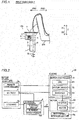
- the marine propulsion unit 100 includes an electric thruster that propels a marine vessel body 200.
- the marine propulsion unit 100 includes a tubular duct 1, a propeller 2, a steering shaft 3, a casing 4, a motor controller 5, and a steering mechanism 6.
- the duct 1 includes a stator 11.
- the propeller 2 includes a rim 21 and blades 22.
- the rim 21 includes a rotor 23.
- a motor 10 (switched reluctance motor) includes the stator 11 and the rotor 23.
- the marine propulsion unit 100 is mounted on the marine vessel body 200 via a bracket 7.
- the marine vessel body 200 includes a battery 8, a remote controller 9a, and a steering wheel 9b.
- the marine propulsion unit 100 (motor 10) is connected to the motor controller 5.
- the battery 8 and the remote controller 9a are further connected to the motor controller 5.
- the motor controller 5 includes a CPU (central processing unit) 51, a motor driver 52, and an inverter 53.
- the marine propulsion unit 100 (duct 1) is rotatable about a steering axis B that intersects with the rotation axis A of the propeller 2.
- the marine propulsion unit 100 is steered (rotated) by the steering mechanism 6.
- the steering mechanism 6 includes an electric motor 61 and a steering angle sensor 62.
- the steering mechanism 6 steers the duct 1 and the casing 4 by rotating the steering shaft 3.
- the steering mechanism 6 is connected to the battery 8 and the steering wheel 9b.
- the remote controller 9a is operated such that the magnitude of the propulsive force of the marine propulsion unit 100 is adjusted.
- the steering wheel 9b is operated such that the direction (the orientation of the duct 1) of the propulsive force of the marine propulsion unit 100 is adjusted. In other words, the steering wheel 9b is manipulated such that the orientation of the marine propulsion unit 100 is changed, and the marine vessel body 200 is steered.
- the duct 1 is tubular.
- the sectional shape of the duct 1 varies along the rotation axis A of the propeller 2.
- a portion of the duct 1 in a direction X1 expands outward, and a portion of the duct 1 in a direction X2 gradually narrows.
- a circumferential recess recessed radially outward from the inner surface thereof is provided in the duct 1.
- the propeller 2 is accommodated in the recess. Specifically, the propeller 2 is rotatably supported by the duct 1 via a fluid bearing provided along the recess of the duct 1.
- the stator 11 is disposed on the outer periphery of the recess of the duct 1.
- the stator 11 includes windings. In the stator 11, electric power is supplied to the windings such that a magnetic field is generated. A plurality of windings are disposed circumferentially along the recess of the tubular duct 1. Electric power is supplied to the plurality of windings in synchronization with the number of rotations. Thus, the magnetic force of the stator 11 acts on the rotor 23 of the propeller 2, and the propeller 2 is rotated.
- the propeller 2 is rotatably disposed radially inward of the tubular duct 1.
- the rim 21 of the propeller 2 is provided in a tubular shape outside the blades 22.
- the blades 22 are provided radially inward of the rim 21 from the inner surface of the rim 21. As shown in Fig. 3 , four blades 22 are provided at equal intervals (every 90 degrees) in the circumferential direction.
- the blades 22 are wing-shaped.
- the rotor 23 is provided outside the rim 21.
- the rotor 23 is disposed at a position that faces the stator 11 of the duct 1. Specifically, the rotor 23 and the stator 11 face each other at a predetermined interval in a radial direction. That is, the motor 10 including the stator 11 and the rotor 23 is a radial gap motor.
- a portion having a high magnetic permeability and a portion having a low magnetic permeability are alternately and circumferentially disposed. That is, a reluctance torque is generated in the rotor 23 due to the magnetic force generated from the stator 11.
- the rotor 23 (rim 21) rotates.
- the steering shaft 3 supports the duct 1 such that the duct 1 is steerable.
- the steering shaft 3 is rotatably supported by the steering mechanism 6 via a tapered roller bearing 31.
- the steering shaft 3 supports the casing 4 integral and unitary with the duct 1 via a cylindrical roller bearing 32.
- the steering shaft 3 is hollow. In the interior of the hollow steering shaft 3, wiring through which electric power is supplied to the stator 11, wiring that connects the motor controller 5 to the battery 8, wiring that connects the remote controller 9a to the motor controller 5, and wiring that connects the steering wheel 9b to the steering mechanism 6 are housed.
- the steering shaft 3 includes seals 33 and 34, and water intrusion into the casing 4, the steering mechanism 6, and the stator 11 is prevented.
- the seal 33 is provided between the steering shaft 3 and the steering mechanism 6.
- the seal 34 is provided between the steering shaft 3 and the casing 4.
- the casing 4 is provided separately from the steering shaft 3, and extends along the rotation axis A of the propeller 2.
- the motor controller 5 is disposed in the casing 4.
- the casing 4 is fixed to the duct 1 so as to be steerable together with the duct 1.
- the casing 4 is integral and unitary with the duct 1.
- the casing 4 is disposed above the duct 1. Specifically, the casing 4 is disposed between the duct 1 and the steering mechanism 6. At least a portion of the casing 4 is located rearward of the steering shaft 3. At least a portion of the casing 4 extends rearward of the rear end of the duct 1. Specifically, in a planar view, the length of the casing 4 in a direction parallel to the rotation axis A of the propeller 2 is larger than the length of the casing 4 in a direction perpendicular to the rotation axis A of the propeller 2. That is, the casing 4 extends along a plane parallel to the rotation axis A of the propeller 2 and parallel to an upward-downward direction.
- the casing 4 functions as a skeg. In other words, the casing 4 also acts as a fin that stabilizes the traveling performance of the marine vessel body 200.
- the casing 4 is streamlined along the rotation axis A of the propeller 2. Specifically, the casing 4 is streamlined such that the resistance to water that flows relatively in a direction X is small.
- the casing 4 includes a heat radiator 41 and a lid 42.
- the heat radiator 41 is disposed near a region of the casing 4 in which the motor controller 5 is disposed while being exposed to the outside.
- the heat radiator 41 radiates the heat of the motor controller 5 to the outside.
- the heat radiator 41 is made of a metal material such as aluminum.
- On the outer surface of the heat radiator 41 a plurality of fins that extend in the direction X are provided. Thus, the surface area can be increased, and thus it is possible to efficiently radiate the heat.
- the heat radiator 41 is provided on one side of the casing 4 in a right-left direction.
- the lid 42 is provided on the other side of the casing 4 in the right-left direction.
- the lid 42 is provided to take the motor controller 5 in and out of the casing 4.
- the lid 42 covers the motor controller 5.
- the heat radiator 41 and the lid 42 are mounted on the casing 4 via a seal. That is, the casing 4 is hermetically sealed in a state where the heat radiator 41 and the lid 42 are mounted.
- the motor controller 5 controls the rotational driving of the propeller 2 (motor 10). Specifically, the motor controller 5 controls the rotational speed of the motor 10 based on the operation of the remote controller 9a.
- the CPU 51 receives a signal from a rotational speed detector 10a provided in the motor 10. The CPU 51 supplies electric power to the motor 10 (stator 11) via the motor driver 52 and the inverter 53.
- the motor controller 5 (the CPU 51, the motor driver 52, and the inverter 53) is provided on a substrate 5a.
- the substrate 5a is flat plate-shaped.
- the substrate 5a extends substantially parallel to the rotation axis A of the propeller 2.
- the substrate 5a is disposed in the casing 4 elongated so as to extend in a direction in which the substrate 5a extends.
- the substrate 5a is disposed in contact with the heat radiator 41.
- the steering mechanism 6 is disposed above the duct 1, and steers the duct 1.
- the electric motor 61 of the steering mechanism 6 is driven based on the operation of the steering wheel 9b (see Fig. 2 ). Electric power is supplied from the battery 8 to the electric motor 61 via a driver, and the electric motor 61 is rotationally driven.
- the electric motor 61 rotates the steering shaft 3 via a worm gear 61a and a gear 3a.
- a speed reducer 61b is provided between the electric motor 61 and the worm gear 61a.
- the speed reducer 61b includes a planetary gear.
- the steering angle sensor 62 detects the rotation angle of the steering shaft 3. The detected rotation angle of the steering shaft 3 is feedback-controlled, and the electric motor 61 is driven.
- the outer surface of the steering mechanism 6 is streamlined in a forward-backward movement direction. As shown in Figs. 1 and 6 , the upper surface (the surface in a direction Z1) of the steering mechanism 6 is fixed to the bracket 7 mounted on the marine vessel body 200.
- the bracket 7 supports the marine propulsion unit 100, and is mounted on the rear of the marine vessel body 200.
- the bracket 7 includes a marine vessel body mount 71 and a propulsion unit mount 72.
- the marine vessel body mount 71 is flat plate-shaped.
- the marine vessel body mount 71 is mounted on a transom on the rear of the marine vessel body 200.
- the propulsion unit mount 72 is mounted on the marine vessel body mount 71 at a predetermined angle.
- the propulsion unit mount 72 is flat plate-shaped in a substantially horizontal direction.
- the marine propulsion unit 100 is mounted on the propulsion unit mount 72.
- a plurality of marine propulsion units 100 can be mounted on the propulsion unit mount 72.
- the propulsion unit mount 72 includes a plurality of holes 711 (insertion holes for bolts) used to mount the marine propulsion unit 100.
- the marine vessel body mount 71 includes a plurality of holes 711 corresponding to a bracket used to mount an outboard motor including an engine.
- the holes 711 of the marine vessel body mount 71 are disposed in rows at an interval of about 12.8 inches (about 327 mm) in the right-left direction, similarly to the bracket of the outboard motor, for example.
- the motor controller 5 that controls the rotational driving of the propeller 2 is disposed in the casing 4 provided separately from the steering shaft 3 and that extends along the rotation axis A of the propeller 2. Accordingly, the motor controller 5 and the motor 10 can be disposed close to each other, and thus it is possible to significantly reduce or prevent an increase in the length of wiring that connects the motor controller 5 to the motor 10. Consequently, it is possible to significantly reduce or prevent complexity of the wiring.
- the size of the casing 4 is increased along the rotation axis A of the propeller 2 such that the motor controller 5 can be housed in the casing 4, and thus it is possible to significantly reduce or prevent an excessive increase in the size of the marine propulsion unit 100 unlike the case where the diameter of the steering shaft 3 is increased.
- the casing 4 extends along the rotation axis A of the propeller 2 such that it is possible to significantly reduce or prevent an increase in water resistance, and thus even when the casing 4 is provided, the marine vessel can be propelled without problems.
- the casing 4 can be disposed in the water, and thus it is possible to efficiently cool the motor controller 5 disposed in the casing 4.
- the casing 4 is fixed to the duct 1 so as to be steerable together with the duct 1. Accordingly, the duct 1 and the casing 4 are integrally steered, and thus even when the duct 1 is steered, it is possible to significantly reduce or prevent an increase in water resistance due to the casing 4.
- the casing 4 is integral and unitary with the duct 1. Accordingly, as compared with the case where the duct 1 and the casing 4 are provided separately from each other, it is possible to reduce the number of components and to eliminate a bonded surface between the duct 1 and the casing 4, and thus it is possible to effectively significantly reduce or prevent water intrusion.
- the casing 4 is disposed above the duct 1. Accordingly, when the duct 1 is located at a distance below the water surface in order to significantly reduce or prevent entrainment of air from the water surface, the casing 4 can be disposed by effectively utilizing a space between the duct 1 and the water surface.
- the casing 4 is located rearward of the steering shaft 3. Accordingly, the casing 4 can extend rearward of the steering shaft 3, and thus when the casing 4 is steered together with the duct 1, it is possible to significantly reduce or prevent interference of the casing 4 with the marine vessel body 200 on which the marine propulsion unit 100 is mounted.
- the casing 4 extends rearward of the rear end of the duct 1. Accordingly, even when the size of the motor controller 5 is increased, the casing 4 extends rearward of the rear end of the duct 1 such that the size of the casing 4 can be increased, and thus the motor controller 5 can be easily housed in the casing 4.
- the casing 4 functions as a skeg. Accordingly, it is possible to improve the steering performance of the marine vessel using the casing 4 in which the motor controller 5 is disposed.
- the length of the casing 4 in the direction parallel to the rotation axis A of the propeller 2 is larger than the length of the casing 4 in the direction perpendicular to the rotation axis A of the propeller 2. Accordingly, it is possible to significantly reduce or prevent an increase in the projected area when the casing 4 is viewed along the rotation axis A of the propeller 2, and thus it is possible to effectively significantly reduce or prevent an increase in water resistance.
- the heat radiator 41 exposed to the outside is provided near the region of the casing 4 in which the motor controller 5 is disposed. Accordingly, the heat of the motor controller 5 can be easily discharged to the outside (into the water) via the heat radiator 41, and thus the motor controller 5 can be effectively cooled.
- the motor controller 5 is provided on the substrate 5a that extends substantially parallel to the rotation axis A of the propeller 2, and the casing 4 is elongated so as to extend in the direction in which the substrate 5a extends. Accordingly, the substrate 5a on which the motor controller 5 is provided can be easily housed in the elongated casing 4.
- the casing 4 is streamlined along the rotation axis A of the propeller 2. Accordingly, the water resistance in the casing 4 can be effectively reduced, and thus even when the casing 4 is provided, the marine vessel can be efficiently propelled.
- the motor controller 5 includes the motor driver 52 and the inverter 53. Accordingly, the motor driver 52 and the inverter 53 can be housed in the casing 4 located in the water, and thus the motor driver 52 and the inverter 53 can be effectively cooled.
- the sectional shape of the duct 1 varies along the rotation axis A of the propeller 2. Accordingly, a fluid that flows through the duct 1 can be rectified, and thus a propulsive force can be efficiently generated.
- At least three and not more than eight blades 22 are provided. Accordingly, the at least three and not more than eight blades 22 can be disposed in a balanced manner radially inward of the rim 21, and thus the marine propulsion unit 100 can be efficiently operated.
- the steering mechanism 6 disposed above the duct 1 and that steers the duct 1 is provided, and the casing 4 is disposed between the duct 1 and the steering mechanism 6. Accordingly, the duct 1 can be easily steered by the steering mechanism 6.
- the casing 4 can be disposed by effectively utilizing a space between the duct 1 and the steering mechanism 6.
- the steering mechanism 6 is streamlined in the forward-backward movement direction. Accordingly, the water resistance in the steering mechanism 6 can be effectively reduced, and thus the marine vessel can be more efficiently propelled.
- the steering mechanism 6 rotates the steering shaft 3 by driving the electric motor 61. Accordingly, the electric motor 61 is driven such that the duct 1 can be easily steered.
- the upper surface of the steering mechanism 6 is fixed to the bracket 7 mounted on the marine vessel body 200. Accordingly, the steering mechanism 6 can be reliably mounted on the marine vessel body 200.
- the bracket 7 includes the marine vessel body mount 71 and the propulsion unit mount 72. Accordingly, it is possible to fix the marine vessel body mount 71 to the marine vessel body 200 and to fix the marine propulsion unit 100 to the propulsion unit mount 72, and thus the marine propulsion unit 100 can be reliably mounted on the marine vessel body 200.
- FIG. 9 A second embodiment of the present invention is now described with reference to Fig. 9 .
- a casing is disposed behind a duct
- the same structures as those of the first embodiment are denoted by the same reference numerals.
- a marine propulsion unit 300 includes a tubular duct 1, a propeller 2, a steering shaft 3, a casing 4a, a motor controller 5, and a steering mechanism 6.
- the casing 4a is provided separately from the steering shaft 3, and extends along the rotation axis A of the propeller 2.
- the motor controller 5 is disposed in the casing 4a. At least a portion of the casing 4a extends rearward of the rear end of the duct 1.
- the casing 4a is fixed to the duct 1 behind the duct 1 on the rotation axis A of the propeller 2. Specifically, the casing 4a extends in an upward-downward direction (direction Z) behind the duct 1.
- the motor controller 5 that controls the rotational driving of the propeller 2 is disposed in the casing 4a provided separately from the steering shaft 3 and that extends along the rotation axis A of the propeller 2. Accordingly, it is possible to significantly reduce or prevent an increase in the size of the marine propulsion unit while significantly reducing or preventing complexity of wiring.
- the casing 4a is fixed to the duct 1 behind the duct 1 on the rotation axis A of the propeller 2. Accordingly, water flow discharged from the duct 1 can be rectified by the casing 4a, and thus a marine vessel can be more efficiently propelled.
- FIG. 10 A third embodiment of the present invention is now described with reference to Figs. 10 to 13 .
- this third embodiment an example in which a collar is provided at a duct connection that surrounds a steering shaft is described.
- the same structures as those of the first embodiment are denoted by the same reference numerals.
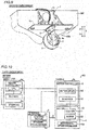
- a marine propulsion unit 400 includes a tubular duct 1, a propeller 2 (see Fig. 11 ), a steering shaft 3, a casing 4b, a motor controller 5, and a steering mechanism 6.
- a remote controller 9a provided on a marine vessel body 200 includes a CPU 91.
- the CPU 91 is connected to the motor controller 5.
- the CPU 91 controls the rotational driving of the propeller 2 (motor 10) via the motor controller 5.
- the CPU 91 controls the rotational speed of the motor 10 based on the operation of the remote controller 9a.
- the CPU 91 receives a signal from a rotational speed detector 10a provided in the motor 10.
- the CPU 91 supplies electric power to the motor 10 (stator 11) via the motor controller 5 (a motor driver 52 and an inverter 53).
- the CPU 91 controls the steering mechanism 6 based on the operation of a steering wheel 9b.
- the CPU 91 supplies electric power to the steering mechanism 6 via the motor controller 5. That is, the CPU 91 controls the steering mechanism 6 to steer the duct 1 via the motor controller 5 based on the operation of the steering wheel 9b.
- the CPU 91 provided in the marine vessel body 200 can concentrate control of the marine vessel maneuvering operation.
- the casing 4b is provided separately from the steering shaft 3, and extends along the rotation axis A (see Fig. 1 ) of the propeller 2.
- the motor controller 5 is disposed in the casing 4b.
- the casing 4b is fixed to the duct 1 so as to be steerable together with the duct 1.
- the casing 4b is connected above the duct 1, and is mounted on a duct connection 43 that surrounds the steering shaft 3. More specifically, the casing 4b is attachable to and detachable from the rear of the duct connection 43.
- the duct 1 is dividable into a central portion 12, a front portion 13, and a rear portion 14.
- the stator 11 (see Fig. 10 ) is disposed in the central portion 12.
- the central portion 12 is connected to a lower portion of the duct connection 43.
- the central portion 12 and the duct connection 43 are integral and unitary with each other.
- the propeller 2 is mounted on the central portion 12 in a state where the central portion 12, the front portion 13, and the rear portion 14 are separate from each other.
- the front portion 13 is connected to a front portion of the central portion 12. Screws provided on the inner periphery of the central portion 12 and screws provided on the outer periphery of the front portion 13 engage with each other such that the front portion 13 is fixed to the central portion 12.
- the rear portion 14 is connected to a rear portion of the central portion 12. Screws provided on the inner periphery of the central portion 12 and screws provided on the outer periphery of the rear portion 14 engage with each other such that the rear portion 14 is fixed to the central portion 12.
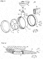
- the duct connection 43 is connected to an upper portion of the duct 1, as shown in Fig. 11 .
- the duct connection 43 surrounds the steering shaft 3.
- the duct connection 43 includes a housing 431, a collar 432, and through-holes 433.
- the housing 431 includes an internal space 43a.
- the steering shaft 3 is disposed in the internal space 43a of the housing 431. Specifically, in the internal space 43a of the housing 431, a lower portion of a housing of the steering mechanism 6 and the steering shaft 3 disposed inside the housing of the steering mechanism 6 are disposed.
- the collar 432 is disposed in the internal space 43a between the housing 431 and the steering shaft 3 at the upper end of the housing 431.
- the collar 432 is provided to reduce an opening area that communicates with the internal space 43a of the duct connection 43.
- the collar 432 is disposed between the housing 431 and the housing of the steering mechanism 6.
- the collar 432 is annular.
- the collar 432 is made of a resin.
- the collar 432 is press-fitted such that its outer peripheral portion contacts the housing 431.
- the radial length d2 of a gap of the inner periphery or the outer periphery of the collar 432 is smaller than the inner diameter d1 of each of the through-holes 433.
- the through-holes 433 communicate between the internal space 43a in which the steering shaft 3 is disposed and the outside.
- the through-holes 433 are provided below (in a direction Z2) the collar 432.
- a total of two through-holes 433 are provided, one of which is located on the left side of the duct connection 43 and the other of which is located on the right side of the duct connection 43.
- the through-holes 433 are provided in the vicinity of the lower end of the internal space 43a of the housing 431.
- the motor controller 5 that controls the rotational driving of the propeller 2 is disposed in the casing 4b provided separately from the steering shaft 3 and that extends along the rotation axis A of the propeller 2. Accordingly, it is possible to significantly reduce or prevent an increase in the size of the marine propulsion unit while significantly reducing or preventing complexity of wiring.
- the duct connection 43 includes the housing 431 including the internal space 43a in which the steering shaft 3 is disposed, the collar 432 disposed in the internal space 43a between the housing 431 and the steering shaft 3 at the upper end of the housing 431, and the through-holes 433 provided below the collar 432 and that communicate between the internal space 43a in which the steering shaft 3 is disposed and the outside. Accordingly, the collar 432 can significantly reduce or prevent entry of foreign matter into the duct connection 43 from the upper surface. Even when foreign matter enters the duct connection 43, the foreign matter can be discharged from the through-holes 433 provided below. Thus, it is possible to significantly reduce or prevent accumulation of foreign matter in the duct connection 43.
- the radial length d2 of the gap of the inner periphery or the outer periphery of the collar 432 is smaller than the inner diameter d1 of each of the through-holes 433. Accordingly, even when foreign matter enters from the gap of the inner periphery or the outer periphery of the collar 432, the foreign matter can be easily discharged from the through-holes 433 each having an inner diameter larger than that of the gap.
- a plurality of marine propulsion units may be provided on the marine vessel body.
- two marine propulsion units 100 may be provided on a marine vessel body 200.
- the casing may be elongated so as to extend in a right-left direction and the forward-backward direction (horizontal direction).
- the casing may function as a cavitation plate that significantly reduces or prevents entrainment of air during the driving of the propeller.
- the motor controller includes the CPU, the motor driver, and the inverter has been shown in each of the first and second embodiments described above, the present invention is not restricted to this. According to the present invention, the motor controller may include at least one of the motor driver and the inverter.
- a tiller handle or the like may be provided to manually steer the duct (marine propulsion unit).
- the steering mechanism is electrically driven.
- the steering mechanism may be hydraulically driven.
- the marine propulsion unit is manipulated based on the operation of the steering wheel and the remote controller
- the present invention is not restricted to this.
- the marine propulsion unit may be manipulated based on the operation of a joystick, for example.
- the present invention is not restricted to this. According to the present invention, the number of the blades may be three or less, or five or more.
- a shaft connected to the blades may be provided on the rotation axis of the propeller.
- the motor including the stator and the rotor is a radial gap motor
- the present invention is not restricted to this.
- the motor may be an axial gap motor in which a stator and a rotor face each other along its rotation axis.
- the motor including the stator and the rotor is a reluctance torque motor
- the present invention is not restricted to this.
- the motor may be a permanent magnet motor in which a plurality of permanent magnets are provided in a rotor.
- the marine propulsion unit according to the present invention may be mounted on the front or side of the marine vessel body. Description of Reference Numerals
Landscapes
- Chemical & Material Sciences (AREA)
- Engineering & Computer Science (AREA)
- Combustion & Propulsion (AREA)
- Mechanical Engineering (AREA)
- Ocean & Marine Engineering (AREA)
- Motor Or Generator Frames (AREA)
- Power Steering Mechanism (AREA)
Priority Applications (1)
| Application Number | Priority Date | Filing Date | Title |
|---|---|---|---|
| EP20160973.2A EP3705393B1 (de) | 2015-11-11 | 2016-11-08 | Schiffsantriebseinheit |
Applications Claiming Priority (2)
| Application Number | Priority Date | Filing Date | Title |
|---|---|---|---|
| JP2015221550 | 2015-11-11 | ||
| PCT/JP2016/083102 WO2017082248A1 (ja) | 2015-11-11 | 2016-11-08 | 船舶推進装置 |
Related Child Applications (2)
| Application Number | Title | Priority Date | Filing Date |
|---|---|---|---|
| EP20160973.2A Division EP3705393B1 (de) | 2015-11-11 | 2016-11-08 | Schiffsantriebseinheit |
| EP20160973.2A Division-Into EP3705393B1 (de) | 2015-11-11 | 2016-11-08 | Schiffsantriebseinheit |
Publications (3)
| Publication Number | Publication Date |
|---|---|
| EP3375705A1 true EP3375705A1 (de) | 2018-09-19 |
| EP3375705A4 EP3375705A4 (de) | 2018-10-24 |
| EP3375705B1 EP3375705B1 (de) | 2020-04-15 |
Family
ID=58695391
Family Applications (2)
| Application Number | Title | Priority Date | Filing Date |
|---|---|---|---|
| EP20160973.2A Active EP3705393B1 (de) | 2015-11-11 | 2016-11-08 | Schiffsantriebseinheit |
| EP16864209.8A Active EP3375705B1 (de) | 2015-11-11 | 2016-11-08 | Schiffsantriebsvorrichtung |
Family Applications Before (1)
| Application Number | Title | Priority Date | Filing Date |
|---|---|---|---|
| EP20160973.2A Active EP3705393B1 (de) | 2015-11-11 | 2016-11-08 | Schiffsantriebseinheit |
Country Status (4)
| Country | Link |
|---|---|
| US (1) | US10618617B2 (de) |
| EP (2) | EP3705393B1 (de) |
| JP (1) | JP6783243B2 (de) |
| WO (1) | WO2017082248A1 (de) |
Cited By (3)
| Publication number | Priority date | Publication date | Assignee | Title |
|---|---|---|---|---|
| CN113815832A (zh) * | 2021-09-19 | 2021-12-21 | 苏州汉瑞船舶推进系统有限公司 | 轮缘驱动的半浸式推进器 |
| WO2022045986A1 (en) * | 2020-08-28 | 2022-03-03 | Remigo, Proizvodnja In Trgovina, D.O.O. | Integrated electric outboard motor |
| EP4306404A1 (de) * | 2022-07-14 | 2024-01-17 | Yanmar Holdings Co., Ltd. | Elektromotorischer segelantrieb und schiff |
Families Citing this family (22)
| Publication number | Priority date | Publication date | Assignee | Title |
|---|---|---|---|---|
| AU2017268537B1 (en) * | 2017-11-28 | 2018-07-26 | Fliteboard Pty Ltd | Module for Connecting a Mast to a Board |
| CN110395377A (zh) * | 2019-08-02 | 2019-11-01 | 武汉札古海洋科技有限公司 | 一种水下推进器 |
| JP2021104715A (ja) | 2019-12-26 | 2021-07-26 | ヤマハ発動機株式会社 | 船舶推進装置および船舶 |
| JP2021104714A (ja) | 2019-12-26 | 2021-07-26 | ヤマハ発動機株式会社 | 船舶推進装置および船舶 |
| CN110963014A (zh) * | 2019-12-30 | 2020-04-07 | 宁波海伯集团有限公司 | 一种小型船用推进器 |
| JP2022018647A (ja) * | 2020-07-16 | 2022-01-27 | ヤマハ発動機株式会社 | 船外機 |
| JP7132296B2 (ja) | 2020-09-15 | 2022-09-06 | ヤマハ発動機株式会社 | 操船システムおよび船舶 |
| WO2023034027A1 (en) * | 2021-09-05 | 2023-03-09 | Muller Peter Jacques | Rim driven thruster with adjustable rotor blade pitch |
| JP7753745B2 (ja) * | 2021-09-17 | 2025-10-15 | スズキ株式会社 | ハイブリッド船舶推進機 |
| CN113650771A (zh) * | 2021-09-18 | 2021-11-16 | 国网智慧能源交通技术创新中心(苏州)有限公司 | 一种基于集成转舵系统的轮缘推进系统 |
| CN114455053B (zh) * | 2022-01-22 | 2023-03-07 | 嘉兴市锦佳船舶制造股份有限公司 | 一种河湖巡查船 |
| US12065230B1 (en) | 2022-02-15 | 2024-08-20 | Brunswick Corporation | Marine propulsion control system and method with rear and lateral marine drives |
| US12304330B1 (en) | 2022-02-16 | 2025-05-20 | Charles B. Hickcox, III | Electric outboard motor |
| WO2023187887A1 (ja) * | 2022-03-28 | 2023-10-05 | 本田技研工業株式会社 | 電動船外機および船舶 |
| CN115092374B (zh) * | 2022-06-28 | 2024-01-19 | 北京航空航天大学 | 一种泵喷式水下矢量推进器 |
| US12134454B1 (en) | 2022-07-20 | 2024-11-05 | Brunswick Corporation | Marine propulsion system and method with single rear drive and lateral marine drive |
| US12258115B2 (en) | 2022-07-20 | 2025-03-25 | Brunswick Corporation | Marine propulsion system and joystick control method |
| US12110088B1 (en) | 2022-07-20 | 2024-10-08 | Brunswick Corporation | Marine propulsion system and method with rear and lateral marine drives |
| CN115195981B (zh) | 2022-07-21 | 2024-08-30 | 江苏科技大学 | 一种无滑环电力吊舱推进装置及其装配方法 |
| JP2024082913A (ja) * | 2022-12-09 | 2024-06-20 | ヤマハ発動機株式会社 | 船舶推進機および船舶 |
| CN116729607A (zh) * | 2023-05-31 | 2023-09-12 | 大连海事大学 | 一种桨舵一体的吊舱对转轮缘推进器 |
| JP2025141491A (ja) * | 2024-03-15 | 2025-09-29 | 本田技研工業株式会社 | 水上移動体用推進装置 |
Family Cites Families (7)
| Publication number | Priority date | Publication date | Assignee | Title |
|---|---|---|---|---|
| US5306183A (en) * | 1993-02-25 | 1994-04-26 | Harbor Branch Oceanographic Institute Inc. | Propulsion systems for submarine vessels |
| JP3672122B2 (ja) * | 1995-12-14 | 2005-07-13 | 株式会社モリック | 電動船外機の制御装置 |
| US6692319B2 (en) * | 2002-03-29 | 2004-02-17 | Alstom Shilling Robotics | Thruster for submarine vessels |
| JP2006056458A (ja) * | 2004-08-23 | 2006-03-02 | Yamaha Marine Co Ltd | 電動推進機 |
| JP5872255B2 (ja) * | 2011-11-08 | 2016-03-01 | ヤマハ発動機株式会社 | 船舶推進装置 |
| JP5844617B2 (ja) * | 2011-11-08 | 2016-01-20 | ヤマハ発動機株式会社 | 船舶推進装置 |
| ITTO20130045A1 (it) * | 2013-01-18 | 2014-07-19 | P Gevs Srl | Sistema di propulsione fuoribordo per natanti |
-
2016
- 2016-11-08 WO PCT/JP2016/083102 patent/WO2017082248A1/ja not_active Ceased
- 2016-11-08 EP EP20160973.2A patent/EP3705393B1/de active Active
- 2016-11-08 JP JP2017550333A patent/JP6783243B2/ja active Active
- 2016-11-08 EP EP16864209.8A patent/EP3375705B1/de active Active
-
2018
- 2018-05-10 US US15/975,812 patent/US10618617B2/en active Active
Cited By (3)
| Publication number | Priority date | Publication date | Assignee | Title |
|---|---|---|---|---|
| WO2022045986A1 (en) * | 2020-08-28 | 2022-03-03 | Remigo, Proizvodnja In Trgovina, D.O.O. | Integrated electric outboard motor |
| CN113815832A (zh) * | 2021-09-19 | 2021-12-21 | 苏州汉瑞船舶推进系统有限公司 | 轮缘驱动的半浸式推进器 |
| EP4306404A1 (de) * | 2022-07-14 | 2024-01-17 | Yanmar Holdings Co., Ltd. | Elektromotorischer segelantrieb und schiff |
Also Published As
| Publication number | Publication date |
|---|---|
| JP6783243B2 (ja) | 2020-11-11 |
| WO2017082248A1 (ja) | 2017-05-18 |
| JPWO2017082248A1 (ja) | 2018-08-30 |
| US10618617B2 (en) | 2020-04-14 |
| EP3705393B1 (de) | 2022-04-27 |
| EP3375705B1 (de) | 2020-04-15 |
| EP3375705A4 (de) | 2018-10-24 |
| US20180257750A1 (en) | 2018-09-13 |
| EP3705393A1 (de) | 2020-09-09 |
Similar Documents
| Publication | Publication Date | Title |
|---|---|---|
| EP3375705B1 (de) | Schiffsantriebsvorrichtung | |
| EP3000718B1 (de) | Elektroantriebsvorrichtung | |
| US12234001B2 (en) | Outboard motor | |
| JP2018079743A (ja) | 船舶用推進装置およびそれを備えた船舶 | |
| JP2004306947A (ja) | 船体推進ユニット | |
| JP2003011889A (ja) | アジマス推進器 | |
| US10661868B2 (en) | Vessel propulsion apparatus and vessel including the same | |
| FI121659B (fi) | Vesialuksen propulsiojärjestelmä | |
| US6638122B1 (en) | Electric marine propulsion employing switched reluctance motor drive | |
| JP7734036B2 (ja) | 人力駆動車用のコンポーネント | |
| JP2004142700A (ja) | 船舶におけるポッド型推進器 | |
| JP4005601B2 (ja) | 推進システムの配置 | |
| KR101422239B1 (ko) | 선박 추진장치 | |
| US9981729B2 (en) | Outboard motor | |
| EP3939878B1 (de) | Aussenbordmotor | |
| CN214267930U (zh) | 推进器和水上运行装置 | |
| CN214267931U (zh) | 推进器和水上运行设备 | |
| JP2024090360A (ja) | 船外機 | |
| KR101335256B1 (ko) | 터널식 스러스터 및 이를 갖춘 선박 | |
| US12497150B1 (en) | Trolling motor steering unite | |
| US10106236B2 (en) | Outboard motor | |
| WO2005058690A1 (en) | Support for propulsion apparatus for a water-borne vessel, and propulsion apparatus incorporating such support | |
| KR20150002615U (ko) | 고정식 러더벌브를 구비한 전가동타 | |
| US12139244B2 (en) | Marine vessel and marine propulsion unit | |
| JP3056279B2 (ja) | 船舶推進機におけるロワーケーシングとロワーケーシングキャップとの固定構造 |
Legal Events
| Date | Code | Title | Description |
|---|---|---|---|
| STAA | Information on the status of an ep patent application or granted ep patent |
Free format text: STATUS: THE INTERNATIONAL PUBLICATION HAS BEEN MADE |
|
| PUAI | Public reference made under article 153(3) epc to a published international application that has entered the european phase |
Free format text: ORIGINAL CODE: 0009012 |
|
| STAA | Information on the status of an ep patent application or granted ep patent |
Free format text: STATUS: REQUEST FOR EXAMINATION WAS MADE |
|
| 17P | Request for examination filed |
Effective date: 20180524 |
|
| AK | Designated contracting states |
Kind code of ref document: A1 Designated state(s): AL AT BE BG CH CY CZ DE DK EE ES FI FR GB GR HR HU IE IS IT LI LT LU LV MC MK MT NL NO PL PT RO RS SE SI SK SM TR |
|
| AX | Request for extension of the european patent |
Extension state: BA ME |
|
| A4 | Supplementary search report drawn up and despatched |
Effective date: 20180924 |
|
| RIC1 | Information provided on ipc code assigned before grant |
Ipc: B63H 20/06 20060101ALI20180918BHEP Ipc: B63H 25/42 20060101ALI20180918BHEP Ipc: B63H 20/02 20060101ALI20180918BHEP Ipc: B63H 25/26 20060101ALI20180918BHEP Ipc: B63H 5/07 20060101ALI20180918BHEP Ipc: B63H 20/00 20060101AFI20180918BHEP Ipc: B63H 1/12 20060101ALI20180918BHEP |
|
| DAV | Request for validation of the european patent (deleted) | ||
| DAX | Request for extension of the european patent (deleted) | ||
| STAA | Information on the status of an ep patent application or granted ep patent |
Free format text: STATUS: EXAMINATION IS IN PROGRESS |
|
| 17Q | First examination report despatched |
Effective date: 20190712 |
|
| GRAP | Despatch of communication of intention to grant a patent |
Free format text: ORIGINAL CODE: EPIDOSNIGR1 |
|
| STAA | Information on the status of an ep patent application or granted ep patent |
Free format text: STATUS: GRANT OF PATENT IS INTENDED |
|
| INTG | Intention to grant announced |
Effective date: 20191114 |
|
| GRAS | Grant fee paid |
Free format text: ORIGINAL CODE: EPIDOSNIGR3 |
|
| GRAA | (expected) grant |
Free format text: ORIGINAL CODE: 0009210 |
|
| STAA | Information on the status of an ep patent application or granted ep patent |
Free format text: STATUS: THE PATENT HAS BEEN GRANTED |
|
| AK | Designated contracting states |
Kind code of ref document: B1 Designated state(s): AL AT BE BG CH CY CZ DE DK EE ES FI FR GB GR HR HU IE IS IT LI LT LU LV MC MK MT NL NO PL PT RO RS SE SI SK SM TR |
|
| REG | Reference to a national code |
Ref country code: CH Ref legal event code: EP |
|
| REG | Reference to a national code |
Ref country code: DE Ref legal event code: R096 Ref document number: 602016034278 Country of ref document: DE |
|
| REG | Reference to a national code |
Ref country code: IE Ref legal event code: FG4D |
|
| REG | Reference to a national code |
Ref country code: AT Ref legal event code: REF Ref document number: 1256977 Country of ref document: AT Kind code of ref document: T Effective date: 20200515 |
|
| REG | Reference to a national code |
Ref country code: NL Ref legal event code: FP |
|
| REG | Reference to a national code |
Ref country code: LT Ref legal event code: MG4D |
|
| PG25 | Lapsed in a contracting state [announced via postgrant information from national office to epo] |
Ref country code: SE Free format text: LAPSE BECAUSE OF FAILURE TO SUBMIT A TRANSLATION OF THE DESCRIPTION OR TO PAY THE FEE WITHIN THE PRESCRIBED TIME-LIMIT Effective date: 20200415 Ref country code: FI Free format text: LAPSE BECAUSE OF FAILURE TO SUBMIT A TRANSLATION OF THE DESCRIPTION OR TO PAY THE FEE WITHIN THE PRESCRIBED TIME-LIMIT Effective date: 20200415 Ref country code: IS Free format text: LAPSE BECAUSE OF FAILURE TO SUBMIT A TRANSLATION OF THE DESCRIPTION OR TO PAY THE FEE WITHIN THE PRESCRIBED TIME-LIMIT Effective date: 20200815 Ref country code: GR Free format text: LAPSE BECAUSE OF FAILURE TO SUBMIT A TRANSLATION OF THE DESCRIPTION OR TO PAY THE FEE WITHIN THE PRESCRIBED TIME-LIMIT Effective date: 20200716 Ref country code: NO Free format text: LAPSE BECAUSE OF FAILURE TO SUBMIT A TRANSLATION OF THE DESCRIPTION OR TO PAY THE FEE WITHIN THE PRESCRIBED TIME-LIMIT Effective date: 20200715 Ref country code: LT Free format text: LAPSE BECAUSE OF FAILURE TO SUBMIT A TRANSLATION OF THE DESCRIPTION OR TO PAY THE FEE WITHIN THE PRESCRIBED TIME-LIMIT Effective date: 20200415 Ref country code: PT Free format text: LAPSE BECAUSE OF FAILURE TO SUBMIT A TRANSLATION OF THE DESCRIPTION OR TO PAY THE FEE WITHIN THE PRESCRIBED TIME-LIMIT Effective date: 20200817 |
|
| REG | Reference to a national code |
Ref country code: AT Ref legal event code: MK05 Ref document number: 1256977 Country of ref document: AT Kind code of ref document: T Effective date: 20200415 |
|
| PG25 | Lapsed in a contracting state [announced via postgrant information from national office to epo] |
Ref country code: LV Free format text: LAPSE BECAUSE OF FAILURE TO SUBMIT A TRANSLATION OF THE DESCRIPTION OR TO PAY THE FEE WITHIN THE PRESCRIBED TIME-LIMIT Effective date: 20200415 Ref country code: BG Free format text: LAPSE BECAUSE OF FAILURE TO SUBMIT A TRANSLATION OF THE DESCRIPTION OR TO PAY THE FEE WITHIN THE PRESCRIBED TIME-LIMIT Effective date: 20200715 Ref country code: RS Free format text: LAPSE BECAUSE OF FAILURE TO SUBMIT A TRANSLATION OF THE DESCRIPTION OR TO PAY THE FEE WITHIN THE PRESCRIBED TIME-LIMIT Effective date: 20200415 Ref country code: HR Free format text: LAPSE BECAUSE OF FAILURE TO SUBMIT A TRANSLATION OF THE DESCRIPTION OR TO PAY THE FEE WITHIN THE PRESCRIBED TIME-LIMIT Effective date: 20200415 |
|
| PG25 | Lapsed in a contracting state [announced via postgrant information from national office to epo] |
Ref country code: AL Free format text: LAPSE BECAUSE OF FAILURE TO SUBMIT A TRANSLATION OF THE DESCRIPTION OR TO PAY THE FEE WITHIN THE PRESCRIBED TIME-LIMIT Effective date: 20200415 |
|
| REG | Reference to a national code |
Ref country code: DE Ref legal event code: R097 Ref document number: 602016034278 Country of ref document: DE |
|
| PG25 | Lapsed in a contracting state [announced via postgrant information from national office to epo] |
Ref country code: RO Free format text: LAPSE BECAUSE OF FAILURE TO SUBMIT A TRANSLATION OF THE DESCRIPTION OR TO PAY THE FEE WITHIN THE PRESCRIBED TIME-LIMIT Effective date: 20200415 Ref country code: EE Free format text: LAPSE BECAUSE OF FAILURE TO SUBMIT A TRANSLATION OF THE DESCRIPTION OR TO PAY THE FEE WITHIN THE PRESCRIBED TIME-LIMIT Effective date: 20200415 Ref country code: AT Free format text: LAPSE BECAUSE OF FAILURE TO SUBMIT A TRANSLATION OF THE DESCRIPTION OR TO PAY THE FEE WITHIN THE PRESCRIBED TIME-LIMIT Effective date: 20200415 Ref country code: SM Free format text: LAPSE BECAUSE OF FAILURE TO SUBMIT A TRANSLATION OF THE DESCRIPTION OR TO PAY THE FEE WITHIN THE PRESCRIBED TIME-LIMIT Effective date: 20200415 Ref country code: IT Free format text: LAPSE BECAUSE OF FAILURE TO SUBMIT A TRANSLATION OF THE DESCRIPTION OR TO PAY THE FEE WITHIN THE PRESCRIBED TIME-LIMIT Effective date: 20200415 Ref country code: DK Free format text: LAPSE BECAUSE OF FAILURE TO SUBMIT A TRANSLATION OF THE DESCRIPTION OR TO PAY THE FEE WITHIN THE PRESCRIBED TIME-LIMIT Effective date: 20200415 Ref country code: ES Free format text: LAPSE BECAUSE OF FAILURE TO SUBMIT A TRANSLATION OF THE DESCRIPTION OR TO PAY THE FEE WITHIN THE PRESCRIBED TIME-LIMIT Effective date: 20200415 Ref country code: CZ Free format text: LAPSE BECAUSE OF FAILURE TO SUBMIT A TRANSLATION OF THE DESCRIPTION OR TO PAY THE FEE WITHIN THE PRESCRIBED TIME-LIMIT Effective date: 20200415 |
|
| PLBE | No opposition filed within time limit |
Free format text: ORIGINAL CODE: 0009261 |
|
| STAA | Information on the status of an ep patent application or granted ep patent |
Free format text: STATUS: NO OPPOSITION FILED WITHIN TIME LIMIT |
|
| PG25 | Lapsed in a contracting state [announced via postgrant information from national office to epo] |
Ref country code: SK Free format text: LAPSE BECAUSE OF FAILURE TO SUBMIT A TRANSLATION OF THE DESCRIPTION OR TO PAY THE FEE WITHIN THE PRESCRIBED TIME-LIMIT Effective date: 20200415 Ref country code: PL Free format text: LAPSE BECAUSE OF FAILURE TO SUBMIT A TRANSLATION OF THE DESCRIPTION OR TO PAY THE FEE WITHIN THE PRESCRIBED TIME-LIMIT Effective date: 20200415 |
|
| 26N | No opposition filed |
Effective date: 20210118 |
|
| PG25 | Lapsed in a contracting state [announced via postgrant information from national office to epo] |
Ref country code: SI Free format text: LAPSE BECAUSE OF FAILURE TO SUBMIT A TRANSLATION OF THE DESCRIPTION OR TO PAY THE FEE WITHIN THE PRESCRIBED TIME-LIMIT Effective date: 20200415 |
|
| PG25 | Lapsed in a contracting state [announced via postgrant information from national office to epo] |
Ref country code: MC Free format text: LAPSE BECAUSE OF FAILURE TO SUBMIT A TRANSLATION OF THE DESCRIPTION OR TO PAY THE FEE WITHIN THE PRESCRIBED TIME-LIMIT Effective date: 20200415 |
|
| REG | Reference to a national code |
Ref country code: CH Ref legal event code: PL |
|
| GBPC | Gb: european patent ceased through non-payment of renewal fee |
Effective date: 20201108 |
|
| PG25 | Lapsed in a contracting state [announced via postgrant information from national office to epo] |
Ref country code: LU Free format text: LAPSE BECAUSE OF NON-PAYMENT OF DUE FEES Effective date: 20201108 |
|
| REG | Reference to a national code |
Ref country code: BE Ref legal event code: MM Effective date: 20201130 |
|
| PG25 | Lapsed in a contracting state [announced via postgrant information from national office to epo] |
Ref country code: CH Free format text: LAPSE BECAUSE OF NON-PAYMENT OF DUE FEES Effective date: 20201130 Ref country code: LI Free format text: LAPSE BECAUSE OF NON-PAYMENT OF DUE FEES Effective date: 20201130 |
|
| PG25 | Lapsed in a contracting state [announced via postgrant information from national office to epo] |
Ref country code: FR Free format text: LAPSE BECAUSE OF NON-PAYMENT OF DUE FEES Effective date: 20201130 Ref country code: IE Free format text: LAPSE BECAUSE OF NON-PAYMENT OF DUE FEES Effective date: 20201108 |
|
| PG25 | Lapsed in a contracting state [announced via postgrant information from national office to epo] |
Ref country code: GB Free format text: LAPSE BECAUSE OF NON-PAYMENT OF DUE FEES Effective date: 20201108 |
|
| PG25 | Lapsed in a contracting state [announced via postgrant information from national office to epo] |
Ref country code: TR Free format text: LAPSE BECAUSE OF FAILURE TO SUBMIT A TRANSLATION OF THE DESCRIPTION OR TO PAY THE FEE WITHIN THE PRESCRIBED TIME-LIMIT Effective date: 20200415 Ref country code: MT Free format text: LAPSE BECAUSE OF FAILURE TO SUBMIT A TRANSLATION OF THE DESCRIPTION OR TO PAY THE FEE WITHIN THE PRESCRIBED TIME-LIMIT Effective date: 20200415 Ref country code: CY Free format text: LAPSE BECAUSE OF FAILURE TO SUBMIT A TRANSLATION OF THE DESCRIPTION OR TO PAY THE FEE WITHIN THE PRESCRIBED TIME-LIMIT Effective date: 20200415 |
|
| PG25 | Lapsed in a contracting state [announced via postgrant information from national office to epo] |
Ref country code: MK Free format text: LAPSE BECAUSE OF FAILURE TO SUBMIT A TRANSLATION OF THE DESCRIPTION OR TO PAY THE FEE WITHIN THE PRESCRIBED TIME-LIMIT Effective date: 20200415 |
|
| PG25 | Lapsed in a contracting state [announced via postgrant information from national office to epo] |
Ref country code: BE Free format text: LAPSE BECAUSE OF NON-PAYMENT OF DUE FEES Effective date: 20201130 |
|
| P01 | Opt-out of the competence of the unified patent court (upc) registered |
Effective date: 20230527 |
|
| PG25 | Lapsed in a contracting state [announced via postgrant information from national office to epo] |
Ref country code: IS Free format text: LAPSE BECAUSE OF NON-PAYMENT OF DUE FEES Effective date: 20200815 |
|
| PGFP | Annual fee paid to national office [announced via postgrant information from national office to epo] |
Ref country code: NL Payment date: 20251119 Year of fee payment: 10 |
|
| PGFP | Annual fee paid to national office [announced via postgrant information from national office to epo] |
Ref country code: DE Payment date: 20251119 Year of fee payment: 10 |