EP3375986A1 - Canal de bride oblique - Google Patents
Canal de bride oblique Download PDFInfo
- Publication number
- EP3375986A1 EP3375986A1 EP18158778.3A EP18158778A EP3375986A1 EP 3375986 A1 EP3375986 A1 EP 3375986A1 EP 18158778 A EP18158778 A EP 18158778A EP 3375986 A1 EP3375986 A1 EP 3375986A1
- Authority
- EP
- European Patent Office
- Prior art keywords
- component
- flange
- channels
- channel
- components
- Prior art date
- Legal status (The legal status is an assumption and is not a legal conclusion. Google has not performed a legal analysis and makes no representation as to the accuracy of the status listed.)
- Granted
Links
Images

Classifications
-
- F—MECHANICAL ENGINEERING; LIGHTING; HEATING; WEAPONS; BLASTING
- F16—ENGINEERING ELEMENTS AND UNITS; GENERAL MEASURES FOR PRODUCING AND MAINTAINING EFFECTIVE FUNCTIONING OF MACHINES OR INSTALLATIONS; THERMAL INSULATION IN GENERAL
- F16B—DEVICES FOR FASTENING OR SECURING CONSTRUCTIONAL ELEMENTS OR MACHINE PARTS TOGETHER, e.g. NAILS, BOLTS, CIRCLIPS, CLAMPS, CLIPS OR WEDGES; JOINTS OR JOINTING
- F16B5/00—Joining sheets or plates, e.g. panels, to one another or to strips or bars parallel to them
- F16B5/02—Joining sheets or plates, e.g. panels, to one another or to strips or bars parallel to them by means of fastening members using screw-thread
- F16B5/0241—Joining sheets or plates, e.g. panels, to one another or to strips or bars parallel to them by means of fastening members using screw-thread with the possibility for the connection to absorb deformation, e.g. thermal or vibrational
-
- F—MECHANICAL ENGINEERING; LIGHTING; HEATING; WEAPONS; BLASTING
- F01—MACHINES OR ENGINES IN GENERAL; ENGINE PLANTS IN GENERAL; STEAM ENGINES
- F01D—NON-POSITIVE DISPLACEMENT MACHINES OR ENGINES, e.g. STEAM TURBINES
- F01D25/00—Component parts, details, or accessories, not provided for in, or of interest apart from, other groups
- F01D25/24—Casings; Casing parts, e.g. diaphragms, casing fastenings
- F01D25/243—Flange connections; Bolting arrangements
-
- F—MECHANICAL ENGINEERING; LIGHTING; HEATING; WEAPONS; BLASTING
- F16—ENGINEERING ELEMENTS AND UNITS; GENERAL MEASURES FOR PRODUCING AND MAINTAINING EFFECTIVE FUNCTIONING OF MACHINES OR INSTALLATIONS; THERMAL INSULATION IN GENERAL
- F16B—DEVICES FOR FASTENING OR SECURING CONSTRUCTIONAL ELEMENTS OR MACHINE PARTS TOGETHER, e.g. NAILS, BOLTS, CIRCLIPS, CLAMPS, CLIPS OR WEDGES; JOINTS OR JOINTING
- F16B13/00—Dowels or other devices fastened in walls or the like by inserting them in holes made therein for that purpose
- F16B13/04—Dowels or other devices fastened in walls or the like by inserting them in holes made therein for that purpose with parts gripping in the hole or behind the reverse side of the wall after inserting from the front
- F16B13/06—Dowels or other devices fastened in walls or the like by inserting them in holes made therein for that purpose with parts gripping in the hole or behind the reverse side of the wall after inserting from the front combined with expanding sleeve
-
- F—MECHANICAL ENGINEERING; LIGHTING; HEATING; WEAPONS; BLASTING
- F16—ENGINEERING ELEMENTS AND UNITS; GENERAL MEASURES FOR PRODUCING AND MAINTAINING EFFECTIVE FUNCTIONING OF MACHINES OR INSTALLATIONS; THERMAL INSULATION IN GENERAL
- F16B—DEVICES FOR FASTENING OR SECURING CONSTRUCTIONAL ELEMENTS OR MACHINE PARTS TOGETHER, e.g. NAILS, BOLTS, CIRCLIPS, CLAMPS, CLIPS OR WEDGES; JOINTS OR JOINTING
- F16B37/00—Nuts or like thread-engaging members
- F16B37/12—Nuts or like thread-engaging members with thread-engaging surfaces formed by inserted coil-springs, discs, or the like; Independent pieces of wound wire used as nuts; Threaded inserts for holes
- F16B37/122—Threaded inserts, e.g. "rampa bolts"
-
- F—MECHANICAL ENGINEERING; LIGHTING; HEATING; WEAPONS; BLASTING
- F01—MACHINES OR ENGINES IN GENERAL; ENGINE PLANTS IN GENERAL; STEAM ENGINES
- F01D—NON-POSITIVE DISPLACEMENT MACHINES OR ENGINES, e.g. STEAM TURBINES
- F01D25/00—Component parts, details, or accessories, not provided for in, or of interest apart from, other groups
- F01D25/24—Casings; Casing parts, e.g. diaphragms, casing fastenings
- F01D25/26—Double casings; Measures against temperature strain in casings
-
- F—MECHANICAL ENGINEERING; LIGHTING; HEATING; WEAPONS; BLASTING
- F05—INDEXING SCHEMES RELATING TO ENGINES OR PUMPS IN VARIOUS SUBCLASSES OF CLASSES F01-F04
- F05D—INDEXING SCHEME FOR ASPECTS RELATING TO NON-POSITIVE-DISPLACEMENT MACHINES OR ENGINES, GAS-TURBINES OR JET-PROPULSION PLANTS
- F05D2260/00—Function
- F05D2260/30—Retaining components in desired mutual position
-
- F—MECHANICAL ENGINEERING; LIGHTING; HEATING; WEAPONS; BLASTING
- F05—INDEXING SCHEMES RELATING TO ENGINES OR PUMPS IN VARIOUS SUBCLASSES OF CLASSES F01-F04
- F05D—INDEXING SCHEME FOR ASPECTS RELATING TO NON-POSITIVE-DISPLACEMENT MACHINES OR ENGINES, GAS-TURBINES OR JET-PROPULSION PLANTS
- F05D2260/00—Function
- F05D2260/30—Retaining components in desired mutual position
- F05D2260/31—Retaining bolts or nuts
-
- F—MECHANICAL ENGINEERING; LIGHTING; HEATING; WEAPONS; BLASTING
- F16—ENGINEERING ELEMENTS AND UNITS; GENERAL MEASURES FOR PRODUCING AND MAINTAINING EFFECTIVE FUNCTIONING OF MACHINES OR INSTALLATIONS; THERMAL INSULATION IN GENERAL
- F16L—PIPES; JOINTS OR FITTINGS FOR PIPES; SUPPORTS FOR PIPES, CABLES OR PROTECTIVE TUBING; MEANS FOR THERMAL INSULATION IN GENERAL
- F16L23/00—Flanged joints
- F16L23/02—Flanged joints the flanges being connected by members tensioned axially
Definitions
- the present invention relates to a component having a component section and a flange arranged thereon for connecting the component to a further element.
- the invention further relates to a flange connection of at least one such component to another component and to a turbomachine (in particular a compressor or a turbine) having a housing (for example longitudinally split) made of two or more components by means of a flange connection. is composed.
- a flange is used to tightly join components (e.g., tubes, machine parts, and / or housing elements).
- components e.g., tubes, machine parts, and / or housing elements.
- the connection of flanges by means of elements such as screws and / or nuts is usually non-destructive solvable.
- Task of a flange is in addition to the positioning of the components to each other often also the transmission of operating forces.
- individual housing of turbomachinery are usually positioned by means of flange to each other.
- the respective engine axis is normal to the flange plane.
- the individual housings can in turn be composed of different parts, which in turn can be connected by means of flanges.
- various compressor, combustor and turbine housings are known, which are composed of half-shells, in which case the engine axis is located in the respective flange plane.
- EP 1 162 347 A1 is a connection of housing parts of a steam turbine known, in which tension elements which are arranged distributed on the circumference of the housing parts, bridging the parting line.
- the tension elements exert force on form elements in the form of radial projections, between which the tension elements are arranged. As a result, the housing parts are pressed together.
- the EP 0 889 277 A1 teaches to avoid a joint, in particular at the end faces the use of housing parts having a housing extension, which is covered on the outer circumference of a coaxially mounted, horizontally undivided ring.
- a housing made with a constant radius will assume a shape during deformation that is oval in cross-section. If, for example, one or more housings of a turbomachine (in particular a compressor or a turbine) are concerned, the running gap, that is to say the gap between housing and rotor, is adversely affected by this oval shape.
- a turbomachine in particular a compressor or a turbine
- the present invention has for its object to provide a technique with which a component can be connected to another element while reducing or even avoiding adverse stress-induced deformations.
- the invention has the object to enable a connection of parts of a housing, with the ovalization of the housing can be reduced or largely prevented under operating conditions.
- An inventive component has a component portion with a flange disposed thereon, which serves to connect the component with another element;
- the component and / or the further element in each case parts of a casing, a pipe or a horizontal (ie longitudinally, ie axially relative to a Rotor axis) or vertically (ie transversely, ie radially with respect to the rotor axis) divided housing of a turbomachine (in particular a compressor or a turbine) be.
- the component according to the invention is a housing part which delimits the hot gas channel, in particular radially outside.
- the flange and the housing part are formed as a common piece and integral with each other, i. without joint connection merging or cohesively, such as by welding, connected together.
- one or more channels are respectively formed for receiving a portion of a connecting element;
- a connection element which may be, for example, a screw, a bolt or a pin
- the channel or at least one of the channels extends obliquely (ie inclined) to a surface region of the component portion, which is opposite to the flange (ie in particular on one the flange is opposite side).
- a surface region of the component section opposite the flange can be a surface region whose surface normal runs parallel to a contact surface or flange contact surface of the relevant flange.
- the channel or at least one of the channels is preferably spaced from the surface area; due to the oblique arrangement, a geometrical, abstract continuation of one end of the channel (or its central axis) would thus intersect a corresponding continuation of the surface area (or a tangential plane thereon). Starting from an intended contact surface of the component (for abutment with a surface of the further element), such a channel can lead in particular into the flange or even pass through it and thereby approach the surface area or lead away from it due to the obliquity.
- a flange connection according to the invention comprises at least two components, of which at least one is designed in accordance with an embodiment of a component according to the invention disclosed in this document.
- the flange connection also comprises at least one connecting element, of which a section for fastening the components is guided or can be guided in each other in or through the channel or in or through at least one of the channels.
- the term "flange connection" in this document on the one hand comprises an embodiment with already connected components, on the other hand, a variant in the form of a kit still to be assembled, in which therefore the components are not yet attached to each other, but are suitable.
- An inventive component or a flange connection according to the invention allows a small expansion of the flange and thus a gain in space.
- the component By means of a guided through or in the oblique channel connecting element also the component can be braced at a small distance from the surface area with the other element.
- the flange bending moment is significantly reduced over conventional flange connections (where the channels are substantially parallel to a surface portion opposite the flange). So a great dimensional stability of the connected parts is achieved.
- a turbomachine according to the invention has a housing which is composed of two or more components (which are then housing parts) by means of a flange connection according to the invention according to one of the embodiments disclosed in this document.
- a turbomachine (which may be a compressor or a turbine) allows for simplified manufacturing while reducing or even preventing ovalization of the housing under operating conditions.
- the channel or the channels are preferably formed substantially circular cylindrical. They may have been drilled or punched in the flange, or the flange may already have been created with the channels, for example cast. Regardless of their method of manufacture, the channels may also be referred to as "bores.”
- a respective wall of the channels can have a thread, for example in the form of a threaded insert, in at least one partial area, into which a connecting element can be screwed.
- a connecting element can be screwed.
- an external counter-element such as a nut, which saves space and weight and keeps the connection compact.
- the fixation of the connecting element in the interior of the component and thus particularly close to said, the flange opposite surface area can thus take place, resulting in a drift apart of the connected Components reduced or even prevented under load and thus causes a special stability of the flange.
- the surface region preferably adjoins an abutment surface of the component along an edge, which is adapted to abut a surface of the further element when the component is connected to a further element (s).
- this abutment surface (which may be at least partially a surface of the flange) may be angled away from said surface area;
- the abutment surface of the component is substantially perpendicular to the surface region: this allows a symmetry of the flange connection of the component and the further element.
- the channel or the at least one channel preferably extends inclined to a contact surface of the component, for example with an angle of inclination (as a smaller of two angles of a central axis of the channel on the contact surface) between 15 ° and 75 °, more preferably between 35 ° and 55 ° ,
- this comprises at least two channels, which are in mutually different inclination to the surface area, for example, at different angles to run on this.
- the direction of a first of the two channels can in particular be pivoted with respect to the direction of the second of the two channels, preferably about an axis (eg in an area between the connecting elements) along one or more contact surfaces of the component (for abutment with a surface of the component) further element) runs.
- the differently inclined channels allow a particularly dense arrangement of fasteners and thus a particularly solid flange connection.
- a variant embodiment is advantageous, in which the channel or at least one of the channels has a countersink for at least partially accommodating a head of a (or of) the connecting element for the reception of which the channel is arranged, for example a head of a corresponding screw or a corresponding bolt.
- the flange connection can be made particularly compact. Between at least two adjacent or two adjacent ones Lowering is preferably arranged a stiffening web. This allows a particularly high stability of the flange connection can be achieved.
- the one or at least one of the plurality of channels in the form of a (preferably substantially circular cylindrical shaped) blind hole with an input and a channel end disposed in the interior of the component (which may be determined by a Kanalend configuration opposite the input ) educated.
- a channel has, in at least one subregion, a thread or a receptacle for a threaded insert, into which or a connecting element can be screwed, and / or an outlet extending at an angle to the outer surface of the component;
- Such a passage is then preferably adapted to receive a pin (which can then preferably be guided through a corresponding hole in the connecting element) for fixing the connecting element in the channel.
- An embodiment is advantageous in which the one or at least one of the plurality of channels intersects the component; a part of such a channel can thereby lead through the component section itself.
- a channel thus forms a breakthrough (with input hole and output hole). So it can form a passage for a connecting element; on the side of the exit hole, an inserted connecting element may preferably enter a channel of the further element; this may in turn be formed as a breakthrough or as a blind hole with an entrance and a channel end arranged in the interior of the further element.
- An advantageous embodiment of a flange connection according to the invention accordingly comprises a first component, in which the channel or at least one of the channels thwarts the component and a second component, wherein the channel is formed as a blind hole, and at least one connecting element, through the intersecting channel of the first element in the trained as a blind hole channel (eg screwed) is or can be.
- the connecting element can preferably be fixed and thus cause the clamping of the components, for example by means of threads in the blind hole and the connecting element or by means of a pin and an associated hole in the connecting element (as described above).
- At least one, preferably several, in particular all connecting elements is designed as an expansion screw.
- Elongation screws have along their longitudinal extent a certain elasticity and produce with appropriate use in the screwed state a restoring force, which counteracts a release, such as by vibrations or the like. As a result, the maintenance and inspection costs can be reduced.
- a sleeve is inserted between the head of the expansion screws and the channel or the component through which the respective expansion screw extends and which allows the use of longer screws. This allows a greater stretch length and a higher stretching potential.
- a component according to the invention which has both at least one (as described above) formed as a blind hole (first) channel and at least one component through-crossing (second) channel. Together with a correspondingly formed further element can thus be effected a symmetrical and therefore very solid flange connection.
- the directions of the first and the second channel de component are different from each other, the direction of the first channel can be pivoted, for example with respect to the direction of the second of the two channels about an axis which extends along a contact surface of the component.
- a preferred flange connection according to the invention comprises a first and a second component, in which the at least one channel or at least one of the channels in each case intersects the respective component.
- the two components are in this case connected or connected to one another such that between two adjacent channels adjacent to the flange, the first component and offset to these (namely in the second component), a channel is arranged or arranged, which thwarts the second of the components , In this way, it is thus preferable for connecting elements to be alternately guided (for example screwed in) along the flange alternately from both sides through the respective channels.
- Such an arrangement allows a particularly high density of connecting elements, because they can be used at a small distance from each other from different sides or can be.
- a high stability of the connection can be achieved.
- the two components with their channels at least be arranged in sections according to a Gleitspiegelung, wherein the contact surfaces of the components preferably represent the mirroring plane.
- FIG. 1 schematically shows an example of a known from the prior art flange 1 'in a sectional view.
- the two components 10 ', 20' which may be in particular housing parts (eg housing halves) of a turbomachine, each have a component portion 11 ', 21' with a surface region 12 ', 22', opposite (ie opposite) in each case a flange thirteenth ', 23' is arranged.
- the flanges are in each case crossed by a channel 14 ', 24' which (or its passage direction) extends in a plane which lies essentially parallel to the respective surface region 12 ', 22' (or to a tangential plane of these surface regions).
- the components 10 ', 20' are arranged to each other so that the channels 14 ', 24' continue each other.
- a common connecting element 30 ' is guided, which in this case is a screw and a head 31', opposite a nut 40 ' is screwed on.
- head 31 'and nut 40' against each other, the flange 1 'is held together.
- the high internal pressure causes forces F which act in opposite directions on the structural or housing parts 10 ', 20'.
- the flange connection shown can hold the components together, it is not possible geometrically to position the screw directly in the force flow of the surrounding housing shell FIG. 1 with a 'marked distance between the central axis of the connecting element and the central circumferential housing wall thickness causes in conjunction with the forces F a bending moment at the transition of the component sections 11', 21 'in the flange. By this bending moment the housing is deformed, which is why the disadvantages described above occur.
- FIG. 2 On the other hand, a section through a flange connection 1 according to the invention is shown schematically.
- This comprises two components 10, 20 according to the invention and a plurality of connecting elements 30, which are each designed as screws with a head 31a, 31b.
- the two components 10, 20 each have a component portion 11, 21 with a surface region 12, 22, opposite (ie, opposite) in each case a flange 13, 23 is arranged.
- the flanges each have a plurality of channels, of which only the channels 14, 24 are visible in the sectional view.
- the channel 14 is in the form of a blind hole with a (the component 20 arranged facing) input and a channel end 17 is formed, which is formed opposite the input in the interior of the component 10. Inserted into the channel 14 is a threaded insert 16 into which an end 31a of the connecting element 30 opposite to the head 31a is screwed.
- housing parts eg housing halves
- the connecting element 30 is inserted into the continuous, successive channels 14, 24.
- Both channels 14, 24 extend obliquely to the respective, the flange 13 and 23 opposite surface portion 12, 22 of the associated component 10 and 20.
- the surface portions 12, 22 may in particular - as in Fig. 2 is shown - each adjacent to a contact surface 15 and 25 and each having a surface normal, which runs perpendicular to the surface normal of the respective contact surface 15 and 25 respectively.
- the surface areas 12, 22 can in particular also be very small, so that a possible curvature can be negligible.
- the distance of the respective channel 14, 24 from the surface region 12, 22 decreases with the channel direction R 1 .
- the connecting element 30 projects into the component section 11 of the component 10, so that the clamping takes place at a small distance from the surface areas and thus also to the mean wall thickness of the component sections 11, 21; in the FIG. 2 this is indicated by distance a.
- the proximity of the stress on the surface regions 12, 22 causes a reduced bending moment and thus an improved dimensional stability of the connection under operating loads.
- the flanges can thus have a small, in particular radial, expansion, which allows the shown compactness of the flange connection.
- the two channels 14, 24 each perpendicular to the respective contact surface 15 and 25 extend and the surface normal of the contact surfaces 15, 25 each extend obliquely to the respective surface region 12 and 22 respectively.
- the surface normals of the surface regions 12, 22 do not run parallel to the respective contact surface 15 or 25.
- FIG. 2 can be seen another connecting element, which is arranged in the direction of the figure behind the connecting element 30 and of which only the head 31b is visible.
- This connecting element is analogous to the connecting element shown from the other side in associated channels of the components 10, 20 used: It is (not shown in the figure, but implied by them) formed in a component 20 channel formed as a blind hole with a threaded insert; this channel continues a channel that crosses the component 10.
- These channels each have a channel direction R 2 , which is opposite to the direction R 1 of the channels 14, 24 about an axis is pivoted, which extends in a region between the connecting elements along the contact surfaces 15, 25 of the components.
- further channels are alternately arranged in the components 10, 20 in a corresponding manner, for example, alternately parallel to each other or pivoted against each other; this is exemplary for a total of three channels in the FIG. 3
- the head 31c of a further connecting element is shown here, which is connected to the head 31a of the (in FIG. 2 shown) connecting element 30 is arranged; the connecting element belonging to the head 31c accordingly runs accordingly.
- a channel is arranged between two adjacent to the flange, the component 20 by crossing channels to these (namely in the component 10), which intersects the component 10.
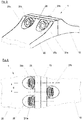
- the heads 31a and 31c are each countersunk in associated countersinks 27a and 27c, which are separated by a stiffening web 28.
- the stiffening web causes a further increased dimensional stability of the flange connection.
- the two components with the channels and the respectively guided through connecting elements are arranged according to a Gleitspiegelung, wherein the contact surfaces of the components represent the mirror plane.
- FIG. 4 a portion of the flange 1 is shown in a plan view.
- the inventive design of the components with oblique channels and their pivoting described above against each other allows a dense arrangement, ie a small distance d of adjacent connecting elements of the flange connection.
- a large number of connecting elements can be used and thus a high dimensional stability can be achieved.
- a component 10, 20 having a component section 11, 21 and a flange 13, 23 arranged on the component section for connecting the component to a further element.
- One or more oblique flange channels 14, 24 are arranged on the flange, ie channels each for receiving a portion of a connecting element 30 which extend obliquely to a surface region 12, 22 of the component section 11, 21 opposite the flange.
- a flange 1 with At least one such component 10, 20, a further component and at least one connecting element 30 is also disclosed a turbomachine with a housing which is composed of two or more components by means of such a flange 1.
Landscapes
- Engineering & Computer Science (AREA)
- General Engineering & Computer Science (AREA)
- Mechanical Engineering (AREA)
- Structures Of Non-Positive Displacement Pumps (AREA)
- Connection Of Plates (AREA)
Applications Claiming Priority (1)
| Application Number | Priority Date | Filing Date | Title |
|---|---|---|---|
| DE102017204539.6A DE102017204539A1 (de) | 2017-03-17 | 2017-03-17 | Schräger Flanschkanal |
Publications (2)
| Publication Number | Publication Date |
|---|---|
| EP3375986A1 true EP3375986A1 (fr) | 2018-09-19 |
| EP3375986B1 EP3375986B1 (fr) | 2023-04-05 |
Family
ID=61386764
Family Applications (1)
| Application Number | Title | Priority Date | Filing Date |
|---|---|---|---|
| EP18158778.3A Active EP3375986B1 (fr) | 2017-03-17 | 2018-02-27 | Composant de turbomachine |
Country Status (3)
| Country | Link |
|---|---|
| US (1) | US10393160B2 (fr) |
| EP (1) | EP3375986B1 (fr) |
| DE (1) | DE102017204539A1 (fr) |
Families Citing this family (3)
| Publication number | Priority date | Publication date | Assignee | Title |
|---|---|---|---|---|
| US11156112B2 (en) * | 2018-11-02 | 2021-10-26 | Chromalloy Gas Turbine Llc | Method and apparatus for mounting a transition duct in a gas turbine engine |
| US11092038B2 (en) | 2019-03-26 | 2021-08-17 | Raytheon Technologies Corporation | Notched axial flange for a split case compressor |
| US12492763B2 (en) | 2024-02-02 | 2025-12-09 | Pratt & Whitney Canada Corp. | Adaptive clamping apparatus |
Citations (4)
| Publication number | Priority date | Publication date | Assignee | Title |
|---|---|---|---|---|
| US2452227A (en) * | 1946-03-08 | 1948-10-26 | Allis Chalmers Mfg Co | Flanged joint |
| DE1217711B (de) * | 1961-02-01 | 1966-05-26 | Gen Electric Co Ltd | Dichte Flanschverbindung, insbesondere fuer Druckbehaelter |
| DE60037858T2 (de) * | 1999-10-08 | 2009-01-08 | Mitsubishi Heavy Industries, Ltd. | Verbindungsmittel für flanschlose Gehäusehälften |
| EP2048423A1 (fr) * | 2007-10-08 | 2009-04-15 | Siemens Aktiengesellschaft | Boîtier pour turbomachine et turbomachine associée |
Family Cites Families (4)
| Publication number | Priority date | Publication date | Assignee | Title |
|---|---|---|---|---|
| DE3837625C1 (fr) | 1988-11-05 | 1989-11-02 | Man Roland Druckmaschinen Ag, 6050 Offenbach, De | |
| DE4040125C2 (de) * | 1990-12-15 | 2000-01-20 | Walter Schmidt | Spritzkopf für einen Extruder |
| DE19728779C2 (de) | 1997-07-05 | 1999-09-09 | Ghh Borsig Turbomaschinen Gmbh | Verbindung für horizontal geteilte Gehäuse von Turbomaschinen |
| EP1162347A1 (fr) | 2000-06-09 | 2001-12-12 | Siemens Aktiengesellschaft | Trubine à vapeur avec un cartèr divisible |
-
2017
- 2017-03-17 DE DE102017204539.6A patent/DE102017204539A1/de not_active Withdrawn
-
2018
- 2018-02-27 EP EP18158778.3A patent/EP3375986B1/fr active Active
- 2018-03-13 US US15/919,781 patent/US10393160B2/en active Active
Patent Citations (4)
| Publication number | Priority date | Publication date | Assignee | Title |
|---|---|---|---|---|
| US2452227A (en) * | 1946-03-08 | 1948-10-26 | Allis Chalmers Mfg Co | Flanged joint |
| DE1217711B (de) * | 1961-02-01 | 1966-05-26 | Gen Electric Co Ltd | Dichte Flanschverbindung, insbesondere fuer Druckbehaelter |
| DE60037858T2 (de) * | 1999-10-08 | 2009-01-08 | Mitsubishi Heavy Industries, Ltd. | Verbindungsmittel für flanschlose Gehäusehälften |
| EP2048423A1 (fr) * | 2007-10-08 | 2009-04-15 | Siemens Aktiengesellschaft | Boîtier pour turbomachine et turbomachine associée |
Also Published As
| Publication number | Publication date |
|---|---|
| DE102017204539A1 (de) | 2018-09-20 |
| US20180266464A1 (en) | 2018-09-20 |
| EP3375986B1 (fr) | 2023-04-05 |
| US10393160B2 (en) | 2019-08-27 |
Similar Documents
| Publication | Publication Date | Title |
|---|---|---|
| EP3469212B1 (fr) | Rotor pour éolienne, pale de rotor pour éolienne, manchon et procédé de montage d'un rotor | |
| DE19518203C2 (de) | Einrichtung zur Aufnahme eines inneren Leitschaufelendes in einem Axialverdichter | |
| DE102008053936A1 (de) | Modifizierung von Gewindeprofilen für eine regulierte Steifigkeit | |
| CH652456A5 (de) | Kopfflanschbefestigungsvorrichtung fuer eine turbomaschine. | |
| EP3428402B1 (fr) | Segment d'aube directrice à joint de décharge courbé | |
| EP3375986B1 (fr) | Composant de turbomachine | |
| EP3181918B1 (fr) | Dispositif de fixation | |
| WO2018019832A1 (fr) | Élément de raccordement permettant de raccorder des sections de tour, section de tour, tour, éolienne ainsi que procédé de fabrication d'une section de tour et de raccordement de sections de tour | |
| EP3601865B1 (fr) | Raccord de tube | |
| EP3425195A1 (fr) | Pale de rotor d'éolienne divisible comprenant un module de douilles | |
| EP3735541B1 (fr) | Dispositif de fixation | |
| EP3176386A1 (fr) | Système de virole interne, virole interne, boîtier intermédiaire et turbomachine associés | |
| EP1707759B1 (fr) | Carter d'une turbomachine | |
| DE69517779T2 (de) | Elastische Kupplung für drehende Wellen | |
| EP2525077B1 (fr) | Buse | |
| EP3999749B1 (fr) | Palier à feuilles | |
| CH707746A2 (de) | Turbomaschineneinlass-Übergangssektion und modulares Turbomaschineneinlass-Baugruppensystem. | |
| EP3885535B1 (fr) | Bague d'étanchéité pour un rotor et rotor doté d'une telle bague d'étanchéité | |
| DE10021179C2 (de) | Vorrichtung zur axialen Befestigung eines Rohres | |
| DE102017116873A1 (de) | Windenergieanlagen-Stahlturmringsegment und Verfahren | |
| EP3927966B1 (fr) | Segment annulaire de tour en acier pour une partie de tour d'éolienne et procédé | |
| DE102019120362A1 (de) | Befestigungselement | |
| DE102004016244A1 (de) | Rotor für eine Turbomaschine | |
| EP3530965A1 (fr) | Agencement d'un corps creux et d'un élément de renforcement, procédé de fabrication dudit agencement ainsi qu'élément de renforcement | |
| EP4400713A1 (fr) | Pale de rotor d'éolienne divisée et procédé de liaison de deux segments de pale de rotor d'une pale de rotor d'éolienne |
Legal Events
| Date | Code | Title | Description |
|---|---|---|---|
| PUAI | Public reference made under article 153(3) epc to a published international application that has entered the european phase |
Free format text: ORIGINAL CODE: 0009012 |
|
| STAA | Information on the status of an ep patent application or granted ep patent |
Free format text: STATUS: THE APPLICATION HAS BEEN PUBLISHED |
|
| AK | Designated contracting states |
Kind code of ref document: A1 Designated state(s): AL AT BE BG CH CY CZ DE DK EE ES FI FR GB GR HR HU IE IS IT LI LT LU LV MC MK MT NL NO PL PT RO RS SE SI SK SM TR |
|
| AX | Request for extension of the european patent |
Extension state: BA ME |
|
| STAA | Information on the status of an ep patent application or granted ep patent |
Free format text: STATUS: REQUEST FOR EXAMINATION WAS MADE |
|
| 17P | Request for examination filed |
Effective date: 20190306 |
|
| RBV | Designated contracting states (corrected) |
Designated state(s): AL AT BE BG CH CY CZ DE DK EE ES FI FR GB GR HR HU IE IS IT LI LT LU LV MC MK MT NL NO PL PT RO RS SE SI SK SM TR |
|
| STAA | Information on the status of an ep patent application or granted ep patent |
Free format text: STATUS: EXAMINATION IS IN PROGRESS |
|
| 17Q | First examination report despatched |
Effective date: 20200324 |
|
| GRAP | Despatch of communication of intention to grant a patent |
Free format text: ORIGINAL CODE: EPIDOSNIGR1 |
|
| STAA | Information on the status of an ep patent application or granted ep patent |
Free format text: STATUS: GRANT OF PATENT IS INTENDED |
|
| INTG | Intention to grant announced |
Effective date: 20221123 |
|
| GRAS | Grant fee paid |
Free format text: ORIGINAL CODE: EPIDOSNIGR3 |
|
| GRAA | (expected) grant |
Free format text: ORIGINAL CODE: 0009210 |
|
| STAA | Information on the status of an ep patent application or granted ep patent |
Free format text: STATUS: THE PATENT HAS BEEN GRANTED |
|
| AK | Designated contracting states |
Kind code of ref document: B1 Designated state(s): AL AT BE BG CH CY CZ DE DK EE ES FI FR GB GR HR HU IE IS IT LI LT LU LV MC MK MT NL NO PL PT RO RS SE SI SK SM TR |
|
| REG | Reference to a national code |
Ref country code: GB Ref legal event code: FG4D Free format text: NOT ENGLISH |
|
| REG | Reference to a national code |
Ref country code: CH Ref legal event code: EP |
|
| REG | Reference to a national code |
Ref country code: AT Ref legal event code: REF Ref document number: 1558399 Country of ref document: AT Kind code of ref document: T Effective date: 20230415 |
|
| REG | Reference to a national code |
Ref country code: DE Ref legal event code: R096 Ref document number: 502018011882 Country of ref document: DE |
|
| REG | Reference to a national code |
Ref country code: IE Ref legal event code: FG4D Free format text: LANGUAGE OF EP DOCUMENT: GERMAN |
|
| REG | Reference to a national code |
Ref country code: LT Ref legal event code: MG9D |
|
| REG | Reference to a national code |
Ref country code: NL Ref legal event code: MP Effective date: 20230405 |
|
| PG25 | Lapsed in a contracting state [announced via postgrant information from national office to epo] |
Ref country code: NL Free format text: LAPSE BECAUSE OF FAILURE TO SUBMIT A TRANSLATION OF THE DESCRIPTION OR TO PAY THE FEE WITHIN THE PRESCRIBED TIME-LIMIT Effective date: 20230405 |
|
| PG25 | Lapsed in a contracting state [announced via postgrant information from national office to epo] |
Ref country code: SE Free format text: LAPSE BECAUSE OF FAILURE TO SUBMIT A TRANSLATION OF THE DESCRIPTION OR TO PAY THE FEE WITHIN THE PRESCRIBED TIME-LIMIT Effective date: 20230405 Ref country code: PT Free format text: LAPSE BECAUSE OF FAILURE TO SUBMIT A TRANSLATION OF THE DESCRIPTION OR TO PAY THE FEE WITHIN THE PRESCRIBED TIME-LIMIT Effective date: 20230807 Ref country code: NO Free format text: LAPSE BECAUSE OF FAILURE TO SUBMIT A TRANSLATION OF THE DESCRIPTION OR TO PAY THE FEE WITHIN THE PRESCRIBED TIME-LIMIT Effective date: 20230705 Ref country code: ES Free format text: LAPSE BECAUSE OF FAILURE TO SUBMIT A TRANSLATION OF THE DESCRIPTION OR TO PAY THE FEE WITHIN THE PRESCRIBED TIME-LIMIT Effective date: 20230405 |
|
| PG25 | Lapsed in a contracting state [announced via postgrant information from national office to epo] |
Ref country code: RS Free format text: LAPSE BECAUSE OF FAILURE TO SUBMIT A TRANSLATION OF THE DESCRIPTION OR TO PAY THE FEE WITHIN THE PRESCRIBED TIME-LIMIT Effective date: 20230405 Ref country code: PL Free format text: LAPSE BECAUSE OF FAILURE TO SUBMIT A TRANSLATION OF THE DESCRIPTION OR TO PAY THE FEE WITHIN THE PRESCRIBED TIME-LIMIT Effective date: 20230405 Ref country code: LV Free format text: LAPSE BECAUSE OF FAILURE TO SUBMIT A TRANSLATION OF THE DESCRIPTION OR TO PAY THE FEE WITHIN THE PRESCRIBED TIME-LIMIT Effective date: 20230405 Ref country code: LT Free format text: LAPSE BECAUSE OF FAILURE TO SUBMIT A TRANSLATION OF THE DESCRIPTION OR TO PAY THE FEE WITHIN THE PRESCRIBED TIME-LIMIT Effective date: 20230405 Ref country code: IS Free format text: LAPSE BECAUSE OF FAILURE TO SUBMIT A TRANSLATION OF THE DESCRIPTION OR TO PAY THE FEE WITHIN THE PRESCRIBED TIME-LIMIT Effective date: 20230805 Ref country code: HR Free format text: LAPSE BECAUSE OF FAILURE TO SUBMIT A TRANSLATION OF THE DESCRIPTION OR TO PAY THE FEE WITHIN THE PRESCRIBED TIME-LIMIT Effective date: 20230405 Ref country code: GR Free format text: LAPSE BECAUSE OF FAILURE TO SUBMIT A TRANSLATION OF THE DESCRIPTION OR TO PAY THE FEE WITHIN THE PRESCRIBED TIME-LIMIT Effective date: 20230706 Ref country code: AL Free format text: LAPSE BECAUSE OF FAILURE TO SUBMIT A TRANSLATION OF THE DESCRIPTION OR TO PAY THE FEE WITHIN THE PRESCRIBED TIME-LIMIT Effective date: 20230405 |
|
| PG25 | Lapsed in a contracting state [announced via postgrant information from national office to epo] |
Ref country code: FI Free format text: LAPSE BECAUSE OF FAILURE TO SUBMIT A TRANSLATION OF THE DESCRIPTION OR TO PAY THE FEE WITHIN THE PRESCRIBED TIME-LIMIT Effective date: 20230405 |
|
| REG | Reference to a national code |
Ref country code: DE Ref legal event code: R097 Ref document number: 502018011882 Country of ref document: DE |
|
| PG25 | Lapsed in a contracting state [announced via postgrant information from national office to epo] |
Ref country code: SK Free format text: LAPSE BECAUSE OF FAILURE TO SUBMIT A TRANSLATION OF THE DESCRIPTION OR TO PAY THE FEE WITHIN THE PRESCRIBED TIME-LIMIT Effective date: 20230405 |
|
| PG25 | Lapsed in a contracting state [announced via postgrant information from national office to epo] |
Ref country code: SM Free format text: LAPSE BECAUSE OF FAILURE TO SUBMIT A TRANSLATION OF THE DESCRIPTION OR TO PAY THE FEE WITHIN THE PRESCRIBED TIME-LIMIT Effective date: 20230405 Ref country code: SK Free format text: LAPSE BECAUSE OF FAILURE TO SUBMIT A TRANSLATION OF THE DESCRIPTION OR TO PAY THE FEE WITHIN THE PRESCRIBED TIME-LIMIT Effective date: 20230405 Ref country code: RO Free format text: LAPSE BECAUSE OF FAILURE TO SUBMIT A TRANSLATION OF THE DESCRIPTION OR TO PAY THE FEE WITHIN THE PRESCRIBED TIME-LIMIT Effective date: 20230405 Ref country code: EE Free format text: LAPSE BECAUSE OF FAILURE TO SUBMIT A TRANSLATION OF THE DESCRIPTION OR TO PAY THE FEE WITHIN THE PRESCRIBED TIME-LIMIT Effective date: 20230405 Ref country code: DK Free format text: LAPSE BECAUSE OF FAILURE TO SUBMIT A TRANSLATION OF THE DESCRIPTION OR TO PAY THE FEE WITHIN THE PRESCRIBED TIME-LIMIT Effective date: 20230405 Ref country code: CZ Free format text: LAPSE BECAUSE OF FAILURE TO SUBMIT A TRANSLATION OF THE DESCRIPTION OR TO PAY THE FEE WITHIN THE PRESCRIBED TIME-LIMIT Effective date: 20230405 |
|
| PLBE | No opposition filed within time limit |
Free format text: ORIGINAL CODE: 0009261 |
|
| STAA | Information on the status of an ep patent application or granted ep patent |
Free format text: STATUS: NO OPPOSITION FILED WITHIN TIME LIMIT |
|
| 26N | No opposition filed |
Effective date: 20240108 |
|
| PG25 | Lapsed in a contracting state [announced via postgrant information from national office to epo] |
Ref country code: SI Free format text: LAPSE BECAUSE OF FAILURE TO SUBMIT A TRANSLATION OF THE DESCRIPTION OR TO PAY THE FEE WITHIN THE PRESCRIBED TIME-LIMIT Effective date: 20230405 |
|
| PG25 | Lapsed in a contracting state [announced via postgrant information from national office to epo] |
Ref country code: SI Free format text: LAPSE BECAUSE OF FAILURE TO SUBMIT A TRANSLATION OF THE DESCRIPTION OR TO PAY THE FEE WITHIN THE PRESCRIBED TIME-LIMIT Effective date: 20230405 Ref country code: IT Free format text: LAPSE BECAUSE OF FAILURE TO SUBMIT A TRANSLATION OF THE DESCRIPTION OR TO PAY THE FEE WITHIN THE PRESCRIBED TIME-LIMIT Effective date: 20230405 |
|
| PG25 | Lapsed in a contracting state [announced via postgrant information from national office to epo] |
Ref country code: MC Free format text: LAPSE BECAUSE OF FAILURE TO SUBMIT A TRANSLATION OF THE DESCRIPTION OR TO PAY THE FEE WITHIN THE PRESCRIBED TIME-LIMIT Effective date: 20230405 |
|
| REG | Reference to a national code |
Ref country code: CH Ref legal event code: PL |
|
| PG25 | Lapsed in a contracting state [announced via postgrant information from national office to epo] |
Ref country code: LU Free format text: LAPSE BECAUSE OF NON-PAYMENT OF DUE FEES Effective date: 20240227 |
|
| PG25 | Lapsed in a contracting state [announced via postgrant information from national office to epo] |
Ref country code: CH Free format text: LAPSE BECAUSE OF NON-PAYMENT OF DUE FEES Effective date: 20240229 |
|
| PG25 | Lapsed in a contracting state [announced via postgrant information from national office to epo] |
Ref country code: LU Free format text: LAPSE BECAUSE OF NON-PAYMENT OF DUE FEES Effective date: 20240227 Ref country code: CH Free format text: LAPSE BECAUSE OF NON-PAYMENT OF DUE FEES Effective date: 20240229 |
|
| PG25 | Lapsed in a contracting state [announced via postgrant information from national office to epo] |
Ref country code: BG Free format text: LAPSE BECAUSE OF FAILURE TO SUBMIT A TRANSLATION OF THE DESCRIPTION OR TO PAY THE FEE WITHIN THE PRESCRIBED TIME-LIMIT Effective date: 20230405 |
|
| PG25 | Lapsed in a contracting state [announced via postgrant information from national office to epo] |
Ref country code: BG Free format text: LAPSE BECAUSE OF FAILURE TO SUBMIT A TRANSLATION OF THE DESCRIPTION OR TO PAY THE FEE WITHIN THE PRESCRIBED TIME-LIMIT Effective date: 20230405 |
|
| REG | Reference to a national code |
Ref country code: BE Ref legal event code: MM Effective date: 20240229 |
|
| PG25 | Lapsed in a contracting state [announced via postgrant information from national office to epo] |
Ref country code: BE Free format text: LAPSE BECAUSE OF NON-PAYMENT OF DUE FEES Effective date: 20240229 |
|
| PG25 | Lapsed in a contracting state [announced via postgrant information from national office to epo] |
Ref country code: IE Free format text: LAPSE BECAUSE OF NON-PAYMENT OF DUE FEES Effective date: 20240227 |
|
| PG25 | Lapsed in a contracting state [announced via postgrant information from national office to epo] |
Ref country code: IE Free format text: LAPSE BECAUSE OF NON-PAYMENT OF DUE FEES Effective date: 20240227 Ref country code: BE Free format text: LAPSE BECAUSE OF NON-PAYMENT OF DUE FEES Effective date: 20240229 |
|
| PGFP | Annual fee paid to national office [announced via postgrant information from national office to epo] |
Ref country code: DE Payment date: 20250218 Year of fee payment: 8 |
|
| REG | Reference to a national code |
Ref country code: AT Ref legal event code: MM01 Ref document number: 1558399 Country of ref document: AT Kind code of ref document: T Effective date: 20240227 |
|
| PG25 | Lapsed in a contracting state [announced via postgrant information from national office to epo] |
Ref country code: AT Free format text: LAPSE BECAUSE OF NON-PAYMENT OF DUE FEES Effective date: 20240227 |
|
| PGFP | Annual fee paid to national office [announced via postgrant information from national office to epo] |
Ref country code: FR Payment date: 20250221 Year of fee payment: 8 |
|
| PGFP | Annual fee paid to national office [announced via postgrant information from national office to epo] |
Ref country code: GB Payment date: 20250220 Year of fee payment: 8 |
|
| PG25 | Lapsed in a contracting state [announced via postgrant information from national office to epo] |
Ref country code: CY Free format text: LAPSE BECAUSE OF FAILURE TO SUBMIT A TRANSLATION OF THE DESCRIPTION OR TO PAY THE FEE WITHIN THE PRESCRIBED TIME-LIMIT; INVALID AB INITIO Effective date: 20180227 |
|
| PG25 | Lapsed in a contracting state [announced via postgrant information from national office to epo] |
Ref country code: HU Free format text: LAPSE BECAUSE OF FAILURE TO SUBMIT A TRANSLATION OF THE DESCRIPTION OR TO PAY THE FEE WITHIN THE PRESCRIBED TIME-LIMIT; INVALID AB INITIO Effective date: 20180227 |
|
| PG25 | Lapsed in a contracting state [announced via postgrant information from national office to epo] |
Ref country code: TR Free format text: LAPSE BECAUSE OF FAILURE TO SUBMIT A TRANSLATION OF THE DESCRIPTION OR TO PAY THE FEE WITHIN THE PRESCRIBED TIME-LIMIT Effective date: 20230405 |