EP4400713A1 - Pale de rotor d'éolienne divisée et procédé de liaison de deux segments de pale de rotor d'une pale de rotor d'éolienne - Google Patents
Pale de rotor d'éolienne divisée et procédé de liaison de deux segments de pale de rotor d'une pale de rotor d'éolienne Download PDFInfo
- Publication number
- EP4400713A1 EP4400713A1 EP24151137.7A EP24151137A EP4400713A1 EP 4400713 A1 EP4400713 A1 EP 4400713A1 EP 24151137 A EP24151137 A EP 24151137A EP 4400713 A1 EP4400713 A1 EP 4400713A1
- Authority
- EP
- European Patent Office
- Prior art keywords
- rotor blade
- connecting flange
- wind turbine
- blade segment
- segment
- Prior art date
- Legal status (The legal status is an assumption and is not a legal conclusion. Google has not performed a legal analysis and makes no representation as to the accuracy of the status listed.)
- Pending
Links
- 238000000034 method Methods 0.000 title claims abstract description 12
- 238000007789 sealing Methods 0.000 claims description 12
- 230000036316 preload Effects 0.000 description 3
- 238000013461 design Methods 0.000 description 2
- 238000010586 diagram Methods 0.000 description 2
- 239000000835 fiber Substances 0.000 description 2
- 230000003993 interaction Effects 0.000 description 2
- 238000004519 manufacturing process Methods 0.000 description 2
- 230000007704 transition Effects 0.000 description 2
- 239000004606 Fillers/Extenders Substances 0.000 description 1
- 229910000831 Steel Inorganic materials 0.000 description 1
- 230000005540 biological transmission Effects 0.000 description 1
- 230000015572 biosynthetic process Effects 0.000 description 1
- 239000002131 composite material Substances 0.000 description 1
- 239000004020 conductor Substances 0.000 description 1
- 238000010276 construction Methods 0.000 description 1
- 238000005260 corrosion Methods 0.000 description 1
- 230000007797 corrosion Effects 0.000 description 1
- 238000011161 development Methods 0.000 description 1
- 230000018109 developmental process Effects 0.000 description 1
- 230000000694 effects Effects 0.000 description 1
- 239000000463 material Substances 0.000 description 1
- 238000005259 measurement Methods 0.000 description 1
- 238000012856 packing Methods 0.000 description 1
- 230000011218 segmentation Effects 0.000 description 1
- 239000011265 semifinished product Substances 0.000 description 1
- 125000006850 spacer group Chemical group 0.000 description 1
- 239000010959 steel Substances 0.000 description 1
Images



Classifications
-
- F—MECHANICAL ENGINEERING; LIGHTING; HEATING; WEAPONS; BLASTING
- F03—MACHINES OR ENGINES FOR LIQUIDS; WIND, SPRING, OR WEIGHT MOTORS; PRODUCING MECHANICAL POWER OR A REACTIVE PROPULSIVE THRUST, NOT OTHERWISE PROVIDED FOR
- F03D—WIND MOTORS
- F03D1/00—Wind motors with rotation axis substantially parallel to the air flow entering the rotor
- F03D1/06—Rotors
- F03D1/065—Rotors characterised by their construction elements
- F03D1/0675—Rotors characterised by their construction elements of the blades
- F03D1/0677—Longitudinally segmented blades; Connectors therefor
-
- F—MECHANICAL ENGINEERING; LIGHTING; HEATING; WEAPONS; BLASTING
- F05—INDEXING SCHEMES RELATING TO ENGINES OR PUMPS IN VARIOUS SUBCLASSES OF CLASSES F01-F04
- F05B—INDEXING SCHEME RELATING TO WIND, SPRING, WEIGHT, INERTIA OR LIKE MOTORS, TO MACHINES OR ENGINES FOR LIQUIDS COVERED BY SUBCLASSES F03B, F03D AND F03G
- F05B2230/00—Manufacture
- F05B2230/60—Assembly methods
-
- F—MECHANICAL ENGINEERING; LIGHTING; HEATING; WEAPONS; BLASTING
- F05—INDEXING SCHEMES RELATING TO ENGINES OR PUMPS IN VARIOUS SUBCLASSES OF CLASSES F01-F04
- F05B—INDEXING SCHEME RELATING TO WIND, SPRING, WEIGHT, INERTIA OR LIKE MOTORS, TO MACHINES OR ENGINES FOR LIQUIDS COVERED BY SUBCLASSES F03B, F03D AND F03G
- F05B2260/00—Function
- F05B2260/30—Retaining components in desired mutual position
- F05B2260/301—Retaining bolts or nuts
Definitions
- the invention relates to a split wind turbine rotor blade and a method for connecting two rotor blade segments of a wind turbine rotor blade.
- Wind turbines with wind turbine rotor blades are widely known from the prior art and are used to convert wind energy into electrical energy.
- a rotor blade can be designed as a split or segmented rotor blade, in which rotor blade segments are arranged in the longitudinal direction of the rotor blade and joined together in the area of the division point.
- Mechanical connections are generally used to connect the two rotor blade segments.
- a large number of connecting elements integrated into the laminate are provided for each rotor blade segment, by means of which the rotor blade segments can be connected to one another.
- Fasteners such as fastening screw bolts or the like are typically used here.
- the connecting elements are located in the laminate of a respective connection end or division flange of the rotor blade segments.
- the rotor blade segments can be connected to one another directly or via suitable spacers.
- the primary structures made of fiber composite construction, which consist of, for example, high-strength and high-stiffness continuous fibers and highly technological and precise semi-finished products (such as pultrudates), are typically reassembled.
- Particularly high forces such as several thousand kN in complex load cases, must be transferred from the tip segment (so-called tip segment) to the root segment via the corresponding mechanical connection measure.
- An object underlying the invention is to provide a concept for a split rotor blade which reduces or even avoids the above-mentioned disadvantages.
- a wind turbine rotor blade which is formed by a first rotor blade segment and a second rotor blade segment.
- the first rotor blade segment has a first connection end with first connecting elements.
- the second rotor blade segment has a second connection end with second connecting elements.
- a first connecting flange is mounted on the first rotor blade segment by means of the first connecting elements.
- a second connecting flange is mounted on the second rotor blade segment by means of the second connecting elements. The two connecting flanges are brought into engagement with one another in a form-fitting manner, so that the two rotor blade segments are connected to one another in a torsionally rigid manner.
- connecting elements can be, for example, so-called inserts, cross bolts for a so-called "IKEA connection" or the like.
- the connecting flanges are then brought into engagement with one another and firmly connected.
- the respective connections are mechanical in nature, whereby fastening means such as screw bolts or the like can be used.
- Appropriate assembly tools are used, for example (hydraulic) clamping tools.
- the connecting elements are, for example, connecting elements embedded in or fixed to the blade shells of the rotor blade or its rotor blade segments, such as bearing sleeves, threaded sleeves or the like. Bearing sleeves with internal threads or through holes are preferably used.
- the connecting elements of one rotor blade segment can be similar to the connecting elements of the other rotor blade segment or be different.
- Bolts such as screw bolts or threaded bolts, are used in particular as fastening means.
- longitudinal bolts are used to screw the connecting flanges axially, i.e. along the longitudinal axis of the rotor blade, to the respective rotor blade segment.
- the two connecting flanges are preferably screwed together with transverse bolts.
- the form fit means that the two connecting flanges have a shape that corresponds to one another, allowing them to be joined together, with only one degree of freedom in the translational joining direction before the two connecting flanges are firmly connected, for example screwed together. Further degrees of freedom in a translational or rotational manner are prevented by the formation of the form fit.
- the form fit therefore makes it possible in particular to absorb torsional forces or moments that act in the dividing point when the rotor blade is twisted around the longitudinal axis.
- the first connecting flange and the second connecting flange are pushed axially into one another to form the positive engagement.
- the two connecting flanges are pushed into one another in the axial direction, ie along the longitudinal axis of the rotor blade, for assembly. This means that there is an axial degree of freedom before the connecting flanges are fixed to each other.
- the first connecting flange has ribs, projections, edges, grooves or contours as first positive locking elements and the second connecting flange has corresponding second positive locking elements.
- the first and second positive locking elements are provided in a large number, for example, and are arranged distributed along the circumference of the rotor blade, for example. This enables the advantages and functions mentioned above.
- the first connecting flange or the second connecting flange forms an outer side in the form-fitting engagement, which in each case ends essentially flush with the adjacent outer surface of the first rotor blade segment and the second rotor blade segment. This results in an aerodynamically particularly effective design of the rotor blade in the region of the division point.
- the first connecting flange is connected to the first connecting elements of the first rotor blade segment via longitudinal connecting means and the second connecting flange is connected to the second connecting elements of the second rotor blade segment via longitudinal connecting means, while the first connecting flange and the second connecting flange are connected to one another via transverse connecting means.
- the longitudinal connecting means are, for example, the bolts or screw bolts mentioned at the beginning, which form a connection to the connecting elements along the longitudinal axis of the rotor blade.
- the cross-connecting means are, for example, also the bolts or screw bolts mentioned at the beginning, which connect the two connecting flanges in a direction that runs essentially transversely to the longitudinal axis of the rotor blade.
- the cross-connecting means can also be designed as rivets.
- the respective longitudinal and/or cross-connecting means can be screwed directly into a fixed thread or screwed via nuts. For example, the connecting elements or some of the connecting elements have such fixed threads.
- the cross-connection means are cross-screw bolts and for connecting the two connecting flanges, one of the two connecting flanges has threads for the cross-screw bolts, while the other of the two connecting flanges has through-holes for the cross-screw bolts.
- the cross-connecting means are arranged in two rows along the circumferential direction of the rotor blade on the suction and pressure side of the connecting flanges. This achieves a particularly rigid and secure connection.
- Other arrangements are also conceivable, such as a single-row or three- or multi-row arrangement.
- arrangements are conceivable in which the cross-connecting means are provided offset from one another along the circumference in a two- or multi-row arrangement.
- each connecting flange is formed from a separate suction-side and a pressure-side connecting flange section, which are each connected on the suction side and the pressure side to the respective rotor blade segment via the respective connecting elements. This provides greater assembly flexibility, whereby tolerances can be compensated particularly well.
- the suction-side and pressure-side sections of the first connecting flange are connected to one another by means of cross-connecting means in the area of the nose and/or in the area of the end edge of the rotor blade.
- cross-connecting means in the area of the nose and/or in the area of the end edge of the rotor blade.
- an end edge or nose edge screw connection is achieved.
- In the area means directly on or near the end/nose edge. This achieves a particularly stable design in the area of the respective edges.
- the suction-side and pressure-side sections of a connecting flange are connected to an end edge element.
- the end edge element can be made in one piece or in multiple parts.
- the connection can be made using the above cross-connecting means, which then firmly connect both the end edge element and the sections of the connecting flange. This offers the possibility of using a special end edge piece which differs from the connecting flange, for example in terms of material and/or elasticity. This makes it possible to achieve special aerodynamic effects.
- the first and second connecting flanges are each formed by a closed ring-like structure that follows the rotor blade contour. This enables particularly quick assembly, since each connecting flange is formed in one piece. Furthermore, no additional connection is required at the leading and trailing edges. Furthermore, there is no gaping joint between the two flanges.
- the first and second connecting flanges are designed to be electrically conductive. This provides a simple way of electrically conducting a lightning conductor from the rotor blade tip across the dividing point to the rotor blade root. In other words, no additional measures for the electrical conduction need to be provided at the dividing point.
- the joint between the first connecting flange and the first rotor blade segment and/or the joint between the second connecting flange and the second rotor blade segment are each sealed with a sealing element.
- the sealing element is designed as a ring-like seal or one or more sealing strips. In particular, this can be used to seal a gap between the respective connecting flange and the connecting elements at the respective connection end of the corresponding rotor blade segment. This serves in particular to protect against corrosion.
- FIG. 1 shows a schematic representation of a wind turbine 100.
- the wind turbine 100 has a tower 102.
- the tower 102 is attached to a base by means of a foundation 104.
- a nacelle 106 is rotatably mounted at an end of the tower 102 opposite the base.
- the nacelle 106 has, for example, a generator which is coupled to a rotor 108 via a rotor shaft (not shown).
- the rotor 108 has one or more (wind turbine) rotor blades 110 which are arranged on a rotor hub 112.
- the rotor 108 is set in rotation by an air flow, for example wind. This rotational movement is transmitted to the generator via the rotor shaft and, if necessary, a gear.
- the generator converts the kinetic energy of the rotor 108 into electrical energy.
- FIG. 2 shows an exemplary wind turbine rotor blade 110.
- the rotor blade 110 has the shape of a conventional rotor blade and has a rotor blade root region 114 that faces the rotor hub 112.
- the rotor blade root region 114 typically has a substantially circular cross-section.
- the rotor blade root region 114 is followed by a transition region 116 and a profile region 118 of the rotor blade 110.
- the rotor blade 110 has a pressure side 122 and an opposite suction side 124 with respect to a longitudinal extension direction 120 (also main extension direction or longitudinal axis).
- the rotor blade 110 is essentially hollow on the inside.
- a rotor blade connection end 126 with a flange connection 128 by means of which the rotor blade 110 is mechanically connected to a pitch bearing or an extender.
- the rotor blade 110 has a division point 130 at which a rotor blade segment 132 on the blade root side and a rotor blade segment 134 on the blade tip side are connected to one another.
- both segments 132, 134 each have a connection end 136, 138 (also segment connection areas).
- the rotor blade 110 is thus a split rotor blade as described above.
- Each connection end 136, 138 has a plurality of connecting elements 140, 142 in the form of inserts, for example bearing sleeves, which are arranged in the circumferential direction following the profile and are designed to receive screw bolts, also called bearing bolts or connecting bolts.
- the first connecting elements 140 have first internal threads and the second connecting elements 142 have second internal threads, or vice versa.
- connection end 136, 138 is realized, for example, as a flange insert, which is inserted as an insert into a production mold for producing the rotor blade 110.
- a flange insert which is inserted as an insert into a production mold for producing the rotor blade 110.
- no flange insert is provided and the bearing sleeves are embedded and laminated directly into the rotor blade half shells.
- the bearing sleeves are, for example, steel sleeves.
- Figure 3 shows a schematic sectional view in a partial area of two connected rotor blade segments 132, 134 at the dividing point 130, wherein a single bolt connection 148 is shown.
- the first connection end 136 of the first rotor blade segment 132 has the plurality of first connecting elements 140 and the second connection end 138 of the second rotor blade segment 134 has the plurality of second connecting elements 142.
- a connecting bolt 146 is screwed into a pair of first and second connecting elements 140, 142 arranged in alignment with one another, which connects the two connection ends 136, 138 and thus the two rotor blade segments 132, 134 in a mechanically fixed manner.
- a pressure piece 144 is clamped between the two connection ends 136, 138 for each bolt connection 148.
- Figure 4 shows a perspective exploded view of the first rotor blade segment 132 of the rotor blade 110 (not shown in full).
- the first rotor blade segment 132 has the first connection end 136 at the dividing point 130 of the rotor blade 110.
- the first connection end 136 has a plurality of first connecting elements 140 which Profile are arranged along the circumference.
- the first connecting elements 140 are laminated bearing sleeves which have through holes for screwing using longitudinal bolt sets 150 as the longitudinal connecting means mentioned above.
- the longitudinal bolt sets 150 comprise longitudinal screw bolts 151 which are fastened via nuts and washers (see Figure 6 ) can be connected to the first connecting elements 140.
- the first connecting elements have internal threads (so-called fixed threads) and the longitudinal screw bolts are screwed directly into the connecting elements.
- the first connecting flange 154 is formed by two separate sections for the pressure side 122 and suction side 124, namely a suction-side connecting flange section 158 and a pressure-side connecting flange section 160.
- Figure 5 shows a perspective view of the first rotor blade segment 132 in an assembled state.
- the end edge element 152 and the first connecting flange 154 are arranged accordingly on the first connection end 136 and the first connecting flange 154, i.e. both connecting flange sections 158 and 160, is firmly screwed to the first rotor blade segment 132 by means of the longitudinal bolt sets 150.
- a web 162 of the rotor blade 110 it can be seen in Figure 5 a web 162 of the rotor blade 110.
- the sealing element 156 can be seen, which seals the joint 164 between the first connecting flange 154 and the first rotor blade segment 132.
- Figure 6 represents a perspective detailed view of the Figure 5 , which shows the connection between the pressure-side connecting flange section 160 and the connecting elements 140 in an enlarged view.
- the screw connection for each connecting element 140 is made using a longitudinal screw bolt 151 in conjunction with a nut 166 and a disk 168. Each or individual disks 168 can be used to measure a preload force.
- the first connecting flange 154 has first form-locking elements 170. These serve to interact with corresponding elements of the second rotor blade segment 134.
- the first form-locking elements 170 are designed as ribs or projections in the exemplary embodiment.
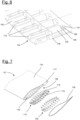
- FIGS 7 to 9 show the second rotor blade segment 134 corresponding to the first rotor blade segment 132 in similar representations.
- the second inserts 142 are arranged at the second connection end 138.
- a further end edge element 172 is provided, which interacts with the end edge element 152 of the first rotor blade segment 132.
- a second connecting flange 174 is provided, which is formed by a suction-side connecting flange section 176 and a pressure-side connecting flange section 178.
- Bolt sets 150 and a sealing element 156 are again provided, the latter sealing the joint 179 between the second connection end 138 and the second connecting flange 174.
- the second connecting flange 174 has second form-locking elements 180 which are designed as grooves or channels.
- the second form-locking elements 180 are designed such that these interact in a form-fitting manner with the first form-locking elements 170.
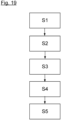
- a first step S1 of the method according to an embodiment of the invention (see Figure 19 ), the first connecting flange 154 is mounted to the first rotor blade segment 132 as described above.
- This step S1 may include further measures such as attaching or attaching the first end edge element 152.
- a second step S2 the second connecting flange 174 is mounted on the second connection end 136 in a similar manner to the first connecting flange 154.
- This step S2 may include further measures such as attaching or attaching the second end edge element 172.
- steps S1 and S2 can of course also be swapped.
- the two steps S1 and S2 are preferably carried out in a manufacturer's factory (under controlled conditions) so that assembly in the field, i.e. when installing a wind turbine 100, is significantly more efficient and effective.
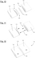
- a third step S3 the two rotor blade segments 132, 134 are positioned such that they are opposite each other.
- This is shown in Figure 10 which additionally shows cross bolts 182 as cross connecting means and associated bolt seals 184 (covers).
- a fourth step S4 the two rotor blade segments 132, 134 are moved relative to each other so that the two connecting flanges 154 and 174 interlock in a form-fitting manner.
- the connecting flanges 154, 174 form counterparts to one another, so to speak.
- the two connecting flanges 154 and 174 are pushed together axially.
- the first form-fitting elements 170 are received in the second form-fitting elements 180.
- Figure 12 represents the pushed-together state, wherein the further end edge element 172 of the second rotor blade segment 134 is positively received in the end edge element 152 of the first rotor blade segment 132.
- the positive locking in particular achieves simple self-centering or self-alignment.
- the rotor blade segments 132, 134 are pushed together in particular with abutment.
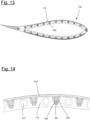
- Figure 13 shows a cross section of the collapsed state according to Figure 12 at the division point 130. The positive interaction of the form-locking elements 170 and 180 can be seen.
- a fifth step S5 the two connecting flanges 154 and 174 are firmly screwed together using the cross bolts 182 and the seals 184 are mounted.
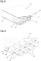
- Figures 14 and 15 show detailed views of the division point 130.
- Each transverse screw bolt 182 is screwed from outside the rotor blade 110 transversely to the longitudinal axis 126 through a corresponding through hole 183 of the first connecting flange 154 into a corresponding thread 185 of the second connecting flange 174.
- Figure 15 It can also be seen that the cross bolts 182, which are each covered by the bolt seals 184, are arranged in two rows. In particular, for each form-fitting connection of a first Two transverse screw bolts 182 are provided for connecting the form-locking element 170 with a second form-locking element 180.
- the first connecting flange 154 is flush on its outer side 190 with the adjacent outer surfaces 192 of the two rotor blade segments 132, 134.
- the two connecting flanges 154, 175 are designed to be electrically conductive and are in electrically conductive contact due to their connection to one another. This can be used to create an electrical connection from one rotor blade segment to the other, for example for a lightning rod.
- Figure 16 again shows a perspective view of the division point 130 with mounted connecting flanges 154, 174.
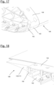
- Figure 17 shows the detail Y according to Figure 16 , which shows the connection of the suction-side connecting flange section 158 with the pressure-side connecting flange section 160 by means of cross bolts 182 at the nose edge 186.
- Figure 18 shows the detail Z according to Figure 16 , which shows the connection of the suction-side connecting flange section 158 with the pressure-side connecting flange section 160 by means of cross bolts 182 at the end edge 188. is the simultaneous screwing of end edge 188 and nose edge 186 by means of cross bolt 182.
Landscapes
- Engineering & Computer Science (AREA)
- Life Sciences & Earth Sciences (AREA)
- Sustainable Development (AREA)
- Sustainable Energy (AREA)
- Chemical & Material Sciences (AREA)
- Combustion & Propulsion (AREA)
- Mechanical Engineering (AREA)
- General Engineering & Computer Science (AREA)
- Wind Motors (AREA)
Applications Claiming Priority (1)
| Application Number | Priority Date | Filing Date | Title |
|---|---|---|---|
| DE102023100609.6A DE102023100609A1 (de) | 2023-01-12 | 2023-01-12 | Geteiltes Windenergieanlagenrotorblatt sowie Verfahren zum Verbinden zweier Rotorblattsegmente eines Windenergieanlagenrotorblatts |
Publications (1)
| Publication Number | Publication Date |
|---|---|
| EP4400713A1 true EP4400713A1 (fr) | 2024-07-17 |
Family
ID=89573662
Family Applications (1)
| Application Number | Title | Priority Date | Filing Date |
|---|---|---|---|
| EP24151137.7A Pending EP4400713A1 (fr) | 2023-01-12 | 2024-01-10 | Pale de rotor d'éolienne divisée et procédé de liaison de deux segments de pale de rotor d'une pale de rotor d'éolienne |
Country Status (2)
| Country | Link |
|---|---|
| EP (1) | EP4400713A1 (fr) |
| DE (1) | DE102023100609A1 (fr) |
Citations (6)
| Publication number | Priority date | Publication date | Assignee | Title |
|---|---|---|---|---|
| US20120141287A1 (en) * | 2011-08-29 | 2012-06-07 | General Electric Company | Wind turbine rotor blade joint |
| US20140271210A1 (en) * | 2011-05-13 | 2014-09-18 | Investigaciones Y Desarrollos Eolicos, S.L. | Connection system for connecting component sections of wind turbine blades |
| WO2015124568A1 (fr) | 2014-02-18 | 2015-08-27 | Lm Wp Patent Holding A/S | Système de manchon de pale de turbine éolienne |
| US9822759B2 (en) * | 2013-01-10 | 2017-11-21 | Ingenieria Prosix, S. L. | Fixation for a wind turbine blade to the hub |
| WO2022042809A1 (fr) * | 2020-08-28 | 2022-03-03 | Vestas Wind Systems A/S | Joint d'assemblage pour une pale d'éolienne fendue |
| EP3974643A1 (fr) * | 2020-09-25 | 2022-03-30 | Siemens Gamesa Renewable Energy Innovation & Technology S.L. | Pale de rotor d'une éolienne et éolienne |
Family Cites Families (5)
| Publication number | Priority date | Publication date | Assignee | Title |
|---|---|---|---|---|
| DE2921152C2 (de) * | 1979-05-25 | 1982-04-22 | Messerschmitt-Bölkow-Blohm GmbH, 8000 München | Rotorblatt für Windkraftwerke |
| DE102010039778B4 (de) * | 2010-08-25 | 2018-03-01 | Skywind Gmbh | Rotorblatt für Windenergieanlagen |
| US7922454B1 (en) * | 2010-10-29 | 2011-04-12 | General Electric Company | Joint design for rotor blade segments of a wind turbine |
| DE102018103344A1 (de) * | 2018-02-14 | 2019-08-14 | Wobben Properties Gmbh | Verfahren zur Herstellung eines geteilten Rotorblatts und Rotorblatt |
| ES1218380Y (es) * | 2018-07-25 | 2018-12-26 | Emprending Business S L | Pala divisible para aerogeneradores |
-
2023
- 2023-01-12 DE DE102023100609.6A patent/DE102023100609A1/de active Pending
-
2024
- 2024-01-10 EP EP24151137.7A patent/EP4400713A1/fr active Pending
Patent Citations (6)
| Publication number | Priority date | Publication date | Assignee | Title |
|---|---|---|---|---|
| US20140271210A1 (en) * | 2011-05-13 | 2014-09-18 | Investigaciones Y Desarrollos Eolicos, S.L. | Connection system for connecting component sections of wind turbine blades |
| US20120141287A1 (en) * | 2011-08-29 | 2012-06-07 | General Electric Company | Wind turbine rotor blade joint |
| US9822759B2 (en) * | 2013-01-10 | 2017-11-21 | Ingenieria Prosix, S. L. | Fixation for a wind turbine blade to the hub |
| WO2015124568A1 (fr) | 2014-02-18 | 2015-08-27 | Lm Wp Patent Holding A/S | Système de manchon de pale de turbine éolienne |
| WO2022042809A1 (fr) * | 2020-08-28 | 2022-03-03 | Vestas Wind Systems A/S | Joint d'assemblage pour une pale d'éolienne fendue |
| EP3974643A1 (fr) * | 2020-09-25 | 2022-03-30 | Siemens Gamesa Renewable Energy Innovation & Technology S.L. | Pale de rotor d'une éolienne et éolienne |
Also Published As
| Publication number | Publication date |
|---|---|
| DE102023100609A1 (de) | 2024-07-18 |
Similar Documents
| Publication | Publication Date | Title |
|---|---|---|
| EP4038271B1 (fr) | Pale de rotor d'éolienne et procédé de liaison de deux segments de pale de rotor | |
| EP1398499B1 (fr) | Fixation des aubes sur le moyeu d'éolienne | |
| EP3469212B1 (fr) | Rotor pour éolienne, pale de rotor pour éolienne, manchon et procédé de montage d'un rotor | |
| DE102014118004B3 (de) | Rotorblatt für Windkraftanlagen | |
| EP1975405B1 (fr) | Raccordement des éléments d'une installation d'énergie éolienne, utilization et procédé | |
| EP2434144B1 (fr) | Pale de rotor ou segment d'une pale de rotor pour une éolienne | |
| EP1636490B1 (fr) | Raccord de pale de rotor | |
| DE102009053102A1 (de) | Axiallageranordnung für eine Welle eines Turboladers | |
| EP3929431B1 (fr) | Module et procédé de raccordement de deux segments de pale de rotor d'une pale de rotor d'éolienne | |
| EP4155530B1 (fr) | Pale de rotor pour éolienne | |
| DE102017106875B4 (de) | Windkraftanlage und Verfahren zu dessen Montage | |
| EP3657012B1 (fr) | Boulons de centrage destinés à la fabrication d'un raccordement à bride entre deux composants d'une éolienne, procédé de fabrication d'un raccordement à bride ainsi que raccordement à bride | |
| WO2018114659A1 (fr) | Procédé de fabrication d'une pale de rotor d'éolienne et pale de rotor d'éolienne | |
| EP4464888A1 (fr) | Pale de rotor segmentée pour éoliennes | |
| DE102016123346B3 (de) | Faserverbundbauteil, Faserverbundstruktur und Herstellung derselben | |
| EP4400712A1 (fr) | Insert pour une pale de rotor d'éolienne et pale de rotor d'éolienne | |
| EP4400713A1 (fr) | Pale de rotor d'éolienne divisée et procédé de liaison de deux segments de pale de rotor d'une pale de rotor d'éolienne | |
| EP3775532B1 (fr) | Pale de rotor d'éolienne et éolienne | |
| EP3891383B1 (fr) | Rotor pour éolienne et procédé | |
| EP3561292B1 (fr) | Boulons filetés de fixation pour la production d'un raccord à bride d'une pale de rotor d'une éolienne, système, procédé, insert à bride, pale de rotor ainsi qu'éolienne | |
| WO2016203035A1 (fr) | Tour d'éolienne et éolienne | |
| EP4667739A1 (fr) | Installation eolienne | |
| DE102023135559A1 (de) | Verfahren zum Verbinden zweier Rotorblattsegmente eines Windenergieanlagenrotorblatts | |
| DE102024116982A1 (de) | Segmentiertes Rotorblatt für Windkraftanlagen | |
| EP3971415A1 (fr) | Procédé d'essai d'un composant d'une pale de rotor pour une éolienne et composant de pale de rotor |
Legal Events
| Date | Code | Title | Description |
|---|---|---|---|
| PUAI | Public reference made under article 153(3) epc to a published international application that has entered the european phase |
Free format text: ORIGINAL CODE: 0009012 |
|
| STAA | Information on the status of an ep patent application or granted ep patent |
Free format text: STATUS: THE APPLICATION HAS BEEN PUBLISHED |
|
| AK | Designated contracting states |
Kind code of ref document: A1 Designated state(s): AL AT BE BG CH CY CZ DE DK EE ES FI FR GB GR HR HU IE IS IT LI LT LU LV MC ME MK MT NL NO PL PT RO RS SE SI SK SM TR |
|
| STAA | Information on the status of an ep patent application or granted ep patent |
Free format text: STATUS: REQUEST FOR EXAMINATION WAS MADE |
|
| 17P | Request for examination filed |
Effective date: 20250110 |