EP3376145A1 - Appareil de réfrigération et/ou de congélation - Google Patents
Appareil de réfrigération et/ou de congélation Download PDFInfo
- Publication number
- EP3376145A1 EP3376145A1 EP18161425.6A EP18161425A EP3376145A1 EP 3376145 A1 EP3376145 A1 EP 3376145A1 EP 18161425 A EP18161425 A EP 18161425A EP 3376145 A1 EP3376145 A1 EP 3376145A1
- Authority
- EP
- European Patent Office
- Prior art keywords
- light
- compartment
- light guide
- cooling
- freezer
- Prior art date
- Legal status (The legal status is an assumption and is not a legal conclusion. Google has not performed a legal analysis and makes no representation as to the accuracy of the status listed.)
- Withdrawn
Links
Images



Classifications
-
- F—MECHANICAL ENGINEERING; LIGHTING; HEATING; WEAPONS; BLASTING
- F25—REFRIGERATION OR COOLING; COMBINED HEATING AND REFRIGERATION SYSTEMS; HEAT PUMP SYSTEMS; MANUFACTURE OR STORAGE OF ICE; LIQUEFACTION SOLIDIFICATION OF GASES
- F25D—REFRIGERATORS; COLD ROOMS; ICE-BOXES; COOLING OR FREEZING APPARATUS NOT OTHERWISE PROVIDED FOR
- F25D27/00—Lighting arrangements
Definitions
- the present invention relates to a refrigerator and / or freezer with at least one refrigerating compartment and at least one freezer compartment located above the refrigerating compartment, with an isolating material between the refrigerating compartment and the freezer compartment, and at least one illuminating device comprising at least one light source and at least one light guide, wherein the light source and the light guide are arranged so that the outgoing light from the light source is coupled into the light guide.
- refrigerator / freezer combinations are known in numerous different embodiments, which have a lighting device that illuminates the refrigerated compartment.
- the illumination device is arranged, for example, laterally on one or both of the side walls.
- Lighting devices are known from the prior art, which are arranged on the rear wall of the refrigerating compartment, as well as such lighting devices, in front of the door of the freezer compartment are arranged. These known embodiments are disadvantageous because of their positioning in that under certain circumstances no optimal lighting of the refrigerating compartment is possible.
- the present invention has the object, a cooling and / or freezer of the type mentioned in such a way that optimal lighting of the refrigerator compartment is made possible.
- the light guide is at least partially disposed on the side facing the cooled interior of the refrigerating compartment side of the ceiling of the refrigerating compartment and that neither the light guide nor the light source in the region of the insulating material between the refrigerator and freezer.
- the light guide comprises at least one region for the extraction of the light and its propagation into the cooling compartment.
- the light source is at least partially disposed in a recess which is located in one or both side walls and / or in the rear wall of the cooling compartment.
- the light source is at least partially disposed on or in a slope which extends between a side wall of the refrigerating compartment and the ceiling of the refrigerating compartment. This results in the advantage that an insulation weakening of the side wall is avoided.
- the slope can be secured by releasable connections.
- the slope may be e.g. be attached by guides at different positions, so that there is a different direction and position of the emitted light.
- the removable slope of the advantage that the light source and / or the light guide can be easily replaced. It is conceivable to provide a locking mechanism which fixes the bevel (s) in the desired position.
- At least two recesses may be provided.
- light sources can be positioned on different sides of the cooling compartment and the light guide can be supplied with light from both sides. It is conceivable that in each of said slopes at least one recess or light source arranged seat.
- the light guide can be formed such that the light extraction takes place only in a partial region of the light guide or the entire length of the light guide takes place.
- the light guide is designed such that the light emitted by this light is emitted in exactly one direction or in several directions.
- the light source may be one or more LEDs, but other light sources may be used and encompassed by the invention.
- the refrigerator and / or freezer may have a self-sufficient power supply for powering the light source, such as batteries or batteries. This results in the advantage that a laying of cables e.g. is not required by the foaming.
- the light guide preferably extends at least partially parallel to the ceiling of the refrigerating compartment.
- the light source is arranged in the upper region of one or both side walls or on the rear wall of the cooling compartment. This results in the advantage that the one or more ends of the light guide into which the light is coupled, also in the upper part of the cooling compartment.
- the at least one light source or the light sources is in line with the light guide, so that the light does not have to change direction.
- the light guide is arranged in or on a panel or forms this, the side edges are beveled and cooperate with the slope or bevels extending between the ceiling and one or both side walls of the refrigerating compartment.
- the light sources can be combined in light units, which are aligned, for example, in different directions. This can also apply to the individual light sources.
- FIG. 1 shows a refrigerator / freezer combination 10 according to the invention with a refrigerated compartment 20 and a freezer compartment 30 above the cooling compartment 20.
- an insulating material 11 for example in the form of a horizontal plate.
- a light guide 40 is arranged, which by FIG. 1 not shown light sources 50 is fed.
- the reference numeral 201 denotes the side walls of the refrigerating compartment.
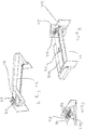
- FIG. 2a shows an enlargement of the upper portion of the cooling compartment 20.
- a recess 21 which is arranged in a slope 22.
- the slope 22 extends between one of the side walls 201 of the refrigerating compartment 20 and its ceiling 202.
- FIG. 2b shows the slope 22 in an enlarged view.
- the bevel 22 is a recess 21 for the arrangement of light sources 50.
- the light sources 50 are strip-like LEDs arranged.
- the slope 22 is also a recess 221 for the arrangement of the light guide 40th
- FIG. 3 shows a consideration of the FIG. 2a shown arrangement. Out FIG. 3 It follows how the slope 22 between the side wall 201 and the ceiling 202 of the cooling compartment 20 is arranged without the slope 22 protrudes into the insulating material 11 and that the slope 22 also has no influence on the not shown here winding of the freezer compartment evaporator.
- FIG. 4 shows the top of the refrigerator compartment according to FIG. 2 in an enlarged view, and a light panel 60.
- the light guide 40 is arranged in the light panel 60.
- the light panel 60 has beveled side walls 61 which cooperate with the slopes 22 when the light panel 60 is mounted.
- the panel 60 also has a plug connection 62, which cooperates with the recess 202 located in the ceiling 202 of the cooling compartment 20 and ensures a higher mechanical stability of the arrangement.
- FIG. 5 shows the light panel 60 in an assembled state.
- the chamfered side walls 61 of the light panel 60 cooperate with the slopes 22.
- FIG. 6a shows a bottom view of the arrangement according to FIG. 5 ,
- the light panel 60 is disposed on the slopes 22.
- the light comes from the light guide 40, which is arranged in the light panel 60.
- FIG. 6b shows a section of the FIG. 6a according to the section line AA. From this sectional view, the arrangement of the light guide 40 and the light panel 60 can be seen on the side facing the cooled interior of the refrigerating compartment 20 side of the ceiling 202 of the refrigerating compartment 20. The light light is not the insulation material 11, not shown here.
- FIG. 6c shows a section along the line BB in FIG. 6a ,
- the light conductor 40 is disposed in the panel 60.
- the chamfered sides 61 of the panel 60 cooperate with the slopes 22 so that the panel 60 is mechanically fixed to the structure.
- the panel 60 has a plug connection 62 which cooperates with the recess 23 in the ceiling 202 of the refrigerating compartment 20 in order to achieve a more stable attachment of the panel 60.
- FIGS. 7a and 7b show a light guide 40 in detail.
- the light guide 40 is fed by the light sources 50.
- the light sources are in line with the light pipe so that the light does not have to change direction.
- the light guide lies in a plane.
- the light beams from the light sources 50 are coupled into the light guide 40 and emitted from the light guide 40 into the cooling compartment 20 of the refrigerator 10 by means of light extraction areas 41 (light beams 51).
- the areas of the light extraction 41 can be defined by modifications of the light guide 40, such as coupling optics, imprints, matting, holograms or special plastics.
- the light-outcoupling regions 41 may be arranged arbitrarily in the light guide 40, so that propagation of the light into different regions and in multiple directions of the cooling compartment 20 is possible. However, it is particularly advantageous if the light is coupled out over the entire length of the light guide 40, so that a homogeneous and diffuse illumination of the cooling compartment 20 is achieved can.
- Different between the FIGS. 7a and 7b is the width of the area which serves to decouple the light: in the Figure 7a the extraction of light is only performed in the middle, while in the FIG. 7b the decoupling takes place over the entire length of the light guide.
Landscapes
- Engineering & Computer Science (AREA)
- Chemical & Material Sciences (AREA)
- Combustion & Propulsion (AREA)
- Physics & Mathematics (AREA)
- Mechanical Engineering (AREA)
- Thermal Sciences (AREA)
- General Engineering & Computer Science (AREA)
- Devices That Are Associated With Refrigeration Equipment (AREA)
Applications Claiming Priority (2)
| Application Number | Priority Date | Filing Date | Title |
|---|---|---|---|
| DE102017002505 | 2017-03-15 | ||
| DE102017110824.6A DE102017110824A1 (de) | 2017-03-15 | 2017-05-18 | Kühl- und/oder Gefriergerät |
Publications (1)
| Publication Number | Publication Date |
|---|---|
| EP3376145A1 true EP3376145A1 (fr) | 2018-09-19 |
Family
ID=61628182
Family Applications (1)
| Application Number | Title | Priority Date | Filing Date |
|---|---|---|---|
| EP18161425.6A Withdrawn EP3376145A1 (fr) | 2017-03-15 | 2018-03-13 | Appareil de réfrigération et/ou de congélation |
Country Status (1)
| Country | Link |
|---|---|
| EP (1) | EP3376145A1 (fr) |
Cited By (2)
| Publication number | Priority date | Publication date | Assignee | Title |
|---|---|---|---|---|
| DE102020213396A1 (de) | 2020-10-23 | 2022-04-28 | BSH Hausgeräte GmbH | Haushaltskältegerät mit einer Quertraverse und einem spezifisch daran befestigten Lichtmodul |
| DE102020213397A1 (de) | 2020-10-23 | 2022-04-28 | BSH Hausgeräte GmbH | Haushaltskältegerät mit Lichtmodul an Frontseite mit spezifischer Lichtabstrahlung schräg nach vorne und unten |
Citations (9)
| Publication number | Priority date | Publication date | Assignee | Title |
|---|---|---|---|---|
| US4706169A (en) * | 1986-12-08 | 1987-11-10 | Whirlpool Corporation | Lighting system for appliance dials |
| JPH0539978A (ja) * | 1991-08-02 | 1993-02-19 | Matsushita Electric Ind Co Ltd | 冷蔵庫 |
| JP2005344976A (ja) * | 2004-06-01 | 2005-12-15 | Toshiba Corp | 冷蔵庫 |
| KR100821710B1 (ko) * | 2007-01-10 | 2008-04-14 | 엘지전자 주식회사 | 냉장고용 조명장치 |
| DE102009002040A1 (de) * | 2009-03-31 | 2010-10-07 | BSH Bosch und Siemens Hausgeräte GmbH | Kombinations-Kältegerät mit Innenbeleuchtung |
| KR20120036667A (ko) * | 2010-10-08 | 2012-04-18 | 엘지이노텍 주식회사 | 자외선 엘이디가 구비된 냉장고 |
| JP2012255606A (ja) * | 2011-06-09 | 2012-12-27 | Toshiba Corp | 冷蔵庫 |
| JP5869787B2 (ja) * | 2011-07-04 | 2016-02-24 | シャープ株式会社 | 冷蔵庫 |
| DE102015003596A1 (de) * | 2014-10-10 | 2016-04-14 | Liebherr-Hausgeräte Lienz Gmbh | Kühl- und/oder Gefriergerät |
-
2018
- 2018-03-13 EP EP18161425.6A patent/EP3376145A1/fr not_active Withdrawn
Patent Citations (9)
| Publication number | Priority date | Publication date | Assignee | Title |
|---|---|---|---|---|
| US4706169A (en) * | 1986-12-08 | 1987-11-10 | Whirlpool Corporation | Lighting system for appliance dials |
| JPH0539978A (ja) * | 1991-08-02 | 1993-02-19 | Matsushita Electric Ind Co Ltd | 冷蔵庫 |
| JP2005344976A (ja) * | 2004-06-01 | 2005-12-15 | Toshiba Corp | 冷蔵庫 |
| KR100821710B1 (ko) * | 2007-01-10 | 2008-04-14 | 엘지전자 주식회사 | 냉장고용 조명장치 |
| DE102009002040A1 (de) * | 2009-03-31 | 2010-10-07 | BSH Bosch und Siemens Hausgeräte GmbH | Kombinations-Kältegerät mit Innenbeleuchtung |
| KR20120036667A (ko) * | 2010-10-08 | 2012-04-18 | 엘지이노텍 주식회사 | 자외선 엘이디가 구비된 냉장고 |
| JP2012255606A (ja) * | 2011-06-09 | 2012-12-27 | Toshiba Corp | 冷蔵庫 |
| JP5869787B2 (ja) * | 2011-07-04 | 2016-02-24 | シャープ株式会社 | 冷蔵庫 |
| DE102015003596A1 (de) * | 2014-10-10 | 2016-04-14 | Liebherr-Hausgeräte Lienz Gmbh | Kühl- und/oder Gefriergerät |
Cited By (2)
| Publication number | Priority date | Publication date | Assignee | Title |
|---|---|---|---|---|
| DE102020213396A1 (de) | 2020-10-23 | 2022-04-28 | BSH Hausgeräte GmbH | Haushaltskältegerät mit einer Quertraverse und einem spezifisch daran befestigten Lichtmodul |
| DE102020213397A1 (de) | 2020-10-23 | 2022-04-28 | BSH Hausgeräte GmbH | Haushaltskältegerät mit Lichtmodul an Frontseite mit spezifischer Lichtabstrahlung schräg nach vorne und unten |
Similar Documents
| Publication | Publication Date | Title |
|---|---|---|
| EP3376145A1 (fr) | Appareil de réfrigération et/ou de congélation | |
| DE2734614B2 (de) | Transportable Fernsprechvermittlungseinrichtung | |
| EP0200927A2 (fr) | Profilé de canal de câbles pour y poser des conduites d'installation ou similaires | |
| EP2594464A1 (fr) | Profil de liaison pour une structure de coffre d'un véhicule | |
| DE102005010219B3 (de) | Sammelschienen-Montagevorrichtung | |
| DE102017110824A1 (de) | Kühl- und/oder Gefriergerät | |
| DE69509447T2 (de) | Gerätechassis, insbesondere für ein elektrisches Gehäuse | |
| DE8226296U1 (de) | Kuehlgeraet, insbesondere kuehl- oder gefrierschrank | |
| DE102009009609A1 (de) | Leiterplatine und Trägerbauteil einer Beleuchtungsvorrichtung mit Leiterplatine | |
| DE102013015758A1 (de) | Batterie und Zellblock für eine Batterie | |
| DE102004049799B4 (de) | Zähler- und/oder Verteilervorrichtung | |
| EP2267384A2 (fr) | Liaison de porte | |
| DE102021105384A1 (de) | Beleuchtung für ein Kühl- und / oder Gefriergerät | |
| DD235769A1 (de) | Halterung fuer elektrische geraete in gerasteter einschubtechnik | |
| DE3305602C2 (de) | Montageelement für Kabelführungskanäle | |
| DE2912630A1 (de) | Gestell zur direkten aufnahme von elektronikeinschueben | |
| DE69304403T2 (de) | Kontinuierliche Verbindungen, insbesondere für Rahmen in elektrische Schränke oder dergleichen | |
| DE2630280A1 (de) | Schaltgeruest | |
| DE1784123C3 (de) | Vorrichtung zur Verbindung von rechtwinklig aneinander anschließenden Metallprofilstäben eines Traggerippes für Wandplatten | |
| DE7047743U (de) | Apparatedose fur Kabelfuhrungskanale | |
| DE2344808A1 (de) | Verdrahtungsrahmen fuer eine schalttafel | |
| DE102017111878A1 (de) | LED-Panel mit Basisplatte | |
| DE102020104927A1 (de) | Endkappe für die Kontaktierung eines Leuchtenmoduls, Leuchtenmodul und Leuchtensystem | |
| DE19602214A1 (de) | Elektrisches Unterputz-Installationseinbaugerät | |
| DE2222623C3 (de) | Gehäuse für eine mit Leuchtstoffröhrenlampen versehene Deckenleuchte |
Legal Events
| Date | Code | Title | Description |
|---|---|---|---|
| PUAI | Public reference made under article 153(3) epc to a published international application that has entered the european phase |
Free format text: ORIGINAL CODE: 0009012 |
|
| STAA | Information on the status of an ep patent application or granted ep patent |
Free format text: STATUS: THE APPLICATION HAS BEEN PUBLISHED |
|
| AK | Designated contracting states |
Kind code of ref document: A1 Designated state(s): AL AT BE BG CH CY CZ DE DK EE ES FI FR GB GR HR HU IE IS IT LI LT LU LV MC MK MT NL NO PL PT RO RS SE SI SK SM TR |
|
| AX | Request for extension of the european patent |
Extension state: BA ME |
|
| STAA | Information on the status of an ep patent application or granted ep patent |
Free format text: STATUS: REQUEST FOR EXAMINATION WAS MADE |
|
| 17P | Request for examination filed |
Effective date: 20190318 |
|
| STAA | Information on the status of an ep patent application or granted ep patent |
Free format text: STATUS: EXAMINATION IS IN PROGRESS |
|
| 17Q | First examination report despatched |
Effective date: 20191023 |
|
| STAA | Information on the status of an ep patent application or granted ep patent |
Free format text: STATUS: THE APPLICATION IS DEEMED TO BE WITHDRAWN |
|
| 18D | Application deemed to be withdrawn |
Effective date: 20211001 |