EP0200927A2 - Profilé de canal de câbles pour y poser des conduites d'installation ou similaires - Google Patents
Profilé de canal de câbles pour y poser des conduites d'installation ou similaires Download PDFInfo
- Publication number
- EP0200927A2 EP0200927A2 EP86104623A EP86104623A EP0200927A2 EP 0200927 A2 EP0200927 A2 EP 0200927A2 EP 86104623 A EP86104623 A EP 86104623A EP 86104623 A EP86104623 A EP 86104623A EP 0200927 A2 EP0200927 A2 EP 0200927A2
- Authority
- EP
- European Patent Office
- Prior art keywords
- channel
- cable duct
- profile
- walls
- cover
- Prior art date
- Legal status (The legal status is an assumption and is not a legal conclusion. Google has not performed a legal analysis and makes no representation as to the accuracy of the status listed.)
- Granted
Links
Images

Classifications
-
- H—ELECTRICITY
- H02—GENERATION; CONVERSION OR DISTRIBUTION OF ELECTRIC POWER
- H02G—INSTALLATION OF ELECTRIC CABLES OR LINES, OR OF COMBINED OPTICAL AND ELECTRIC CABLES OR LINES
- H02G3/00—Installations of electric cables or lines or protective tubing therefor in or on buildings, equivalent structures or vehicles
- H02G3/02—Details
- H02G3/04—Protective tubing or conduits, e.g. cable ladders or cable troughs
- H02G3/0437—Channels
-
- H—ELECTRICITY
- H02—GENERATION; CONVERSION OR DISTRIBUTION OF ELECTRIC POWER
- H02G—INSTALLATION OF ELECTRIC CABLES OR LINES, OR OF COMBINED OPTICAL AND ELECTRIC CABLES OR LINES
- H02G3/00—Installations of electric cables or lines or protective tubing therefor in or on buildings, equivalent structures or vehicles
- H02G3/02—Details
- H02G3/04—Protective tubing or conduits, e.g. cable ladders or cable troughs
- H02G3/0406—Details thereof
- H02G3/0418—Covers or lids; Their fastenings
Definitions
- the invention relates to a cable duct profile for laying installation lines or the like.
- a U-shaped duct body With a U-shaped duct body, the installation opening formed by the duct walls is closed by a cover, which is attached in particular to the ends of the duct walls on the outside.
- the invention is based on the object of improving a cable duct profile of the type mentioned at the outset in such a way that it can be manufactured with different cross sections, with partial reuse of its components, so that correspondingly larger or smaller quantities of installation lines can be laid inside .
- the channel walls and the bottom of the channel body are detachably connected to one another and can be exchanged for walls and / or floors of different dimensions. It is important for the invention that the channel walls are interchangeable. Duct walls and floors of other dimensions can be used and a cable duct profile with a different cross section can be produced with it.
- the channel walls and the floor are connected via snap-in connections. After loosening the locking connections by means of advantageous swiveling or sliding movements transverse to the longitudinal axis of the profile, the parts can be exchanged. It is conceivable to use sliding connections instead of the latching connections, so that the parts to be assembled are assembled in their longitudinal direction by pushing one into the other.
- such a design of the connection points has several disadvantages, above all the double assembly length required for assembly, but also the movement resistance due to warping of the parts transversely to their longitudinal direction.
- the bottom of the channel body and / or its cover have on their outer edges in the direction of the channel walls abutment strips, which are engaged by hook strips projecting into the channel interior.
- the latching is therefore advantageously carried out at the edges or in the corner region of the profile.
- the hook strips of a snap-in connection of a duct wall have a pressure web, which can be snapped into a snap-in recess when the cooperating hook and abutment strips are caught while overcoming a snap-in bar.
- Such locking connections ensure a secure cohesion of the components to be locked, that is, in particular the floor with walls, but also the cover, the locking connection being designed such that it connects the associated channel wall in the sense of bracing another locking connection or another releasable connection of a channel part is able to preload with another duct part.
- the hook and abutment strips have a ball joint-like cross section.
- the abutment strips of the bottom and the cover as well as the hook strips of the channel walls are each designed identically in their engagement area.
- the locking connections of the floor and the Lids are interchanged or the channel walls are to be arranged rotated by 180 ° in their plane.
- the latching connections of a channel wall are designed differently or if only one latching connection is present on a channel wall, which has a pressure web and thus prestresses the channel wall, this can optionally be used on the cover of the cable channel profile.
- the bottom and the cover of the channel for each snap connection have a snap bar support projecting into the channel interior, each with a snap recess and a snap bar.
- the latching web supports of the floor are connected to one another in a supporting manner with a connecting web, if necessary having actuating openings, and in the floor a longitudinally running fastening slot opening into a fastening groove enclosed by the gutter profile is arranged.
- the channel profile enables the arrangement of an uninterrupted longitudinal fastening slot with which the cable duct profile can be attached to the supporting surface in a stepless manner.
- the base has at least two channel profiles arranged next to one another, between which two abutment strips are arranged which are matched to their latching web supports. Both channel profiles allow the above-described fastening of the cable duct profile.
- the interior of the channel is divided by an intermediate wall, which is detachably connected to the floor via a snap connection. That is for example required to separate high-voltage and low-voltage installation lines.
- the intermediate wall and the channel walls are of identical design, which facilitates the manufacture and storage of intermediate walls.
- the bottom of the duct body has a cross-section of the cover, or the cover has a cross-section of the base if this is required for special purposes.
- the interchangeability of the cover and base is advantageously used in such a way that a cover cross-section instead of a base cross-section is present in the longitudinal direction of the cable duct profile.
- a cover piece could therefore take the place of a base piece, for example if there is no fastening possibility and a simple and therefore cheaper profile is sufficient, or if outlet openings are to be produced with a simple cover profile.
- separate duct wall section is provided to be able to, for example, to slightly expand a threaded through the side outlet openings harness, 'without having to remove the channel wall as a whole.
- this goal is achieved in that the cable duct profile is slotted at intervals over its entire length, so that the individual tabs which are created can be broken out at the desired location.
- slitting is a time-consuming manufacturing process and the slits reduce the duct wall stiffness. Both can be avoided by using the aforementioned duct wall sections.
- the cross-sectional lengths of K are portable channel profile with a grid measured in a ratio of 1: 1 or an integer multiple.
- the cable duct Profile releasably connected to a hollow profile rod, the cross-sectional lengths of which are matched to those of the cable duct and which has at least one fastening duct arranged congruently with the fastening slot of the cable duct for receiving a connecting part.
- the cable duct profile is provided with a support with which it can be freely laid, particularly over longer lengths, in the absence of other fastening options.
- the attachment of the cable duct profile to frames that are constructed from such hollow profile rods is also possible without any problems and facilitates e.g. the production of work tables using such hollow profile bars and cable duct profiles.
- the cable duct profile can also be laid across or at any angle to the hollow profile rod and attached to it.
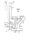
- the cable duct profile 10 of FIG. 1 which is expediently made of a light metal alloy for reasons of strength, has a base 14, two walls 13 attached to it and a cover 12 which enclose the interior 18 of the cable duct profile 10, in which e.g. electrical installation lines are laid.
- the base 14 and the channel walls 13 are assembled with latching connections 15 to form a channel body 11 which has a wide installation opening 18a between the ends 39 of the channel walls 13.
- the channel wall 13 has an L-shaped hook strip 20 which projects into the channel interior 18 and runs parallel to the wall 13 with its long L-leg.
- This L-leg or the hook strip 20 engages behind an abutment strip 19 present on the outer edge 17 of the base 14, which protrudes from the base 14 in the direction of the channel wall 13 and is flush with it.
- the abutment strip 19 has a bead 19a on the wall side, which has a circular cross-section in its area touching the hook strip 20. Accordingly, the hook strip 20 is also circularly profiled in its area of contact with the abutment strip 19.
- the hook strip 20 has at its bottom end a rib 20a projecting towards the abutment bar 19, with which the bead 19a is engaged.
- the cross section of the hook bar 20 and the abutment bar 19 in the contact area of both is ball-joint-like.
- the locking web carrier 24 is designed and arranged such that the pressure web 21 is firmly seated in the locking recess 23 and is held therein.
- the locking web carrier 24 is integrally connected to the bottom 14.
- the locking connection 15 is assembled in such a way that the wall 13 is initially arranged in the dot-dash position in which the hook strip 20 is seated on the bead 19a in such a way that the pressure web 21 abuts the locking web 22. Then the wall 13 is pivoted further in the direction of the arrow 13a and by overcoming the latching web 22 until the wall 13 assumes its position shown with a solid line. This position can be blocked in that an approximately a-strong screw is arranged between the hook bar 20 and the part 24a of the locking web carrier 24, which screw is screwed through a hole made with the aid of a drilling auxiliary groove 37 in the bottom 14. This is the drilling auxiliary groove 37 is arranged in the projection between the hook strip 20 and the locking web carrier 24.
- the dashed position 13b of the channel wall 13 indicates that the channel wall 13 is biased outwards by the latching connection 15, unless the cover 12 shown in FIG. 1 is placed on the two channel walls 13. This pulls the prestressed channel walls 13 into the position shown in FIG. 1, shown with solid lines.
- the cover 12 sits by means of. the locking connections 16 on the ends 39 of the channel walls 13 can therefore only be removed again by releasing the locking connections 16.
- a pressure web designed according to the latching connection 15 is not necessary in the region of these latching connections. Rather, it is sufficient that the hook and the abutment strips 19, 20 are designed in the same way as those of the latching connection 15.
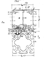
- Fig. 3 shows a K abelkarnalprofil 10a, whose cross-section length Q w of the walls 13 and Q bd the bottom 14 and the cover 12 are twice as large as the corresponding cross-sectional lengths according to Fig. 1.
- the snap-in connections 15, 16 are of the same configuration and dimensioned, as well as the adjacently arranged locking web carriers 24.
- the cover 12 has only two of these locking web carriers.
- the floor 14, on the other hand, has four locking web supports 24, two of which are each arranged in mirror image and are connected to each other to form a channel profile 27 by a connecting web 26.
- Each channel profile 27 encloses a fastening groove 28 which is accessible from the outside through a fastening slot 29.
- a connecting part 36 designed as a screw is arranged with a screw head 36a in the fastening groove 28, while the screw shaft 36b of the connecting part 36 accommodates the loading fastening slot 29 protrudes.
- the screw shaft 36b is screwed into the threaded bore of a clamping piece 38, so that the hollow profile rod 34 and the base 14 are drawn together.
- the clamping piece 38 is a prismatic body that extends perpendicular to the plane of the representation and has approximately the shape of a circular segment.
- the cross section is matched to the width of the fastening slot 29 in such a way that the clamping piece 38 can be brought into the position shown in FIG.
- the connecting part 36 is pushed with the screw head 36a from one end of the fastening groove 28 to an actuation opening 25 in the connecting web 26. Through the actuating opening 25, for example, an Allen key is inserted and the connecting part 36 is screwed into the clamping piece 38. Since two parallel channel trough profiles 27 are present in the cable duct profile 10a, this attachment can also be carried out twice.
- Both channel profiles 27 have terminal fastening strips 31 projecting towards the interior 18, on which installation clamps can be fixed, which are pushed onto these strips 31 in the direction perpendicular to the plane of illustration.
- the strips 31 are L-shaped and arranged opposite one another, so that, in the absence of the intermediate wall 30 shown in FIG. 3, it is also possible to use standard installation clamps which overlap the two strips 31 in a C-shape.
- the intermediate wall 30 is profiled like a channel wall 13, so that it can form a latching connection 15 according to FIG. 3 and, as can be seen in FIG. 3, divides the interior space 18.
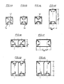
- the cable duct profile can be constructed from modularly designed components.
- the cross-sectional lengths Q bd , Q w according to FIG. 1 are each equal to a grid dimension r, that is to say in a ratio of 1: 1.
- the profiles of FIGS. 4e, f are wide, but are flat according to FIGS. 4a to 4c. 4g, h are designed in accordance with the profile of FIG.
- the profile of the F ig. 4a has a bottom 14 with a channel profile 27 for attachment to the hollow bar profile 34 of FIG. 3 or a similar profile.
- the cover 12, however, is designed according to FIG. 1.
- the profile of FIG. 4b corresponds to that of FIG. 1, that is to say it has a base part 14 with a cross section of the cover.
- the profile of FIG. 4c has a cover 12 with a bottom cross section.
- the profile of Fig. 4d corresponds to to its double cross-sectional length Q w the profile of FIG. 4a, while the profile of FIG. 4f corresponds to the profile of FIG. 4b up to its double cross-sectional length Q bd .
- the eight cable duct profiles illustrated by FIGS. 4a to 4h can be produced with a total of only six differently profiled parts, which illustrates the universality of the profile system.
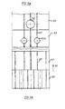
- FIG. 5a shows in view a of FIG. 3 that wall sections 33 of the channel wall 13 which are configured differently in sections in the longitudinal direction and which, for example, have a side outlet opening 32 or two ventilation openings 32a. If such a channel wall section 33 is no longer required, it can be removed and replaced by a desired replacement section.
- FIG. 5b shows in view b of FIG. 3 in the longitudinal direction 42 a duct wall section 40 with a bottom cross section according to FIG. 3 and then a duct section 41 with a cover cross section, five drilling auxiliary grooves 37 being present, as can be seen from view b 'according to FIG. 3 results.
- the hollow profile rods 34 to which the cable duct profiles 10 are attached, also have correspondingly dimensioned cross members have cut lengths, as can be seen from FIG. 3. From this figure it can be seen that the two cross-sections in question each have the same cross-sectional lengths.
Landscapes
- Engineering & Computer Science (AREA)
- Architecture (AREA)
- Civil Engineering (AREA)
- Structural Engineering (AREA)
- Details Of Indoor Wiring (AREA)
- Laying Of Electric Cables Or Lines Outside (AREA)
- Electric Cable Installation (AREA)
- Suspension Of Electric Lines Or Cables (AREA)
Priority Applications (1)
| Application Number | Priority Date | Filing Date | Title |
|---|---|---|---|
| AT86104623T ATE61165T1 (de) | 1985-05-04 | 1986-04-04 | Kabelkanalprofil zur verlegung von installationsleitungen od. dgl. |
Applications Claiming Priority (2)
| Application Number | Priority Date | Filing Date | Title |
|---|---|---|---|
| DE19853516149 DE3516149A1 (de) | 1985-05-04 | 1985-05-04 | Kabelkanalprofil zur verlegung von installationsleitungen od. dgl. |
| DE3516149 | 1985-05-04 |
Publications (3)
| Publication Number | Publication Date |
|---|---|
| EP0200927A2 true EP0200927A2 (fr) | 1986-11-12 |
| EP0200927A3 EP0200927A3 (en) | 1989-01-25 |
| EP0200927B1 EP0200927B1 (fr) | 1991-02-27 |
Family
ID=6269892
Family Applications (1)
| Application Number | Title | Priority Date | Filing Date |
|---|---|---|---|
| EP86104623A Expired - Lifetime EP0200927B1 (fr) | 1985-05-04 | 1986-04-04 | Profilé de canal de câbles pour y poser des conduites d'installation ou similaires |
Country Status (3)
| Country | Link |
|---|---|
| EP (1) | EP0200927B1 (fr) |
| AT (1) | ATE61165T1 (fr) |
| DE (2) | DE3516149A1 (fr) |
Cited By (9)
| Publication number | Priority date | Publication date | Assignee | Title |
|---|---|---|---|---|
| EP0389382A1 (fr) * | 1989-03-24 | 1990-09-26 | Ingenierie Boga | Gaine pour canalisation profilé pour sa réalisation et procédé de montage d'une telle gaine |
| EP0562499A1 (fr) * | 1992-03-24 | 1993-09-29 | del Vesco, Heinz | Profilé pour canalisation de câbles |
| EP0654878A1 (fr) * | 1993-11-24 | 1995-05-24 | Bocchiotti Societa'per L'industria Elettrotecnica S.P.A. | Canalisation de maintien de câble électrique etc. avec couvercle ne pouvant être enlevé qu'avec des outils |
| WO1997011516A1 (fr) * | 1995-09-19 | 1997-03-27 | Andreas Hierzer | Rail porteur pour luminaires |
| WO1997050161A1 (fr) * | 1996-06-24 | 1997-12-31 | Hilti Aktiengesellschaft | Profile pour le passage de cables |
| EP0767521A3 (fr) * | 1995-10-03 | 1998-07-22 | Smc Corporation | Conduit multifonctionnel |
| EP0863594A3 (fr) * | 1997-03-06 | 2000-01-05 | Albert Ackermann GmbH & Co. KG | Canalisation pour installation électrique |
| EP3595106A1 (fr) * | 2018-07-10 | 2020-01-15 | Robert Bosch GmbH | Conduit de câble |
| EP3240129B1 (fr) * | 2016-04-27 | 2023-12-20 | arc2lab GmbH | Système d'alimentation |
Families Citing this family (4)
| Publication number | Priority date | Publication date | Assignee | Title |
|---|---|---|---|---|
| DE4017330C1 (fr) * | 1990-05-30 | 1991-11-07 | Dorma Gmbh + Co. Kg, 5828 Ennepetal, De | |
| DE19532392C2 (de) * | 1995-09-02 | 2003-07-03 | Bosch Gmbh Robert | Kabelkanalprofil zur Verlegung von Installationsleitungen oder dergleichen |
| DE102014005548B4 (de) | 2014-04-16 | 2017-04-06 | Detlef Wittkopp | Kabelkanalsystem |
| DE102015000289B4 (de) | 2015-01-17 | 2017-10-12 | Detlef Wittkopp | Kabelkanalsystem |
Family Cites Families (2)
| Publication number | Priority date | Publication date | Assignee | Title |
|---|---|---|---|---|
| DE1236621B (de) * | 1962-07-19 | 1967-03-16 | Albert Theysohn | Bauelementensatz fuer die Zusammenstellung von Kabelfuehrungskanaelen |
| US3761603A (en) * | 1972-11-14 | 1973-09-25 | Amp Inc | Wiring raceway |
-
1985
- 1985-05-04 DE DE19853516149 patent/DE3516149A1/de not_active Withdrawn
-
1986
- 1986-04-04 EP EP86104623A patent/EP0200927B1/fr not_active Expired - Lifetime
- 1986-04-04 AT AT86104623T patent/ATE61165T1/de not_active IP Right Cessation
- 1986-04-04 DE DE8686104623T patent/DE3677630D1/de not_active Expired - Fee Related
Cited By (12)
| Publication number | Priority date | Publication date | Assignee | Title |
|---|---|---|---|---|
| EP0389382A1 (fr) * | 1989-03-24 | 1990-09-26 | Ingenierie Boga | Gaine pour canalisation profilé pour sa réalisation et procédé de montage d'une telle gaine |
| FR2644946A1 (fr) * | 1989-03-24 | 1990-09-28 | Rotoclip Sa | Gaine pour canalisation, profile pour sa realisation et procede de montage d'une telle gaine |
| EP0562499A1 (fr) * | 1992-03-24 | 1993-09-29 | del Vesco, Heinz | Profilé pour canalisation de câbles |
| DE4209499A1 (de) * | 1992-03-24 | 1993-09-30 | Giovanni Miranda | Kabelkanalprofil |
| EP0654878A1 (fr) * | 1993-11-24 | 1995-05-24 | Bocchiotti Societa'per L'industria Elettrotecnica S.P.A. | Canalisation de maintien de câble électrique etc. avec couvercle ne pouvant être enlevé qu'avec des outils |
| WO1997011516A1 (fr) * | 1995-09-19 | 1997-03-27 | Andreas Hierzer | Rail porteur pour luminaires |
| EP0767521A3 (fr) * | 1995-10-03 | 1998-07-22 | Smc Corporation | Conduit multifonctionnel |
| US5949025A (en) * | 1995-10-03 | 1999-09-07 | Smc Corporation | Multifunctional conduit |
| WO1997050161A1 (fr) * | 1996-06-24 | 1997-12-31 | Hilti Aktiengesellschaft | Profile pour le passage de cables |
| EP0863594A3 (fr) * | 1997-03-06 | 2000-01-05 | Albert Ackermann GmbH & Co. KG | Canalisation pour installation électrique |
| EP3240129B1 (fr) * | 2016-04-27 | 2023-12-20 | arc2lab GmbH | Système d'alimentation |
| EP3595106A1 (fr) * | 2018-07-10 | 2020-01-15 | Robert Bosch GmbH | Conduit de câble |
Also Published As
| Publication number | Publication date |
|---|---|
| DE3677630D1 (de) | 1991-04-04 |
| ATE61165T1 (de) | 1991-03-15 |
| DE3516149A1 (de) | 1986-11-06 |
| EP0200927B1 (fr) | 1991-02-27 |
| EP0200927A3 (en) | 1989-01-25 |
Similar Documents
| Publication | Publication Date | Title |
|---|---|---|
| EP0404284B1 (fr) | Charpente pour une cabine de distribution à éléments profilés coudés plusieurs fois | |
| DE69100778T2 (de) | Raumaufteilungssystem für Büros. | |
| EP0331690B1 (fr) | Revetement pour plafonds | |
| EP0200927B1 (fr) | Profilé de canal de câbles pour y poser des conduites d'installation ou similaires | |
| DE69409371T2 (de) | Fassadenverkleidung | |
| DE2356225C3 (fr) | ||
| EP0325985A1 (fr) | Faux plafond à profilés suspendus | |
| DE69623870T2 (de) | Leicht transportierbare und zusammensetzbare Wandstruktur mit Schiebetür | |
| DE2504476A1 (de) | Beschlag fuer die befestigung eines profiltraegers zur bildung eines rahmens | |
| DE3604585C2 (de) | Befestigungsvorrichtung für eine Fassadenverkleidung | |
| AT15184U1 (de) | Lichtbandsystem mit länglicher Tragschiene | |
| WO2000040874A1 (fr) | Canal de guidage | |
| DE19508949C2 (de) | Bausatz für ein Tragsystem | |
| DE1962889C3 (de) | Wand- oder Deckenbekleidung mit Lamellen | |
| DE2850779A1 (de) | Zarge, die mit elektrischen kabelkanaelen so zusammenarbeitet, dass die leiter eine wandoeffnung umgehen koennen, ohne arbeiten an der wand zu erfordern | |
| EP0959536B1 (fr) | Bloc multiprises | |
| DE2923903A1 (de) | Wandbefestigungselement fuer plattenheizkoerper | |
| DE9306657U1 (de) | Hängefördereinrichtung mit einem Montageprofilsatz | |
| DE19614942B4 (de) | Profilverbindung für unter Gehrung zusammenstoßende Profile | |
| DE20100753U1 (de) | Befestigungsanordnung für Lamellenregister | |
| DE9304726U1 (de) | Gerüstkonstruktion | |
| DE69206475T2 (de) | Bodenrahmen für elektrischen Kasten. | |
| DE9404101U1 (de) | Befestigungsteil zur Befestigung von Flächenelementen an Profilstäben | |
| DE29503377U1 (de) | Profilleisten-Modulsystem | |
| DE3206865C2 (de) | Vorhangschienenträgeranordnung |
Legal Events
| Date | Code | Title | Description |
|---|---|---|---|
| PUAI | Public reference made under article 153(3) epc to a published international application that has entered the european phase |
Free format text: ORIGINAL CODE: 0009012 |
|
| AK | Designated contracting states |
Kind code of ref document: A2 Designated state(s): AT BE CH DE FR GB IT LI LU NL SE |
|
| PUAL | Search report despatched |
Free format text: ORIGINAL CODE: 0009013 |
|
| AK | Designated contracting states |
Kind code of ref document: A3 Designated state(s): AT BE CH DE FR GB IT LI LU NL SE |
|
| 17P | Request for examination filed |
Effective date: 19890306 |
|
| 17Q | First examination report despatched |
Effective date: 19891218 |
|
| GRAA | (expected) grant |
Free format text: ORIGINAL CODE: 0009210 |
|
| AK | Designated contracting states |
Kind code of ref document: B1 Designated state(s): AT BE CH DE FR GB IT LI LU NL SE |
|
| REF | Corresponds to: |
Ref document number: 61165 Country of ref document: AT Date of ref document: 19910315 Kind code of ref document: T |
|
| GBT | Gb: translation of ep patent filed (gb section 77(6)(a)/1977) | ||
| REF | Corresponds to: |
Ref document number: 3677630 Country of ref document: DE Date of ref document: 19910404 |
|
| ET | Fr: translation filed | ||
| ITF | It: translation for a ep patent filed | ||
| PLBE | No opposition filed within time limit |
Free format text: ORIGINAL CODE: 0009261 |
|
| STAA | Information on the status of an ep patent application or granted ep patent |
Free format text: STATUS: NO OPPOSITION FILED WITHIN TIME LIMIT |
|
| 26N | No opposition filed | ||
| EPTA | Lu: last paid annual fee | ||
| EAL | Se: european patent in force in sweden |
Ref document number: 86104623.3 |
|
| NLS | Nl: assignments of ep-patents |
Owner name: DIPL.-ING. WOLFGANG RIXEN;GERRIT PIES |
|
| REG | Reference to a national code |
Ref country code: FR Ref legal event code: RM |
|
| REG | Reference to a national code |
Ref country code: FR Ref legal event code: TP |
|
| REG | Reference to a national code |
Ref country code: GB Ref legal event code: 713H Ref country code: GB Ref legal event code: 713D |
|
| REG | Reference to a national code |
Ref country code: GB Ref legal event code: 732E |
|
| BECA | Be: change of holder's address |
Free format text: 980429 WOLFGANG *RIXEN;GERRIT *PIES:SPATENWEG 11, D-42655 SOLINGEN; LINDENBAUMSTRASSE 4 D-42659 SOLINGEN |
|
| REG | Reference to a national code |
Ref country code: GB Ref legal event code: IF02 |
|
| PGFP | Annual fee paid to national office [announced via postgrant information from national office to epo] |
Ref country code: NL Payment date: 20040331 Year of fee payment: 19 Ref country code: GB Payment date: 20040331 Year of fee payment: 19 |
|
| PGFP | Annual fee paid to national office [announced via postgrant information from national office to epo] |
Ref country code: SE Payment date: 20040402 Year of fee payment: 19 Ref country code: LU Payment date: 20040402 Year of fee payment: 19 Ref country code: CH Payment date: 20040402 Year of fee payment: 19 |
|
| PGFP | Annual fee paid to national office [announced via postgrant information from national office to epo] |
Ref country code: AT Payment date: 20040405 Year of fee payment: 19 |
|
| PGFP | Annual fee paid to national office [announced via postgrant information from national office to epo] |
Ref country code: FR Payment date: 20040415 Year of fee payment: 19 |
|
| PGFP | Annual fee paid to national office [announced via postgrant information from national office to epo] |
Ref country code: BE Payment date: 20040527 Year of fee payment: 19 |
|
| PGFP | Annual fee paid to national office [announced via postgrant information from national office to epo] |
Ref country code: DE Payment date: 20040628 Year of fee payment: 19 |
|
| PG25 | Lapsed in a contracting state [announced via postgrant information from national office to epo] |
Ref country code: LU Free format text: LAPSE BECAUSE OF NON-PAYMENT OF DUE FEES Effective date: 20050404 Ref country code: IT Free format text: LAPSE BECAUSE OF NON-PAYMENT OF DUE FEES;WARNING: LAPSES OF ITALIAN PATENTS WITH EFFECTIVE DATE BEFORE 2007 MAY HAVE OCCURRED AT ANY TIME BEFORE 2007. THE CORRECT EFFECTIVE DATE MAY BE DIFFERENT FROM THE ONE RECORDED. Effective date: 20050404 Ref country code: GB Free format text: LAPSE BECAUSE OF NON-PAYMENT OF DUE FEES Effective date: 20050404 Ref country code: AT Free format text: LAPSE BECAUSE OF NON-PAYMENT OF DUE FEES Effective date: 20050404 |
|
| PG25 | Lapsed in a contracting state [announced via postgrant information from national office to epo] |
Ref country code: SE Free format text: LAPSE BECAUSE OF NON-PAYMENT OF DUE FEES Effective date: 20050405 |
|
| PG25 | Lapsed in a contracting state [announced via postgrant information from national office to epo] |
Ref country code: LI Free format text: LAPSE BECAUSE OF NON-PAYMENT OF DUE FEES Effective date: 20050430 Ref country code: CH Free format text: LAPSE BECAUSE OF NON-PAYMENT OF DUE FEES Effective date: 20050430 Ref country code: BE Free format text: LAPSE BECAUSE OF NON-PAYMENT OF DUE FEES Effective date: 20050430 |
|
| BERE | Be: lapsed |
Owner name: GERRIT *PIES Effective date: 20050430 Owner name: WOLFGANG *RIXEN Effective date: 20050430 |
|
| PG25 | Lapsed in a contracting state [announced via postgrant information from national office to epo] |
Ref country code: NL Free format text: LAPSE BECAUSE OF NON-PAYMENT OF DUE FEES Effective date: 20051101 Ref country code: DE Free format text: LAPSE BECAUSE OF NON-PAYMENT OF DUE FEES Effective date: 20051101 |
|
| EUG | Se: european patent has lapsed | ||
| REG | Reference to a national code |
Ref country code: CH Ref legal event code: PL |
|
| GBPC | Gb: european patent ceased through non-payment of renewal fee |
Effective date: 20050404 |
|
| PG25 | Lapsed in a contracting state [announced via postgrant information from national office to epo] |
Ref country code: FR Free format text: LAPSE BECAUSE OF NON-PAYMENT OF DUE FEES Effective date: 20051230 |
|
| NLV4 | Nl: lapsed or anulled due to non-payment of the annual fee |
Effective date: 20051101 |
|
| REG | Reference to a national code |
Ref country code: FR Ref legal event code: ST Effective date: 20051230 |
|
| BERE | Be: lapsed |
Owner name: GERRIT *PIES Effective date: 20050430 Owner name: WOLFGANG *RIXEN Effective date: 20050430 |