EP3376151A1 - Verschluss für schusswaffen - Google Patents
Verschluss für schusswaffen Download PDFInfo
- Publication number
- EP3376151A1 EP3376151A1 EP17161425.8A EP17161425A EP3376151A1 EP 3376151 A1 EP3376151 A1 EP 3376151A1 EP 17161425 A EP17161425 A EP 17161425A EP 3376151 A1 EP3376151 A1 EP 3376151A1
- Authority
- EP
- European Patent Office
- Prior art keywords
- chamber
- lever
- control piece
- closure
- piece
- Prior art date
- Legal status (The legal status is an assumption and is not a legal conclusion. Google has not performed a legal analysis and makes no representation as to the accuracy of the status listed.)
- Granted
Links
Images


Classifications
-
- F—MECHANICAL ENGINEERING; LIGHTING; HEATING; WEAPONS; BLASTING
- F41—WEAPONS
- F41A—FUNCTIONAL FEATURES OR DETAILS COMMON TO BOTH SMALLARMS AND ORDNANCE, e.g. CANNONS; MOUNTINGS FOR SMALLARMS OR ORDNANCE
- F41A3/00—Breech mechanisms, e.g. locks
- F41A3/12—Bolt action, i.e. the main breech opening movement being parallel to the barrel axis
- F41A3/14—Rigid bolt locks, i.e. having locking elements rigidly mounted on the bolt or bolt handle and on the barrel or breech-housing respectively
- F41A3/16—Rigid bolt locks, i.e. having locking elements rigidly mounted on the bolt or bolt handle and on the barrel or breech-housing respectively the locking elements effecting a rotary movement about the barrel axis, e.g. rotating cylinder bolt locks
- F41A3/18—Rigid bolt locks, i.e. having locking elements rigidly mounted on the bolt or bolt handle and on the barrel or breech-housing respectively the locking elements effecting a rotary movement about the barrel axis, e.g. rotating cylinder bolt locks hand-operated
- F41A3/20—Straight-pull operated bolt locks, i.e. the operating hand effecting only a straight movement parallel to the barrel axis
Definitions
- the present invention relates to a closure device for firearms, in particular for repeating rifles, comprising a cartridge chamber, an outer sleeve and a chamber accommodated therein, the chamber having a closure head in the region facing the cartridge chamber and within the chamber a control piece relative to the chamber and opposite the lock head is axially displaceably mounted, further comprising a chamber lever, which is connected to the control piece, so that upon a backward movement of the chamber lever, the lock head is unlocked and locked in the course, the chamber lever is pivotally mounted in the rear end of the sleeve and the chamber lever to an axis is pivotally mounted, which extends eccentrically to the longitudinal axis of the chamber.
- a closure device for firearms in particular for repeating rifles, known with a cartridge chamber, with an outer sleeve and a chamber accommodated therein, wherein the chamber in the chamber facing the cartridge chamber has a closure head and within the chamber a control piece is mounted, so that at the backward movement of the chamber lever, the lock head unlocked and locked in the course.
- the closure head is not rotatably mounted.
- the locking is done by means of locking elements in the form of balls, which are pressed over a bevelled front end face of the control piece during its advancement to the outside of the inner wall of the closure sleeve.
- the chamber lever has a favorable rear position in this weapon, but the lock on said balls has proved in practice to be disadvantageous.
- a straight-pull closure for a firearm in which the closure head is mounted rotatably in a chamber about its own axis and fixed by a shoulder opposite the chamber in its axial movement.
- a control sleeve has at its front a control pin whose surface is in contact with a control groove.
- the bolt handle is by design at the front end of it closure. This front position of the chamber handle makes handling and a fast weapon function difficult.
- the object of the present invention is to provide a closure, in particular a straight-pull closure, for a firearm with the features of the type mentioned above, which ensures a secure locking via a rotatable closure head with a simple construction and tool-free dismantling.
- control piece is connected via an intermediate piece with the chamber lever, which protrudes from the chamber radially outwardly that the closure head is rotatably mounted about its axis in the chamber and the closure head is rotated by axial displacement of the control piece.
- the control piece is connected via an intermediate piece with the chamber lever. Because the axis about which the chamber lever pivots eccentrically (relative to the longitudinal axis of the chamber) is arranged and the intermediate piece, on which the chamber lever engages, can be attached to the pivot axis of the chamber lever opposite side of the weapon while still lying radially outward, is also the point of application of the chamber lever to the Intermediate piece in a comparatively large distance from the pivot axis of the chamber lever, which in turn has the consequence that during the pivotal movement of the chamber lever, a large longitudinal stroke of the intermediate piece and thus of the control piece is achieved. This comparatively large longitudinal stroke of the control piece is then converted into a rotary movement of the closure head with a correspondingly large angle of rotation, whereby a secure locking of the closure head is achieved.
- the intermediate piece is guided displaceably in the longitudinal direction in at least one groove or recess in the wall of the sleeve.
- this results in an additional guide for the intermediate piece in the sleeve and the intermediate piece can be arranged so far radially outward that it extends not only beyond the chamber in the radial direction, but at least partially beyond the sleeve outwards.
- the intermediate piece is also displaceably guided in an elongated hole of the chamber in the longitudinal direction.
- a hinged connection of the chamber lever is provided with the intermediate piece via an axle, the axis of which is parallel to the axis about which the chamber lever is pivotally mounted, wherein the axle in the plan view is arranged radially out of alignment of the chamber ,
- the axle member thus has a comparatively large distance (in the transverse direction of the weapon) to the pivot axis of the chamber lever, whereby upon actuation of the chamber lever, a long pivoting path and thus a large distance results, which traverses the intermediate piece upon retraction of the chamber lever. This in turn leads to a large longitudinal stroke of the control piece and thus to a large angle of rotation of the closure head.
- a locking pin is arranged laterally radially outside in the chamber approximately in the rear end region, which cooperates with a spring-loaded rocker, upon retraction of the chamber lever, the rocker and the locking pin are released from the sleeve and the locking pin then into a appropriate Recess of the control piece engages, whereby the axial movement is blocked.
- an approximately radially outwardly projecting control pin is located in the front region on the control piece, which engages in a control groove in a section of the closure head, of which the front portion of the control piece is taken concentrically.
- the intermediate piece for connection to the control piece on an extension or a nose with which (r) engages radially inwardly projecting into a radial bore in the control piece.
- the axle bolt which serves as a pivot axis for the chamber lever, mounted depressible in its axial direction, which is released by pressing the chamber lever and the firing pin assembly is axially removed to the rear.
- the axle member via which the chamber lever is pivotally connected to the intermediate piece, engages in a transverse groove on the underside of the intermediate piece.
- the intermediate piece on the upper side has a groove over which it is displaceably guided on actuation of the chamber lever for carrying out a pivoting movement of the chamber lever relative to a widened rear part of the chamber.
- the closure head 2 is fixed by the shoulder 10 in its axial movement relative to the chamber 3. It is a control piece 4 is provided, which is mounted axially displaceably in the closure head 2 and in the sleeve 3.
- the control piece 4 has in its front end region a radially outwardly extending control pin 12 whose surface is in contact with the cam 11 of the closure head 2 (see also FIGS. 6 a and 6 b).
- the chamber lever 6 can be seen, which is pivotally and positively mounted about a pivot pin 16 pivotally mounted at the rear end of the chamber 3 (see also FIGS. 11a, b and 12 ).
- This enables fast and tool-free dismantling.
- the control piece 4 is moved via an intermediate piece 17 connected thereto in the axial direction.
- the movement of the intermediate piece 17 can be done quite well by comparing the FIGS. 8a and 8b on the one hand and also the Figures 11a and 11b detect.
- the intermediate piece 17 is mounted axially displaceably in the chamber 3 and connected by the nose 18 with the control piece 4 (see Figures 2 and 4 ). At the rear end, the intermediate piece 17 is connected by the transverse groove 19 and the axle 20 with the chamber lever 6 (see FIG. 16 ).
- a locking pin 21 with a spring-loaded rocker 22 is disposed (see FIG. 2 ). This locking pin 21 snaps into a recess 23 (see FIG. 2 ), when one moves the chamber 3 from the sleeve 1 when repeating the weapon (see FIG. 4 ).
- the control piece 4 is pushed forward by the closing spring 9, which facilitates the closing operation and keeps the closing head 2 in the locked position (see FIG FIG. 2 ).
- control piece 4 is shown without the chamber 3, in which it is mounted axially displaceable. It can be seen here quite well the cam 11 in the closure head 2 and the control pin 12, which is guided in this control groove 11. Will now from the locked position according to FIG. 6 a the control piece 4 moves over the here not pictured intermediate piece 17 to the rear, then this leads to the rotational movement of the closure head in the in FIG. 6b shown position.
- the control piece 4 moves over the here not pictured intermediate piece 17 to the rear, then this leads to the rotational movement of the closure head in the in FIG. 6b shown position.
- the radial bore 25 of the control piece 4 in which the nose 18 (see FIG. 2 ) engages the intermediate piece, whereby the connection between the intermediate piece 17 and control piece 4 is made.
- the frontal views according to the FIGS. 7 a and 7 b can detect the size of the angle of rotation in the above-described process of locking the closure head 2 and it can be seen that it is a rotation angle of about 60 °, which is considerably more than in the known from the prior art devices. Furthermore, you can see in the FIGS. 7 a and 7 b, the outline shape of the closure head 2 in its end region, which is formed with lugs, projections or the like so that in the position according to FIGS. 7 a / 6 a the lock is given while after turning into position according to FIG. 7b the closure head 2 fits positively into a correspondingly shaped inner contour in the sleeve 1 and can therefore slide back in the sleeve. In this regard, reference is also made to the respective locking elements 7, 8 of the closure head 2 and sleeve 1, which in the illustration in accordance with FIGS. 3 and 4 to be released after unlocking.
- FIGS. 8 a and 8 b each show a side view in the rear of the weapon, wherein one recognizes the connection of spacer 17 and chamber lever 6, and the slot 24 in the chamber in which the intermediate piece 17 in the first phase of the movement of the chamber lever 6 to the rear , is guided until the release of the closure head 2.
- the closure with the chamber 3 moves out of the sleeve 1 axially to the rear and the intermediate piece 17 is then locked relative to the chamber 3.
- FIGS. 8 a and 8 b show the respective side views of FIGS. 8 a and 8 b, where in FIG. 9 looks at the weapon from above.
- the intermediate piece 17 on the upper side has a groove 26, via which it is guided displaceably on actuation of the chamber lever 6 for carrying out the pivoting movement relative to the rear part of the chamber. Because the intermediate piece 17 is thus guided in two mutually perpendicular regions (once on the sleeve 1 and once on the wider rear part of the chamber 3), it is trapped in its movement on the weapon.
- Said widened rear part of the chamber is designed so that it rests flush with the inserted into the sleeve 1 chamber 3 at the rear end of the sleeve 1 (see Figures 1 and 2 ).
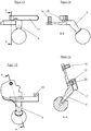
- FIG. 11 A and 11 b show again in the locked and in the unlocked position, the area with the chamber lever 6 and the intermediate piece 17, where you see the chamber lever 6 quasi from below.
- the axle 16 can be seen, around which the chamber lever 6 pivots and you can see the pin 20, which defines the pivot point of the articulated connection between the chamber lever 6 and the intermediate piece 17.
- FIG. 12 shows a section through the chamber lever 6, in which one recognizes the axle 16 and the groove 26 at the top of the intermediate piece 17th
- FIG. 13 shows the chamber lever 6 with the intermediate piece 17 and in the sectional view according to FIG. 14 you can see the chamber lever 6 with the axle 16 for the hinge axis. Furthermore, in FIG. 14 the nose 18 can be seen, via which the intermediate piece 17 is connected to the control piece 4.
- FIG. 15 shows in principle the side view of FIG. 13 , so that you can see the chamber lever 6 from below.
- the section line runs through the axle 16 and through the pin 20 so that it can be seen here how the chamber lever 6 is pivotally connected to the intermediate piece 17 via the pin 20.
Landscapes
- Engineering & Computer Science (AREA)
- General Engineering & Computer Science (AREA)
- Lock And Its Accessories (AREA)
Abstract
Description
- Die vorliegende Erfindung betrifft eine Verschlusseinrichtung für Schusswaffen, insbesondere für Repetiergewehre, umfassend ein Patronenlager, eine außenliegende Hülse und eine in dieser aufgenommene Kammer, wobei die Kammer in dem dem Patronenlager zugewandten Bereich einen Verschlusskopf aufweist und innerhalb der Kammer ein Steuerstück gegenüber der Kammer und gegenüber dem Verschlusskopf axial verschieblich gelagert ist, weiterhin umfassend einen Kammerhebel, welcher mit dem Steuerstück verbunden ist, so dass bei einer Rückwärtsbewegung des Kammerhebels der Verschlusskopf entriegelt und beim Fortlauf verriegelt wird, wobei der Kammerhebel im hinteren Endbereich der Hülse schwenkbar angebracht ist und der Kammerhebel um eine Achse schwenkbar gelagert ist, welche außermittig zur Längsachse der Kammer verläuft.
- Aus der
DE 196 08 872 C1 ist eine Verschlusseinrichtung für Schusswaffen, insbesondere für Repetiergewehre, bekannt mit einem Patronenlager, mit einer außenliegenden Hülse und einer in dieser aufgenommenen Kammer, wobei die Kammer in dem dem Patronenlager zugewandten Bereich einen Verschlusskopf aufweist und innerhalb der Kammer ein Steuerstück gelagert ist, so dass bei der Rückwärtsbewegung des Kammerhebels der Verschlusskopf entriegelt und beim Fortlauf verriegelt wird. Bei dieser bekannten Verschlusseinrichtung ist jedoch der Verschlusskopf nicht drehbar gelagert. Die Verriegelung geschieht über Verriegelungselemente in Form von Kugeln, die über eine abgeschrägte vordere Stirnfläche des Steuerstücks bei dessen Vorschieben nach außen an die Innenwand der Verschlusshülse gedrückt werden. Der Kammerhebel hat zwar bei dieser Waffe eine günstige hintere Position, aber die Verriegelung über die genannten Kugeln hat sich in der Praxis als nachteilig erwiesen. - In der
EP 0 784 194 A2 wird ein Geradzugverschluss für eine Schusswaffe beschrieben, bei dem der Verschlusskopf in einer Kammer drehbar um die eigene Achse gelagert und durch einen Absatz gegenüber der Kammer in seiner Axialbewegung fixiert ist. Eine Steuerhülse weist an ihrer Vorderseite einen Steuerbolzen auf, dessen Oberfläche im Kontakt mit einer Steuernut ist. Bei dieser Schusswaffe befindet sich der Kammergriff konstruktionsbedingt am vorderen Ende es Verschlusses. Diese vordere Position des Kammergriffes erschwert die Handhabung und eine schnelle Waffenfunktion. - Aus der
DE 43 05 700 C1 ist ebenfalls ein Verschluss für eine Schusswaffe bekannt geworden, bei der sich der Geradzughebel direkt über dem Abzug befindet und aufgrund dieser Position eine gute Handhabung erlaubt. Die Verriegelung erfolgt hier jedoch über eine aufspreizbare Hülse, die nicht immer zuverlässig ist.
Bei allen drei vorgenannten bekannten Lösungen weisen die Verschlüsse jeweils nur einen vergleichsweise kurzen Hub des Steuerstücks auf, was durch die Lage der Hebelachse und den Kontaktpunkt mit dem Steuerstück bestimmt ist. Der Hub liegt nur bei etwa 8- 10 mm, was nur eine Verriegelung mit aufspreizbarer Hülse, Kugeln oder begrenzter Drehung in einem Drehwinkel von beispielsweise bis zu etwa 20 ° ermöglicht. - Die Aufgabe der vorliegenden Erfindung besteht darin, einen Verschluss, insbesondere einen Geradzugverschluss, für eine Schusswaffe mit den Merkmalen der eingangs genannten Art zur Verfügung zu stellen, der bei einfacher Bauweise und werkzeugloser Zerlegbarkeit eine sichere Verriegelung über einen drehbaren Verschlusskopf gewährleistet.
- Die Lösung der Aufgabe liefert ein Verschluss für Schusswaffen der eingangs genannten Gattung mit den Merkmalen des Anspruchs 1.
- Erfindungsgemäß ist vorgesehen, dass das Steuerstück über ein Zwischenstück mit dem Kammerhebel verbunden ist, welches von der Kammer aus radial nach außen hin ragt, dass der Verschlusskopf um seine Achse drehbar in der Kammer gelagert ist und der Verschlusskopf durch axiales Verschieben des Steuerstücks gedreht wird.
- Bei der aus der
DE 196 08 872 C1 bekannten Verschlusseinrichtung für Schusswaffen ist der Verschlusskopf nicht drehbar. Zwar gibt es im Stand der Technik auch Geradzugverschlüsse für Schusswaffen, bei denen der Verschlusskopf in einer Kammer drehbar um die eigene Achse gelagert ist, wie beispielsweise in der oben genanntenEP 0 784 194 A2 beschrieben. Jedoch wird bei diesen bekannten Verschlusseinrichtungen aus verschiedenen Gründen konstruktiv bedingt nur ein vergleichsweise geringer Drehwinkel erreicht. - Bei der erfindungsgemäßen Lösung wird hingegen das Steuerstück über ein Zwischenstück mit dem Kammerhebel verbunden. Da die Achse, um die der Kammerhebel schwenkt, außermittig (bezogen auf die Längsachse der Kammer) angeordnet ist und das Zwischenstück, an dem der Kammerhebel angreift, an der der Schwenkachse des Kammerhebels gegenüberliegenden Seite der Waffe angebracht werden kann und dabei noch radial außen liegt, befindet sich auch der Angriffspunkt des Kammerhebels an dem Zwischenstück in einem vergleichsweise großen Abstand zu der Schwenkachse des Kammerhebels, was wiederum zur Folge hat, dass bei der Schwenkbewegung des Kammerhebels ein großer Längshub des Zwischenstücks und damit des Steuerstücks erreicht wird. Dieser vergleichsweise große Längshub des Steuerstücks wird dann in eine Drehbewegung des Verschlusskopfs mit entsprechend großem Drehwinkel umgesetzt, wodurch eine sichere Verriegelung des Verschlusskopfs erreicht wird.
- Gemäß einer bevorzugten Weiterbildung der Erfindung ist das Zwischenstück in wenigstens einer Nut oder Ausnehmung in der Wand der Hülse in Längsrichtung verschieblich geführt. Zum einen ergibt sich dadurch eine zusätzliche Führung für das Zwischenstück in der Hülse und das Zwischenstück kann soweit radial außen angeordnet werden, dass es sich in radialer Richtung nicht nur über die Kammer hinaus, sondern zumindest teilweise auch über die Hülse hinaus nach außen erstreckt.
- Gemäß einer bevorzugten Weiterbildung der Erfindung ist das Zwischenstück außerdem in einem Langloch der Kammer in Längsrichtung verschieblich geführt.
- Gemäß einer bevorzugten Weiterbildung der Erfindung ist eine gelenkige Verbindung des Kammerhebels mit dem Zwischenstück über ein Achselement vorgesehen, dessen Achse parallel zur Achse verläuft, um die der Kammerhebel schwenkbar gelagert ist, wobei das Achselement in der Draufsicht gesehen radial außerhalb der Flucht der Kammer angeordnet ist. Das Achselement weist somit einen vergleichsweise großen Abstand (in Querrichtung der Waffe) zur Schwenkachse des Kammerhebels auf, wodurch sich bei Betätigung des Kammerhebels ein langer Schwenkweg und somit eine große Strecke ergibt, die das Zwischenstück beim Zurückziehen des Kammerhebels zurücklegt. Dies führt wiederum zu einem großen Längshub des Steuerstücks und damit zu einem großen Drehwinkel des Verschlusskopfs.
- Gemäß einer bevorzugten Weiterbildung der Erfindung ist seitlich radial außen in der Kammer etwa in deren hinteren Endbereich ein Rastbolzen angeordnet, welcher mit einer federbelasteten Wippe zusammenwirkt, wobei bei Zurückziehen des Kammerhebels die Wippe und der Rastbolzen von der Hülse freigegeben werden und der Rastbolzen dann in eine entsprechende Ausnehmung des Steuerstücks eingreift, womit dessen Axialbewegung blockiert wird.
- Gemäß einer bevorzugten Weiterbildung der Erfindung befindet sich ein etwa radial nach außen ragender Steuerbolzen im vorderen Bereich an dem Steuerstück, welcher in eine Steuernut in einem Teilabschnitt des Verschlusskopfes eingreift, von dem der vordere Bereich des Steuerstücks konzentrisch aufgenommen wird.
- Gemäß einer bevorzugten Weiterbildung der Erfindung weist das Zwischenstück zur Verbindung mit dem Steuerstück einen Fortsatz oder eine Nase auf, mit dem(r) es radial einwärts ragend in eine radiale Bohrung in dem Steuerstück eingreift.
- Gemäß einer bevorzugten Weiterbildung der Erfindung ist der Achsbolzen, der als Schwenkachse für den Kammerhebel dient, in seiner axialen Richtung eindrückbar gelagert, wobei durch Eindrücken der Kammerhebel freigegeben wird und die Schlagbolzen-Baugruppe axial nach hinten entnehmbar ist.
- Gemäß einer bevorzugten Weiterbildung der Erfindung greift das Achselement, über das der Kammerhebel schwenkbar mit dem Zwischenstück verbunden ist, in eine Quernut an der Unterseite des Zwischenstücks ein.
- Gemäß einer bevorzugten Weiterbildung der Erfindung weist das Zwischenstück oberseitig eine Nut auf, über die es bei Betätigung des Kammerhebels zur Ausführung einer Schwenkbewegung des Kammerhebels gegenüber einem verbreiterten Hinterteil der Kammer verschiebbar geführt ist.
- Die in den Unteransprüchen genannten Merkmale betreffen bevorzugte Weiterbildungen der erfindungsgemäßen Aufgabenlösung. Weitere Vorteile der Erfindung ergeben sich aus der nachfolgenden Detailbeschreibung.
- Nachfolgend wird die vorliegende Erfindung anhand von Ausführungsbeispielen unter Bezugnahme auf die beiliegenden Zeichnungen näher beschrieben.
- Dabei zeigen:
-
Figur 1 einen vertikalen Längsschnitt durch einen Verschluss gemäß einem Ausführungsbeispiel der vorliegenden Erfindung in der verriegelten und abgeschlagenen Stellung ; -
Figur 2 einen horizontalen Längsschnitt durch einen Verschluss gemäß einem Ausführungsbeispiel der vorliegenden Erfindung in der verriegelten und abgeschlagenen Stellung ; -
Figur 3 einen vertikalen Längsschnitt des Verschlusses in der entriegelten Stellung; -
Figur 4 einen horizontalen Längsschnitt des Verschlusses in der entriegelten Stellung; -
Figur 5 einen horizontalen Längsschnitt des Verschlusses in entriegelter Stellung ohne Hülse; -
Figur 6 a eine Seitenansicht von Verschlusskopf und Steuerstück in der verriegelten Stellung, -
Figur 6b eine entsprechende Seitenansicht in der entriegelten Stellung; -
Figur 7 a eine stirnseitige Ansicht der Verschlusskopfs vonFigur 6 a in der verriegelten Stellung gemäßFigur 6 a; -
Figur 7b eine stirnseitige Ansicht des Verschlusskopfs vonFigur 6b in der entriegelten Stellung; -
Figur 8 a eine Ansicht von Kammerhebel und Zwischenstück in der verriegelten Stellung; -
Figur 8b eine Ansicht von Kammerhebel und Zwischenstück in der entriegelten Stellung; -
Figur 9 a eine um 90 ° gedrehte Seitenansicht von Kammerhebel und Zwischenstück gemäßFigur 8 a; -
Figur 9b eine um 90 ° gedrehte Seitenansicht von Kammerhebel und Zwischenstück in der entriegelten Stellung vonFigur 8 b; -
Figur 10 einen Querschnitt entlang der Linie A-A vonFigur 8 b; -
Figur 11 a eine Ansicht des Verschlusses im hinteren Bereich mit Kammerhebel und Zwischenstück in der verriegelten Stellung, wobei man den Verschluss gemäßFigur 9 a hier von der Unterseite her sieht; -
Figur 11b eine entsprechende Ansicht von Kammerhebel und Zwischenstück wie inFigur 11 a , jedoch in der entriegelten Stellung; -
Figur 12 einen Schnitt durch die Darstellung vonFigur 11b entlang der Linie A-A; -
Figur 13 eine Ansicht von Kammerhebel und Zwischenstück in einer ähnlichen Position wie inFigur 8 a; -
Figur 14 eine Schnittansicht entlang der Linie B-B vonFigur 13 ; -
Figur 15 eine gegenüberFigur 13 um 90° gedrehte Ansicht von Kammerhebel und Zwischenstück; -
Figur 16 eine Schnittansicht entlang der Linie A-A vonFigur 15 . - Zunächst wird auf die
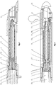
Figuren 1 und 2 Bezug genommen und anhand dieser wird der grundsätzliche Aufbau des erfindungsgemäßen Verschlusses erläutert. Beide Darstellungen zeigen den Verschluss jeweils in der verriegelten und abgeschlagenen Stellung. Es handelt sich um einen in einer im Wesentlichen rohrförmigen zylindrischen Hülse 1 angeordneten Geradzugverschluss, dessen vorderer Verschlusskopf 2 drehbar, aber nicht verschiebbar in einer ebenfalls in der Grundform etwa zylindrischen Kammer 3 gelagert ist, wobei die Kammer 3 wiederum koaxial in der zylindrischen Hülse aufgenommen ist. Wie auch in der stirnseitigen Ansicht gemäß denFiguren 7 a und 7 b erkennbar ist, weist der Verschlusskopf 2 radial außen als Warzen ausgebildete Verriegelungselemente 7 auf, die in entsprechende Verriegelungselemente 8 des Laufes oder der Hülse 1 ein- und ausgekuppelt werden können. An seiner Hinterseite weist der Verschlusskopf 2 wenigstens eine Steuernut 11 auf (siehe auchFiguren 6a, 6b ), die eine konstante oder eine progressive Steigung hat. - Der Verschlusskopf 2 ist durch den Absatz 10 in seiner Axialbewegung gegenüber der Kammer 3 fixiert. Es ist ein Steuerstück 4 vorgesehen, welches im Verschlusskopf 2 und in der Hülse 3 axial verschiebbar gelagert ist. Das Steuerstück 4 weist in seinem vorderen Endbereich einen sich radial nach außen erstreckenden Steuerbolzen 12 auf, dessen Oberfläche im Kontakt mit der Steuernut 11 des Verschlusskopfes 2 ist (siehe auch
Figuren 6 a und 6 b). - In den
Figuren 2 und4 ist der Kammerhebel 6 erkennbar, der schwenkbeweglich und formschlüssig um einen Achsbolzen 16 schwenkbar am hinteren Ende der Kammer 3 gelagert ist (siehe auchFiguren 11a, b und 12 ). Dies ermöglicht eine schnelle und werkzeuglose Zerlegbarkeit. Durch Schwenken des Kammerhebels 6 um den Achsbolzen 16 wird das Steuerstück 4 über ein mit diesem verbundenes Zwischenstück 17 in Axialrichtung bewegt. Die Bewegung des Zwischenstücks 17 kann man recht gut durch Vergleich derFiguren 8a und 8b einerseits sowie auch derFiguren 11a und 11b erkennen.
Das Zwischenstück 17 ist in der Kammer 3 axial verschiebbar gelagert und durch die Nase 18 mit dem Steuerstück 4 verbunden (sieheFiguren 2 und4 ). Am hinteren Ende ist das Zwischenstück 17 durch die Quernut 19 und das Achselement 20 mit dem Kammerhebel 6 verbunden (sieheFigur 16 ). - Am hinteren Ende der Kammer 3 ist auf der dem Zwischenstück 17 am Umfang gegenüber liegenden Seite der Kammer 3 ein Rastbolzen 21 mit einer unter Federdruck stehenden Wippe 22 angeordnet (siehe
Figur 2 ). Dieser Rastbolzen 21 rastet in eine Ausnehmung 23 (sieheFigur 2 ) ein, wenn man beim Repetieren der Waffe die Kammer 3 aus der Hülse 1 bewegt (sieheFigur 4 ). - Die Funktionsweise des erfindungsgemäßen Verschlusses wird nachfolgend erläutert. Bei der Bewegung des Verschlusses in die in den
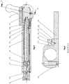
Figuren 1 und 2 gezeigte verriegelte und abgeschlagene Stellung wird der Kammerhebel 6 nach vorn bewegt und geschwenkt, wodurch auch das Zwischenstück 17 und das Steuerstück 4 in eine vordere Position bewegt werden. Zum Öffnen des Verschlusses wird der Kammerhebel 6 zurückgezogen, wodurch auch das Zwischenstück 17 und das mit diesem verbundene Steuerstück 4 zurückgezogen werden in die in denFiguren 3 und 4 dargestellte Position. Während der Rückwärtsbewegung wird über die in den Verschlusskopf 2 eingebrachte Steuernut 11 und den Steuerbolzen 12 der Verschlusskopf 2 um die eigene Achse 13 gedreht und dadurch entriegelt. Hier wird auch auf dieFiguren 6 a und 6 b verwiesen, die das Steuerstück 4 in der vorderen und in der herausgezogenen hinteren Position zeigen. Man kann hier gut erkennen, wie sich der Steuerbolzen 12 in der Steuernut 11 bewegt. Da der Verschlusskopf 2 in axialer Richtung festgehalten wird, dreht er sich beim Zurückziehen des Steuerstücks um seine Achse. Die beiden Drehpositionen des Verschlusskopfs sind auch in denFiguren 7 a und 7 b dargestellt, die den Verschlusskopf 2 von der Stirnseite her zeigen. - Beim weiteren Zurückziehen des Kammerhebels 6 (siehe
Figur 5 ) wird die Wippe 22 und somit der Rastbolzen 21 von der Hülse 1 freigegeben. Dies bedeutet, dass der Rastbolzen 21 in die entsprechende Ausnehmung des Steuerstücks 4 eingreift und dessen Axialbewegung blockiert. Der Verschlusskopf 2 kann nun mit der Kammer 3 und dem Steuerstück 4 in axialer Richtung nach hinten hin aus der Hülse herausgezogen werden. Es findet dann keine Drehbewegung des Verschlusskopfs 2 und keine Axialbewegung des Steuerstücks 4 innerhalb der Kammer 3 mehr statt. - Wenn Kammerhebel 6 und Verschlusskopf 2 in der entriegelten Stellung fixiert sind, kann der Verschluss ungehindert gleiten und dadurch wird der Repetiervorgang ausgeführt.
- Beim Schließen des Verschlusses (
Figur 4 ) wird der Kammerhebel 6 und somit der Verschlusskopf 2 erst dann zur Drehbewegung freigegeben, wenn die Wippe 22 über die Kante der Hülse 1 weiter nach vorne geschoben wird (siehe auchFigur 5 ). - Das Steuerstück 4 wird durch die Schließfeder 9 nach vorn gedrückt, was den Schließvorgang erleichtert und den Verschlusskopf 2 in der verriegelten Stellung hält (siehe
Figur 2 ). - In den
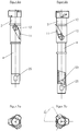
Figuren 6 a und 6 b ist das Steuerstück 4 ohne die Kammer 3 dargestellt, in der es axial verschieblich gelagert ist. Man erkennt hier recht gut die Steuernut 11 im Verschlusskopf 2 und den Steuerbolzen 12, welcher in dieser Steuernut 11 geführt ist. Wird nun aus der verriegelten Stellung gemäßFigur 6 a das Steuerstück 4 über das hier nicht abgebildete Zwischenstück 17 nach hinten bewegt, dann führt dies zu der Drehbewegung des Verschlusskopfes in die inFigur 6b dargestellte Stellung. Durch Vergleich dieser beiden Ansichten wird der vergleichsweise große Längshub des Steuerstücks 4 erkennbar. In diesen beiden Zeichnungen sieht man außerdem die radiale Bohrung 25 des Steuerstücks 4, in die die Nase 18 (sieheFigur 2 ) des Zwischenstücks eingreift, wodurch die Verbindung zwischen Zwischenstück 17 und Steuerstück 4 hergestellt wird. - Die stirnseitigen Ansichten gemäß den
Figuren 7 a und 7 b lassen die Größe des Drehwinkels bei dem zuvor beschriebenen Vorgang der Verriegelung des Verschlusskopfes 2 erkennen und man sieht, dass es sich um einen Drehwinkel von ca. 60° handelt, was erheblich mehr ist, als bei aus dem Stand der Technik bekannten Vorrichtungen. Weiterhin sieht man in denFiguren 7 a und 7 b die Umrissform des Verschlusskopfs 2 in seinem Endbereich, die mit Nasen, Vorsprüngen oder dergleichen so geformt ist, dass in der Stellung gemäßFiguren 7 a/6 a die Verriegelung gegeben ist, während nach der Drehung in die Position gemäßFigur 7b der Verschlusskopf 2 formschlüssig in eine entsprechend geformte Innenkontur in der Hülse 1 passt und daher in der Hülse zurückgleiten kann. Diesbezüglich wird auch auf die jeweiligen Verriegelungselemente 7, 8 von Verschlusskopf 2 und Hülse 1 verwiesen, die in der Darstellung gemäß denFiguren 3 und 4 nach der Entriegelung freiliegen. - Die
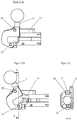
Figuren 8 a und 8 b zeigen jeweils eine Seitenansicht im hinteren Bereich der Waffe, wobei man die Verbindung von Zwischenstück 17 und Kammerhebel 6 erkennt, sowie das Langloch 24 in der Kammer, in dem das Zwischenstück 17 in der ersten Phase der Bewegung des Kammerhebels 6 nach hinten, bis zur Entriegelung des Verschlusskopfes 2 geführt ist. In der zweiten Bewegungsphase, nachdem der Rastbolzen 21 freigegeben wurde, bewegt sich der Verschluss mit der Kammer 3 aus der Hülse 1 heraus axial nach hinten und das Zwischenstück 17 ist dann gegenüber der Kammer 3 arretiert. - Die
Figuren 9 a und 9 b zeigen die jeweiligen Seitenansichten derFiguren 8 a und 8 b, wobei man inFigur 9 von oben her auf die Waffe schaut. Man erkennt hier, dass das Zwischenstück 17 oberseitig eine Nut 26 aufweist, über die es bei Betätigung des Kammerhebels 6 zur Ausführung dessen Schwenkbewegung gegenüber dem Hinterteil der Kammer verschiebbar geführt ist. Weil das Zwischenstück 17 so in zwei zueinander rechtwinkligen Bereichen geführt ist (einmal an der Hülse 1 und einmal an dem breiteren Hinterteil der Kammer 3), ist es bei seiner Bewegung an der Waffe gefangen. Das genannte verbreiterte Hinterteil der Kammer ist so ausgeführt, dass es bei in die Hülse 1 eingeschobener Kammer 3 bündig am hinteren Ende der Hülse 1 anliegt (sieheFiguren 1 und 2 ). - Die
Figuren 11 a und 11 b zeigen wiederum in der verriegelten und in der entriegelten Stellung den Bereich mit dem Kammerhebel 6 und dem Zwischenstück 17, wobei man hier den Kammerhebel 6 quasi von unten her sieht. Hier ist zum einen der Achsbolzen 16 erkennbar, um den der Kammerhebel 6 schwenkt und man sieht den Stift 20, der den Schwenkpunkt der gelenkigen Verbindung zwischen dem Kammerhebel 6 und dem Zwischenstück 17 definiert.Figur 12 zeigt einen Schnitt durch den Kammerhebel 6, in dem man den Achsbolzen 16 erkennt und die Nut 26 an der Oberseite des Zwischenstücks 17. -
Figur 13 zeigt den Kammerhebel 6 mit dem Zwischenstück 17 und in der Schnittansicht gemäßFigur 14 sieht man den Kammerhebel 6 mit dem Achsbolzen 16 für dessen Gelenkachse. Weiterhin ist inFigur 14 die Nase 18 erkennbar, über die das Zwischenstück 17 mit dem Steuerstück 4 verbunden wird.Figur 15 zeigt im Prinzip die Seitenansicht vonFigur 13 , so dass man den Kammerhebel 6 von unten her sieht. Bei der Schnittansicht gemäßFigur 16 verläuft die Schnittlinie durch den Achsbolzen 16 und durch den Stift 20, so dass man hier erkennt, wie der Kammerhebel 6 mit dem Zwischenstück 17 gelenkig über den Stift 20 verbunden ist. -
- 1
- Hülse
- 2
- Verschlusskopf
- 3
- Kammer
- 4
- Steuerstück
- 5
- Patronenlager
- 6
- Kammerhebel
- 7
- Verriegelungselemente
- 8
- Verriegelungselemente
- 9
- Schließfeder
- 10
- Absatz
- 11
- Steuernut
- 12
- Steuerbolzen
- 13
- Achse
- 14
- Absatz
- 15
- Nut
- 16
- Achsbolzen
- 17
- Zwischenstück
- 18
- Nase
- 19
- Quernut
- 20
- Achselement
- 21
- Rastbolzen
- 22
- Wippe
- 23
- Ausnehmung
- 24
- Langloch
- 25
- radiale Bohrung
- 26
- Nut
Claims (10)
- Verschlusseinrichtung für Schusswaffen, insbesondere für Repetiergewehre, umfassend ein Patronenlager, eine außenliegende Hülse (1) und eine in dieser aufgenommene Kammer (3), wobei die Kammer (3) in dem dem Patronenlager zugewandten Bereich einen Verschlusskopf (2) aufweist und innerhalb der Kammer (3) ein Steuerstück (4) gegenüber der Kammer (3) und gegenüber dem Verschlusskopf (2) axial verschieblich gelagert ist, weiterhin umfassend einen Kammerhebel (6), welcher mit dem Steuerstück (4) verbunden ist, so dass bei einer Rückwärtsbewegung des Kammerhebels (6) der Verschlusskopf (2) entriegelt und beim Fortlauf verriegelt wird, wobei der Kammerhebel (6) im hinteren Endbereich der Hülse (1) schwenkbar angebracht ist und der Kammerhebel um eine Achse schwenkbar gelagert ist, welche außermittig zur Längsachse der Kammer (3) verläuft, dadurch gekennzeichnet, dass das Steuerstück (4) über ein Zwischenstück (17) mit dem Kammerhebel (6) verbunden ist, welches von der Kammer aus radial nach außen hin ragt, dass der Verschlusskopf (2) um seine Achse (13) drehbar in der Kammer (3) gelagert ist und der Verschlusskopf (2) durch axiales Verschieben des Steuerstücks (4) gedreht wird.
- Verschlusseinrichtung für Schusswaffen nach Anspruch 1, dadurch gekennzeichnet, dass das Zwischenstück in wenigstens einer Nut oder Ausnehmung in der Wand der Hülse (1) in Längsrichtung verschieblich geführt ist.
- Verschlusseirichtung für Schusswaffen nach Anspruch 1 oder 2, dadurch gekennzeichnet, dass das Zwischenstück (17) in einem Langloch (24) der Kammer (3) in Längsrichtung verschieblich geführt ist.
- Verschlusseinrichtung nach einem der Ansprüche 1 bis 3, dadurch gekennzeichnet, dass eine gelenkige Verbindung des Kammerhebels (6) mit dem Zwischenstück über ein Achselement (20) vorgesehen ist, dessen Achse parallel zur Achse (16) verläuft, um die der Kammerhebel (6) schwenkbar gelagert ist, wobei das Achselement (20) in der Draufsicht gesehen radial außerhalb der Flucht der Kammer angeordnet ist.
- Verschlusseinrichtung nach einem der Ansprüche 1 bis 4, dadurch gekennzeichnet, dass seitlich radial außen in der Kammer (3) etwa in deren hinteren Endbereich ein Rastbolzen (21) angeordnet ist, welcher mit einer federbelasteten Wippe (22) zusammenwirkt, wobei bei Zurückziehen des Kammerhebels (6) die Wippe (22) und der Rastbolzen (21) von der Hülse (1) freigegeben werden und der Rastbolzen (21) dann in eine entsprechende Ausnehmung (23) des Steuerstücks (4) eingreift, womit dessen Axialbewegung blockiert wird.
- Verschlusseinrichtung nach einem der Ansprüche 1 bis 5, dadurch gekennzeichnet, dass sich ein etwa radial nach außen ragender Steuerbolzen (12) im vorderen Bereich an dem Steuerstück (4) befindet, welcher in eine Steuernut (11) in einem Teilabschnitt des Verschlusskopfes (2) eingreift, von dem der vordere Bereich des Steuerstücks (4) konzentrisch aufgenommen wird.
- Verschlusseinrichtung nach einem der Ansprüche 1 bis 6, dadurch gekennzeichnet, dass das Zwischenstück (17) zur Verbindung mit dem Steuerstück (4) einen Fortsatz oder eine Nase (18) aufweist, mit dem(r) es radial einwärts ragend in eine radiale Bohrung (25) in dem Steuerstück (4) eingreift.
- Verschlusseinrichtung nach einem der Ansprüche 4 bis 7, dadurch gekennzeichnet, dass der Achsbolzen (16) in seiner axialen Richtung eindrückbar gelagert ist, wobei durch Eindrücken der Kammerhebel (6) freigegeben wird und die Schlagbolzen-Baugruppe axial nach hinten entnehmbar ist.
- Verschlusseinrichtung nach einem der Ansprüche 4 bis 8, dadurch gekennzeichnet, dass das Achselement (20), über das der Kammerhebel (6) schwenkbar mit dem Zwischenstück (17) verbunden ist, in eine Quernut (19) an der Unterseite des Zwischenstücks (17) eingreift.
- Verschlusseinrichtung nach einem der Ansprüche 2 bis 9, dadurch gekennzeichnet, dass das Zwischenstück (17) oberseitig eine Nut (26) aufweist, über die es bei Betätigung des Kammerhebels zur Ausführung einer Schwenkbewegung des Kammerhebels (6) gegenüber einem verbreiterten Hinterteil der Kammer (3) verschiebbar geführt ist.
Priority Applications (1)
| Application Number | Priority Date | Filing Date | Title |
|---|---|---|---|
| EP17161425.8A EP3376151B1 (de) | 2017-03-16 | 2017-03-16 | Verschluss für schusswaffen |
Applications Claiming Priority (1)
| Application Number | Priority Date | Filing Date | Title |
|---|---|---|---|
| EP17161425.8A EP3376151B1 (de) | 2017-03-16 | 2017-03-16 | Verschluss für schusswaffen |
Publications (2)
| Publication Number | Publication Date |
|---|---|
| EP3376151A1 true EP3376151A1 (de) | 2018-09-19 |
| EP3376151B1 EP3376151B1 (de) | 2020-02-12 |
Family
ID=58358432
Family Applications (1)
| Application Number | Title | Priority Date | Filing Date |
|---|---|---|---|
| EP17161425.8A Active EP3376151B1 (de) | 2017-03-16 | 2017-03-16 | Verschluss für schusswaffen |
Country Status (1)
| Country | Link |
|---|---|
| EP (1) | EP3376151B1 (de) |
Citations (6)
| Publication number | Priority date | Publication date | Assignee | Title |
|---|---|---|---|---|
| DE49192C (de) * | EISENWERKE GAGGE-NAU, Actien - Gesellschaft in Gaggenau, Baden | GeradezugVerschlufs mit wagrecht schwingendem Handgriff | ||
| DE3432537A1 (de) * | 1984-09-05 | 1986-03-13 | Peter 8201 Rohrdorf Fortner jun. | Repetiergewehr, insbesondere als sportgewehr wie fuer biathlon |
| DE4305700C1 (de) | 1993-02-25 | 1994-10-27 | Blaser Horst Jagdwaffen | Verschluß für eine Schußwaffe, insbesondere ein Repetiergewehr |
| DE19608872C1 (de) | 1996-03-07 | 1997-06-05 | Peter Fortner | Verschlußeinrichtung für Schußwaffen, insbesondere für Repetiergewehre |
| EP0784194A2 (de) | 1996-01-09 | 1997-07-16 | Mauser-Werke Oberndorf Waffensysteme GmbH | Verschluss für eine Schusswaffe |
| DE102012217686A1 (de) * | 2012-09-28 | 2014-04-03 | Andreas Volckmann | Geradezug-Repetiergewehr mit einem Verschlussmechanismus |
-
2017
- 2017-03-16 EP EP17161425.8A patent/EP3376151B1/de active Active
Patent Citations (6)
| Publication number | Priority date | Publication date | Assignee | Title |
|---|---|---|---|---|
| DE49192C (de) * | EISENWERKE GAGGE-NAU, Actien - Gesellschaft in Gaggenau, Baden | GeradezugVerschlufs mit wagrecht schwingendem Handgriff | ||
| DE3432537A1 (de) * | 1984-09-05 | 1986-03-13 | Peter 8201 Rohrdorf Fortner jun. | Repetiergewehr, insbesondere als sportgewehr wie fuer biathlon |
| DE4305700C1 (de) | 1993-02-25 | 1994-10-27 | Blaser Horst Jagdwaffen | Verschluß für eine Schußwaffe, insbesondere ein Repetiergewehr |
| EP0784194A2 (de) | 1996-01-09 | 1997-07-16 | Mauser-Werke Oberndorf Waffensysteme GmbH | Verschluss für eine Schusswaffe |
| DE19608872C1 (de) | 1996-03-07 | 1997-06-05 | Peter Fortner | Verschlußeinrichtung für Schußwaffen, insbesondere für Repetiergewehre |
| DE102012217686A1 (de) * | 2012-09-28 | 2014-04-03 | Andreas Volckmann | Geradezug-Repetiergewehr mit einem Verschlussmechanismus |
Also Published As
| Publication number | Publication date |
|---|---|
| EP3376151B1 (de) | 2020-02-12 |
Similar Documents
| Publication | Publication Date | Title |
|---|---|---|
| DE102016120891A1 (de) | Verschluss für Schusswaffen | |
| AT392818B (de) | Schliesssystem | |
| DE29820711U1 (de) | Drehriegelverschluß mit Zugeinrichtung | |
| DE2711124B1 (de) | Handpipette | |
| WO2016197162A1 (de) | AUSSTOßVORRICHTUNG FÜR EIN BEWEGBARES MÖBELTEIL | |
| EP1688566B1 (de) | Schloss mit Schwenkauslöser | |
| DE3609043C2 (de) | Elektrische Sicherheitsschaltvorrichtung | |
| DE69207320T2 (de) | Verbesserter Schloss mit einer Einrichtung zwecks Öffnen im Notfall | |
| DE2910295C2 (de) | Abschließbarer Drehgriff für Fenster und Türen | |
| DE19939734B4 (de) | Aus Schließzylinder und Schlüssel bestehende Schließvorrichtung | |
| EP0597170B1 (de) | Drehriegelverschluss | |
| EP3426867B1 (de) | Schloss | |
| DE2347405C3 (de) | Zylinderförmiges Einsteckschloß | |
| EP3034728A1 (de) | Öffnungsbegrenzereinrichtung | |
| EP3376151B1 (de) | Verschluss für schusswaffen | |
| DE3630747C2 (de) | Türschloß, insbesondere Einsteckschloß | |
| DE3427713A1 (de) | Mehrtourig schliessendes treibstangenschloss | |
| DE69807608T2 (de) | Schliessvorrichtung, insbesondere Einsteckschloss mit einer Falle, für eine Fenstertür oder dergleichen | |
| DE69204044T2 (de) | Sicherheitsschloss für eine Haustüre oder dgl. | |
| DE69807801T2 (de) | Verriegelungsvorrichtung, insbesondere Einsteckschloss für den Flügel einer Tür oder eines Fensters | |
| DE19604594C1 (de) | Kombination eines Schließzylinders und eines Flachschlüssels für Waren- und Spielautomaten, Geldwechselautomaten, Fahrkartenautomaten und dergleichen, mit Stiftzuhaltungen | |
| DE2743091C2 (de) | Vorrichtung zum Vergrößern des Ausschließhubes eines eintourig mittels Schlüssel schließbaren Schubriegels in einem Schloß mit Falle und Schubriegel | |
| DE3427712A1 (de) | Treibstangenschloss | |
| EP0806534B1 (de) | Treibstangenschloss | |
| DE4014042A1 (de) | Treibstangenschloss |
Legal Events
| Date | Code | Title | Description |
|---|---|---|---|
| PUAI | Public reference made under article 153(3) epc to a published international application that has entered the european phase |
Free format text: ORIGINAL CODE: 0009012 |
|
| STAA | Information on the status of an ep patent application or granted ep patent |
Free format text: STATUS: REQUEST FOR EXAMINATION WAS MADE |
|
| 17P | Request for examination filed |
Effective date: 20171006 |
|
| AK | Designated contracting states |
Kind code of ref document: A1 Designated state(s): AL AT BE BG CH CY CZ DE DK EE ES FI FR GB GR HR HU IE IS IT LI LT LU LV MC MK MT NL NO PL PT RO RS SE SI SK SM TR |
|
| AX | Request for extension of the european patent |
Extension state: BA ME |
|
| RIC1 | Information provided on ipc code assigned before grant |
Ipc: F41A 3/20 20060101AFI20190902BHEP |
|
| GRAP | Despatch of communication of intention to grant a patent |
Free format text: ORIGINAL CODE: EPIDOSNIGR1 |
|
| STAA | Information on the status of an ep patent application or granted ep patent |
Free format text: STATUS: GRANT OF PATENT IS INTENDED |
|
| INTG | Intention to grant announced |
Effective date: 20191115 |
|
| GRAS | Grant fee paid |
Free format text: ORIGINAL CODE: EPIDOSNIGR3 |
|
| GRAA | (expected) grant |
Free format text: ORIGINAL CODE: 0009210 |
|
| STAA | Information on the status of an ep patent application or granted ep patent |
Free format text: STATUS: THE PATENT HAS BEEN GRANTED |
|
| AK | Designated contracting states |
Kind code of ref document: B1 Designated state(s): AL AT BE BG CH CY CZ DE DK EE ES FI FR GB GR HR HU IE IS IT LI LT LU LV MC MK MT NL NO PL PT RO RS SE SI SK SM TR |
|
| REG | Reference to a national code |
Ref country code: GB Ref legal event code: FG4D Free format text: NOT ENGLISH |
|
| REG | Reference to a national code |
Ref country code: CH Ref legal event code: EP |
|
| REG | Reference to a national code |
Ref country code: AT Ref legal event code: REF Ref document number: 1232689 Country of ref document: AT Kind code of ref document: T Effective date: 20200215 |
|
| REG | Reference to a national code |
Ref country code: IE Ref legal event code: FG4D Free format text: LANGUAGE OF EP DOCUMENT: GERMAN |
|
| REG | Reference to a national code |
Ref country code: DE Ref legal event code: R096 Ref document number: 502017003721 Country of ref document: DE |
|
| REG | Reference to a national code |
Ref country code: CH Ref legal event code: NV Representative=s name: DENNEMEYER AG, CH |
|
| REG | Reference to a national code |
Ref country code: FI Ref legal event code: FGE |
|
| REG | Reference to a national code |
Ref country code: SE Ref legal event code: TRGR |
|
| PG25 | Lapsed in a contracting state [announced via postgrant information from national office to epo] |
Ref country code: RS Free format text: LAPSE BECAUSE OF FAILURE TO SUBMIT A TRANSLATION OF THE DESCRIPTION OR TO PAY THE FEE WITHIN THE PRESCRIBED TIME-LIMIT Effective date: 20200212 Ref country code: NO Free format text: LAPSE BECAUSE OF FAILURE TO SUBMIT A TRANSLATION OF THE DESCRIPTION OR TO PAY THE FEE WITHIN THE PRESCRIBED TIME-LIMIT Effective date: 20200512 |
|
| REG | Reference to a national code |
Ref country code: LT Ref legal event code: MG4D |
|
| REG | Reference to a national code |
Ref country code: NL Ref legal event code: MP Effective date: 20200212 |
|
| PG25 | Lapsed in a contracting state [announced via postgrant information from national office to epo] |
Ref country code: LV Free format text: LAPSE BECAUSE OF FAILURE TO SUBMIT A TRANSLATION OF THE DESCRIPTION OR TO PAY THE FEE WITHIN THE PRESCRIBED TIME-LIMIT Effective date: 20200212 Ref country code: BG Free format text: LAPSE BECAUSE OF FAILURE TO SUBMIT A TRANSLATION OF THE DESCRIPTION OR TO PAY THE FEE WITHIN THE PRESCRIBED TIME-LIMIT Effective date: 20200512 Ref country code: IS Free format text: LAPSE BECAUSE OF FAILURE TO SUBMIT A TRANSLATION OF THE DESCRIPTION OR TO PAY THE FEE WITHIN THE PRESCRIBED TIME-LIMIT Effective date: 20200612 Ref country code: GR Free format text: LAPSE BECAUSE OF FAILURE TO SUBMIT A TRANSLATION OF THE DESCRIPTION OR TO PAY THE FEE WITHIN THE PRESCRIBED TIME-LIMIT Effective date: 20200513 Ref country code: HR Free format text: LAPSE BECAUSE OF FAILURE TO SUBMIT A TRANSLATION OF THE DESCRIPTION OR TO PAY THE FEE WITHIN THE PRESCRIBED TIME-LIMIT Effective date: 20200212 |
|
| PG25 | Lapsed in a contracting state [announced via postgrant information from national office to epo] |
Ref country code: NL Free format text: LAPSE BECAUSE OF FAILURE TO SUBMIT A TRANSLATION OF THE DESCRIPTION OR TO PAY THE FEE WITHIN THE PRESCRIBED TIME-LIMIT Effective date: 20200212 |
|
| PG25 | Lapsed in a contracting state [announced via postgrant information from national office to epo] |
Ref country code: SK Free format text: LAPSE BECAUSE OF FAILURE TO SUBMIT A TRANSLATION OF THE DESCRIPTION OR TO PAY THE FEE WITHIN THE PRESCRIBED TIME-LIMIT Effective date: 20200212 Ref country code: SM Free format text: LAPSE BECAUSE OF FAILURE TO SUBMIT A TRANSLATION OF THE DESCRIPTION OR TO PAY THE FEE WITHIN THE PRESCRIBED TIME-LIMIT Effective date: 20200212 Ref country code: EE Free format text: LAPSE BECAUSE OF FAILURE TO SUBMIT A TRANSLATION OF THE DESCRIPTION OR TO PAY THE FEE WITHIN THE PRESCRIBED TIME-LIMIT Effective date: 20200212 Ref country code: DK Free format text: LAPSE BECAUSE OF FAILURE TO SUBMIT A TRANSLATION OF THE DESCRIPTION OR TO PAY THE FEE WITHIN THE PRESCRIBED TIME-LIMIT Effective date: 20200212 Ref country code: ES Free format text: LAPSE BECAUSE OF FAILURE TO SUBMIT A TRANSLATION OF THE DESCRIPTION OR TO PAY THE FEE WITHIN THE PRESCRIBED TIME-LIMIT Effective date: 20200212 Ref country code: LT Free format text: LAPSE BECAUSE OF FAILURE TO SUBMIT A TRANSLATION OF THE DESCRIPTION OR TO PAY THE FEE WITHIN THE PRESCRIBED TIME-LIMIT Effective date: 20200212 Ref country code: PT Free format text: LAPSE BECAUSE OF FAILURE TO SUBMIT A TRANSLATION OF THE DESCRIPTION OR TO PAY THE FEE WITHIN THE PRESCRIBED TIME-LIMIT Effective date: 20200705 Ref country code: RO Free format text: LAPSE BECAUSE OF FAILURE TO SUBMIT A TRANSLATION OF THE DESCRIPTION OR TO PAY THE FEE WITHIN THE PRESCRIBED TIME-LIMIT Effective date: 20200212 |
|
| REG | Reference to a national code |
Ref country code: DE Ref legal event code: R097 Ref document number: 502017003721 Country of ref document: DE |
|
| PG25 | Lapsed in a contracting state [announced via postgrant information from national office to epo] |
Ref country code: MC Free format text: LAPSE BECAUSE OF FAILURE TO SUBMIT A TRANSLATION OF THE DESCRIPTION OR TO PAY THE FEE WITHIN THE PRESCRIBED TIME-LIMIT Effective date: 20200212 |
|
| REG | Reference to a national code |
Ref country code: DE Ref legal event code: R082 Ref document number: 502017003721 Country of ref document: DE Representative=s name: FRITZ & BRANDENBURG PATENTANWAELTE, DE |
|
| PLBE | No opposition filed within time limit |
Free format text: ORIGINAL CODE: 0009261 |
|
| STAA | Information on the status of an ep patent application or granted ep patent |
Free format text: STATUS: NO OPPOSITION FILED WITHIN TIME LIMIT |
|
| PG25 | Lapsed in a contracting state [announced via postgrant information from national office to epo] |
Ref country code: LU Free format text: LAPSE BECAUSE OF NON-PAYMENT OF DUE FEES Effective date: 20200316 |
|
| 26N | No opposition filed |
Effective date: 20201113 |
|
| PG25 | Lapsed in a contracting state [announced via postgrant information from national office to epo] |
Ref country code: IE Free format text: LAPSE BECAUSE OF NON-PAYMENT OF DUE FEES Effective date: 20200316 |
|
| PG25 | Lapsed in a contracting state [announced via postgrant information from national office to epo] |
Ref country code: SI Free format text: LAPSE BECAUSE OF FAILURE TO SUBMIT A TRANSLATION OF THE DESCRIPTION OR TO PAY THE FEE WITHIN THE PRESCRIBED TIME-LIMIT Effective date: 20200212 Ref country code: PL Free format text: LAPSE BECAUSE OF FAILURE TO SUBMIT A TRANSLATION OF THE DESCRIPTION OR TO PAY THE FEE WITHIN THE PRESCRIBED TIME-LIMIT Effective date: 20200212 |
|
| GBPC | Gb: european patent ceased through non-payment of renewal fee |
Effective date: 20210316 |
|
| PG25 | Lapsed in a contracting state [announced via postgrant information from national office to epo] |
Ref country code: GB Free format text: LAPSE BECAUSE OF NON-PAYMENT OF DUE FEES Effective date: 20210316 |
|
| REG | Reference to a national code |
Ref country code: DE Ref legal event code: R082 Ref document number: 502017003721 Country of ref document: DE Representative=s name: DUDA, RAFAEL THOMAS, DIPL.-ING. DR. RER. NAT., DE |
|
| PG25 | Lapsed in a contracting state [announced via postgrant information from national office to epo] |
Ref country code: TR Free format text: LAPSE BECAUSE OF FAILURE TO SUBMIT A TRANSLATION OF THE DESCRIPTION OR TO PAY THE FEE WITHIN THE PRESCRIBED TIME-LIMIT Effective date: 20200212 Ref country code: MT Free format text: LAPSE BECAUSE OF FAILURE TO SUBMIT A TRANSLATION OF THE DESCRIPTION OR TO PAY THE FEE WITHIN THE PRESCRIBED TIME-LIMIT Effective date: 20200212 Ref country code: CY Free format text: LAPSE BECAUSE OF FAILURE TO SUBMIT A TRANSLATION OF THE DESCRIPTION OR TO PAY THE FEE WITHIN THE PRESCRIBED TIME-LIMIT Effective date: 20200212 |
|
| PG25 | Lapsed in a contracting state [announced via postgrant information from national office to epo] |
Ref country code: MK Free format text: LAPSE BECAUSE OF FAILURE TO SUBMIT A TRANSLATION OF THE DESCRIPTION OR TO PAY THE FEE WITHIN THE PRESCRIBED TIME-LIMIT Effective date: 20200212 Ref country code: AL Free format text: LAPSE BECAUSE OF FAILURE TO SUBMIT A TRANSLATION OF THE DESCRIPTION OR TO PAY THE FEE WITHIN THE PRESCRIBED TIME-LIMIT Effective date: 20200212 |
|
| P01 | Opt-out of the competence of the unified patent court (upc) registered |
Effective date: 20230914 |
|
| PGFP | Annual fee paid to national office [announced via postgrant information from national office to epo] |
Ref country code: AT Payment date: 20240321 Year of fee payment: 8 |
|
| PGFP | Annual fee paid to national office [announced via postgrant information from national office to epo] |
Ref country code: FI Payment date: 20240320 Year of fee payment: 8 Ref country code: CZ Payment date: 20240307 Year of fee payment: 8 |
|
| PGFP | Annual fee paid to national office [announced via postgrant information from national office to epo] |
Ref country code: SE Payment date: 20240320 Year of fee payment: 8 Ref country code: IT Payment date: 20240322 Year of fee payment: 8 Ref country code: FR Payment date: 20240328 Year of fee payment: 8 Ref country code: BE Payment date: 20240320 Year of fee payment: 8 |
|
| PGFP | Annual fee paid to national office [announced via postgrant information from national office to epo] |
Ref country code: CH Payment date: 20240401 Year of fee payment: 8 |
|
| PG25 | Lapsed in a contracting state [announced via postgrant information from national office to epo] |
Ref country code: FI Free format text: LAPSE BECAUSE OF NON-PAYMENT OF DUE FEES Effective date: 20250316 |
|
| PG25 | Lapsed in a contracting state [announced via postgrant information from national office to epo] |
Ref country code: CZ Free format text: LAPSE BECAUSE OF NON-PAYMENT OF DUE FEES Effective date: 20250316 |
|
| REG | Reference to a national code |
Ref country code: CH Ref legal event code: H13 Free format text: ST27 STATUS EVENT CODE: U-0-0-H10-H13 (AS PROVIDED BY THE NATIONAL OFFICE) Effective date: 20251023 |
|
| REG | Reference to a national code |
Ref country code: SE Ref legal event code: EUG |
|
| REG | Reference to a national code |
Ref country code: AT Ref legal event code: MM01 Ref document number: 1232689 Country of ref document: AT Kind code of ref document: T Effective date: 20250316 |
|
| REG | Reference to a national code |
Ref country code: BE Ref legal event code: MM Effective date: 20250331 |
|
| PG25 | Lapsed in a contracting state [announced via postgrant information from national office to epo] |
Ref country code: AT Free format text: LAPSE BECAUSE OF NON-PAYMENT OF DUE FEES Effective date: 20250316 |
|
| PG25 | Lapsed in a contracting state [announced via postgrant information from national office to epo] |
Ref country code: FR Free format text: LAPSE BECAUSE OF NON-PAYMENT OF DUE FEES Effective date: 20250331 Ref country code: IT Free format text: LAPSE BECAUSE OF NON-PAYMENT OF DUE FEES Effective date: 20250316 |
|
| PG25 | Lapsed in a contracting state [announced via postgrant information from national office to epo] |
Ref country code: BE Free format text: LAPSE BECAUSE OF NON-PAYMENT OF DUE FEES Effective date: 20250331 |
|
| PG25 | Lapsed in a contracting state [announced via postgrant information from national office to epo] |
Ref country code: CH Free format text: LAPSE BECAUSE OF NON-PAYMENT OF DUE FEES Effective date: 20250331 |
|
| PG25 | Lapsed in a contracting state [announced via postgrant information from national office to epo] |
Ref country code: SE Free format text: LAPSE BECAUSE OF NON-PAYMENT OF DUE FEES Effective date: 20250317 |
|
| PGFP | Annual fee paid to national office [announced via postgrant information from national office to epo] |
Ref country code: DE Payment date: 20260320 Year of fee payment: 10 |