EP3376151A1 - Culasse pour une arme à feu - Google Patents
Culasse pour une arme à feu Download PDFInfo
- Publication number
- EP3376151A1 EP3376151A1 EP17161425.8A EP17161425A EP3376151A1 EP 3376151 A1 EP3376151 A1 EP 3376151A1 EP 17161425 A EP17161425 A EP 17161425A EP 3376151 A1 EP3376151 A1 EP 3376151A1
- Authority
- EP
- European Patent Office
- Prior art keywords
- chamber
- lever
- control piece
- closure
- piece
- Prior art date
- Legal status (The legal status is an assumption and is not a legal conclusion. Google has not performed a legal analysis and makes no representation as to the accuracy of the status listed.)
- Granted
Links
Images


Classifications
-
- F—MECHANICAL ENGINEERING; LIGHTING; HEATING; WEAPONS; BLASTING
- F41—WEAPONS
- F41A—FUNCTIONAL FEATURES OR DETAILS COMMON TO BOTH SMALLARMS AND ORDNANCE, e.g. CANNONS; MOUNTINGS FOR SMALLARMS OR ORDNANCE
- F41A3/00—Breech mechanisms, e.g. locks
- F41A3/12—Bolt action, i.e. the main breech opening movement being parallel to the barrel axis
- F41A3/14—Rigid bolt locks, i.e. having locking elements rigidly mounted on the bolt or bolt handle and on the barrel or breech-housing respectively
- F41A3/16—Rigid bolt locks, i.e. having locking elements rigidly mounted on the bolt or bolt handle and on the barrel or breech-housing respectively the locking elements effecting a rotary movement about the barrel axis, e.g. rotating cylinder bolt locks
- F41A3/18—Rigid bolt locks, i.e. having locking elements rigidly mounted on the bolt or bolt handle and on the barrel or breech-housing respectively the locking elements effecting a rotary movement about the barrel axis, e.g. rotating cylinder bolt locks hand-operated
- F41A3/20—Straight-pull operated bolt locks, i.e. the operating hand effecting only a straight movement parallel to the barrel axis
Definitions
- the present invention relates to a closure device for firearms, in particular for repeating rifles, comprising a cartridge chamber, an outer sleeve and a chamber accommodated therein, the chamber having a closure head in the region facing the cartridge chamber and within the chamber a control piece relative to the chamber and opposite the lock head is axially displaceably mounted, further comprising a chamber lever, which is connected to the control piece, so that upon a backward movement of the chamber lever, the lock head is unlocked and locked in the course, the chamber lever is pivotally mounted in the rear end of the sleeve and the chamber lever to an axis is pivotally mounted, which extends eccentrically to the longitudinal axis of the chamber.
- a closure device for firearms in particular for repeating rifles, known with a cartridge chamber, with an outer sleeve and a chamber accommodated therein, wherein the chamber in the chamber facing the cartridge chamber has a closure head and within the chamber a control piece is mounted, so that at the backward movement of the chamber lever, the lock head unlocked and locked in the course.
- the closure head is not rotatably mounted.
- the locking is done by means of locking elements in the form of balls, which are pressed over a bevelled front end face of the control piece during its advancement to the outside of the inner wall of the closure sleeve.
- the chamber lever has a favorable rear position in this weapon, but the lock on said balls has proved in practice to be disadvantageous.
- a straight-pull closure for a firearm in which the closure head is mounted rotatably in a chamber about its own axis and fixed by a shoulder opposite the chamber in its axial movement.
- a control sleeve has at its front a control pin whose surface is in contact with a control groove.
- the bolt handle is by design at the front end of it closure. This front position of the chamber handle makes handling and a fast weapon function difficult.
- the object of the present invention is to provide a closure, in particular a straight-pull closure, for a firearm with the features of the type mentioned above, which ensures a secure locking via a rotatable closure head with a simple construction and tool-free dismantling.
- control piece is connected via an intermediate piece with the chamber lever, which protrudes from the chamber radially outwardly that the closure head is rotatably mounted about its axis in the chamber and the closure head is rotated by axial displacement of the control piece.
- the control piece is connected via an intermediate piece with the chamber lever. Because the axis about which the chamber lever pivots eccentrically (relative to the longitudinal axis of the chamber) is arranged and the intermediate piece, on which the chamber lever engages, can be attached to the pivot axis of the chamber lever opposite side of the weapon while still lying radially outward, is also the point of application of the chamber lever to the Intermediate piece in a comparatively large distance from the pivot axis of the chamber lever, which in turn has the consequence that during the pivotal movement of the chamber lever, a large longitudinal stroke of the intermediate piece and thus of the control piece is achieved. This comparatively large longitudinal stroke of the control piece is then converted into a rotary movement of the closure head with a correspondingly large angle of rotation, whereby a secure locking of the closure head is achieved.
- the intermediate piece is guided displaceably in the longitudinal direction in at least one groove or recess in the wall of the sleeve.
- this results in an additional guide for the intermediate piece in the sleeve and the intermediate piece can be arranged so far radially outward that it extends not only beyond the chamber in the radial direction, but at least partially beyond the sleeve outwards.
- the intermediate piece is also displaceably guided in an elongated hole of the chamber in the longitudinal direction.
- a hinged connection of the chamber lever is provided with the intermediate piece via an axle, the axis of which is parallel to the axis about which the chamber lever is pivotally mounted, wherein the axle in the plan view is arranged radially out of alignment of the chamber ,
- the axle member thus has a comparatively large distance (in the transverse direction of the weapon) to the pivot axis of the chamber lever, whereby upon actuation of the chamber lever, a long pivoting path and thus a large distance results, which traverses the intermediate piece upon retraction of the chamber lever. This in turn leads to a large longitudinal stroke of the control piece and thus to a large angle of rotation of the closure head.
- a locking pin is arranged laterally radially outside in the chamber approximately in the rear end region, which cooperates with a spring-loaded rocker, upon retraction of the chamber lever, the rocker and the locking pin are released from the sleeve and the locking pin then into a appropriate Recess of the control piece engages, whereby the axial movement is blocked.
- an approximately radially outwardly projecting control pin is located in the front region on the control piece, which engages in a control groove in a section of the closure head, of which the front portion of the control piece is taken concentrically.
- the intermediate piece for connection to the control piece on an extension or a nose with which (r) engages radially inwardly projecting into a radial bore in the control piece.
- the axle bolt which serves as a pivot axis for the chamber lever, mounted depressible in its axial direction, which is released by pressing the chamber lever and the firing pin assembly is axially removed to the rear.
- the axle member via which the chamber lever is pivotally connected to the intermediate piece, engages in a transverse groove on the underside of the intermediate piece.
- the intermediate piece on the upper side has a groove over which it is displaceably guided on actuation of the chamber lever for carrying out a pivoting movement of the chamber lever relative to a widened rear part of the chamber.
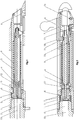
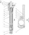
- the closure head 2 is fixed by the shoulder 10 in its axial movement relative to the chamber 3. It is a control piece 4 is provided, which is mounted axially displaceably in the closure head 2 and in the sleeve 3.
- the control piece 4 has in its front end region a radially outwardly extending control pin 12 whose surface is in contact with the cam 11 of the closure head 2 (see also FIGS. 6 a and 6 b).
- the chamber lever 6 can be seen, which is pivotally and positively mounted about a pivot pin 16 pivotally mounted at the rear end of the chamber 3 (see also FIGS. 11a, b and 12 ).
- This enables fast and tool-free dismantling.
- the control piece 4 is moved via an intermediate piece 17 connected thereto in the axial direction.
- the movement of the intermediate piece 17 can be done quite well by comparing the FIGS. 8a and 8b on the one hand and also the Figures 11a and 11b detect.
- the intermediate piece 17 is mounted axially displaceably in the chamber 3 and connected by the nose 18 with the control piece 4 (see Figures 2 and 4 ). At the rear end, the intermediate piece 17 is connected by the transverse groove 19 and the axle 20 with the chamber lever 6 (see FIG. 16 ).
- a locking pin 21 with a spring-loaded rocker 22 is disposed (see FIG. 2 ). This locking pin 21 snaps into a recess 23 (see FIG. 2 ), when one moves the chamber 3 from the sleeve 1 when repeating the weapon (see FIG. 4 ).
- the control piece 4 is pushed forward by the closing spring 9, which facilitates the closing operation and keeps the closing head 2 in the locked position (see FIG FIG. 2 ).
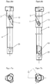
- control piece 4 is shown without the chamber 3, in which it is mounted axially displaceable. It can be seen here quite well the cam 11 in the closure head 2 and the control pin 12, which is guided in this control groove 11. Will now from the locked position according to FIG. 6 a the control piece 4 moves over the here not pictured intermediate piece 17 to the rear, then this leads to the rotational movement of the closure head in the in FIG. 6b shown position.
- the control piece 4 moves over the here not pictured intermediate piece 17 to the rear, then this leads to the rotational movement of the closure head in the in FIG. 6b shown position.
- the radial bore 25 of the control piece 4 in which the nose 18 (see FIG. 2 ) engages the intermediate piece, whereby the connection between the intermediate piece 17 and control piece 4 is made.
- the frontal views according to the FIGS. 7 a and 7 b can detect the size of the angle of rotation in the above-described process of locking the closure head 2 and it can be seen that it is a rotation angle of about 60 °, which is considerably more than in the known from the prior art devices. Furthermore, you can see in the FIGS. 7 a and 7 b, the outline shape of the closure head 2 in its end region, which is formed with lugs, projections or the like so that in the position according to FIGS. 7 a / 6 a the lock is given while after turning into position according to FIG. 7b the closure head 2 fits positively into a correspondingly shaped inner contour in the sleeve 1 and can therefore slide back in the sleeve. In this regard, reference is also made to the respective locking elements 7, 8 of the closure head 2 and sleeve 1, which in the illustration in accordance with FIGS. 3 and 4 to be released after unlocking.
- FIGS. 8 a and 8 b each show a side view in the rear of the weapon, wherein one recognizes the connection of spacer 17 and chamber lever 6, and the slot 24 in the chamber in which the intermediate piece 17 in the first phase of the movement of the chamber lever 6 to the rear , is guided until the release of the closure head 2.
- the closure with the chamber 3 moves out of the sleeve 1 axially to the rear and the intermediate piece 17 is then locked relative to the chamber 3.
- FIGS. 8 a and 8 b show the respective side views of FIGS. 8 a and 8 b, where in FIG. 9 looks at the weapon from above.
- the intermediate piece 17 on the upper side has a groove 26, via which it is guided displaceably on actuation of the chamber lever 6 for carrying out the pivoting movement relative to the rear part of the chamber. Because the intermediate piece 17 is thus guided in two mutually perpendicular regions (once on the sleeve 1 and once on the wider rear part of the chamber 3), it is trapped in its movement on the weapon.
- Said widened rear part of the chamber is designed so that it rests flush with the inserted into the sleeve 1 chamber 3 at the rear end of the sleeve 1 (see Figures 1 and 2 ).
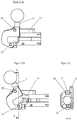
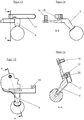
- FIG. 11 A and 11 b show again in the locked and in the unlocked position, the area with the chamber lever 6 and the intermediate piece 17, where you see the chamber lever 6 quasi from below.
- the axle 16 can be seen, around which the chamber lever 6 pivots and you can see the pin 20, which defines the pivot point of the articulated connection between the chamber lever 6 and the intermediate piece 17.
- FIG. 12 shows a section through the chamber lever 6, in which one recognizes the axle 16 and the groove 26 at the top of the intermediate piece 17th
- FIG. 13 shows the chamber lever 6 with the intermediate piece 17 and in the sectional view according to FIG. 14 you can see the chamber lever 6 with the axle 16 for the hinge axis. Furthermore, in FIG. 14 the nose 18 can be seen, via which the intermediate piece 17 is connected to the control piece 4.
- FIG. 15 shows in principle the side view of FIG. 13 , so that you can see the chamber lever 6 from below.
- the section line runs through the axle 16 and through the pin 20 so that it can be seen here how the chamber lever 6 is pivotally connected to the intermediate piece 17 via the pin 20.
Landscapes
- Engineering & Computer Science (AREA)
- General Engineering & Computer Science (AREA)
- Lock And Its Accessories (AREA)
Priority Applications (1)
| Application Number | Priority Date | Filing Date | Title |
|---|---|---|---|
| EP17161425.8A EP3376151B1 (fr) | 2017-03-16 | 2017-03-16 | Culasse pour une arme à feu |
Applications Claiming Priority (1)
| Application Number | Priority Date | Filing Date | Title |
|---|---|---|---|
| EP17161425.8A EP3376151B1 (fr) | 2017-03-16 | 2017-03-16 | Culasse pour une arme à feu |
Publications (2)
| Publication Number | Publication Date |
|---|---|
| EP3376151A1 true EP3376151A1 (fr) | 2018-09-19 |
| EP3376151B1 EP3376151B1 (fr) | 2020-02-12 |
Family
ID=58358432
Family Applications (1)
| Application Number | Title | Priority Date | Filing Date |
|---|---|---|---|
| EP17161425.8A Active EP3376151B1 (fr) | 2017-03-16 | 2017-03-16 | Culasse pour une arme à feu |
Country Status (1)
| Country | Link |
|---|---|
| EP (1) | EP3376151B1 (fr) |
Citations (6)
| Publication number | Priority date | Publication date | Assignee | Title |
|---|---|---|---|---|
| DE49192C (de) * | EISENWERKE GAGGE-NAU, Actien - Gesellschaft in Gaggenau, Baden | GeradezugVerschlufs mit wagrecht schwingendem Handgriff | ||
| DE3432537A1 (de) * | 1984-09-05 | 1986-03-13 | Peter 8201 Rohrdorf Fortner jun. | Repetiergewehr, insbesondere als sportgewehr wie fuer biathlon |
| DE4305700C1 (de) | 1993-02-25 | 1994-10-27 | Blaser Horst Jagdwaffen | Verschluß für eine Schußwaffe, insbesondere ein Repetiergewehr |
| DE19608872C1 (de) | 1996-03-07 | 1997-06-05 | Peter Fortner | Verschlußeinrichtung für Schußwaffen, insbesondere für Repetiergewehre |
| EP0784194A2 (fr) | 1996-01-09 | 1997-07-16 | Mauser-Werke Oberndorf Waffensysteme GmbH | Culasse pour arme à feu |
| DE102012217686A1 (de) * | 2012-09-28 | 2014-04-03 | Andreas Volckmann | Geradezug-Repetiergewehr mit einem Verschlussmechanismus |
-
2017
- 2017-03-16 EP EP17161425.8A patent/EP3376151B1/fr active Active
Patent Citations (6)
| Publication number | Priority date | Publication date | Assignee | Title |
|---|---|---|---|---|
| DE49192C (de) * | EISENWERKE GAGGE-NAU, Actien - Gesellschaft in Gaggenau, Baden | GeradezugVerschlufs mit wagrecht schwingendem Handgriff | ||
| DE3432537A1 (de) * | 1984-09-05 | 1986-03-13 | Peter 8201 Rohrdorf Fortner jun. | Repetiergewehr, insbesondere als sportgewehr wie fuer biathlon |
| DE4305700C1 (de) | 1993-02-25 | 1994-10-27 | Blaser Horst Jagdwaffen | Verschluß für eine Schußwaffe, insbesondere ein Repetiergewehr |
| EP0784194A2 (fr) | 1996-01-09 | 1997-07-16 | Mauser-Werke Oberndorf Waffensysteme GmbH | Culasse pour arme à feu |
| DE19608872C1 (de) | 1996-03-07 | 1997-06-05 | Peter Fortner | Verschlußeinrichtung für Schußwaffen, insbesondere für Repetiergewehre |
| DE102012217686A1 (de) * | 2012-09-28 | 2014-04-03 | Andreas Volckmann | Geradezug-Repetiergewehr mit einem Verschlussmechanismus |
Also Published As
| Publication number | Publication date |
|---|---|
| EP3376151B1 (fr) | 2020-02-12 |
Similar Documents
| Publication | Publication Date | Title |
|---|---|---|
| DE102016120891A1 (de) | Verschluss für Schusswaffen | |
| AT392818B (de) | Schliesssystem | |
| DE29820711U1 (de) | Drehriegelverschluß mit Zugeinrichtung | |
| DE2711124B1 (de) | Handpipette | |
| WO2016197162A1 (fr) | Dispositif d'éjection d'une partie de meuble mobile | |
| EP1688566B1 (fr) | Serrure avec levier de déclenchement pivotant | |
| DE3609043C2 (de) | Elektrische Sicherheitsschaltvorrichtung | |
| DE69207320T2 (de) | Verbesserter Schloss mit einer Einrichtung zwecks Öffnen im Notfall | |
| DE2910295C2 (de) | Abschließbarer Drehgriff für Fenster und Türen | |
| DE19939734B4 (de) | Aus Schließzylinder und Schlüssel bestehende Schließvorrichtung | |
| EP0597170B1 (fr) | Serrure à verrou tournant | |
| EP3426867B1 (fr) | Serrure | |
| DE2347405C3 (de) | Zylinderförmiges Einsteckschloß | |
| EP3034728A1 (fr) | Dispositif limiteur d'ouverture | |
| EP3376151B1 (fr) | Culasse pour une arme à feu | |
| DE3630747C2 (de) | Türschloß, insbesondere Einsteckschloß | |
| DE3427713A1 (de) | Mehrtourig schliessendes treibstangenschloss | |
| DE69807608T2 (de) | Schliessvorrichtung, insbesondere Einsteckschloss mit einer Falle, für eine Fenstertür oder dergleichen | |
| DE69204044T2 (de) | Sicherheitsschloss für eine Haustüre oder dgl. | |
| DE69807801T2 (de) | Verriegelungsvorrichtung, insbesondere Einsteckschloss für den Flügel einer Tür oder eines Fensters | |
| DE19604594C1 (de) | Kombination eines Schließzylinders und eines Flachschlüssels für Waren- und Spielautomaten, Geldwechselautomaten, Fahrkartenautomaten und dergleichen, mit Stiftzuhaltungen | |
| DE2743091C2 (de) | Vorrichtung zum Vergrößern des Ausschließhubes eines eintourig mittels Schlüssel schließbaren Schubriegels in einem Schloß mit Falle und Schubriegel | |
| DE3427712A1 (de) | Treibstangenschloss | |
| EP0806534B1 (fr) | Crémone | |
| DE4014042A1 (de) | Treibstangenschloss |
Legal Events
| Date | Code | Title | Description |
|---|---|---|---|
| PUAI | Public reference made under article 153(3) epc to a published international application that has entered the european phase |
Free format text: ORIGINAL CODE: 0009012 |
|
| STAA | Information on the status of an ep patent application or granted ep patent |
Free format text: STATUS: REQUEST FOR EXAMINATION WAS MADE |
|
| 17P | Request for examination filed |
Effective date: 20171006 |
|
| AK | Designated contracting states |
Kind code of ref document: A1 Designated state(s): AL AT BE BG CH CY CZ DE DK EE ES FI FR GB GR HR HU IE IS IT LI LT LU LV MC MK MT NL NO PL PT RO RS SE SI SK SM TR |
|
| AX | Request for extension of the european patent |
Extension state: BA ME |
|
| RIC1 | Information provided on ipc code assigned before grant |
Ipc: F41A 3/20 20060101AFI20190902BHEP |
|
| GRAP | Despatch of communication of intention to grant a patent |
Free format text: ORIGINAL CODE: EPIDOSNIGR1 |
|
| STAA | Information on the status of an ep patent application or granted ep patent |
Free format text: STATUS: GRANT OF PATENT IS INTENDED |
|
| INTG | Intention to grant announced |
Effective date: 20191115 |
|
| GRAS | Grant fee paid |
Free format text: ORIGINAL CODE: EPIDOSNIGR3 |
|
| GRAA | (expected) grant |
Free format text: ORIGINAL CODE: 0009210 |
|
| STAA | Information on the status of an ep patent application or granted ep patent |
Free format text: STATUS: THE PATENT HAS BEEN GRANTED |
|
| AK | Designated contracting states |
Kind code of ref document: B1 Designated state(s): AL AT BE BG CH CY CZ DE DK EE ES FI FR GB GR HR HU IE IS IT LI LT LU LV MC MK MT NL NO PL PT RO RS SE SI SK SM TR |
|
| REG | Reference to a national code |
Ref country code: GB Ref legal event code: FG4D Free format text: NOT ENGLISH |
|
| REG | Reference to a national code |
Ref country code: CH Ref legal event code: EP |
|
| REG | Reference to a national code |
Ref country code: AT Ref legal event code: REF Ref document number: 1232689 Country of ref document: AT Kind code of ref document: T Effective date: 20200215 |
|
| REG | Reference to a national code |
Ref country code: IE Ref legal event code: FG4D Free format text: LANGUAGE OF EP DOCUMENT: GERMAN |
|
| REG | Reference to a national code |
Ref country code: DE Ref legal event code: R096 Ref document number: 502017003721 Country of ref document: DE |
|
| REG | Reference to a national code |
Ref country code: CH Ref legal event code: NV Representative=s name: DENNEMEYER AG, CH |
|
| REG | Reference to a national code |
Ref country code: FI Ref legal event code: FGE |
|
| REG | Reference to a national code |
Ref country code: SE Ref legal event code: TRGR |
|
| PG25 | Lapsed in a contracting state [announced via postgrant information from national office to epo] |
Ref country code: RS Free format text: LAPSE BECAUSE OF FAILURE TO SUBMIT A TRANSLATION OF THE DESCRIPTION OR TO PAY THE FEE WITHIN THE PRESCRIBED TIME-LIMIT Effective date: 20200212 Ref country code: NO Free format text: LAPSE BECAUSE OF FAILURE TO SUBMIT A TRANSLATION OF THE DESCRIPTION OR TO PAY THE FEE WITHIN THE PRESCRIBED TIME-LIMIT Effective date: 20200512 |
|
| REG | Reference to a national code |
Ref country code: LT Ref legal event code: MG4D |
|
| REG | Reference to a national code |
Ref country code: NL Ref legal event code: MP Effective date: 20200212 |
|
| PG25 | Lapsed in a contracting state [announced via postgrant information from national office to epo] |
Ref country code: LV Free format text: LAPSE BECAUSE OF FAILURE TO SUBMIT A TRANSLATION OF THE DESCRIPTION OR TO PAY THE FEE WITHIN THE PRESCRIBED TIME-LIMIT Effective date: 20200212 Ref country code: BG Free format text: LAPSE BECAUSE OF FAILURE TO SUBMIT A TRANSLATION OF THE DESCRIPTION OR TO PAY THE FEE WITHIN THE PRESCRIBED TIME-LIMIT Effective date: 20200512 Ref country code: IS Free format text: LAPSE BECAUSE OF FAILURE TO SUBMIT A TRANSLATION OF THE DESCRIPTION OR TO PAY THE FEE WITHIN THE PRESCRIBED TIME-LIMIT Effective date: 20200612 Ref country code: GR Free format text: LAPSE BECAUSE OF FAILURE TO SUBMIT A TRANSLATION OF THE DESCRIPTION OR TO PAY THE FEE WITHIN THE PRESCRIBED TIME-LIMIT Effective date: 20200513 Ref country code: HR Free format text: LAPSE BECAUSE OF FAILURE TO SUBMIT A TRANSLATION OF THE DESCRIPTION OR TO PAY THE FEE WITHIN THE PRESCRIBED TIME-LIMIT Effective date: 20200212 |
|
| PG25 | Lapsed in a contracting state [announced via postgrant information from national office to epo] |
Ref country code: NL Free format text: LAPSE BECAUSE OF FAILURE TO SUBMIT A TRANSLATION OF THE DESCRIPTION OR TO PAY THE FEE WITHIN THE PRESCRIBED TIME-LIMIT Effective date: 20200212 |
|
| PG25 | Lapsed in a contracting state [announced via postgrant information from national office to epo] |
Ref country code: SK Free format text: LAPSE BECAUSE OF FAILURE TO SUBMIT A TRANSLATION OF THE DESCRIPTION OR TO PAY THE FEE WITHIN THE PRESCRIBED TIME-LIMIT Effective date: 20200212 Ref country code: SM Free format text: LAPSE BECAUSE OF FAILURE TO SUBMIT A TRANSLATION OF THE DESCRIPTION OR TO PAY THE FEE WITHIN THE PRESCRIBED TIME-LIMIT Effective date: 20200212 Ref country code: EE Free format text: LAPSE BECAUSE OF FAILURE TO SUBMIT A TRANSLATION OF THE DESCRIPTION OR TO PAY THE FEE WITHIN THE PRESCRIBED TIME-LIMIT Effective date: 20200212 Ref country code: DK Free format text: LAPSE BECAUSE OF FAILURE TO SUBMIT A TRANSLATION OF THE DESCRIPTION OR TO PAY THE FEE WITHIN THE PRESCRIBED TIME-LIMIT Effective date: 20200212 Ref country code: ES Free format text: LAPSE BECAUSE OF FAILURE TO SUBMIT A TRANSLATION OF THE DESCRIPTION OR TO PAY THE FEE WITHIN THE PRESCRIBED TIME-LIMIT Effective date: 20200212 Ref country code: LT Free format text: LAPSE BECAUSE OF FAILURE TO SUBMIT A TRANSLATION OF THE DESCRIPTION OR TO PAY THE FEE WITHIN THE PRESCRIBED TIME-LIMIT Effective date: 20200212 Ref country code: PT Free format text: LAPSE BECAUSE OF FAILURE TO SUBMIT A TRANSLATION OF THE DESCRIPTION OR TO PAY THE FEE WITHIN THE PRESCRIBED TIME-LIMIT Effective date: 20200705 Ref country code: RO Free format text: LAPSE BECAUSE OF FAILURE TO SUBMIT A TRANSLATION OF THE DESCRIPTION OR TO PAY THE FEE WITHIN THE PRESCRIBED TIME-LIMIT Effective date: 20200212 |
|
| REG | Reference to a national code |
Ref country code: DE Ref legal event code: R097 Ref document number: 502017003721 Country of ref document: DE |
|
| PG25 | Lapsed in a contracting state [announced via postgrant information from national office to epo] |
Ref country code: MC Free format text: LAPSE BECAUSE OF FAILURE TO SUBMIT A TRANSLATION OF THE DESCRIPTION OR TO PAY THE FEE WITHIN THE PRESCRIBED TIME-LIMIT Effective date: 20200212 |
|
| REG | Reference to a national code |
Ref country code: DE Ref legal event code: R082 Ref document number: 502017003721 Country of ref document: DE Representative=s name: FRITZ & BRANDENBURG PATENTANWAELTE, DE |
|
| PLBE | No opposition filed within time limit |
Free format text: ORIGINAL CODE: 0009261 |
|
| STAA | Information on the status of an ep patent application or granted ep patent |
Free format text: STATUS: NO OPPOSITION FILED WITHIN TIME LIMIT |
|
| PG25 | Lapsed in a contracting state [announced via postgrant information from national office to epo] |
Ref country code: LU Free format text: LAPSE BECAUSE OF NON-PAYMENT OF DUE FEES Effective date: 20200316 |
|
| 26N | No opposition filed |
Effective date: 20201113 |
|
| PG25 | Lapsed in a contracting state [announced via postgrant information from national office to epo] |
Ref country code: IE Free format text: LAPSE BECAUSE OF NON-PAYMENT OF DUE FEES Effective date: 20200316 |
|
| PG25 | Lapsed in a contracting state [announced via postgrant information from national office to epo] |
Ref country code: SI Free format text: LAPSE BECAUSE OF FAILURE TO SUBMIT A TRANSLATION OF THE DESCRIPTION OR TO PAY THE FEE WITHIN THE PRESCRIBED TIME-LIMIT Effective date: 20200212 Ref country code: PL Free format text: LAPSE BECAUSE OF FAILURE TO SUBMIT A TRANSLATION OF THE DESCRIPTION OR TO PAY THE FEE WITHIN THE PRESCRIBED TIME-LIMIT Effective date: 20200212 |
|
| GBPC | Gb: european patent ceased through non-payment of renewal fee |
Effective date: 20210316 |
|
| PG25 | Lapsed in a contracting state [announced via postgrant information from national office to epo] |
Ref country code: GB Free format text: LAPSE BECAUSE OF NON-PAYMENT OF DUE FEES Effective date: 20210316 |
|
| REG | Reference to a national code |
Ref country code: DE Ref legal event code: R082 Ref document number: 502017003721 Country of ref document: DE Representative=s name: DUDA, RAFAEL THOMAS, DIPL.-ING. DR. RER. NAT., DE |
|
| PG25 | Lapsed in a contracting state [announced via postgrant information from national office to epo] |
Ref country code: TR Free format text: LAPSE BECAUSE OF FAILURE TO SUBMIT A TRANSLATION OF THE DESCRIPTION OR TO PAY THE FEE WITHIN THE PRESCRIBED TIME-LIMIT Effective date: 20200212 Ref country code: MT Free format text: LAPSE BECAUSE OF FAILURE TO SUBMIT A TRANSLATION OF THE DESCRIPTION OR TO PAY THE FEE WITHIN THE PRESCRIBED TIME-LIMIT Effective date: 20200212 Ref country code: CY Free format text: LAPSE BECAUSE OF FAILURE TO SUBMIT A TRANSLATION OF THE DESCRIPTION OR TO PAY THE FEE WITHIN THE PRESCRIBED TIME-LIMIT Effective date: 20200212 |
|
| PG25 | Lapsed in a contracting state [announced via postgrant information from national office to epo] |
Ref country code: MK Free format text: LAPSE BECAUSE OF FAILURE TO SUBMIT A TRANSLATION OF THE DESCRIPTION OR TO PAY THE FEE WITHIN THE PRESCRIBED TIME-LIMIT Effective date: 20200212 Ref country code: AL Free format text: LAPSE BECAUSE OF FAILURE TO SUBMIT A TRANSLATION OF THE DESCRIPTION OR TO PAY THE FEE WITHIN THE PRESCRIBED TIME-LIMIT Effective date: 20200212 |
|
| P01 | Opt-out of the competence of the unified patent court (upc) registered |
Effective date: 20230914 |
|
| PGFP | Annual fee paid to national office [announced via postgrant information from national office to epo] |
Ref country code: AT Payment date: 20240321 Year of fee payment: 8 |
|
| PGFP | Annual fee paid to national office [announced via postgrant information from national office to epo] |
Ref country code: FI Payment date: 20240320 Year of fee payment: 8 Ref country code: CZ Payment date: 20240307 Year of fee payment: 8 |
|
| PGFP | Annual fee paid to national office [announced via postgrant information from national office to epo] |
Ref country code: SE Payment date: 20240320 Year of fee payment: 8 Ref country code: IT Payment date: 20240322 Year of fee payment: 8 Ref country code: FR Payment date: 20240328 Year of fee payment: 8 Ref country code: BE Payment date: 20240320 Year of fee payment: 8 |
|
| PGFP | Annual fee paid to national office [announced via postgrant information from national office to epo] |
Ref country code: CH Payment date: 20240401 Year of fee payment: 8 |
|
| PG25 | Lapsed in a contracting state [announced via postgrant information from national office to epo] |
Ref country code: FI Free format text: LAPSE BECAUSE OF NON-PAYMENT OF DUE FEES Effective date: 20250316 |
|
| PG25 | Lapsed in a contracting state [announced via postgrant information from national office to epo] |
Ref country code: CZ Free format text: LAPSE BECAUSE OF NON-PAYMENT OF DUE FEES Effective date: 20250316 |
|
| REG | Reference to a national code |
Ref country code: CH Ref legal event code: H13 Free format text: ST27 STATUS EVENT CODE: U-0-0-H10-H13 (AS PROVIDED BY THE NATIONAL OFFICE) Effective date: 20251023 |
|
| REG | Reference to a national code |
Ref country code: SE Ref legal event code: EUG |
|
| REG | Reference to a national code |
Ref country code: AT Ref legal event code: MM01 Ref document number: 1232689 Country of ref document: AT Kind code of ref document: T Effective date: 20250316 |
|
| REG | Reference to a national code |
Ref country code: BE Ref legal event code: MM Effective date: 20250331 |
|
| PG25 | Lapsed in a contracting state [announced via postgrant information from national office to epo] |
Ref country code: AT Free format text: LAPSE BECAUSE OF NON-PAYMENT OF DUE FEES Effective date: 20250316 |
|
| PG25 | Lapsed in a contracting state [announced via postgrant information from national office to epo] |
Ref country code: FR Free format text: LAPSE BECAUSE OF NON-PAYMENT OF DUE FEES Effective date: 20250331 Ref country code: IT Free format text: LAPSE BECAUSE OF NON-PAYMENT OF DUE FEES Effective date: 20250316 |
|
| PG25 | Lapsed in a contracting state [announced via postgrant information from national office to epo] |
Ref country code: BE Free format text: LAPSE BECAUSE OF NON-PAYMENT OF DUE FEES Effective date: 20250331 |
|
| PG25 | Lapsed in a contracting state [announced via postgrant information from national office to epo] |
Ref country code: CH Free format text: LAPSE BECAUSE OF NON-PAYMENT OF DUE FEES Effective date: 20250331 |
|
| PG25 | Lapsed in a contracting state [announced via postgrant information from national office to epo] |
Ref country code: SE Free format text: LAPSE BECAUSE OF NON-PAYMENT OF DUE FEES Effective date: 20250317 |
|
| PGFP | Annual fee paid to national office [announced via postgrant information from national office to epo] |
Ref country code: DE Payment date: 20260320 Year of fee payment: 10 |